EP0229206A1 - Container closure with a tamper-indicating band - Google Patents
Container closure with a tamper-indicating band Download PDFInfo
- Publication number
- EP0229206A1 EP0229206A1 EP86100328A EP86100328A EP0229206A1 EP 0229206 A1 EP0229206 A1 EP 0229206A1 EP 86100328 A EP86100328 A EP 86100328A EP 86100328 A EP86100328 A EP 86100328A EP 0229206 A1 EP0229206 A1 EP 0229206A1
- Authority
- EP
- European Patent Office
- Prior art keywords
- closure
- wedge
- container
- guarantee ring
- bead
- Prior art date
- Legal status (The legal status is an assumption and is not a legal conclusion. Google has not performed a legal analysis and makes no representation as to the accuracy of the status listed.)
- Withdrawn
Links
Images

Classifications
-
- B—PERFORMING OPERATIONS; TRANSPORTING
- B65—CONVEYING; PACKING; STORING; HANDLING THIN OR FILAMENTARY MATERIAL
- B65D—CONTAINERS FOR STORAGE OR TRANSPORT OF ARTICLES OR MATERIALS, e.g. BAGS, BARRELS, BOTTLES, BOXES, CANS, CARTONS, CRATES, DRUMS, JARS, TANKS, HOPPERS, FORWARDING CONTAINERS; ACCESSORIES, CLOSURES, OR FITTINGS THEREFOR; PACKAGING ELEMENTS; PACKAGES
- B65D41/00—Caps, e.g. crown caps or crown seals, i.e. members having parts arranged for engagement with the external periphery of a neck or wall defining a pouring opening or discharge aperture; Protective cap-like covers for closure members, e.g. decorative covers of metal foil or paper
- B65D41/32—Caps or cap-like covers with lines of weakness, tearing-strips, tags, or like opening or removal devices, e.g. to facilitate formation of pouring openings
- B65D41/34—Threaded or like caps or cap-like covers provided with tamper elements formed in, or attached to, the closure skirt
- B65D41/3423—Threaded or like caps or cap-like covers provided with tamper elements formed in, or attached to, the closure skirt with flexible tabs, or elements rotated from a non-engaging to an engaging position, formed on the tamper element or in the closure skirt
- B65D41/3428—Threaded or like caps or cap-like covers provided with tamper elements formed in, or attached to, the closure skirt with flexible tabs, or elements rotated from a non-engaging to an engaging position, formed on the tamper element or in the closure skirt the tamper element being integrally connected to the closure by means of bridges
Definitions
- the invention relates to a closure with a guarantee attached to it for containers which have a muzzle near their mouth, the guarantee ring being connected to the cap of the closure via webs which serve as predetermined tear points.
- Closures with guarantee rings are increasingly being used to prevent the contents of the container from being partially emptied by unauthorized persons, but later the container is sold as full, because no one has noticed this removal or because the removal can only be determined after close inspection could.
- closures with guarantee rings those should be considered in which the guarantee ring is connected to the cap of the closure via thin webs on the front side of the part encompassing the container. The guarantee therefore has practically the same diameter as this part.
- This arrangement is particularly suitable for containers with a so-called mouth bead, because then when the guarantee ring is attached, the guarantee ring is located at the lower edge of this mouth bead, i.e. at a point where this bead of large diameter in the neck of the container smaller diameter passes. The guarantee ring then engages behind the bead so that it is torn off when the lock is lifted.
- the type of this gripping can practically only be solved properly by making the guarantee ring from heat-shrinkable plastic.
- the closure is put on and the containers then move through a so-called heat shrink tunnel.
- the guarantee ring is warmed up by targeted thermal radiation.
- Its inner diameter, which initially corresponds to that of the bead in order to bring the guarantee ring over the bead at all, is now decreasing; in most cases the guarantee ring lies against the transition point between the bead and the neck of the container or is at most only a very minimal distance.
- the closure can therefore only be opened for the first time by visible destruction or at least by visible tearing off of the guarantee ring.
- the invention therefore aims to get rid of heat shrinkage and to create a closure with a guarantee ring which also detects the mouth of the container on the underside, as was previously only possible with heat-shrunk material.
- a closure with a guarantee ring of the type mentioned at the outset which is characterized by at least one wedge attached to the inside of the guarantee ring and projecting inwards, which forms an angle of less than 90 ° with the inner wall, against the Closure cap is inclined, made of the same material as this and the guarantee ring and is at its free end a radial distance from the axis of rotation of the closure, which is determined such that it is smaller than the largest radius of the muzzle when the closure is placed on the container of the container.
- the container in general, preferably a beverage bottle, with 2 its mouth, which has a mouth bead 3.
- its diameter is larger than the container neck 4, so that a transition zone 5 is formed which acts like a constriction.
- the closure which is preferably made of plastic, has a closure cap 6, which comprises a cap cover 7, in a known manner.
- a closure cap 6 which comprises a cap cover 7, in a known manner.
- the bottom section of said part 8, the webs 9 and the inner wall 11 of the guarantee ring 10 the same diameter or the same radial distance from the axis of rotation 12 of the closure.
- At least one wedge 13 is arranged on the inner wall 11 of the guarantee ring 10. This stands almost, but only almost, at right angles to it; it must have an angle that is less than 90 °, whereby it or its longitudinal center plane 14 is inclined towards the closure cap 6. We will return to this essential detail. An angle of 60 ° has proven to be expedient.
- the wedge 13 extends along the inner wall 10 in the circumferential direction thereof, its length L being different as required. It can be relatively small, but on the other hand it can also be as large as is technically possible in the injection mold used to produce the closure. In experiments, a length up to 40% of the diameter of the inner wall 10 has proven to be advantageous if only one wedge is present; if more than one, this percentage may be lower.
- the radius r of the free end 15 of the wedge 13 to the axis 12 is smaller than the largest radius R of the mouth bead 3. Since the containers are standardized and thus also the radii of their mouth beads, this radius r can be below Consideration of the tolerances is predefined fairly precisely and thus also standardized.
- the free end 15 thus comes to rest under the muzzle bead 3 if the wedge is also mounted at the correct height, ie at the correct distance a from the underside of the cap lid 7. When putting on the lock, the wedge must squeeze past the entire muzzle bead 3 from top to bottom.
- This static friction can be increased if, according to the embodiment according to FIG. 3, the closure lies even closer to the container mouth, that is to say if the webs 9 rest against the mouth bead 3.
- the radius of these webs and that of the inner wall 11 thus correspond to the largest radius R of the mouth bead 3, and thus the wedge 13 also has the same radius R where it originates from the inner wall.
- the wedge 13 then projects further under the mouth bead 3, so that when the closure is removed, the entire static friction, caused by the webs 9 and the wedge 13 abutting the muzzle, tears these webs.
Abstract
Description
Die Erfindung betrifft einen Verschluss mit an ihm angebrachtem Garantierung für Behälter, die nahe ihrer Mündung einen Mündungswulst aufweisen, wobei der Garantiering über Stege, die als Sollreissstellen dienen, mit der Kappe des Verschlusses verbunden ist.The invention relates to a closure with a guarantee attached to it for containers which have a muzzle near their mouth, the guarantee ring being connected to the cap of the closure via webs which serve as predetermined tear points.
Verschlüsse mit Garantieringen kommen in zunehmendem Masse in Gebrauch, um zu verhindern, dass der Inhalt des Behälters von Unbefugten teilweise geleert, der Behälter dann später aber als voll verkauft wird, weil niemand diese Entnahme bemerkt hat oder weil man die Entnahme erst nach genauer Kontrolle feststellen konnte. Unter den zahlreichen Varianten von Verschlüssen mit Garantieringen sollen diejenigen in Betracht gezogen werden, bei welchen der Garantiering mit der Kappe des Verschlusses über dünne Stege an der Stirnseite des den Behälter umgreifenden Teils verbunden ist. Der Garantierung weist also praktisch denselben Durchmesser wie dieser Teil auf. Diese Anordnung eignet sich vor allem für Behälter mit einem sogenannten Mündungswulst, weil dann bei aufgesetztem Verschluss der Garantiering sich am unteren Rand dieses Mündungswulstes befindet, also an einer Stelle, an welcher dieser Wulst von grossem Durchmesser in den Hals des Behälters von kleinerem Durchmesser übergeht. Dort hintergreift dann der Garantiering den Wulst, sodass er beim Heben des Verschlusses abgerissen wird.Closures with guarantee rings are increasingly being used to prevent the contents of the container from being partially emptied by unauthorized persons, but later the container is sold as full, because no one has noticed this removal or because the removal can only be determined after close inspection could. Among the numerous variants of closures with guarantee rings, those should be considered in which the guarantee ring is connected to the cap of the closure via thin webs on the front side of the part encompassing the container. The guarantee therefore has practically the same diameter as this part. This arrangement is particularly suitable for containers with a so-called mouth bead, because then when the guarantee ring is attached, the guarantee ring is located at the lower edge of this mouth bead, i.e. at a point where this bead of large diameter in the neck of the container smaller diameter passes. The guarantee ring then engages behind the bead so that it is torn off when the lock is lifted.
Die Art dieses Hintergreifens lässt sich praktisch nur dadurch einwandfrei lösen, dass man den Garantiering aus wärmeschrumpfbarem Kunststoff macht. Der Verschluss wird aufgesetzt, und die Behälter wandern dann durch einen sogenannten Wärmeschrumpftunnel. In diesem wird durch gezielt eingesetzte Wärmestrahlung der Garantiering erwärmt. Sein Innendurchmesser, der anfänglich demjenigen des Wulstes entspricht, um den Garantiering überhaupt über den Wulst hinwegzubringen, nimmt nun ab; der Garantiering legt sich in den meisten Fällen gegen die Uebergangsstelle zwischen Wulst und Hals des Behälters an oder weist höchstens noch einen sehr minimen Abstand auf. Der Verschluss kann also nur noch durch sichtbare Zerstörung oder wenigstens durch sichtbares Abreissen des Garantieringes erstmalig geöffnet werden.The type of this gripping can practically only be solved properly by making the guarantee ring from heat-shrinkable plastic. The closure is put on and the containers then move through a so-called heat shrink tunnel. In this, the guarantee ring is warmed up by targeted thermal radiation. Its inner diameter, which initially corresponds to that of the bead in order to bring the guarantee ring over the bead at all, is now decreasing; in most cases the guarantee ring lies against the transition point between the bead and the neck of the container or is at most only a very minimal distance. The closure can therefore only be opened for the first time by visible destruction or at least by visible tearing off of the guarantee ring.
Obschon man heute diese Wärmeschrumpfung in Tunnels beherrscht, ist sie doch aufwendig. Der Tunnel muss sehr leistungsfähig sein, weil die Behälter wegen des grossen Ausstosses der Abfüllmaschine nur kurze Zeit in ihm verweilen können. Der Energieverbrauch ist also sehr hoch.Although this heat shrinkage is controlled in tunnels today, it is complex. The tunnel has to be very efficient because the containers can only stay in it for a short time due to the high output of the filling machine. So the energy consumption is very high.
Die Erfindung bezweckt daher, vom Wärmeschrumpfen loszukommen und einen Verschluss mit Garantiering zu schaffen, welcher den Mündungswulst des Behälters ebenso an der Unterseite erfasst wie dies bisher nur mit wärmegeschrumpften Material möglich war.The invention therefore aims to get rid of heat shrinkage and to create a closure with a guarantee ring which also detects the mouth of the container on the underside, as was previously only possible with heat-shrunk material.
Dies wird erfindungsgemäss durch einen Verschluss mit Garantiering der eingangs erwähnten Art erreicht, welcher gekennzeichnet ist durch mindestens einen an der Innenseite des Garantieringes angebrachten und nach innen vorstehenden Keil, der mit der Innenwand einen Winkel von weniger als 90° bildet, wobei er gegen die Verschlusskappe hin geneigt ist, aus demselben Material wie diese und der Garantiering besteht und an seinem freien Ende einen radialen Abstand von der Rotationsachse des Verschlusses aufweist, der derart bestimmt ist, dass er bei auf dem Behälter aufgesetztem Verschluss kleiner ist als der grösste Radius des Mündungswulstes des Behälters.This is achieved according to the invention by a closure with a guarantee ring of the type mentioned at the outset, which is characterized by at least one wedge attached to the inside of the guarantee ring and projecting inwards, which forms an angle of less than 90 ° with the inner wall, against the Closure cap is inclined, made of the same material as this and the guarantee ring and is at its free end a radial distance from the axis of rotation of the closure, which is determined such that it is smaller than the largest radius of the muzzle when the closure is placed on the container of the container.
Ausführungsbeispiele des erfindungsgemässen Verschlusses sind in den beiliegenden Figuren dargestellt, es zeigen:
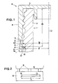
- Fig. 1 einen Schnitt durch die eine Hälfte des Verschlusses sowie des Behälters, auf dem der Verschluss aufsitzt, in einer ersten Ausführungsform,
- Fig. 2 eine Ansicht eines Keils, in radialer Richtung des Verschlusses gesehen, und
- Fig. 3 einen Schnitt wie Fig. 1 einer zweiten Ausführungsform.
- 1 shows a section through one half of the closure and of the container on which the closure is seated, in a first embodiment,
- Fig. 2 is a view of a wedge, seen in the radial direction of the closure, and
- Fig. 3 shows a section like Fig. 1 of a second embodiment.
Mit 1 ist der Behälter im allgemeinen, vorzugsweise eine Getränkeflasche, mit 2 seine Mündung bezeichnet, die einen Mündungswulst 3 aufweist. Wie ersichtlich, ist dessen Durchmesser grösser als der Behälterhals 4, sodass eine Uebergangszone 5 gebildet wird, die wie eine Einschnürung wirkt.1 with the container in general, preferably a beverage bottle, with 2 its mouth, which has a
Der vorzugsweise aus Kunststoff bestehende Verschluss weist nach bekannter Art eine Verschlusskappe 6 auf, die einen Kappendeckel 7 umfasst. An der unteren oder Stirnseite des den Behälter 1 umgreifenden Teils 8 der Verschlusskappe 6 sind am Umfang verteilt mehrere dünne Stege 9 angebracht, die zusammen einen Garantiering 10 tragen. Wie ersichtlich, weisen der unterste Abschnitt des genannten Teils 8, die Stege 9 und die Innenwand 11 des Garantie ringes 10 denselben Durchmesser bzw. denselben radialen Abstand von der Rotationsachse 12 des Verschlusses auf.The closure, which is preferably made of plastic, has a
Neu ist nun, dass an der Innenwand 11 des Garantieringes 10 wenigstens ein Keil 13 angeordnet ist. Dieser steht beinahe, aber nur beinahe, rechtwinklig zu ihr; er muss einen Winkel aufweisen, der kleiner als 90° ist, wobei er bzw. seine Längsmittelebene 14 gegen die Verschlusskappe 6 hin geneigt ist. Auf diese wesentliche Einzelheit wird noch zurückgekommen. Als zweckmässig hat sich ein Winkel von 60° erwiesen. Im übrigen erstreckt sich der Keil 13 entlang der Innenwand 10 in Umfangsrichtung derselben, wobei seine Länge L je nach Bedarf verschieden ist. Sie kann relativ gering, andererseits aber auch derart gross sein, wie dies bei der zur Herstellung des Verschlusses verwendeten Spritzgussform technisch möglich ist. Als vorteilhaft hat sich in Versuchen eine Länge bis 40 % des Durchmessers der Innenwand 10 erwiesen, wenn nur ein Keil vorhanden ist; bei mehr als einem kann dieser Prozentsatz geringer sein.What is new is that at least one
Aus der Zeichnung ist auch ersichtlich, dass der Radius r des freien Endes 15 des Keils 13 zur Achse 12 kleiner ist als der grösste Radius R des Mündungswulstes 3. Da die Behälter normiert sind und damit auch die Radien ihrer Mündungswulste, kann dieser Radius r unter Berücksichtigung der Toleranzen ziemlich genau vorbestimmt und somit ebenfalls normiert werden. Das freie Ende 15 kommt also unter den Mündungswulst 3 zu liegen, wenn ausserdem auch der Keil auf der richtigen Höhe, d.h. im richtigen Abstand a von der Unterseite des Kappendeckels 7 angebracht ist. Beim Aufsetzen des Verschlusses muss sich der Keil am ganzen Mündungswulst 3 von oben bis unten vorbeizwängen. Dies kann, wenn nur ein Keil vorhanden ist, dadurch erfolgen, dass der ganze Garantiering 10 unter Ausnützung seines Spiels sowie der Elastizität der Stege relativ zum Behälter etwas seitlich verschoben wird, bis der Keil unter den Wulst gelangt. Bei mehreren Keilen findet eine elasti sche Aufweitung des Garantieringes statt, die übrigens auch bei nur einem Keil örtlich im Bereich desselben auftreten kann, wenn die Toleranzen zwischen Verschluss und Behälter etwas knapp sind. Befindet sich der Keil 13 einmal unter dem Wulst 3, legt er sich beim Abheben des Verschlusses gegen diesen an. Nunmehr wird klar, weshalb er einen Winkel von kleiner als 90° zur Innenwand 11 aufweisen muss; er wird vom Wulst relativ nach unten gedrückt, was aber bedeutet, dass er vorerst in eine genau rechtwinklige Lage zur Innenwand gebracht wird, womit sich sein radialer Abstand zur Achse 12 noch etwas verkleinert. Er ragt also noch mehr in das Profil des Behälters hinein und verkeilt sich am Wulst 3, sodass auf die Stege 9 schliesslich eine solche Zugkraft ausgeübt wird, dass diese reissen. Bei Schraubverschlüssen dürfte noch hinzukommen, dass durch das Anliegen des Keils 13 am Wulst 3 auch noch eine Haftreibung zwischen den beiden auftritt, die der Drehbewegung entgegenwirkt und die Stege 9 auch noch in Umfangsrichtung des Verschlusses, also mit Scherkräften, belastet. Damit ist beim erstmaligen Oeffnen ein Reissen der Stege 9 sicher, und dieses Oeffnen ist sofort ersichtlich.From the drawing it can also be seen that the radius r of the
Diese Haftreibung kann noch erhöht werden, wenn gemäss der Ausführungsform nach Fig. 3 der Verschluss noch etwa enger an der Behältermündung anliegt, wenn also die Stege 9 am Mündungswulst 3 anliegen. Der Radius dieser Stege und derjenige der Innenwand 11 entsprechen also dem grössten Radius R des Mündungswulstes 3, und damit hat auch der Keil 13 dort, wo er den Innenwand entspringt, denselben Radius R. Der Keil 13 ragt dann noch weiter unter den Mündungswulst 3, sodass dann beim Abnehmen des Verschlusses die gesamte Haftreibung, verursacht durch die Stege 9 und den am Mündungswulst anstossenden Keil 13, diese Stege zerreisst.This static friction can be increased if, according to the embodiment according to FIG. 3, the closure lies even closer to the container mouth, that is to say if the
Man sieht daraus, dass ein solcher Keil die früher übliche Wärmeschrumpfung des Garantieringes vollständig ersetzen kann und dennoch dieselbe Wirkung erzielt. Damit ist es auch möglich, den ge samten Verschluss vollständig aus nicht wärmeschrumpfbarem Material herzustellen, das teure Installationen für die Wärmeschrumpfung überflüssig macht.It can be seen from this that such a wedge can completely replace the heat shrinkage of the guarantee ring that was customary in the past and still achieve the same effect. It is also possible to use the ge To produce the entire closure completely from non-heat-shrinkable material, which makes expensive installations for heat-shrinking unnecessary.
Claims (9)
Priority Applications (1)
| Application Number | Priority Date | Filing Date | Title |
|---|---|---|---|
| EP86100328A EP0229206A1 (en) | 1986-01-13 | 1986-01-13 | Container closure with a tamper-indicating band |
Applications Claiming Priority (1)
| Application Number | Priority Date | Filing Date | Title |
|---|---|---|---|
| EP86100328A EP0229206A1 (en) | 1986-01-13 | 1986-01-13 | Container closure with a tamper-indicating band |
Publications (1)
| Publication Number | Publication Date |
|---|---|
| EP0229206A1 true EP0229206A1 (en) | 1987-07-22 |
Family
ID=8194824
Family Applications (1)
| Application Number | Title | Priority Date | Filing Date |
|---|---|---|---|
| EP86100328A Withdrawn EP0229206A1 (en) | 1986-01-13 | 1986-01-13 | Container closure with a tamper-indicating band |
Country Status (1)
| Country | Link |
|---|---|
| EP (1) | EP0229206A1 (en) |
Cited By (3)
| Publication number | Priority date | Publication date | Assignee | Title |
|---|---|---|---|---|
| EP0381118A1 (en) * | 1989-01-30 | 1990-08-08 | H-C Industries, Inc. | Tamper-indicating plastic closure |
| EP0729894A2 (en) * | 1995-03-03 | 1996-09-04 | Massmould Holdings Limited | Closure device |
| EP1092640A1 (en) * | 1997-10-30 | 2001-04-18 | ZUMBUHL, Bruno | Tamper evident closure |
Citations (4)
| Publication number | Priority date | Publication date | Assignee | Title |
|---|---|---|---|---|
| FR2290364A1 (en) * | 1974-11-08 | 1976-06-04 | Astra Plastique | Bottle stopper with safety ring - has ring held inside skirt of stopper by radial rim |
| GB2033350A (en) * | 1978-11-07 | 1980-05-21 | Ug Closures & Plastics Ltd | Tamperproof closure |
| US4488655A (en) * | 1982-03-15 | 1984-12-18 | Japan Crown Cork Co., Ltd. | Plastic closure for containers |
| EP0146237A1 (en) * | 1983-10-27 | 1985-06-26 | Continental White Cap, Inc. | Closure with tamper indicating band |
-
1986
- 1986-01-13 EP EP86100328A patent/EP0229206A1/en not_active Withdrawn
Patent Citations (4)
| Publication number | Priority date | Publication date | Assignee | Title |
|---|---|---|---|---|
| FR2290364A1 (en) * | 1974-11-08 | 1976-06-04 | Astra Plastique | Bottle stopper with safety ring - has ring held inside skirt of stopper by radial rim |
| GB2033350A (en) * | 1978-11-07 | 1980-05-21 | Ug Closures & Plastics Ltd | Tamperproof closure |
| US4488655A (en) * | 1982-03-15 | 1984-12-18 | Japan Crown Cork Co., Ltd. | Plastic closure for containers |
| EP0146237A1 (en) * | 1983-10-27 | 1985-06-26 | Continental White Cap, Inc. | Closure with tamper indicating band |
Cited By (4)
| Publication number | Priority date | Publication date | Assignee | Title |
|---|---|---|---|---|
| EP0381118A1 (en) * | 1989-01-30 | 1990-08-08 | H-C Industries, Inc. | Tamper-indicating plastic closure |
| EP0729894A2 (en) * | 1995-03-03 | 1996-09-04 | Massmould Holdings Limited | Closure device |
| EP0729894A3 (en) * | 1995-03-03 | 1997-02-12 | Massmould Holdings | Closure device |
| EP1092640A1 (en) * | 1997-10-30 | 2001-04-18 | ZUMBUHL, Bruno | Tamper evident closure |
Similar Documents
| Publication | Publication Date | Title |
|---|---|---|
| DE2934711C2 (en) | ||
| EP0593396B1 (en) | Tamper proof plastic closure | |
| EP0254673B1 (en) | Container closure provided with a tamper indicating band | |
| DE3420013A1 (en) | SCREW CAP WITH GUARANTEE RING | |
| EP0086970A2 (en) | Construction and mounting process for a cap and cap for a container neck provided with a screw-thread or a bead | |
| DE2002416A1 (en) | Improvements to sealed container closures | |
| DE2819947A1 (en) | CONTAINER LOCK | |
| CH397457A (en) | Closure on a bottle | |
| EP0281514A1 (en) | Closure cap with a warranty strap | |
| DE2753080C2 (en) | Closing cap with tamper evident | |
| EP0460557B1 (en) | Screw-cap with tamper-evident band | |
| DE2400546A1 (en) | CLOSURE WITH PULL-OUT DOOR FOR A CONTAINER | |
| DE2638351C3 (en) | Guarantee cap for bottles | |
| EP0229206A1 (en) | Container closure with a tamper-indicating band | |
| DE2801277A1 (en) | CLOSING DEVICE FOR BOTTLES, JARS AND THE LIKE CONTAINERS | |
| DE7707454U1 (en) | Tearable safety cap for bottles or similar containers | |
| EP0886605B1 (en) | Tamper-indicating, plastic protective cap | |
| EP0788975B1 (en) | Safety and protection cap for container openings | |
| EP0129612B1 (en) | Tamper preventive ring for a threaded cap | |
| DE3715862C2 (en) | ||
| DE2802126A1 (en) | Tamper-proof container closure - has inner skirt attached to body by shear segments and engageable under collar on container neck | |
| DE1432216A1 (en) | Tamper-evident closure for container mouths | |
| EP0781237B1 (en) | Plastic screw closure cap for a bottle or similar vessel | |
| DE2421006A1 (en) | Bottle cap with originality seal - has axial ribs joining seal to cap and bearing against external ring | |
| DE2337929A1 (en) | RETAINING RING ON RESERVOIR LOCK |
Legal Events
| Date | Code | Title | Description |
|---|---|---|---|
| PUAI | Public reference made under article 153(3) epc to a published international application that has entered the european phase |
Free format text: ORIGINAL CODE: 0009012 |
|
| AK | Designated contracting states |
Kind code of ref document: A1 Designated state(s): AT BE CH DE FR GB IT LI LU NL SE |
|
| STAA | Information on the status of an ep patent application or granted ep patent |
Free format text: STATUS: THE APPLICATION IS DEEMED TO BE WITHDRAWN |
|
| 18D | Application deemed to be withdrawn |
Effective date: 19880125 |
|
| RIN1 | Information on inventor provided before grant (corrected) |
Inventor name: WIEDMER, WALTER |