EP0230955A2 - Application device provided with an exchangeable applicator - Google Patents
Application device provided with an exchangeable applicator Download PDFInfo
- Publication number
- EP0230955A2 EP0230955A2 EP87100683A EP87100683A EP0230955A2 EP 0230955 A2 EP0230955 A2 EP 0230955A2 EP 87100683 A EP87100683 A EP 87100683A EP 87100683 A EP87100683 A EP 87100683A EP 0230955 A2 EP0230955 A2 EP 0230955A2
- Authority
- EP
- European Patent Office
- Prior art keywords
- handle part
- fastening part
- section
- recess
- application member
- Prior art date
- Legal status (The legal status is an assumption and is not a legal conclusion. Google has not performed a legal analysis and makes no representation as to the accuracy of the status listed.)
- Withdrawn
Links
Images
Classifications
-
- A—HUMAN NECESSITIES
- A46—BRUSHWARE
- A46B—BRUSHES
- A46B7/00—Bristle carriers arranged in the brush body
- A46B7/04—Bristle carriers arranged in the brush body interchangeably removable bristle carriers
- A46B7/044—Sliding connections for bristle carriers
-
- A—HUMAN NECESSITIES
- A45—HAND OR TRAVELLING ARTICLES
- A45D—HAIRDRESSING OR SHAVING EQUIPMENT; EQUIPMENT FOR COSMETICS OR COSMETIC TREATMENTS, e.g. FOR MANICURING OR PEDICURING
- A45D34/00—Containers or accessories specially adapted for handling liquid toiletry or cosmetic substances, e.g. perfumes
- A45D34/04—Appliances specially adapted for applying liquid, e.g. using roller or ball
-
- A—HUMAN NECESSITIES
- A45—HAND OR TRAVELLING ARTICLES
- A45D—HAIRDRESSING OR SHAVING EQUIPMENT; EQUIPMENT FOR COSMETICS OR COSMETIC TREATMENTS, e.g. FOR MANICURING OR PEDICURING
- A45D40/00—Casings or accessories specially adapted for storing or handling solid or pasty toiletry or cosmetic substances, e.g. shaving soaps or lipsticks
- A45D40/26—Appliances specially adapted for applying pasty paint, e.g. using roller, using a ball
- A45D40/28—Appliances specially adapted for spreading already applied paint
-
- A—HUMAN NECESSITIES
- A46—BRUSHWARE
- A46B—BRUSHES
- A46B7/00—Bristle carriers arranged in the brush body
- A46B7/04—Bristle carriers arranged in the brush body interchangeably removable bristle carriers
-
- B—PERFORMING OPERATIONS; TRANSPORTING
- B05—SPRAYING OR ATOMISING IN GENERAL; APPLYING FLUENT MATERIALS TO SURFACES, IN GENERAL
- B05C—APPARATUS FOR APPLYING FLUENT MATERIALS TO SURFACES, IN GENERAL
- B05C17/00—Hand tools or apparatus using hand held tools, for applying liquids or other fluent materials to, for spreading applied liquids or other fluent materials on, or for partially removing applied liquids or other fluent materials from, surfaces
-
- A—HUMAN NECESSITIES
- A45—HAND OR TRAVELLING ARTICLES
- A45D—HAIRDRESSING OR SHAVING EQUIPMENT; EQUIPMENT FOR COSMETICS OR COSMETIC TREATMENTS, e.g. FOR MANICURING OR PEDICURING
- A45D2200/00—Details not otherwise provided for in A45D
- A45D2200/10—Details of applicators
- A45D2200/1009—Applicators comprising a pad, tissue, sponge, or the like
- A45D2200/1018—Applicators comprising a pad, tissue, sponge, or the like comprising a pad, i.e. a cushion-like mass of soft material, with or without gripping means
-
- A—HUMAN NECESSITIES
- A46—BRUSHWARE
- A46B—BRUSHES
- A46B2200/00—Brushes characterized by their functions, uses or applications
- A46B2200/20—Brushes for applying products to surfaces in general
Definitions
- FIGS. 10 to 12 show a fifth embodiment of an application device 10, in which the grip part 62 is formed with a cross-shaped slot 64 at the front end section.
- the application member 14, of which the fastening part 22 is shown with serrated longitudinal narrow sides in FIG. 11, has a fastening part 66 which is provided with ribs.
- the ribs form a cross section which corresponds to the cross section of the cross-shaped slot 64 in the handle part 62.
- the fastening part 66 is inserted with its ribs 68 into the cross-shaped slot 64, the ribs 68 projecting laterally beyond the handle part 62.
Abstract
Description
Die Erfindung betrifft ein Auftragsgerät mit einem Griffteil und einem an der Vorderseite des Griffteils auswechselbar angeordneten Auftragsorgan, das ein Befestigungsteil aufweist.The invention relates to an applicator with a handle part and an interchangeably arranged application member on the front of the handle part, which has a fastening part.
Ein derartiges Auftragsgerät ist bspw. aus dem DE-GM 84 27 383 bekannt. Bei diesem bekannten Auftragsgerät ist das Griffteil als Hülse ausgebildet, durch welche sich ein stabförmiges Auswurforgan hindurch erstreckt. Zum Auswechseln eines gebrauchten Auftragsorganes gegen ein neues Auftragsorgan ist es bei diesem Auftragsgerät erforderlich, auf der dem Auftragsorgan gegenüberliegenden Seite des Auftraggerätes gegen das Auswurforgan zu drücken. Bei diesem bekannten Auftragsgerät muß die Länge des stabförmigen Auswurforganes an die Länge des hülsenförmigen Griffteiles angepaßt sein, so daß für unterschiedlich lange Griffteile entsprechend lange stabförmige Auswurforgane zur Verfügung gestellt werden müssen.Such an application device is known, for example, from DE-GM 84 27 383. In this known application device, the handle part is designed as a sleeve, through which a rod-shaped ejection element extends. In order to replace a used application unit with a new application unit, it is necessary with this application unit to press against the ejection unit on the side of the application unit opposite the application unit. In this known applicator, the length of the rod-shaped ejection organ must be adapted to the length of the sleeve-shaped handle part, so that correspondingly long rod-shaped ejection organs must be provided for handle parts of different lengths.
Das bedingt jedoch einen erheblichen Aufwand bei der Lagerung der Einzelteile für derartige Auftraggeräte, als auch einen erheblichen Montageaufwand, weil die passenden stabförmigen Auswurforgane mit den entsprechenden Griffteilen zusammen montiert werden müssen.However, this requires a considerable effort in the storage of the individual parts for such applicators, as well as a considerable assembly effort, because the matching rod-shaped ejection organs must be assembled together with the corresponding handle parts.
Deshalb liegt der vorliegenden Erfindung die Aufgabe zugrunde, ein Auftragsgerät der eingangs genannten Art zu schaffen, das sehr einfach aufgebaut ist, wobei auf ein spezielles Aufwurforgan verzichtet wird, so daß die Lagerhaltung der Einzelteile und der Montageaufwand zum Zusammenbau derselben vergleichsweise gering ist.Therefore, the present invention has for its object to provide an applicator of the type mentioned, which is very simple, without a special Aufwurforgan, so that the storage of the individual parts and the assembly effort to assemble the same is comparatively low.
Diese Aufgabe wird erfindungsgemäß dadurch gelöst, daß das Befestigungsteil des Auftragsorgans einen Abschnitt aufweist, der in der Nachbarschaft der Vorderseite des Griffteils von der Seite des Griffteils her frei zugänglich ist. Durch diese Ausbildung wird der Vorteil erzielt, daß ein abgenutztes bzw. verbrauchtes Auftragsorgan in einfacher Weise durch zwei Finger einer Hand vom Griffteil entfernt werden kann, und daß auf ein spezielles Auswurforgan verzichtet werden kann. Dadurch, daß das Befestigungsteil des Auftragsorgans mindestens mit einem Abschnitt frei zugänglich ist, der sich in der Nachbarschaft der Vorderseite des Griffteils befindet, ist es möglich, das Befestigungsteil des Auftragsorgans an diesem frei zugänglichen Abschnitt zu greifen und das Auftragsorgan vom Griffteil zu entfernen, bzw. am Griffteil ein neues ungebrauchtes Auftragsorgan zu befestigen. Insgesamt ergibt sich also ein äußerst einfach aufgebautes Auftragsgerät, bei dem es sich um ein Auftragsgerät für Flüssigkeiten, Pasten oder Puder bspw. für kosmetische Anwendungen handeln kann.This object is achieved in that the fastening part of the application member has a section which is freely accessible in the vicinity of the front of the handle part from the side of the handle part. This design has the advantage that a worn or used application element can be removed from the handle part in a simple manner by two fingers of one hand, and that a special ejection element can be dispensed with. Because the fastening part of the application member is freely accessible with at least one section that is located in the vicinity of the front of the handle part, it is possible to grip the fastening part of the application member at this freely accessible section and to remove or remove the application member from the handle part to attach a new unused application organ to the handle part. Overall, this results in an extremely simple application device, which can be an application device for liquids, pastes or powders, for example for cosmetic applications.
Erfindungsgemäß kann das Befestigungsteil mit einem Abschnitt über das Griffteil überstehen. Durch eine derartige Ausbildung des Befestigungsteils und des Griffteils ergibt sich bei einem äußerst einfachen Aufbau des Auftragsgerätes eine gute freie Zugänglichkeit zum Befestigungsteil eines am Griffteil befestigten Auftragsorganes, so daß ein gebrauchtes Auftragsorgan einfach gegen ein neues ungebrauchtes Auftragsorgan ersetzt werden kann. Ein weiterer Vorteil des erfindungsgemäßen Auftragsgerätes besteht darin, daß auch sein Griffteil vergleichsweise einfach aufgebaut ist.According to the invention, the fastening part can protrude with a section over the handle part. Such a design of the fastening part and the handle part results in a very simple construction of the applicator, good free access to the fastening part of an application member attached to the handle part, so that a used order member can be easily replaced with a new unused order member. Another advantage of the applicator device according to the invention is that its handle part is comparatively simple.
Bei einer Ausführungsform des erfindungsgemäßen Auftragsgerätes kann das Griffteil an der Vorderseite ein Sackloch aufweisen, kann das Befestigungsteil des Auftragsorganes kürzer als das Sackloch sein, so daß zwischen dem Boden des Sackloches und dem Befestigungsteil ein zentraler Hohlraum verbleibt, kann das Griffteil in der Nachbarschaft der Vorderseite einen Schlitz aufweisen, der eine Seitenfläche des Griffteils mit dem zentralen Hohlraum verbindet, und kann der frei zugängliche Abschnitt des Befestigungsteilsvon einem Auswurforgan gebildet sein. Dabei kann der in der Seitenwand des Griffteils vorgesehene Schlitz eine Länge aufweisen, die größer ist als die Länge des zentralen Hohlraums zwischen dem Boden des Sackloches und dem Befestigungsteil des Auftragsorgans. Bei einer derartigen Ausbildung des erfindungsgemäßen Auftragsgerätes ist das Auswurforgan im Schlitz des Griffteils vorzugsweise längs verschiebbar angeordnet.In one embodiment of the application device according to the invention, the handle part can have a blind hole on the front, the fastening part of the application member can be shorter than the blind hole, so that a central cavity remains between the bottom of the blind hole and the fastening part, the handle part can be in the vicinity of the front have a slot that connects a side surface of the handle part with the central cavity, and the freely accessible portion of the fastening part can be formed by an ejector. The slot provided in the side wall of the handle part can have a length that is greater than the length of the central cavity between the bottom of the blind hole and the fastening part of the application member. With such a design of the applicator according to the invention, the ejection element is preferably arranged to be longitudinally displaceable in the slot of the handle part.
Bei einer anderen Ausbildung des erfindungsgemäßen Gerätes kann das Griffteil an der Vorderseite eine schlitzförmige Ausnehmung aufweisen, und kann das Befestigungsteil des Auftragsorgans eine an die schlitzförmige Ausnehmung angepaßte Form aufweisen. Dabei kann das Griffteil bspw. einen ovalen oder flachen Querschnitt und das Befestigungsteil des Auftragsorgans einen runden oder eckigen Querschnitt besitzen, so daß das Befestigungsteil über die schlitzförmige Ausnehmung im Griffteil übersteht und das Befestigungsteil mit dem über das Griffteil überstehenden Abschnitt frei zugänglich ist. Es ist jedoch auch möglich, daß das Griffteil einen eckigen, runden oder ovalen Querschnitt aufweist und die schlitzförmige Ausnehmung sich durch das Griffteil diametral hindurch erstreckt, wobei die schlitzförmige Ausnehmung eine zentrale erweiterte Ausnehmung aufweist, in die das Befestigungsteil des Auftragsorgans eingesteckt ist. Bei der zuletzt genannten Ausbildung des erfindungsgemäßen Auftragsgerätes kann das Befestigungsteil des Auftragsorganes mit mindestens einem Ansatz versehen sein, der sich aus der schlitzförmigen Ausnehmung heraus erstreckt. Dieser Ansatz bildet den frei zugänglichen Abschnitt des Befestigungsteiles des Auftragsgerätes.In another embodiment of the device according to the invention, the handle part can have a slot-shaped recess on the front, and the fastening part of the application member can be attached to the have slit-shaped recess adapted shape. The grip part can, for example, have an oval or flat cross-section and the fastening part of the application member can have a round or angular cross-section, so that the fastening part protrudes beyond the slot-shaped recess in the grip part and the fastening part with the section protruding beyond the grip part is freely accessible. However, it is also possible for the handle part to have an angular, round or oval cross section and for the slot-shaped recess to extend diametrically through the handle part, the slot-shaped recess having a central enlarged recess into which the fastening part of the application member is inserted. In the last-mentioned embodiment of the application device according to the invention, the fastening part of the application member can be provided with at least one extension which extends out of the slot-shaped recess. This approach forms the freely accessible section of the fastening part of the applicator.
Bei einer anderen Ausbildung des erfindungsgemäßen Auftragsgerätes kann die Ausnehmung im Griffteil als Kreuzschlitz oder als sternförmiger Schlitz ausgebildet sein, und kann das Befestigungsteil des Auftragsorganes Rippen aufweisen, deren Querschnitt dem Querschnitt der Ausnehmung im Griffteil entspricht. Dabei stehen die das Auswurforgan bildenden Rippen vorzugsweise seitlich über das Griffteil über. Dadurch, daß der Querschnitt der Rippen des Befestigungsteiles des Auftragsorgans dem Querschnitt der schlitzförmigen Ausnehmung im Griffteil entspricht, wobei diese beiden Teile mit einem Preßsitz aneinander angepaßt sind, ergibt sich eine sichere Befestigung des Auftragsorganes am Griffteil.In another embodiment of the application device according to the invention, the recess in the handle part can be designed as a cross slot or as a star-shaped slot, and the fastening part of the application element can have ribs, the cross section of which corresponds to the cross section of the recess in the handle part. The ribs forming the ejection element preferably project laterally beyond the handle part. Because the cross section of the ribs of the fastening part of the application member corresponds to the cross section of the slot-shaped recess in the handle part, these two parts being adapted to one another with a press fit, the application member is securely attached to the handle part.
Dem gleichen Zweck, nämlich einer sicheren Befestigung des Auftragsorganes am Griffteil dient es, wenn die Ausnehmung im Griffteil mindestens ein Rastelement aufweist, und wenn das Befestigungsteil des Auftragsorgans mit mindestens einem Gegenrastelement versehen ist. Im Gebrauchszustand des erfindungsgemäßen Auftragsgerätes rastet das Gegenrastelement des Befestigungsteils in das am Griffteil vorgesehene Rastelement ein. Zum Austauschen eines abgenutzten Auftragsorganes gegen ein neues ungebrauchtes Auftragsorgan braucht nur die Verbindung zwischen dem Rast- und dem Gegenrastelement aufgehoben zu werden. Dazu sind bei geeigneter Ausbildung des Rast- und des Gegenrastelementes nur relativ kleine Kräfte erforderlich, so daß das Auswechseln eines Auftragsorganes gegen ein anderes Auftragsorgan einfach und problemlos möglich ist.The same purpose, namely a secure fastening of the application member to the handle part, is used if the recess in the handle part has at least one latching element and if the fastening part of the application member is provided with at least one counter-latching element. When the applicator according to the invention is in use, the counter-locking element of the fastening part engages in the locking element provided on the handle part. To replace a worn order element with a new, unused order element, only the connection between the locking element and the counter-locking element needs to be broken. For this purpose, only a relatively small force is required with a suitable design of the latching and counter-latching elements, so that the replacement of an application element by another application element is simple and easy.
Bei einer weiteren Ausbildung des erfindungsgemäßen Gerätes kann die Ausnehmung im Griffteil als Rille ausgebildet sein, die mit einer Hinterschneidung versehen ist, und kann das Befestigungsteil des Auftragsorganes einen dem Querschnitt der Rille entsprechenden Querschnitt aufweisen und in die Rille eingepreßt sein, wobei das Befestigungsteil mit einem Abschnitt seitlich aus dem Griffteil vorsteht. Dieser Abschnitt bildet auch bei dieser Ausführungsform des erfindungsgemäßen Gerätes das Auswurforgan.In a further embodiment of the device according to the invention, the recess in the handle part can be designed as a groove which is provided with an undercut, and the fastening part of the application member can have a cross section corresponding to the cross section of the groove and can be pressed into the groove, the fastening part being pressed with a Section protrudes laterally from the handle. This section also forms the ejection device in this embodiment of the device according to the invention.
Das Griffteil des erfindungsgemäßen Auftragsgerätes kann eine Ausnehmung und einen Klemmbacken aufweisen, der am Griffteil um eine Achse schwenkbar gelagert ist und der seitlich über das Griffteil übersteht, wobei das Befestigungsteil des Auftragsorganes zwischen dem Griffteil und dem Klemmbacken festklemmbar ist.The handle part of the applicator device according to the invention can have a recess and a clamping jaw which is pivotally mounted on the handle part about an axis and which projects laterally beyond the handle part, the fastening part of the application member being clampable between the handle part and the clamping jaws.
Bei einer derartigen Ausbildung des erfindungsgemäßen Auftragsgerätes ist zwischen dem Griffteil und dem Klemmbacken vorzugsweise ein Federelement vorgesehen. Mittels dieses Federelementes wird der Klemmbacken um die am Griffteil schwenkbar gelagerte Achse derart mechanisch vorgespannt, daß in der normalen Gebrauchslage der Klemmbacken gegen das Griffteil drückt, so daß zwischen dem Klemmbacken und dem Griffteil ein Auftragsorgan mit seinem Befestigungsteil eingeklemmt und befestigt werden kann. Durch einen relativ geringen Druck gegen den seitlich über das Griffteil überstehenden Abschnitt des Klemmbacken ist es in einfacher Weise möglich, ein zwischen dem Klemmbacken und dem Griffteil eingeklemmtes Auftragsorgan vom Griffteil zu lösen und am Griffteil ein neues, ungebrauchtes Auftragsorgan zu befestigen.In such a configuration of the application device according to the invention, a spring element is preferably provided between the handle part and the clamping jaws. By means of this spring element, the clamping jaws are mechanically pretensioned about the axis pivotably mounted on the handle part such that, in the normal position of use, the clamping jaws press against the handle part, so that an application element can be clamped and fastened with its fastening part between the clamping jaws and the handle part. Due to a relatively low pressure against the portion of the clamping jaw projecting laterally beyond the grip part, it is possible in a simple manner to detach an applicator element that is clamped between the clamping jaws and the grip part and to attach a new, unused applicator element to the grip part.
Die Achse, um die der Klemmbacken verschwenkbar ist, kann bei einer anderen Ausbildung des erfindungsgemäßen Auftragsgerätes durch ein Filmscharnier aus dem Material des Griffteils gebildet sein, die Ausnehmung im Griffteil kann mit einer Hinterschneidung und einer seitlichen Öffnung ausgebildet sein, und das Befestigungsteil des Auftragsorgans kann zum Aufschwenken des Klemmbacken aus der Öffnung vorstehen. Durch die Ausbildung des Griffteils, bei der der Klembacken mittels eines Filmscharniers mit dem Griffteil einstückig verbunden ist, ergibt sich ein einfacher Aufbau des Auftragsgerätes, dessen Griffteil aus einem Kunststoffmaterial besteht. Ein derartiges Filmscharnier zwischen dem Griffteil und dem Klemmbacken ist in an sich bekannter Weise einfach herstellbar. Durch die Ausbildung der Ausnehmung im Griffteil mit einer Hinterschneidung, wobei das Befestigungsteil des Auftragsorgans eine der Ausnehmung im Griffteil entsprechende Gestalt aufweist, ergibt sich eine sichere Befestigung des Auftragsorgans mit seinem Befestigungsteil in der Ausnehmung des Griffteils. Um ein abgenutztes verbrauchtes Auftragsorgan gegen ein neues ungebrauchtes Auftragsorgan zu ersetzen, ist es bei einem erfindungsgemäßen Auftragsgerät der zuletzt genannten Art nur erforderlich, den Abschnitt des Befestigungsteiles des Auftragsorganes zu betätigen, der aus der Öffnung der Ausnehmung vorsteht, und der somit einen frei zugänglichen Abschnitt bildet. Durch Betätigung dieses Abschnittes ist es einfach möglich, den mittels des Filmscharnieres am Griffteil befestigten Klemmbacken zu öffnen, und das abgenutztes verbrauchte Auftragsorgan vom Griffteil zu entfernen, bzw. am Griffteil ein neues ungebrauchtes Auftragsorgan zu befestigen.The axis around which the clamping jaw can be pivoted can be formed in a different embodiment of the application device according to the invention by a film hinge made of the material of the handle part, the recess in the handle part can be formed with an undercut and a lateral opening, and the fastening part of the application member can protrude from the opening to swing the jaws open. The design of the handle part, in which the jaws are integrally connected to the handle part by means of a film hinge, results in a simple construction of the applicator whose handle part consists of a plastic material. Such a film hinge between the handle and the jaws is easy to manufacture in a conventional manner. By forming the recess in the handle part with an undercut, the fastening part of the application member corresponding to the recess in the handle part Has shape, there is a secure attachment of the application member with its fastening part in the recess of the handle part. In order to replace a worn, used application element with a new, unused application element, it is only necessary in an application device according to the invention of the last-mentioned type to actuate the section of the fastening part of the application element which protrudes from the opening of the recess and which is thus a freely accessible section forms. By actuating this section, it is easily possible to open the clamping jaws attached to the handle part by means of the film hinge, and to remove the worn-out order element from the handle part, or to attach a new, unused order element to the handle part.
Bei einer anderen Ausbildung des erfindungsgemäßen Auftragsgerätes weist das Befestigungsteil des Auftragsorganes einen Bund auf, der auf den vorderen Endabschnitt des Griffteils aufsteckbar ist. Der Bund des Befestigungsteiles kann dabei ein Rastelement und der vordere Endabschnitt des Griffteiles kann ein Gegenrastelement aufweisen. Desgleichen ist es möglich, daß das Griffteil an seinem vorderen Endabschnitt eine Ausnehmung und das Befestigungsteil einen Einsteckansatz aufweist. Durch die Ausbildung des Befestigungsteiles des Auftragsorganes mit einem Bund ergibt sich ein frei zugänglicher Abschnitt, der sich um das gesamte Griffteil im vorderen Endabschnitt des Griffteils herum erstreckt, so daß die Entfernung eines abgenutzten Auftragsorganes vom Griffteil einfach und problemlos möglich ist.In another embodiment of the application device according to the invention, the fastening part of the application member has a collar which can be plugged onto the front end section of the handle part. The collar of the fastening part can have a locking element and the front end section of the handle part can have a counter-locking element. Likewise, it is possible for the grip part to have a recess at its front end section and for the fastening part to have an insertion projection. The design of the fastening part of the application member with a collar results in a freely accessible section which extends around the entire handle part in the front end section of the handle part, so that the removal of a worn application member from the handle part is simple and easy.
Weitere Einzelheiten, Merkmale und Vorteile ergeben sich aus der nachfolgenden Beschreibung von in der Zeichnung dargestellten Ausführungsbeispielen des erfindungsgemäßen Auftragsgerätes. Es zeigen:
- Figur 1 eine Vorderansicht eines Auftragsgerätes mit einem abschnittweise dargestellten Griffteil,
- Figur 2 einen Schnitt entlang der Schnittlinie II-II aus Figur 1,
- Figur 3 eine zweite Ausführungsform eines Auftragsgerätes von vorne, wobei das Griffteil nur abschnittweise dargestellt ist,
- Figur 4 einen Schnitt entlang der Schnittlinie IV - IV aus Figur 3,
- Figur 5 eine dritte Ausführungsform eines Auftragsgerätes mit einem abschnittweise dargestellten Griffteil von vorne,
- Figur 6 einen Schnitt entlang der Schnittlinie VI-VI aus Figur 5,
- Figur 7 eine Seitenansicht einer vierten Ausführungsform eines Auftragsgerätes mit eines abschnittweise dargestellten Griffteil,
- Figur 8 einen Schnitt entlang der Schnittlinie VIII-VIII aus Figur 7,
- Figur 9 einen Schnitt entlang der Schnittlinie IX-IX aus Figur 7,
Figur 10 eine räumliche Darstellung eines Abschnittes eines Griffteils,- Figur 11 eine räumliche Darstellung des zu dem in
Figur 10 dargestellten Griffteil zugehörigen Befestigungsteiles des Auftragsorgans, Figur 12 eine räumliche Darstellung des Auftragsorganes, das zur Befestigung auf dem in Figur 11 dargestellten Befestigungsteil vorgesehen ist,- Figur 13 eine räumliche Darstellung eines Abschnittes eines anderen Ausführungsbeispieles eines Griffteils,
Figur 14 eine räumliche Darstellung eines weiteren Ausführungsbeispieles eines Auftragsorgans,- Figur 15 eine räumliche Darstellung eines Abschnittes eines Griffteils für ein in
Figur 14 dargestelltes Auftragsorgan, Figur 16 eine andere Ausführungsform eines Auftragsorganes,- Figur 17 eine Seitenansicht eines Auftragsgerätes mit einem abschnittweise dargestellten Griffteil, das mit einer Rille versehen ist,
Figur 18 einen Schnitt entlang der Schnittlinie XVIII-XVIII aus Figur 17,- Figur 19 einen Längsschnitt durch ein abschnittweise dargestelltes Auftraggerät mit einem Klemmbacken, wobei das Auftragsorgan vom Griffteil entfernt dargestellt ist,
Figur 20 eine räumliche Darstellung des Auftraggerätes gemäß Figur 19, und- Figur 21 einen Längsschnitt durch eine andere Ausführungsform eines Auftragsgerätes.
- FIG. 1 shows a front view of an application device with a handle part shown in sections,
- FIG. 2 shows a section along the section line II-II from FIG. 1,
- FIG. 3 shows a second embodiment of an application device from the front, the handle part being shown only in sections,
- FIG. 4 shows a section along the section line IV - IV from FIG. 3,
- FIG. 5 shows a third embodiment of an application device with a handle part shown in sections from the front,
- FIG. 6 shows a section along the section line VI-VI from FIG. 5,
- FIG. 7 shows a side view of a fourth embodiment of an application device with a handle part shown in sections,
- FIG. 8 shows a section along the section line VIII-VIII from FIG. 7,
- FIG. 9 shows a section along the section line IX-IX from FIG. 7,
- FIG. 10 shows a spatial representation of a section of a handle part,
- FIG. 11 shows a spatial representation of the fastening part of the application member belonging to the handle part shown in FIG. 10,
- FIG. 12 shows a spatial representation of the application element which is provided for fastening on the fastening part shown in FIG. 11,
- FIG. 13 shows a spatial representation of a section of another exemplary embodiment of a handle part,
- FIG. 14 shows a spatial representation of a further exemplary embodiment of an order organ,
- FIG. 15 shows a spatial representation of a section of a grip part for an application element shown in FIG. 14,
- FIG. 16 shows another embodiment of an order body,
- FIG. 17 shows a side view of an application device with a handle part shown in sections, which is provided with a groove,
- FIG. 18 shows a section along the line XVIII-XVIII from FIG. 17,
- FIG. 19 shows a longitudinal section through an applicator shown in sections with a clamping jaw, the applicator being shown removed from the handle part,
- FIG. 20 shows a spatial representation of the application device according to FIG. 19, and
- Figure 21 shows a longitudinal section through another embodiment of an applicator.
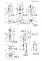
Die Figuren 1 und 2 zeigen eine erste Ausführungsform eines Auftragsgerätes 10, das ein Griffteil 12 und ein Auftragsorgan 14 aufweist. Das Griffteil 12 weist einen kreisrunden Querschnitt und eine schlitzförmige Ausnehmung 16 auf. Das Auftragsorgan 14 ist mit einem Befestigungsteil 18 ausgebildet, das einen der schlitzförmigen Ausnehmung 16 im Griffteil 12 entsprechenden Querschnitt aufweist, und das mit einem Abschnitt 20 seitlich über das Griffteil 12 übersteht. Mit dem Abschnitt 20 ist das Befestigungsteil 18 des Auftragsorgans 14 frei zugänglich. Das Befestigungsteil 18 ist mit einem Ansatz 22 ausgebildet, der eine gezahnte Oberfläche aufweist, und auf dem ein kappenförmiger Körper 24 aus einem Schaumstoff, einem Fasermaterial, oder dergleichen aufgesteckt bzw. befestigt ist.FIGS. 1 and 2 show a first embodiment of an
Die Figuren 3 und 4 zeigen eine zweite Ausführungsform eines Auftragsgerätes 10, bei dem das Griffteil 26 an der Vorderseite eine Ausnehmung 28 aufweist. In diese Ausnehmung 28, die mit Längsrippen 30 ausgebildet ist, ist das Befestigungsteil 32 eines Auftragsorganes 14 eingesteckt. Das Befestigungsteil 32 ist auch bei diesem Ausführungsbeispiel mit einem Ansatz 22 versehen, der eine gezackte Oberfläche aufweist. Mit der Bezugsziffer 24 ist auch in Figur 3 ein kappenförmiges Auftragsteil aus Schaumstoff, aus Fasermaterial, oder dergleichen bezeichnet. Wie aus Figur 4 deutlich ersichtlich ist, weist das Befestigungsteil 32 des Auftragsorganes 14 einen Querschnitt auf, der dem Querschnitt der Ausnehmung 28 im Griffteil 26 entspricht, wobei das Befestigungsteil mit Abschnitten 34 über das Griffteil 26 übersteht, die frei zugänglich sind.FIGS. 3 and 4 show a second embodiment of an
Die Figuren 5 und 6 zeigen eine dritte Ausführungsform eines Auftragsgerätes 10, bei dem das abschnittweise dargestellte Griffteil 36 eine zylindrische Ausnehmung 38 und einen das Griffteil 36 durchdringenden Schlitz 40 aufweist. Die zylindrische Ausnehmung 38 und der diametral verlaufende Schlitz 40 sind an der Vorderseite des Griffteiles 36 vorgesehen. In die zentrale Ausnehmung 38 ist das zylindrische Befestigungsteil 42 eines Auftragsorganes 14 eingesteckt. Das Auftragsorgan 14 ist bei dieser Ausführungsform des Auftragsgerätes 10 als Pinsel ausgebildet. Das Befestigungsteil 42 weist zwei Ansätze 44 auf, die aus den Schlitzen 40 herausragen, und die die frei zugänglichen Abschnitte des Befestigungsteiles 42 bilden. Damit das Auftragsorgan 14 mit seinem Befestigungsteil 42 in der Ausnehmung 38 des Griffteiles 36 gegen axiale Verschiebungen gesichert ist, weisen die beiden Schlitze 40 den Ansätzen 44 im Querschnitt entsprechende Ausnehmungen 46 auf.FIGS. 5 and 6 show a third embodiment of an
Die Figuren 7 bis 9 zeigen eine vierte Ausführungsform eines erfindungsgemäßen Auftragsgerätes 10, bei dem das Griffteil 48 an der Vorderseite ein Sackloch 50 aufweist. Das Sackloch 50 ist zur Seite des Griffteiles 48 hin durch einen Längsschlitz 52 mit der Außenseite 54 des Griffteiles 48 verbunden. Der Schlitz 52 weist eine derartige Längsausdehnung auf, daß er ein in die Ausnehmung 50 eingestecktes Befestigungsteil 56 eines Auftragsorganes 14 teilweise überlappt. In den Schlitz 52 ist ein Auswurforgan 58 eingesteckt, das entlang des Schlitzes 52 beweglich ist.FIGS. 7 to 9 show a fourth embodiment of an
Das Auswurforgan 58 ist mit Rastelementen 60 ausgebildet, mit deren Hilfe das Auswurforgan 58 im Schlitz längsbeweglich befestigt ist (sh. Figur 9).The
Die Figuren 10 bis 12 zeigen eine fünfte Ausführungsform eines Auftraggerätes 10, bei dem das Griffteil 62 am vorderen Endabschnitt mit einem kreuzförmigen Schlitz 64 ausgebildet ist. Das Auftragsorgan 14, von dem in Figur 11 das Befestigungsteil 22 mit gezackten Längsschmalseiten dargestellt ist, weist ein Befestigungsteil 66 auf, das mit Rippen versehen ist. Die Rippen bilden einen Querschnitt, der dem Querschnitt des kreuzförmigen Schlitzes 64 im Griffteil 62 entspricht. Das Befestigungsteil 66 ist mit seinen Rippen 68 in den kreuzförmigen Schlitz 64 eingesteckt, wobei die Rippen 68 über das Griffteil 62 seitlich überstehen.Die seitlich überstehenden Abschnitte der Rippen 68 des Befestigungsteiles 66 sind somit frei zugänglich, so daß das Befestigungsteil 66 des Auftragsorgans 14 aus dem kreuzförmigen Schlitz 64 in Längsrichtung des Griffteiles 62 verschoben und das Auftragsorgan 14 vom Griffteil 62 entfernt werden kann. In Figur 12 ist ein kappenförmiges Auftragsteil 24 aus einem Schaumstoff, aus einem faserförmigen Material, oder dergleichen,räumlich dargestellt. Das kappenförmige Teil 24 wird auf das mit der Bezugsziffer 22 bezeichnete Teil (sh. Figur 11) aufgesteckt und an diesem Teil 22 befestigt.FIGS. 10 to 12 show a fifth embodiment of an
Figur 13 zeigt einen vorderen Endabschnitt eines Griffteiles 62ʹ, der mit einem sternförmigen Schlitz 64ʹ ausgebildet ist. Diesem sternförmigen Schlitz 64ʹ entspricht ein nicht dargestelltes Befestigungsteil mit entsprechend orientierten Rippen.Figure 13 shows a front end portion of a handle portion 62ʹ, which is formed with a star-shaped slot 64ʹ. This star-shaped slot 64ʹ corresponds to a fastening part, not shown, with appropriately oriented ribs.
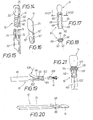
Die Figuren 14 und 15 zeigen eine andere Ausführungsform eines Auftragsgerätes 10, wobei das Auftragsorgan 14 vom abschnittweise dargestellten Griffteil 70 entfernt dargestellt ist. Das Griffteil 70 weist an seiner Vorderseite eine Ausnehmung 72 auf, die mit Rastelementen 74 versehen ist. In die Ausnehmung 72 ragen Längsrippen 76 hinein, von denen in Figur 15 nur eine sichtbar ist. Das Befestigungsteil 78 des Auftragsorganes 14 ist an zwei Seitenflächen mit einer Rippung versehen, um ein abgenutztes verbrauchtes Auftragsorgan 14 einfach vom Griffteil 70 des Auftragsgerätes 10 entfernen zu können. Das Befestigungsteil 78 weist den Längsrippen 76 formmäßig entsprechende Rillen 80 auf, von denen in Figur 14 nur eine sichtbar ist. Desgleichen weist das Befestigungsteil 78 Gegenrastelemente 82 auf, in welche die Rastelemente 74 im zusammengesteckten Zustand des Auftragsgerätes 10 einrasten. Mit der Bezugsziffer 22 ist in Figur 14 ein Befestigungsabschnitt bezeichnet, auf dem das kappenförmige Auftragsteil 24 aufgesteckt und befestigt ist.FIGS. 14 and 15 show another embodiment of an
Figur 16 zeigt ein andere Ausbildung eines Auftragsorganes 14, wobei auch in dieser Figur vom Befestigungsteil 78ʹ eine der Längsrillen 80ʹ und eines der Gegenrastelemente 82ʹ sichtbar ist. Mit der Bezugsziffer 24ʹ ist in dieser Figur ein kappenförmiges Auftragsteil aus einem Schaumstoffmaterial, aus einem Fastermaterial, oder dergleichen bezeichnet.FIG. 16 shows another embodiment of an
Die Figuren 17 und 18 zeigen eine weitere Ausführungsform eines erfindungsgemäßen Auftragsgerätes 10, bei dem das abschnittweise dargestellte Griffteil 84 eine Ausnehmung 86 in Form einer Rille aufweist.FIGS. 17 and 18 show a further embodiment of an
Die Rille 86 ist mit einer Hinterschneidung 88 ausgebildet, so daß ein Auftragsorgan 14 mit seinem Befestigungsteil 90, das einen der Rille 86 entsprechenden Querschnitt besitzt, in die rillenförmige Ausnehmung 86 eingepreßt werden kann. Das Befestigungsteil 90 weist einen Abschnitt 92 (sh. Figur 18)auf, der über das Griffteil übersteht. Durch den Abschnitt 92 ist das Befestigungsteil 90 des Auftragsorganes 14 frei zugänglich, so daß ein abgenutztes verbrauchtes Auftragsorgan 14 in einfacher Weise aus der rillenförmigen Ausnehmung 86 heraus verschoben werden kann. Anschließend kann ein neues ungebrauchtes Auftragsorgan 14 in einfacher Weise in die rillenförmige Ausnehmung 86 eingeschoben bzw. von der Seite her eingepreßt werden.The
Die Figur 19 und 20 zeigen eine Ausführungsform eines erfindungsgemäßen Auftragsgerätes 10, bei dem das Griffteil 94 mit einem Klemmbacken 96 versehen ist, der um eine Achse 98 verschwenkbar ist. Die Achse 98 ist mit dem Griffteil 94 verbunden. Zwischen dem Griffteil 94 und dem Klemmbacken 96 ist ein Federelement 100 angeordnet, das den Klemmbacken 96 an der eine Ausnehmung 102 aufweisenden Vorderseite gegen die eine Ausnehmung 104 aufweisende Vorderseite des Griffteiles 94 drückt. Die beiden Ausnehmungen 102 und 104 bilden gemeinsam eine Ausnehmung, deren Abmessungen der Abmessung des Befestigungsteiles 106 des Auftragsorganes 14 entsprechen. Durch einen Druck auf den Klemmbacken 96 in Richtung des Pfeiles 108 wird das Befestigungsteil 106 des Auftragsorgane 14 aus den Ausnehmungen 102 und 104 freigegeben, so daß das Auftragsgerät 10 in einfacher Weise mit einem neuen Auftragsorgan 14 versehen werden kann.FIGS. 19 and 20 show an embodiment of an
Figur 21 zeigt ein Auftragsgerät 10, dessen abschnittweise dargestelltes Griffteil 110 an der Vorderseite eine Ausnehmung 112 und einen umlaufenden Abschnitt mit einem Gegenrastelement 114 aufweist. Mit der Bezugsziffer 14 ist ein Auftragsorgan bezeichnet, dessen Befestigungsteil 116 einen umlaufenden Bund 118 und einen dornförmigen Ansatz 120 aufweist. Der dornförmige Ansatz 120 ist in die Ausnehmung 112 eingepaßt, und der umlaufende Bund 116 ist mit einem Rastelement ausgebildet, in das das Gegenrastelement 114 des Griffteiles 110 im zusammengesteckten Zustand des Auftragsgerätes 10 eingepaßt ist. Zur federnd nachgiebigen Ausbildung des Vorderendes des Griffteiles 110 ist ein Schlitz 122 vorgesehen.FIG. 21 shows an
Claims (15)
dadurch gekennzeichnet,
daß das Befestigungsteil (18, 28, 42, 56, 66, 78,90, 96, 116) des Auftragsorgans (14) einen Abschnitt aufweist, der in der Nachbarschaft der Vorderseite des Griffteils (12, 26, 36, 48, 62, 62ʹ 70, 84, 94, 110) von der Seite her frei zugänglich ist.1. Applicator (10) with a handle part (12, 26, 36, 48, 62, 62ʹ, 70, 92, 94, 110) and an interchangeably arranged application member (14) on the front of the handle part, which has a fastening part,
characterized,
that the fastening part (18, 28, 42, 56, 66, 78.90, 96, 116) of the application member (14) has a section which is in the vicinity of the front of the handle part (12, 26, 36, 48, 62, 62ʹ 70, 84, 94, 110) is freely accessible from the side.
dadurch gekennzeichnet,
daß das Befestigungsteil (18, 28, 42, 66, 78, 90, 116) mit einem Abschnitt über das Griffteil (12, 26, 36, 48, 62, 70, 84, 94, 110) übersteht.2. Device according to claim 1,
characterized,
that the fastening part (18, 28, 42, 66, 78, 90, 116) with a section on the handle part (12, 26, 36, 48, 62, 70, 84, 94, 110) protrudes.
dadurch gekennzeichnet,
daß das Griffteil (48) an der Vorderseite ein Sackloch (50) aufweist, daß das Befestigungsteil (56) des Auftragsorganes (14) kürzer ist als das Sackloch (50), so daß zwischen dem Boden des Sackloches (50) und dem Befestigungsteil (56) ein zentraler Hohlraum verbleibt, daß das Griffteil (48) in der Nachbarschaft der Vorderseite einen Schlitz (52) aufweist, der eine Seitenfläche des Griffteiles (48) mit dem zentralen Hohlraum verbindet, und daß der frei zugängliche Abschnitt des Befestigungsteiles (56) von einem Auswurforgan (58) gebildet ist.3. Device according to claim 1,
characterized,
that the handle part (48) has a blind hole (50) on the front, that the fastening part (56) of the application member (14) is shorter than the blind hole (50), so that between the bottom of the blind hole (50) and the fastening part ( 56) a central cavity remains that the handle part (48) in the vicinity of the front has a slot (52) which connects a side face of the handle part (48) to the central cavity, and that the freely accessible section of the fastening part (56) is formed by an ejector (58).
dadurch gekennzeichnet,
daß der in der Seitenwand des Griffteils (48) vorgesehene Schlitz (52) eine Länge aufweist, die größer ist als die Länge des zentralen Hohlraumes (50) zwischen dem Boden des Sackloches und dem Befestigungsteil (56) des Auftragsorgans.4. Apparatus according to claim 3,
characterized,
that the slot (52) provided in the side wall of the handle part (48) has a length which is greater than the length of the central cavity (50) between the bottom of the blind hole and the fastening part (56) of the application member.
dadurch gekennzeichnet,
daß das Auswurforgan (58) im Schlitz (52) des Griffteils (48) längsverschiebbar angeordnet ist.5. Apparatus according to claim 3 or 4,
characterized,
that the ejection member (58) in the slot (52) of the handle part (48) is arranged to be longitudinally displaceable.
dadurch gekennzeichnet,
daß das Griffteil (12, 26, 36, 70) an der Vorderseite eine schlitzförmige Ausnehmung (16, 28, 40, 72) aufweist, und daß das Befestigungsteil (18, 28, 42, 78) des Auftragsorgans (14) eine an die schlitzförmige Ausnehmung angepaßte Form aufweist.6. Apparatus according to claim 1,
characterized,
that the handle part (12, 26, 36, 70) has a slot-shaped recess (16, 28, 40, 72) on the front, and that the fastening part (18, 28, 42, 78) of the application member (14) one to the has slot-shaped recess adapted shape.
dadurch gekennzeichnet,
daß die Ausnehmung (64, 64ʹ) im Griffteil als Kreuzschlitz oder als sternförmiger Schlitz ausgebildet ist, und daß das Befestigungsteil (66) des Aufstragsorgans (14) Rippen (68) aufweist, deren Querschnitt dem Querschnitt der Ausnehmung (64, 64ʹ) im Griffteil (62, 62ʹ) entspricht.7. Device according to claim 6,
characterized,
that the recess (64, 64ʹ) in the handle part is designed as a cross recess or as a star-shaped slot, and that the fastening part (66) of the application member (14) has ribs (68), the cross section of which the cross section of the recess (64, 64ʹ) in the handle part (62, 62ʹ).
dadurch gekennzeichnet,
daß die das Auswurforgan bildenden Rippen (68) seitlich über das Griffteil (62) überstehen.8. Apparatus according to claim 7,
characterized,
that the ejecting ribs (68) project laterally beyond the handle part (62).
dadurch gekennzeichnet,
daß die Ausnehmung (72) im Griffteil (70) mindestens ein Rastelement (74) aufweist, und daß das Befestigungsteil (78) des Auftragsorgans (14) mit mindestens einem Gegenrastelement (82) versehen ist.9. Apparatus according to claim 6,
characterized,
that the recess (72) in the handle part (70) has at least one locking element (74), and that the fastening part (78) of the application member (14) is provided with at least one counter-locking element (82).
dadurch gekennzeichnet,
daß die Ausnehmung (86) im Griffteil (84) als Rille ausgebildet ist, die mit einer Hinterschneidung (88) versehen ist, und daß das Befestigungsteil (90) des Auftragsorganes (14) einem dem Querschnitt der Rille (86) entsprechenden Querschnitt aufweist und in die Rille (86) eingepreßt ist, wobei das Befestigungsteil (90) mit einem Abschnitt (92) seitlich aus dem Griffteil (84) vorsteht.10. Apparatus according to claim 1,
characterized,
that the recess (86) in the handle part (84) is designed as a groove which is provided with an undercut (88), and that the fastening part (90) of the application member (14) has a cross section corresponding to the cross section of the groove (86) and is pressed into the groove (86), the fastening part (90) projecting laterally with a section (92) from the grip part (84).
dadurch gekennzeichnet,
daß das Griffteil (94) eine Ausnehmung (104) und einen Klemmbacken (96) aufweist, der am Griffteil (94) um eine Achse (98) schwenkbar gelagert ist und der seitlich über das Griffteil (94) übersteht, wobei das Befestigungsteil (106) des Auftragsorganes (14) zwischen dem Griffteil (94) und dem Klemmbacken (96) festklemmbar ist.11. The device according to claim 1,
characterized,
that the handle part (94) has a recess (104) and a clamping jaw (96) which is pivotally mounted on the handle part (94) about an axis (98) and which projects laterally beyond the handle part (94), the fastening part (106 ) of the application member (14) can be clamped between the handle part (94) and the clamping jaws (96).
dadurch gekennzeichnet,
daß zwischen dem Griffteil (94) und dem Klemmbacken (96) ein Federelement (100) vorgesehen ist.12. Apparatus according to claim 11,
characterized,
that a spring element (100) is provided between the handle part (94) and the clamping jaws (96).
dadurch gekennzeichnet,
daß des Befestigungsteil (116) des Auftragsorganes (14) einen Bund (118) aufweist, der auf den vorderen Endabschnitt des Griffteils (110) aufsteckbar ist.13. Device according to claim 1,
characterized,
that the fastening part (116) of the application member (14) has a collar (118) which can be plugged onto the front end section of the handle part (110).
dadurch gekennzeichnet,
daß der Bund (118) des Befestigungsteils (116) ein Rastelement und der vordere Endabschnitt des Griffteils (110) ein Gegenrastelement (114) aufweist.14. Device according to claim 13,
characterized,
that the collar (118) of the fastening part (116) has a locking element and the front end portion of the handle part (110) has a counter-locking element (114).
dadurch gekennzeichnet,
daß das Griffteil (110) an seinem vorderen Endabschnitt eine Ausnehmung (112) und das Befestigungsteil (116) einen Einsteckansatz (120) aufweist.15. Apparatus according to claim 13 or 14,
characterized,
that the handle part (110) has a recess (112) at its front end portion and the fastening part (116) has an insertion projection (120).
Applications Claiming Priority (2)
| Application Number | Priority Date | Filing Date | Title |
|---|---|---|---|
| DE19868602547 DE8602547U1 (en) | 1986-01-31 | 1986-01-31 | Application device with an exchangeable application element |
| DE8602547U | 1986-01-31 |
Publications (2)
| Publication Number | Publication Date |
|---|---|
| EP0230955A2 true EP0230955A2 (en) | 1987-08-05 |
| EP0230955A3 EP0230955A3 (en) | 1988-08-31 |
Family
ID=6791154
Family Applications (1)
| Application Number | Title | Priority Date | Filing Date |
|---|---|---|---|
| EP87100683A Withdrawn EP0230955A3 (en) | 1986-01-31 | 1987-01-20 | Application device provided with an exchangeable applicator |
Country Status (2)
| Country | Link |
|---|---|
| EP (1) | EP0230955A3 (en) |
| DE (1) | DE8602547U1 (en) |
Cited By (3)
| Publication number | Priority date | Publication date | Assignee | Title |
|---|---|---|---|---|
| EP0327803A2 (en) * | 1988-02-09 | 1989-08-16 | Georg Karl Geka-Brush Gmbh | Disposable applying device |
| EP0681795A2 (en) * | 1994-05-10 | 1995-11-15 | Henlopen Manufacturing Co., Inc. | Material applicator with ejectable head |
| EP1481606A1 (en) * | 2003-05-27 | 2004-12-01 | Geka-Brush GmbH | Applicator for a lip cream |
Families Citing this family (4)
| Publication number | Priority date | Publication date | Assignee | Title |
|---|---|---|---|---|
| US4883079A (en) * | 1987-09-18 | 1989-11-28 | Yoshida Industry Co., Ltd. | Make-up tool and holder assembly |
| FR2624766A1 (en) * | 1987-12-21 | 1989-06-23 | Chollet Jean Louis | Brush |
| DE8907317U1 (en) * | 1989-06-15 | 1989-08-17 | Georg Karl Geka-Brush Gmbh, 8809 Bechhofen, De | |
| DE202008010815U1 (en) * | 2008-08-05 | 2009-12-31 | Metallwarenfabrik Marktoberdorf Gmbh & Co. Kg | Applicator for liquid or pasty food ingredients |
Citations (14)
| Publication number | Priority date | Publication date | Assignee | Title |
|---|---|---|---|---|
| GB115289A (en) * | 1917-05-14 | 1918-05-09 | Gilderoy Osborne Burlew | Improvements in and relating to Dental Tools for Cleaning Teeth. |
| CH103193A (en) * | 1922-09-25 | 1924-01-16 | Reichert Wilhelm | Hand broom. |
| US1506417A (en) * | 1923-10-01 | 1924-08-26 | Stanley M Donals | Tooth-cleansing device |
| DE471952C (en) * | 1926-07-27 | 1929-02-21 | Edna Sibley Tipton Geb Edna Si | Dental care device |
| FR1193019A (en) * | 1958-01-28 | 1959-10-29 | Multipurpose household tongs and cleaning or maintenance items that can be adapted to it | |
| DE1491006A1 (en) * | 1965-10-29 | 1970-01-22 | Shalom Goldstein Siegfried | Toothbrush |
| GB2035073A (en) * | 1978-11-17 | 1980-06-18 | Gray P | Tooth brush |
| EP0016564A1 (en) * | 1979-03-02 | 1980-10-01 | G.B. Kent And Sons Limited | Disposable head toothbrush |
| US4251897A (en) * | 1979-03-12 | 1981-02-24 | Naveed Alam | Disposable toothbrush |
| GB2067894A (en) * | 1980-01-24 | 1981-08-05 | Gillette Co | Toothbrush system |
| US4349961A (en) * | 1980-10-27 | 1982-09-21 | Pendleton Harlan C | Removable chisel blade |
| US4471507A (en) * | 1983-05-27 | 1984-09-18 | Marvin Schwartz | Paint brushes with detachable handles |
| DE8427383U1 (en) * | 1984-09-18 | 1985-03-14 | Georg Karl Geka-Brush Gmbh, 8802 Bechhofen | INTERCHANGEABLE COSMETIC APPLICATOR |
| FR2559656A1 (en) * | 1984-02-20 | 1985-08-23 | Doutre Jean | Toothbrush with interchangeable brushing element |
-
1986
- 1986-01-31 DE DE19868602547 patent/DE8602547U1/en not_active Expired
-
1987
- 1987-01-20 EP EP87100683A patent/EP0230955A3/en not_active Withdrawn
Patent Citations (14)
| Publication number | Priority date | Publication date | Assignee | Title |
|---|---|---|---|---|
| GB115289A (en) * | 1917-05-14 | 1918-05-09 | Gilderoy Osborne Burlew | Improvements in and relating to Dental Tools for Cleaning Teeth. |
| CH103193A (en) * | 1922-09-25 | 1924-01-16 | Reichert Wilhelm | Hand broom. |
| US1506417A (en) * | 1923-10-01 | 1924-08-26 | Stanley M Donals | Tooth-cleansing device |
| DE471952C (en) * | 1926-07-27 | 1929-02-21 | Edna Sibley Tipton Geb Edna Si | Dental care device |
| FR1193019A (en) * | 1958-01-28 | 1959-10-29 | Multipurpose household tongs and cleaning or maintenance items that can be adapted to it | |
| DE1491006A1 (en) * | 1965-10-29 | 1970-01-22 | Shalom Goldstein Siegfried | Toothbrush |
| GB2035073A (en) * | 1978-11-17 | 1980-06-18 | Gray P | Tooth brush |
| EP0016564A1 (en) * | 1979-03-02 | 1980-10-01 | G.B. Kent And Sons Limited | Disposable head toothbrush |
| US4251897A (en) * | 1979-03-12 | 1981-02-24 | Naveed Alam | Disposable toothbrush |
| GB2067894A (en) * | 1980-01-24 | 1981-08-05 | Gillette Co | Toothbrush system |
| US4349961A (en) * | 1980-10-27 | 1982-09-21 | Pendleton Harlan C | Removable chisel blade |
| US4471507A (en) * | 1983-05-27 | 1984-09-18 | Marvin Schwartz | Paint brushes with detachable handles |
| FR2559656A1 (en) * | 1984-02-20 | 1985-08-23 | Doutre Jean | Toothbrush with interchangeable brushing element |
| DE8427383U1 (en) * | 1984-09-18 | 1985-03-14 | Georg Karl Geka-Brush Gmbh, 8802 Bechhofen | INTERCHANGEABLE COSMETIC APPLICATOR |
Cited By (5)
| Publication number | Priority date | Publication date | Assignee | Title |
|---|---|---|---|---|
| EP0327803A2 (en) * | 1988-02-09 | 1989-08-16 | Georg Karl Geka-Brush Gmbh | Disposable applying device |
| EP0327803A3 (en) * | 1988-02-09 | 1990-05-23 | Georg Karl Geka-Brush Gmbh | Disposable applying device |
| EP0681795A2 (en) * | 1994-05-10 | 1995-11-15 | Henlopen Manufacturing Co., Inc. | Material applicator with ejectable head |
| EP0681795A3 (en) * | 1994-05-10 | 1996-05-01 | Henlopen Mfg Co Inc | Material applicator with ejectable head. |
| EP1481606A1 (en) * | 2003-05-27 | 2004-12-01 | Geka-Brush GmbH | Applicator for a lip cream |
Also Published As
| Publication number | Publication date |
|---|---|
| EP0230955A3 (en) | 1988-08-31 |
| DE8602547U1 (en) | 1986-03-13 |
Similar Documents
| Publication | Publication Date | Title |
|---|---|---|
| EP2799023A1 (en) | Screwdriver for bone screws | |
| WO1998010704A1 (en) | Multicomponent tissue adhesive application device and holder for such device | |
| EP0384026A2 (en) | Device for applying cosmetics | |
| EP0757525A1 (en) | Refillable container for delivering a spreading compound, in particular an adhesive compound | |
| EP1488894A1 (en) | Razor cartridge | |
| EP0841098B1 (en) | Device for discharging a fluent mass | |
| DE8423218U1 (en) | DEVICE FOR CLEANING LIGHTWAVE CONNECTOR PARTS | |
| EP3416751B1 (en) | Device for applying adhesive and/or sealant | |
| DE4116581C2 (en) | ||
| EP0230955A2 (en) | Application device provided with an exchangeable applicator | |
| DE2606939B2 (en) | Writing implement for thin lead | |
| DE3832694C2 (en) | ||
| EP2103558A2 (en) | Compact adhesive tape dispenser | |
| EP0413143A1 (en) | Razor head, especially a blade unit of a wet-razor | |
| DE4314173A1 (en) | Connecting element for releasably connecting a piece of equipment to a handle (shaft) | |
| EP0026277A1 (en) | Ball-point pen | |
| DE4429063A1 (en) | Tool with handle esp. for household knife | |
| DE3042035C2 (en) | Writing, drawing, painting or the like. Device with a replaceable cartridge | |
| WO1994025223A1 (en) | Joining element for detachably joining a tool to a handle | |
| DE19707620B4 (en) | Surgical scalpel | |
| DE69905359T2 (en) | CROSS DEVICE | |
| WO1996041702A1 (en) | Angled screwdriver | |
| DE2532626B2 (en) | DEVICE FOR REPLACING MINES OF A WRITING DEVICE | |
| EP0516915B1 (en) | Piston filling device for a writing implement, especially for a fountain pen | |
| DE19815667A1 (en) | Face powder applicator works precisely independent of condition of powder |
Legal Events
| Date | Code | Title | Description |
|---|---|---|---|
| PUAI | Public reference made under article 153(3) epc to a published international application that has entered the european phase |
Free format text: ORIGINAL CODE: 0009012 |
|
| AK | Designated contracting states |
Kind code of ref document: A2 Designated state(s): AT BE CH DE ES FR GB GR IT LI LU NL SE |
|
| PUAL | Search report despatched |
Free format text: ORIGINAL CODE: 0009013 |
|
| AK | Designated contracting states |
Kind code of ref document: A3 Designated state(s): AT BE CH DE ES FR GB GR IT LI LU NL SE |
|
| STAA | Information on the status of an ep patent application or granted ep patent |
Free format text: STATUS: THE APPLICATION IS DEEMED TO BE WITHDRAWN |
|
| 18D | Application deemed to be withdrawn |
Effective date: 19890301 |
|
| RIN1 | Information on inventor provided before grant (corrected) |
Inventor name: DER ERFINDER HAT AUF SEINE NENNUNG VERZICHTET. |