EP0234928A2 - Optical fiber apparatus - Google Patents
Optical fiber apparatus Download PDFInfo
- Publication number
- EP0234928A2 EP0234928A2 EP87301632A EP87301632A EP0234928A2 EP 0234928 A2 EP0234928 A2 EP 0234928A2 EP 87301632 A EP87301632 A EP 87301632A EP 87301632 A EP87301632 A EP 87301632A EP 0234928 A2 EP0234928 A2 EP 0234928A2
- Authority
- EP
- European Patent Office
- Prior art keywords
- cable
- fluid
- hole
- light
- optical fiber
- Prior art date
- Legal status (The legal status is an assumption and is not a legal conclusion. Google has not performed a legal analysis and makes no representation as to the accuracy of the status listed.)
- Ceased
Links
Images
Classifications
-
- G—PHYSICS
- G02—OPTICS
- G02B—OPTICAL ELEMENTS, SYSTEMS OR APPARATUS
- G02B1/00—Optical elements characterised by the material of which they are made; Optical coatings for optical elements
-
- G—PHYSICS
- G01—MEASURING; TESTING
- G01N—INVESTIGATING OR ANALYSING MATERIALS BY DETERMINING THEIR CHEMICAL OR PHYSICAL PROPERTIES
- G01N21/00—Investigating or analysing materials by the use of optical means, i.e. using sub-millimetre waves, infrared, visible or ultraviolet light
- G01N21/75—Systems in which material is subjected to a chemical reaction, the progress or the result of the reaction being investigated
- G01N21/77—Systems in which material is subjected to a chemical reaction, the progress or the result of the reaction being investigated by observing the effect on a chemical indicator
- G01N21/7703—Systems in which material is subjected to a chemical reaction, the progress or the result of the reaction being investigated by observing the effect on a chemical indicator using reagent-clad optical fibres or optical waveguides
-
- A—HUMAN NECESSITIES
- A61—MEDICAL OR VETERINARY SCIENCE; HYGIENE
- A61B—DIAGNOSIS; SURGERY; IDENTIFICATION
- A61B5/00—Measuring for diagnostic purposes; Identification of persons
- A61B5/0059—Measuring for diagnostic purposes; Identification of persons using light, e.g. diagnosis by transillumination, diascopy, fluorescence
- A61B5/0082—Measuring for diagnostic purposes; Identification of persons using light, e.g. diagnosis by transillumination, diascopy, fluorescence adapted for particular medical purposes
- A61B5/0084—Measuring for diagnostic purposes; Identification of persons using light, e.g. diagnosis by transillumination, diascopy, fluorescence adapted for particular medical purposes for introduction into the body, e.g. by catheters
-
- G—PHYSICS
- G01—MEASURING; TESTING
- G01N—INVESTIGATING OR ANALYSING MATERIALS BY DETERMINING THEIR CHEMICAL OR PHYSICAL PROPERTIES
- G01N21/00—Investigating or analysing materials by the use of optical means, i.e. using sub-millimetre waves, infrared, visible or ultraviolet light
- G01N21/75—Systems in which material is subjected to a chemical reaction, the progress or the result of the reaction being investigated
- G01N21/77—Systems in which material is subjected to a chemical reaction, the progress or the result of the reaction being investigated by observing the effect on a chemical indicator
- G01N21/7703—Systems in which material is subjected to a chemical reaction, the progress or the result of the reaction being investigated by observing the effect on a chemical indicator using reagent-clad optical fibres or optical waveguides
- G01N2021/7706—Reagent provision
Definitions
- the present invention relates to an optical fiber apparatus for transmitting an incident light signal toward a first end, and for transmitting a returning light signal toward a second end that is indicative of a specified characteristic of the environment in which the first end is positioned. More particularly, the present invention relates to an optical fiber apparatus for insertion into a fluid to be analyzed to measure a specified characteristic of that fluid.
- Known sensing systems using optical fibers to transmit light indicative of a specified characteristic of a fluid have generally had a chamber attached to the end of the optic cable.
- This chamber normally contains one or more receptor sites for interacting with the fluid to be analyzed.
- the chamber interior is normally isolated from the fluid by a selectively porous membrane. This membrane is designed to allow the particular constitutent of the fluid that is to be analyzed to enter the interior of the chamber, and to exclude all other unwanted portions. Examples of known sensing systems are found in U.S. Patents 4,357,l06; 4,344,438; and Re 3l,879.
- Another problem with the known sensing systems is that the chamber is difficult to attach securely to the end of the cable.
- Many of the sensing systems are designed to be used as a catheter for insertion into a blood vessel of a body. This use as a catheter requires that the chamber be extremely small. The small size of the chamber makes attachment to the small optic cable very difficult. Furthermore, the failure of secure attachment leads to the chamber becoming disengaged from the optic fiber, with obvious problems resulting.
- One object of the present invention is to provide an optical fiber apparatus for transmitting an incident light signal toward a first end, and for transmitting a returning light signal toward a second end that is indicative of a specified characteristic of the contents of a fluid that overcomes the deficiencies of the prior art.
- Another object of the present invention is to provide an optical fiber apparatus that does not require a reactive chamber to be attached to the end of the optic cable, thereby eliminating any chance of damage to the chamber.
- Still another object of the present invention is to provide an optical fiber apparatus that eliminates the problems associated with attaching a chamber to the end of the optic cable.
- an optical fiber apparatus for transmitting an incident light signal toward the first end of the apparatus which is situated inside a fluid.
- the apparatus also carries a returning signal toward a second end that is situated outside the fluid.
- the returning signal is indicative of a specified characteristic of the contents of the fluid.
- the apparatus includes a light conductive cable capable of transmitting light, with a hole formed in the first end of the cable.
- a reactive element is inserted totally into the hole in the end of the cable. The reactive element reacts with the fluid being analyzed to alter a property of the returning light as compared to the incident light. The returning light is thereby indicative of a specified characteristic of that fluid.
- the first end of the cable may be coated with a selectively or highly reflective material.
- a selectively or highly reflective material is that more incident light is reflected through the reactive element and transmitted toward the second end of the cable.
- substantially the entire surface of the cable is coated with a protective sheath.
- a protective sheath is that the cable is better adapted to be used as a catheter for insertion into a blood vessel in a body.
- Another advantage of the protective sheath is that more light is transmitted through the cable because the protective sheath tends to prevent light loss from the cable.
- the hole in the end of the cable is formed by a method that is fast and accurate, such as, for example, by laser machining, microdrilling, or by chemical etching.
- a method that is fast and accurate such as, for example, by laser machining, microdrilling, or by chemical etching.
- One advantage of this method of forming the hole is that the hole is accurately formed.
- Another advantage of this method is that a multiplicity of cables can be so formed in succession, and to identical specifications, thus permitting the cables to be mass-produced.
- the reactive elements consist of specific binding agents (e.g. antibodies) for a ligand of interest, possibly in combination with a ligand analog.
- a ligand analog may consist of a ligand labeled with a fluorescent substance whereby a change in the quantum yield of said label occurs when ligand analog is bound to the specific binding agent.
- the ligand analog is competitively displaced from the specific binding agent, resulting in a change in the emission intensity.
- One feature of the present invention is that the reactive element is contained entirely within the hole in the operative end of the cable.
- One advantage of this feature is that the reactive element is protected from possible damage through contact with foreign objects.
- Another advantage of this feature is that the cable has a uniform diameter throughout its length. The reactive element, by not being fixed to the outer surface of the cable, does not create an area of increased diameter at the sensing tip. This allows the cable to be wholly encased within a smooth biocompatible coating, thereby reducing the chance of thrombogenicity which could otherwise occur. This permits the cable to be more easily used as a catheter, especially in the smaller sized blood vessels.
- the first end of the cable is planar, with the plane being orthogonal to the longitudinal axis of the cable, and the hole extends axially inwardly into the cable and is concentric with the outer circumference of the cable.
- the apparatus of the present invention is not limited to this configuration of either the hole, or the first end of the cable.
- the hole need not be either radially or axially symmetrical with respect to the outer circumference of the cable.
- the hole may be formed in the first end of the cable such that it is not centrally located in the first end, and the hole may extend inwardly at an angle to the longitudinal axis of the cable.
- more than one hole may be formed in the first end of the cable with a different reactive element placed in each hole.
- the first end of the cable may also be planar, with the plane at an angle other than 90° to the longitudinal axis of the cable.
- the hole may be in the first end with its axis parallel to the longitudinal axis of the cable, or the hole may be in the outer surface of the cable, near the first end, with its axis perpendicular to the longitudinal axis of the cable.
- the hole may also be in the form of an annular, circumferentially extending channel in the outer surface of the cable near the first end.
- the first end of the cable may be frusto-conically shaped, or parabolically shaped, with the hole extending axially inwardly with its axis parallel to the longitudinal axis of the cable.
- the optical fiber apparatus l0 includes an optical cable l2 capable of transmitting light.
- the optical cable l2 has a first end l4 that is planar and oriented to be perpendicular to the longitudinal axis of the cable l2.
- the optical cable l2 also has an outer surface l6 and an inner core l7.
- the core l7 is lined for glass but can be constructed of any material which would function as required to achieve the necessary optical performance.
- a hole l8 is formed in the center of the first end l4 of the cable l2, either by laser machining, by microdrilling, or by other equivalent means such that the hole l8 is generally concentric with the circumference of the first end l4.
- the hole l8 has a diameter approximately one-third the diameter of the cable l2.
- the depth of the hole l8 is approximately equal to the diameter of the hole l8.
- a reactive element 20 is inserted into the hole l8.
- the reactive element 20 is contained totally within the hole l8.
- the hole l8 may optionally be covered with a semi-permeable membrane (not shown) whose porosity is chosen so as to confine the reactive element 20 within the hole l8 and prevent the admission into the hole l8 of substances larger than the analyte.
- the reactive element 20 is spherical shaped.
- the size of the reactive element can range from several hundred angstroms to several microns. It is understood that the reactive element 20 may have other shapes including being a disperse matrix of a polymer or a liquid, with the restriction being that the entire reactive element is preferably contained totally within the hole l8.
- a reflective coating 22 may be layered over the first end l4 of the cable l2, with the reflective coating 22 extending axially inwardly from the first end l4 over a portion of the outer surface l6 of the cable l2.
- the reflective coating 22 is required when light will pass through the reactive element 20 and be reflected from the first end l4 of the cable l2 (absorbance).
- the reflective coating 22 is helpful where the reactive element 20 absorbs and retransmits the light (fluorescence).
- the reflective coating 22 is not used when light is reflected off of the reactive element 20 toward the second end of the cable l2 (light-scattering).
- the reflective coating 22 may be layered directly over the outer surface l6, as shown in Fig.
- the outer fiber jacket 24 may be stripped back, and the reflective coating 22 layered over the exposed inner core l7 of the cable l2.
- the reflective coating 22 should not cover hole l8 as the reactive element 20 would be prevented from reacting with the fluid environment in which the first end is situated.
- the reflective coating 22 may be constructed to be wavelength specific, whereby certain wavelengths of light are reflected and others allowed to be transmitted out of the first end l4. This significantly improves the ability of the system to quantify the desired information by reducing or eliminating wavelengths of light passing through but not interacting with the reactive element 20.
- the reflective coating 22 may be made wavelength specific by using conventional optical filtering techniques.
- the optical fiber apparatus l0 can be prepared in the following manner. Referring to Figs. 3a, 3b, 3c, and 3d, it is first assumed that a reflective coating 22 is not to be used. The optic cable l2 is microdrilled to form the hole l8, as shown in Fig. 3b. The reactive element 20 is then placed in the hole l8 so that the reactive element 20 is contained totally within the hole l8, as shown in Fig. 3c. A protective sheath 26 is then applied over substantially the entire outer surface l6 of the cable l2, as shown in Fig. 3d, to protect the apparatus l0. If the optical fiber apparatus l0 is to be used as a catheter for insertion into the body, the protective sheath 26 is chosen for its biocompatibility as well as its protective ability. The selection of suitable materials is within the skill of persons familiar with body invasive instrumentation.
- the reflective coating 22 is to be applied to the cable l2, the reflective coating 22 is applied as a first step before the cable l2 is microdrilled. If it is necessary to strip off the outer fiber jacket 24, the stripping is performed first, with the reflective coating 22 then applied, followed by the step of microdrilling. The steps described previously, subsequent to the microdrilling, would remain the same, whether a reflective coating 22 is used or not.
- the sensing system 28 includes the optical fiber apparatus l0, a beam splitter 30, a light source 32, a light receiver 34, and an analyzer 36.
- the optical fiber apparatus l0 portion of the sensing system 28 is inserted into the body, for example, a blood vessel of the body, in a conventional manner.
- the reactive element 20 interacts with the contents of the body, which for illustrative purposes will be considered to be blood in a blood vessel of the body.
- This interaction between the blood and the reactive element 20 changes a specific property of the reactive element 20 in a conventional manner, the reaction of which is not part of the present invention.
- the reactive element 20 is chosen such that changes in the specific characteristic of the blood, or other fluid that is to be analyzed, will be indicated by changes in the property of the reactive element 20.
- Incident light 38 from the light source 32 Passes through the beam splitter 30, and is transmitted in a conventional manner toward the first end l4 of the optic fiber l2, as best shown in Fig. 5.
- the optional reflective coating 22 functions to minimize any loss of the incident light 38 through the first end l4.
- the incident light 38 may be reflected by the reflective coating 22, and travel through the hole l8 and contained reactive element 20.
- the incident light 38 may be reflected from the reactive element 20 or may be absorbed by, and retransmitted from, the reactive element 20 at a wavelength generally equal to or greater than that of the incident light 38, corresponding to the well-known phenomena of absorbance, light-scattering, and fluorescence.
- a property of the light 38 is altered in a conventional manner.
- the amount of alteration or change in a property of the incident light 38 is dictated by the change in the property of the reactive element 20 as it interacts with the blood, or other fluid of the body, as described previously.
- the change in the incident light 38 is a function of the reaction between the reactive element 20 and the fluid to be analyzed. As discussed previously, this reaction between the reactive element 20 and the fluid is indicative of a specific characteristic of the fluid. Therefore, the change in the incident light 38 is indicative of the specific characteristic of the fluid to be analyzed.
- the altered incident light 38 is transmitted away from the first end l4 of the cable l2, and will be referred to as the returning light 39, 40, 4l, as shown in Fig. 2.
- Returning light 39 represents the light that is reflected from the reactive element 20.
- Returning light 40 represents the light that passes through the reactive element 20.
- Returning light 4l represents the light that is absorbed by, and retransmitted from, the reactive element 20 at a wavelength equal to or greater than that of the incident light 38. It will be understood that the returning light 39, 40, 4l may also include a portion of the incident light 38 that is reflected from the reflective coating 22 if the reflective coating 22 is applied to the first end l4 of the cable l2.
- the returning light 40 passes through the beam splitter 30, which separates the incident light 38 from the returning light 40 in a conventional manner.
- the returning light 40 then passes through the light receiver 34 to the analyzer 36.
- the analyzer 36 compares the returning light 40 with the incident light 38 in a conventional manner, and measures the desired specific characteristic of the fluid. It is understood that the present invention is not limited to use inside the body.
- the fluid to be tested for example blood, may be withdrawn from the body conventionally, and the optical fiber apparatus l0 used to analyze this drawn blood.
- the specific characteristic may be, but is not limited to, the presence of drugs, level of metabolites, pressure, temperature and dissolved gases.
- FIG. 6 shows the optic cable l2 having a planar first end l4, with the plane being at an angle other than 90° with respect to the longitudinal axis of the cable l2, for example, at the polarizing angle.
- the hole l8 is concentric with the circumference of the outer surface l6 of the cable l2, and extends longitudinally inwardly.
- the reactive element 20 is shown as a disperse element disposed within the hole l8, rather than as a spherical element as shown in Figs. l and 2.
- Fig. 7 shows the optic cable l2 having a frustoconical shaped first end l4.
- the hole l8 is concentric with the circumference of the outer surface l6 of the cable l2 and extends longitudinally inwardly.
- Fig. 8 shows the optic cable l2 having a parabolically shaped first end l4.
- the hole l8 is concentric with the circumference of the outer surface l6 of the cable l2 and extends longitudinally inwardly.
- Fig. 9 shows the optic cable l2 having a planar first end l4, with the plane being at an angle other than 90° with respect to the longitudinal axis of the cable l2, similar to the cable l2 shown in Fig. 6. However, the hole l8 extends radially inwardly from the outer surface l6 at a location near the first end l4.
- Fig. l0 shows the optic cable l2 having a planar first end l4, with the plane being at an angle other than 90° with respect to the longitudinal axis of the cable l2.
- the hole l8 in this embodiment is an annular groove that extends circumferentially around the optic cable l2 and extends radially inwardly from the outer surface l6 of the cable l2.
- Fig. ll shows the optic cable l2 having a planar first end l4, with the plane being substantially perpendicular to the longitudinal axis of the cable l2.
- the hole l8 in the first end l4 extends through the reflective coating 22 and is not concentric with the outer surface l6 of the cable l2 and extends inwardly at an angle to the longitudinal axis of the cable l2.
- An abrasion-resistant coating 60 is shown covering the reflective coating 22.
- the abrasion-resistant coating 60 is designed to protect the first end l4 and the reflective coating 22.
- the abrasion-resistant coating 60 is chosen for its biocompatibility as well as for its protective ability.
- Figs. l2 and l3 show the optic cable l2 having a planar first end l4, with the plane being substantially perpendicular to the longitudinal axis of the cable l2.
- Five holes l8 are formed in the first end l4, with the holes spaced about the surface of the first end l4.
- the five holes l8 are provided to allow different types of reactive elements, illustratively reactive elements 50, 52, 54, 56, 58, to be included in the optic cable l2.
- Each reactive element 50, 52, 54, 56, 58 Produces a different interaction with the incident light 38, thereby enabling the light receiver 34 and the analyzer 36 to spectrally analyze more than one characteristic of the body contents at the same time using only a single optic cable l2.
- the light source 32, the light receiver 34, and the analyzer 36 will necessarily be more complex components because of the requirement to demultiplex the information in the returning light 39, 40, 4l.
Abstract
Description
- The present invention relates to an optical fiber apparatus for transmitting an incident light signal toward a first end, and for transmitting a returning light signal toward a second end that is indicative of a specified characteristic of the environment in which the first end is positioned. More particularly, the present invention relates to an optical fiber apparatus for insertion into a fluid to be analyzed to measure a specified characteristic of that fluid.
- Known sensing systems using optical fibers to transmit light indicative of a specified characteristic of a fluid have generally had a chamber attached to the end of the optic cable. This chamber normally contains one or more receptor sites for interacting with the fluid to be analyzed. The chamber interior is normally isolated from the fluid by a selectively porous membrane. This membrane is designed to allow the particular constitutent of the fluid that is to be analyzed to enter the interior of the chamber, and to exclude all other unwanted portions. Examples of known sensing systems are found in U.S. Patents 4,357,l06; 4,344,438; and Re 3l,879.
- One problem with the known sensing systems of the type described is that the chamber attached to the end of the optic cable is prone to physical damage. Such known chambers are delicate because they are situated as an external appendage located on the end of the optic cable. Any mishandling of the cable can easily result in damage to the delicate chamber.
- Another problem with the known sensing systems is that the chamber is difficult to attach securely to the end of the cable. Many of the sensing systems are designed to be used as a catheter for insertion into a blood vessel of a body. This use as a catheter requires that the chamber be extremely small. The small size of the chamber makes attachment to the small optic cable very difficult. Furthermore, the failure of secure attachment leads to the chamber becoming disengaged from the optic fiber, with obvious problems resulting.
- One object of the present invention is to provide an optical fiber apparatus for transmitting an incident light signal toward a first end, and for transmitting a returning light signal toward a second end that is indicative of a specified characteristic of the contents of a fluid that overcomes the deficiencies of the prior art.
- Another object of the present invention is to provide an optical fiber apparatus that does not require a reactive chamber to be attached to the end of the optic cable, thereby eliminating any chance of damage to the chamber.
- Still another object of the present invention is to provide an optical fiber apparatus that eliminates the problems associated with attaching a chamber to the end of the optic cable.
- According to the present invention, an optical fiber apparatus is provided for transmitting an incident light signal toward the first end of the apparatus which is situated inside a fluid. The apparatus also carries a returning signal toward a second end that is situated outside the fluid. The returning signal is indicative of a specified characteristic of the contents of the fluid. The apparatus includes a light conductive cable capable of transmitting light, with a hole formed in the first end of the cable. A reactive element is inserted totally into the hole in the end of the cable. The reactive element reacts with the fluid being analyzed to alter a property of the returning light as compared to the incident light. The returning light is thereby indicative of a specified characteristic of that fluid.
- In some preferred embodiments of the present invention, the first end of the cable may be coated with a selectively or highly reflective material. One advantage of the reflective coating is that more incident light is reflected through the reactive element and transmitted toward the second end of the cable.
- Also in preferred embodiments of the present invention, substantially the entire surface of the cable is coated with a protective sheath. One advantage of the protective sheath is that the cable is better adapted to be used as a catheter for insertion into a blood vessel in a body. Another advantage of the protective sheath is that more light is transmitted through the cable because the protective sheath tends to prevent light loss from the cable.
- Also in preferred embodiments of the present invention, the hole in the end of the cable is formed by a method that is fast and accurate, such as, for example, by laser machining, microdrilling, or by chemical etching. One advantage of this method of forming the hole is that the hole is accurately formed. Another advantage of this method is that a multiplicity of cables can be so formed in succession, and to identical specifications, thus permitting the cables to be mass-produced.
- Also in preferred embodiments of the present invention, the reactive elements consist of specific binding agents (e.g. antibodies) for a ligand of interest, possibly in combination with a ligand analog. For example, a ligand analog may consist of a ligand labeled with a fluorescent substance whereby a change in the quantum yield of said label occurs when ligand analog is bound to the specific binding agent. In the Presence of non-labeled ligand (provided by the fluid being analyzed) the ligand analog is competitively displaced from the specific binding agent, resulting in a change in the emission intensity.
- One feature of the present invention is that the reactive element is contained entirely within the hole in the operative end of the cable. One advantage of this feature is that the reactive element is protected from possible damage through contact with foreign objects. Another advantage of this feature is that the cable has a uniform diameter throughout its length. The reactive element, by not being fixed to the outer surface of the cable, does not create an area of increased diameter at the sensing tip. This allows the cable to be wholly encased within a smooth biocompatible coating, thereby reducing the chance of thrombogenicity which could otherwise occur. This permits the cable to be more easily used as a catheter, especially in the smaller sized blood vessels.
- In one embodiment of the present invention, the first end of the cable is planar, with the plane being orthogonal to the longitudinal axis of the cable, and the hole extends axially inwardly into the cable and is concentric with the outer circumference of the cable. However, the apparatus of the present invention is not limited to this configuration of either the hole, or the first end of the cable.
- For example, the hole need not be either radially or axially symmetrical with respect to the outer circumference of the cable. Thus, the hole may be formed in the first end of the cable such that it is not centrally located in the first end, and the hole may extend inwardly at an angle to the longitudinal axis of the cable. Also, more than one hole may be formed in the first end of the cable with a different reactive element placed in each hole.
- The first end of the cable may also be planar, with the plane at an angle other than 90° to the longitudinal axis of the cable. With this configuration, the hole may be in the first end with its axis parallel to the longitudinal axis of the cable, or the hole may be in the outer surface of the cable, near the first end, with its axis perpendicular to the longitudinal axis of the cable. The hole may also be in the form of an annular, circumferentially extending channel in the outer surface of the cable near the first end.
- Furthermore, the first end of the cable may be frusto-conically shaped, or parabolically shaped, with the hole extending axially inwardly with its axis parallel to the longitudinal axis of the cable.
- Additional objects, features, and advantages of the invention will become apparent to those skilled in the art upon consideration of the following detailed description of preferred embodiments exemplifying the best mode of carrying out the invention as presently perceived. The detailed description particularly refers to the accompanying figures in which:
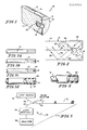
- Fig. l is an isometric view in section of the optical fiber apparatus;
- Fig. 2 is a diagrammatic illustration of the optical fiber apparatus schematically showing a path of travel of the light;
- Figs. 3a-3d are side views with portions broken away of the ends of the optical fiber apparatus illustrating the steps of forming the optical fiber apparatus;
- Fig. 4 is a side view with portions broken away illustrating the final step of forming the optical fiber apparatus using a modified optic cable;
- Fig. 5 is a diagrammatic illustration of an optical fiber sensing system including the optical fiber apparatus of Fig. l;
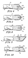
- Fig 6 is a side view with portions broken away of the end of the optical fiber apparatus illustrating one modification;
- Fig. 7 is a side view with portions broken away of the end of the optical fiber apparatus illustrating another modification to the optical fiber apparatus;
- Fig. 8 is a side view with portions broken away of the end of the optical fiber apparatus illustrating another modification to the optical fiber apparatus;
- Fig. 9 is a side view with portions broken away of the end of the optical fiber apparatus illustrating another modification to the optical fiber apparatus;
- Fig l0 is a side view with portions broken away of the end of the optical fiber apparatus illustrating another modification to the optical fiber apparatus.
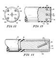
- Fig. ll is a side view with portions broken away of the end of the optical fiber apparatus illustrating another modification to the optical fiber apparatus;
- Fig. l2 is an end view of the optical fiber apparatus illustrating another modification to the optical fiber apparatus;
- Fig. l3 is a side view with portions broken away of the end of the optical fiber apparatus of Fig. l2.
- Referring now to the drawings, an optical fiber apparatus l0 is shown in Fig. l. The optical fiber apparatus l0 includes an optical cable l2 capable of transmitting light. The optical cable l2 has a first end l4 that is planar and oriented to be perpendicular to the longitudinal axis of the cable l2. The optical cable l2 also has an outer surface l6 and an inner core l7. The core l7 is lined for glass but can be constructed of any material which would function as required to achieve the necessary optical performance.
- A hole l8 is formed in the center of the first end l4 of the cable l2, either by laser machining, by microdrilling, or by other equivalent means such that the hole l8 is generally concentric with the circumference of the first end l4. Illustratively, the hole l8 has a diameter approximately one-third the diameter of the cable l2. The depth of the hole l8 is approximately equal to the diameter of the hole l8.
- A
reactive element 20 is inserted into the hole l8. Thereactive element 20 is contained totally within the hole l8. The hole l8 may optionally be covered with a semi-permeable membrane (not shown) whose porosity is chosen so as to confine thereactive element 20 within the hole l8 and prevent the admission into the hole l8 of substances larger than the analyte. As shown, thereactive element 20 is spherical shaped. The size of the reactive element can range from several hundred angstroms to several microns. It is understood that thereactive element 20 may have other shapes including being a disperse matrix of a polymer or a liquid, with the restriction being that the entire reactive element is preferably contained totally within the hole l8. - A
reflective coating 22 may be layered over the first end l4 of the cable l2, with thereflective coating 22 extending axially inwardly from the first end l4 over a portion of the outer surface l6 of the cable l2. Thereflective coating 22 is required when light will pass through thereactive element 20 and be reflected from the first end l4 of the cable l2 (absorbance). Thereflective coating 22 is helpful where thereactive element 20 absorbs and retransmits the light (fluorescence). Thereflective coating 22 is not used when light is reflected off of thereactive element 20 toward the second end of the cable l2 (light-scattering). Thereflective coating 22 may be layered directly over the outer surface l6, as shown in Fig. l, or, if the optic cable l2 has anouter fiber jacket 24, as shown in Fig. 4, theouter fiber jacket 24 may be stripped back, and thereflective coating 22 layered over the exposed inner core l7 of the cable l2. Thereflective coating 22 should not cover hole l8 as thereactive element 20 would be prevented from reacting with the fluid environment in which the first end is situated. - In addition, the
reflective coating 22 may be constructed to be wavelength specific, whereby certain wavelengths of light are reflected and others allowed to be transmitted out of the first end l4. This significantly improves the ability of the system to quantify the desired information by reducing or eliminating wavelengths of light passing through but not interacting with thereactive element 20. Thereflective coating 22 may be made wavelength specific by using conventional optical filtering techniques. - The optical fiber apparatus l0 can be prepared in the following manner. Referring to Figs. 3a, 3b, 3c, and 3d, it is first assumed that a
reflective coating 22 is not to be used. The optic cable l2 is microdrilled to form the hole l8, as shown in Fig. 3b. Thereactive element 20 is then placed in the hole l8 so that thereactive element 20 is contained totally within the hole l8, as shown in Fig. 3c. Aprotective sheath 26 is then applied over substantially the entire outer surface l6 of the cable l2, as shown in Fig. 3d, to protect the apparatus l0. If the optical fiber apparatus l0 is to be used as a catheter for insertion into the body, theprotective sheath 26 is chosen for its biocompatibility as well as its protective ability. The selection of suitable materials is within the skill of persons familiar with body invasive instrumentation. - If the
reflective coating 22 is to be applied to the cable l2, thereflective coating 22 is applied as a first step before the cable l2 is microdrilled. If it is necessary to strip off theouter fiber jacket 24, the stripping is performed first, with thereflective coating 22 then applied, followed by the step of microdrilling. The steps described previously, subsequent to the microdrilling, would remain the same, whether areflective coating 22 is used or not. - Referring now to Fig. 5, an optical
fiber sensing system 28 is shown. Thesensing system 28 includes the optical fiber apparatus l0, abeam splitter 30, alight source 32, alight receiver 34, and ananalyzer 36. - In operation, the optical fiber apparatus l0 portion of the
sensing system 28 is inserted into the body, for example, a blood vessel of the body, in a conventional manner. Thereactive element 20 interacts with the contents of the body, which for illustrative purposes will be considered to be blood in a blood vessel of the body. This interaction between the blood and thereactive element 20 changes a specific property of thereactive element 20 in a conventional manner, the reaction of which is not part of the present invention. Thereactive element 20 is chosen such that changes in the specific characteristic of the blood, or other fluid that is to be analyzed, will be indicated by changes in the property of thereactive element 20. - Incident light 38 from the
light source 32 Passes through thebeam splitter 30, and is transmitted in a conventional manner toward the first end l4 of the optic fiber l2, as best shown in Fig. 5. As theincident light 38 nears the first end l4 of the optic fiber l2, the optionalreflective coating 22 functions to minimize any loss of the incident light 38 through the first end l4. - Referring now to Fig. 2, the
incident light 38 may be reflected by thereflective coating 22, and travel through the hole l8 and containedreactive element 20. In addition, theincident light 38 may be reflected from thereactive element 20 or may be absorbed by, and retransmitted from, thereactive element 20 at a wavelength generally equal to or greater than that of theincident light 38, corresponding to the well-known phenomena of absorbance, light-scattering, and fluorescence. As the incident light 38 passes through thereactive element 20, or is reflected from thereactive element 20, or is absorbed by and retransmitted from thereactive element 20, a property of the light 38 is altered in a conventional manner. - The amount of alteration or change in a property of the
incident light 38 is dictated by the change in the property of thereactive element 20 as it interacts with the blood, or other fluid of the body, as described previously. Thus, the change in theincident light 38 is a function of the reaction between thereactive element 20 and the fluid to be analyzed. As discussed previously, this reaction between thereactive element 20 and the fluid is indicative of a specific characteristic of the fluid. Therefore, the change in theincident light 38 is indicative of the specific characteristic of the fluid to be analyzed. - The altered
incident light 38 is transmitted away from the first end l4 of the cable l2, and will be referred to as the returninglight light 39 represents the light that is reflected from thereactive element 20. Returninglight 40 represents the light that passes through thereactive element 20. Returning light 4l represents the light that is absorbed by, and retransmitted from, thereactive element 20 at a wavelength equal to or greater than that of theincident light 38. It will be understood that the returninglight reflective coating 22 if thereflective coating 22 is applied to the first end l4 of the cable l2. - Referring now to Fig. 5, the returning light 40 passes through the
beam splitter 30, which separates the incident light 38 from the returninglight 40 in a conventional manner. The returninglight 40 then passes through thelight receiver 34 to theanalyzer 36. Theanalyzer 36 compares the returninglight 40 with the incident light 38 in a conventional manner, and measures the desired specific characteristic of the fluid. It is understood that the present invention is not limited to use inside the body. The fluid to be tested, for example blood, may be withdrawn from the body conventionally, and the optical fiber apparatus l0 used to analyze this drawn blood. The specific characteristic may be, but is not limited to, the presence of drugs, level of metabolites, pressure, temperature and dissolved gases. - Referring now to Figs. 6-l3, possible modifications of the invention are shown. Fig. 6 shows the optic cable l2 having a planar first end l4, with the plane being at an angle other than 90° with respect to the longitudinal axis of the cable l2, for example, at the polarizing angle. The hole l8 is concentric with the circumference of the outer surface l6 of the cable l2, and extends longitudinally inwardly. The
reactive element 20 is shown as a disperse element disposed within the hole l8, rather than as a spherical element as shown in Figs. l and 2. - Fig. 7 shows the optic cable l2 having a frustoconical shaped first end l4. The hole l8 is concentric with the circumference of the outer surface l6 of the cable l2 and extends longitudinally inwardly.
- Fig. 8 shows the optic cable l2 having a parabolically shaped first end l4. The hole l8 is concentric with the circumference of the outer surface l6 of the cable l2 and extends longitudinally inwardly.
- Fig. 9 shows the optic cable l2 having a planar first end l4, with the plane being at an angle other than 90° with respect to the longitudinal axis of the cable l2, similar to the cable l2 shown in Fig. 6. However, the hole l8 extends radially inwardly from the outer surface l6 at a location near the first end l4.
- Fig. l0 shows the optic cable l2 having a planar first end l4, with the plane being at an angle other than 90° with respect to the longitudinal axis of the cable l2. The hole l8 in this embodiment is an annular groove that extends circumferentially around the optic cable l2 and extends radially inwardly from the outer surface l6 of the cable l2.
- Fig. ll shows the optic cable l2 having a planar first end l4, with the plane being substantially perpendicular to the longitudinal axis of the cable l2. The hole l8 in the first end l4 extends through the
reflective coating 22 and is not concentric with the outer surface l6 of the cable l2 and extends inwardly at an angle to the longitudinal axis of the cable l2. An abrasion-resistant coating 60 is shown covering thereflective coating 22. The abrasion-resistant coating 60 is designed to protect the first end l4 and thereflective coating 22. The abrasion-resistant coating 60 is chosen for its biocompatibility as well as for its protective ability. - Figs. l2 and l3 show the optic cable l2 having a planar first end l4, with the plane being substantially perpendicular to the longitudinal axis of the cable l2. Five holes l8 are formed in the first end l4, with the holes spaced about the surface of the first end l4. The five holes l8 are provided to allow different types of reactive elements, illustratively
reactive elements reactive element incident light 38, thereby enabling thelight receiver 34 and theanalyzer 36 to spectrally analyze more than one characteristic of the body contents at the same time using only a single optic cable l2. It will be understood that thelight source 32, thelight receiver 34, and theanalyzer 36 will necessarily be more complex components because of the requirement to demultiplex the information in the returninglight - The modifications of the invention shown in Figs 6-l3 each have specific characteristics that may be advantageous, depending on the type of fluid to be analyzed, and other factors such as the type of incident light 38 used. It is understood that there are numerous factors that could affect the choice of the particular modification that is best suited for a given use.
- Although the invention has been described in detail with reference to a preferred embodiment and specific examples, variations and modifications exist within the scope and spirit of the invention as described and defined in the following claims.
Claims (13)
a light-conductive cable capable of transmitting light;
a hole formed in the first end of the cable;
a reactive element inserted into said hole to react with the contents of the fluid to alter a property of the light that is indicative of a specified characteristic of the fluid.
a source of light;
an optical fiber apparatus of any one of claims 1-12;
means in communication with the second end of the cable for sensing the returning light transmitted by the cable; and
means for analyzing said reflected light to evaluate the specified characteristic of the fluid.
Applications Claiming Priority (2)
| Application Number | Priority Date | Filing Date | Title |
|---|---|---|---|
| US833245 | 1986-02-27 | ||
| US06/833,245 US4710623A (en) | 1986-02-27 | 1986-02-27 | Optical fiber catheter with fiber-contained reactive element |
Publications (2)
| Publication Number | Publication Date |
|---|---|
| EP0234928A2 true EP0234928A2 (en) | 1987-09-02 |
| EP0234928A3 EP0234928A3 (en) | 1989-05-10 |
Family
ID=25263858
Family Applications (1)
| Application Number | Title | Priority Date | Filing Date |
|---|---|---|---|
| EP87301632A Ceased EP0234928A3 (en) | 1986-02-27 | 1987-02-25 | Optical fiber apparatus |
Country Status (17)
| Country | Link |
|---|---|
| US (1) | US4710623A (en) |
| EP (1) | EP0234928A3 (en) |
| JP (1) | JPS62218844A (en) |
| KR (1) | KR900002466B1 (en) |
| CN (1) | CN1012109B (en) |
| AU (1) | AU594747B2 (en) |
| BR (1) | BR8700936A (en) |
| DK (1) | DK96887A (en) |
| EG (1) | EG17952A (en) |
| HU (1) | HU197095B (en) |
| IL (1) | IL81645A (en) |
| IN (1) | IN168318B (en) |
| NZ (1) | NZ219387A (en) |
| PH (1) | PH24081A (en) |
| PT (1) | PT84347B (en) |
| SU (1) | SU1484305A3 (en) |
| ZA (1) | ZA871300B (en) |
Cited By (7)
| Publication number | Priority date | Publication date | Assignee | Title |
|---|---|---|---|---|
| WO1988000696A2 (en) * | 1986-07-17 | 1988-01-28 | Prosumus Ag | Chemodetector and its use |
| EP0372802A2 (en) * | 1988-12-02 | 1990-06-13 | Biomedical Sensors Limited | Optical waveguide sensor |
| EP0585744A1 (en) * | 1992-08-21 | 1994-03-09 | Boehringer Mannheim Gmbh | Light transmitting analytical element for determination of an analyte |
| WO2001048461A1 (en) * | 1999-12-24 | 2001-07-05 | Roche Diagnostics Gmbh | Test element analysis system |
| GB2447966A (en) * | 2007-03-29 | 2008-10-01 | Fiberlogix Ltd | Optical fibre chemical sensor |
| WO2009106295A1 (en) * | 2008-02-26 | 2009-09-03 | Biostems Ltd | In vivo micro-invasive investigation device including a metal guide |
| FR3006878A1 (en) * | 2013-06-17 | 2014-12-19 | Dioptik | PHOTOACTIVE DEVICE FOR DETECTION AND TRANSFORMATION OF CHEMICAL ELEMENTS AT ITS CONTACT |
Families Citing this family (22)
| Publication number | Priority date | Publication date | Assignee | Title |
|---|---|---|---|---|
| US4854321A (en) * | 1986-06-18 | 1989-08-08 | Medex, Inc. | Integrated optic system for monitoring blood gases |
| US5057279A (en) * | 1988-10-13 | 1991-10-15 | The United States Of America As Represented By The Secretary Of The Navy | Pressurized membrane chemical sensor |
| US5166073A (en) * | 1989-05-05 | 1992-11-24 | The Dow Chemical Company | Miniaturized sensor for ionizing radiation |
| US5176881A (en) * | 1989-08-11 | 1993-01-05 | The University Of Tennessee Research Corporation | Fiber optic-based regenerable biosensor |
| US5115811A (en) * | 1990-04-30 | 1992-05-26 | Medtronic, Inc. | Temperature measurement and compensation in a fiber-optic sensor |
| US5119463A (en) * | 1991-04-09 | 1992-06-02 | Abbott Laboratories | Compound optical probe employing single optical waveguide |
| US5333609A (en) * | 1992-05-19 | 1994-08-02 | Minnesota Mining And Manufacturing Company | Catheter and probe-catheter assembly |
| DE4311018A1 (en) * | 1993-03-31 | 1994-10-06 | Osa Elektronik Gmbh | Illuminated display unit, in particular name-plate, house number, street sign and traffic sign, information panel and the like |
| US6615066B2 (en) | 1994-05-26 | 2003-09-02 | Imec Vzw | Gastrointestinal probe |
| DE69500723T2 (en) * | 1994-05-26 | 1998-03-19 | Imec Inter Uni Micro Electr | Gastrointestinal probe |
| US6330465B1 (en) * | 1995-05-26 | 2001-12-11 | Imec Vzw | Gastro-intestinal probe |
| CA2372637A1 (en) * | 2002-02-20 | 2003-08-20 | Institut National D'optique | Packaged optical sensors on the side of optical fibres |
| US8377381B2 (en) * | 2003-01-21 | 2013-02-19 | Bayer Healthcare Llc | Optical format |
| JP2010517693A (en) | 2007-02-06 | 2010-05-27 | グルメトリクス, インコーポレイテッド | Optical system and method for ratiometric measurement of blood glucose concentration |
| US8088097B2 (en) | 2007-11-21 | 2012-01-03 | Glumetrics, Inc. | Use of an equilibrium intravascular sensor to achieve tight glycemic control |
| WO2008141241A1 (en) | 2007-05-10 | 2008-11-20 | Glumetrics, Inc. | Equilibrium non-consuming fluorescence sensor for real time intravascular glucose measurement |
| WO2009129186A2 (en) | 2008-04-17 | 2009-10-22 | Glumetrics, Inc. | Sensor for percutaneous intravascular deployment without an indwelling cannula |
| JP2013506503A (en) | 2009-09-30 | 2013-02-28 | グルメトリクス, インコーポレイテッド | Sensor with antithrombogenic coating |
| US8467843B2 (en) | 2009-11-04 | 2013-06-18 | Glumetrics, Inc. | Optical sensor configuration for ratiometric correction of blood glucose measurement |
| JP2012172989A (en) * | 2011-02-17 | 2012-09-10 | Furukawa Electric Advanced Engineering Co Ltd | Optical measurement well and optical measuring system |
| JP5619690B2 (en) * | 2011-07-26 | 2014-11-05 | 株式会社古河電工アドバンストエンジニアリング | Fluorescence measuring apparatus and well manufacturing method |
| FR3048240B1 (en) * | 2016-02-29 | 2018-04-13 | Cordouan Tech | DEVICE FOR CHARACTERIZING PARTICLES DISPERSE IN A LIQUID MEDIUM |
Citations (8)
| Publication number | Priority date | Publication date | Assignee | Title |
|---|---|---|---|---|
| US4200110A (en) * | 1977-11-28 | 1980-04-29 | United States Of America | Fiber optic pH probe |
| US4344438A (en) * | 1978-08-02 | 1982-08-17 | The United States Of America As Represented By The Department Of Health, Education And Welfare | Optical sensor of plasma constituents |
| US4357106A (en) * | 1980-01-09 | 1982-11-02 | Tschirren Jean D | Process and device for the optical measurement of temperature and process for the production of a suitable probe |
| EP0072627A2 (en) * | 1981-08-14 | 1983-02-23 | Imperial Chemical Industries Plc | Fibre optic sensor with bonded dye |
| EP0073558A2 (en) * | 1981-08-25 | 1983-03-09 | THE UNITED STATES OF AMERICA as represented by the Secretary United States Department of Commerce | Fiber optic pH probe for tissue measurements |
| GB2108675A (en) * | 1981-10-23 | 1983-05-18 | Draegerwerk Ag | Measuring probe |
| EP0190829A2 (en) * | 1985-02-07 | 1986-08-13 | Gould Inc. | Optical sensor for monitoring the partial pressure of oxygen |
| WO1987000920A1 (en) * | 1985-08-06 | 1987-02-12 | Optex Biomedical, Inc. | Fiber optic probe for quantification of colorimetric reactions |
Family Cites Families (5)
| Publication number | Priority date | Publication date | Assignee | Title |
|---|---|---|---|---|
| US3123066A (en) * | 1964-03-03 | brumley | ||
| US31879A (en) * | 1861-04-02 | Machine for finishing leatheb | ||
| US4357016A (en) * | 1980-09-11 | 1982-11-02 | Allison Marvin H | Manipulation puzzle |
| US4476870A (en) * | 1982-03-30 | 1984-10-16 | The United States Of America As Represented By The Department Of Health And Human Services | Fiber optic PO.sbsb.2 probe |
| AU589619B2 (en) * | 1985-03-20 | 1989-10-19 | Monash University | Fibre optic chemical sensor |
-
1986
- 1986-02-27 US US06/833,245 patent/US4710623A/en not_active Expired - Fee Related
-
1987
- 1987-02-23 IL IL81645A patent/IL81645A/en unknown
- 1987-02-23 IN IN139/CAL/87A patent/IN168318B/en unknown
- 1987-02-23 ZA ZA871300A patent/ZA871300B/en unknown
- 1987-02-23 SU SU874202042A patent/SU1484305A3/en active
- 1987-02-23 CN CN87100936A patent/CN1012109B/en not_active Expired
- 1987-02-24 NZ NZ219387A patent/NZ219387A/en unknown
- 1987-02-24 PT PT84347A patent/PT84347B/en not_active IP Right Cessation
- 1987-02-25 EP EP87301632A patent/EP0234928A3/en not_active Ceased
- 1987-02-25 DK DK096887A patent/DK96887A/en not_active Application Discontinuation
- 1987-02-25 EG EG102/87A patent/EG17952A/en active
- 1987-02-26 BR BR8700936A patent/BR8700936A/en unknown
- 1987-02-26 HU HU87753A patent/HU197095B/en not_active IP Right Cessation
- 1987-02-26 AU AU69292/87A patent/AU594747B2/en not_active Ceased
- 1987-02-26 KR KR1019870001638A patent/KR900002466B1/en not_active IP Right Cessation
- 1987-02-26 PH PH34928A patent/PH24081A/en unknown
- 1987-02-27 JP JP62046658A patent/JPS62218844A/en active Pending
Patent Citations (8)
| Publication number | Priority date | Publication date | Assignee | Title |
|---|---|---|---|---|
| US4200110A (en) * | 1977-11-28 | 1980-04-29 | United States Of America | Fiber optic pH probe |
| US4344438A (en) * | 1978-08-02 | 1982-08-17 | The United States Of America As Represented By The Department Of Health, Education And Welfare | Optical sensor of plasma constituents |
| US4357106A (en) * | 1980-01-09 | 1982-11-02 | Tschirren Jean D | Process and device for the optical measurement of temperature and process for the production of a suitable probe |
| EP0072627A2 (en) * | 1981-08-14 | 1983-02-23 | Imperial Chemical Industries Plc | Fibre optic sensor with bonded dye |
| EP0073558A2 (en) * | 1981-08-25 | 1983-03-09 | THE UNITED STATES OF AMERICA as represented by the Secretary United States Department of Commerce | Fiber optic pH probe for tissue measurements |
| GB2108675A (en) * | 1981-10-23 | 1983-05-18 | Draegerwerk Ag | Measuring probe |
| EP0190829A2 (en) * | 1985-02-07 | 1986-08-13 | Gould Inc. | Optical sensor for monitoring the partial pressure of oxygen |
| WO1987000920A1 (en) * | 1985-08-06 | 1987-02-12 | Optex Biomedical, Inc. | Fiber optic probe for quantification of colorimetric reactions |
Cited By (17)
| Publication number | Priority date | Publication date | Assignee | Title |
|---|---|---|---|---|
| WO1988000696A2 (en) * | 1986-07-17 | 1988-01-28 | Prosumus Ag | Chemodetector and its use |
| WO1988000696A3 (en) * | 1986-07-17 | 1988-04-07 | Prosumus Ag | Chemodetector and its use |
| EP0372802A2 (en) * | 1988-12-02 | 1990-06-13 | Biomedical Sensors Limited | Optical waveguide sensor |
| EP0372802A3 (en) * | 1988-12-02 | 1991-06-12 | Biomedical Sensors Limited | Optical waveguide sensor |
| EP0585744A1 (en) * | 1992-08-21 | 1994-03-09 | Boehringer Mannheim Gmbh | Light transmitting analytical element for determination of an analyte |
| US8535609B2 (en) | 1999-12-24 | 2013-09-17 | Roche Diagnostics Gmbh | Test element analysis system |
| US7262061B2 (en) | 1999-12-24 | 2007-08-28 | Roche Diagnostics Gmbh | Test element analysis system |
| US8119069B2 (en) | 1999-12-24 | 2012-02-21 | Roche Diagnostics Gmbh | Test element analysis system |
| WO2001048461A1 (en) * | 1999-12-24 | 2001-07-05 | Roche Diagnostics Gmbh | Test element analysis system |
| USRE44788E1 (en) | 1999-12-24 | 2014-03-04 | Roche Diagnostics Gmbh | Test element analysis system |
| GB2447966A (en) * | 2007-03-29 | 2008-10-01 | Fiberlogix Ltd | Optical fibre chemical sensor |
| GB2447966B (en) * | 2007-03-29 | 2012-01-25 | Fiberlogix Internat Ltd | Improved optical chemical sensor |
| WO2009106295A1 (en) * | 2008-02-26 | 2009-09-03 | Biostems Ltd | In vivo micro-invasive investigation device including a metal guide |
| EP2095762B1 (en) * | 2008-02-26 | 2011-05-11 | Biostems Ltd. | Device for in vivo micro-invasive investigation comprising a metal guide |
| CN103932678A (en) * | 2008-02-26 | 2014-07-23 | 博尔斯特姆斯有限公司 | In vivo micro-invasive investigation device including a metal guide |
| US8969010B2 (en) | 2008-02-26 | 2015-03-03 | Biostems Ltd | In vivo micro-invasive investigation device including a metal guide |
| FR3006878A1 (en) * | 2013-06-17 | 2014-12-19 | Dioptik | PHOTOACTIVE DEVICE FOR DETECTION AND TRANSFORMATION OF CHEMICAL ELEMENTS AT ITS CONTACT |
Also Published As
| Publication number | Publication date |
|---|---|
| IL81645A (en) | 1991-03-10 |
| DK96887A (en) | 1987-08-28 |
| EG17952A (en) | 1991-11-30 |
| CN1012109B (en) | 1991-03-20 |
| AU6929287A (en) | 1987-09-03 |
| PT84347A (en) | 1987-03-01 |
| HU197095B (en) | 1989-02-28 |
| ZA871300B (en) | 1988-09-28 |
| SU1484305A3 (en) | 1989-05-30 |
| IL81645A0 (en) | 1987-09-16 |
| NZ219387A (en) | 1989-01-06 |
| PH24081A (en) | 1990-03-05 |
| BR8700936A (en) | 1987-12-29 |
| KR900002466B1 (en) | 1990-04-16 |
| HUT44859A (en) | 1988-04-28 |
| CN87100936A (en) | 1987-09-23 |
| AU594747B2 (en) | 1990-03-15 |
| EP0234928A3 (en) | 1989-05-10 |
| JPS62218844A (en) | 1987-09-26 |
| DK96887D0 (en) | 1987-02-25 |
| PT84347B (en) | 1989-09-14 |
| IN168318B (en) | 1991-03-09 |
| US4710623A (en) | 1987-12-01 |
| KR870008197A (en) | 1987-09-24 |
Similar Documents
| Publication | Publication Date | Title |
|---|---|---|
| US4710623A (en) | Optical fiber catheter with fiber-contained reactive element | |
| US4682895A (en) | Fiber optic probe for quantification of colorimetric reactions | |
| EP0250151B1 (en) | Multi-channel optical transmission system | |
| US3068742A (en) | Means for performing colorimetry | |
| EP1181599B1 (en) | Fiber optic light mixer | |
| US5042902A (en) | Optical fiber splice and method of use | |
| US5298741A (en) | Thin film fiber optic sensor array and apparatus for concurrent viewing and chemical sensing of a sample | |
| JPH02502311A (en) | Modular fiber optic chemical sensor | |
| US20040086230A1 (en) | Fiber optic light mixer | |
| JPH0363024B2 (en) | ||
| AU713058B2 (en) | Apparatus and method for detecting chemiluminescent light | |
| US7551810B2 (en) | Segmented fiber optic sensor and method | |
| WO1992019150A1 (en) | Direct insertable tissue probe | |
| EP0210869A1 (en) | Optical probe | |
| EP0471861B1 (en) | Optical probe | |
| EP2249146A1 (en) | Photonic crystal fiber sensor | |
| JPS6189528A (en) | Waveguide used for spectral analysis measuring device and mesuring method using said waveguide | |
| EP0215854A1 (en) | Fibre optic chemical sensor | |
| JP2732878B2 (en) | Optical fiber sensor | |
| US5383453A (en) | Method for manufacturing an optical probe | |
| EP2645931B1 (en) | Fiber optic probe and measuring sensor using said probe | |
| Gupta et al. | Fiber optical sensors and instruments for bio-science | |
| KR101763276B1 (en) | Optical Fiber Interferometric Phase Sensor Probe | |
| Mignani et al. | Optoelectronic devices: fiber optic sensors for biomedical and environmental applications |
Legal Events
| Date | Code | Title | Description |
|---|---|---|---|
| PUAI | Public reference made under article 153(3) epc to a published international application that has entered the european phase |
Free format text: ORIGINAL CODE: 0009012 |
|
| 17P | Request for examination filed |
Effective date: 19870305 |
|
| AK | Designated contracting states |
Kind code of ref document: A2 Designated state(s): AT BE CH DE ES FR GB GR IT LI LU NL SE |
|
| PUAL | Search report despatched |
Free format text: ORIGINAL CODE: 0009013 |
|
| AK | Designated contracting states |
Kind code of ref document: A3 Designated state(s): AT BE CH DE ES FR GB GR IT LI LU NL SE |
|
| 17Q | First examination report despatched |
Effective date: 19910306 |
|
| STAA | Information on the status of an ep patent application or granted ep patent |
Free format text: STATUS: THE APPLICATION HAS BEEN REFUSED |
|
| 18R | Application refused |
Effective date: 19920420 |
|
| RIN1 | Information on inventor provided before grant (corrected) |
Inventor name: LIU, BENJAMIN LYAN Inventor name: LIPSON, DAVID Inventor name: LOEBEL, NICOLAS GASTON |