EP0235105B1 - Drill tool - Google Patents
Drill tool Download PDFInfo
- Publication number
- EP0235105B1 EP0235105B1 EP87850054A EP87850054A EP0235105B1 EP 0235105 B1 EP0235105 B1 EP 0235105B1 EP 87850054 A EP87850054 A EP 87850054A EP 87850054 A EP87850054 A EP 87850054A EP 0235105 B1 EP0235105 B1 EP 0235105B1
- Authority
- EP
- European Patent Office
- Prior art keywords
- reamer
- intermediate portion
- drill tool
- tongue
- rotation
- Prior art date
- Legal status (The legal status is an assumption and is not a legal conclusion. Google has not performed a legal analysis and makes no representation as to the accuracy of the status listed.)
- Expired - Lifetime
Links
- 238000005553 drilling Methods 0.000 claims abstract description 23
- 238000005520 cutting process Methods 0.000 claims abstract description 5
- 238000011010 flushing procedure Methods 0.000 claims description 4
- 230000035939 shock Effects 0.000 description 3
- 230000007423 decrease Effects 0.000 description 2
- 230000001464 adherent effect Effects 0.000 description 1
- 238000005422 blasting Methods 0.000 description 1
- 239000010410 layer Substances 0.000 description 1
- 238000004519 manufacturing process Methods 0.000 description 1
- 239000000463 material Substances 0.000 description 1
- 239000002689 soil Substances 0.000 description 1
- 238000003860 storage Methods 0.000 description 1
- 239000002344 surface layer Substances 0.000 description 1
Images

Classifications
-
- E—FIXED CONSTRUCTIONS
- E21—EARTH DRILLING; MINING
- E21B—EARTH DRILLING, e.g. DEEP DRILLING; OBTAINING OIL, GAS, WATER, SOLUBLE OR MELTABLE MATERIALS OR A SLURRY OF MINERALS FROM WELLS
- E21B10/00—Drill bits
- E21B10/26—Drill bits with leading portion, i.e. drill bits with a pilot cutter; Drill bits for enlarging the borehole, e.g. reamers
- E21B10/32—Drill bits with leading portion, i.e. drill bits with a pilot cutter; Drill bits for enlarging the borehole, e.g. reamers with expansible cutting tools
- E21B10/327—Drill bits with leading portion, i.e. drill bits with a pilot cutter; Drill bits for enlarging the borehole, e.g. reamers with expansible cutting tools the cutter being pivoted about a longitudinal axis
-
- E—FIXED CONSTRUCTIONS
- E21—EARTH DRILLING; MINING
- E21B—EARTH DRILLING, e.g. DEEP DRILLING; OBTAINING OIL, GAS, WATER, SOLUBLE OR MELTABLE MATERIALS OR A SLURRY OF MINERALS FROM WELLS
- E21B10/00—Drill bits
- E21B10/36—Percussion drill bits
- E21B10/40—Percussion drill bits with leading portion
-
- E—FIXED CONSTRUCTIONS
- E21—EARTH DRILLING; MINING
- E21B—EARTH DRILLING, e.g. DEEP DRILLING; OBTAINING OIL, GAS, WATER, SOLUBLE OR MELTABLE MATERIALS OR A SLURRY OF MINERALS FROM WELLS
- E21B10/00—Drill bits
- E21B10/64—Drill bits characterised by the whole or part thereof being insertable into or removable from the borehole without withdrawing the drilling pipe
- E21B10/66—Drill bits characterised by the whole or part thereof being insertable into or removable from the borehole without withdrawing the drilling pipe the cutting element movable through the drilling pipe and laterally shiftable
-
- E—FIXED CONSTRUCTIONS
- E21—EARTH DRILLING; MINING
- E21B—EARTH DRILLING, e.g. DEEP DRILLING; OBTAINING OIL, GAS, WATER, SOLUBLE OR MELTABLE MATERIALS OR A SLURRY OF MINERALS FROM WELLS
- E21B7/00—Special methods or apparatus for drilling
- E21B7/20—Driving or forcing casings or pipes into boreholes, e.g. sinking; Simultaneously drilling and casing boreholes
Definitions
- the present invention relates to a drill tool for rotary and/or percussive drilling being connected to a drill string rotatable about a longitudinal axis, said drill tool comprising a central pilot bit, a guide body for guiding said drill tool within a casing tube that surrounds the guide body and the drill string, an intermediate portion disposed between the central pilot bit and the guide body and being of smaller cross-section than the guide body, said intermediate portion being rotable with the pilot bit and the guide body, an eccentric reamer being mounted on the intermediate portion for rotation relative thereto about a longitudinal axis, means for supplying flushing medium to the tool and means for removing flushing medium and cuttings from the tool.
- the contact surfaces are exposed to outer damage that decreases the length of life both for the pilot bit and the reamer.
- the devices of the above-mentioned type are used both in down-the-hole hammer drilling and top hammer drilling.
- due to tradition different rotary directions are used for these two types of drilling.
- SE- B- 411139 & FR-A-2388981
- different types of reamers must be manufactured for down-the-hole hammer drilling and top hammer drilling. Of course, this is negative from the point of manufacturing and storage.
- the aim of the present invention is to present a device of the above-mentioned type having the reamer and the guide means so designed that the above-mentioned functional disadvantages are eliminated.
- the invention brings about a higher extent of standardizing, i a the reamer and the pilot bit.
- the aim of the present invention is realized by a device of the above-mentioned type that has been given the characteristics of the appending claims.
- the device of Figs. 1 and 2 for earth drilling comprises an eccentric drill tool having a guide body 10, an eccentric reamer 11 and a centric pilot bit 12. As is indicated by the threaded boring 13 the guide body 10 can be connected to a top hammer equipment (not shown).
- the upper portion 14 of the guide body 10 is surrounded by the lower end of a casing tube 15, that is driven down together with the drill tool during drilling operation.
- the reamer 11 is carried on an intermediate portion 16 of the guide body 10, said portion 16 having a reduced diameter and the reamer 11 being rotatable a limited angle relative said intermediate portion 16.
- the intermediate portion 16 has its centre axis 17 located eccentrically with respect to the centre axis 18 of the guide body 10.
- the circumferential surface of the reamer 11 has a centre of rotation 19 that is located further eccentrically with respect to the centre axis 18 of the guide body 10, i e the wall thickness of the reamer 11 varies along its circumference.
- This structural design means that the radius of action for the reamer 11 reaches outside of the casing tube 15 as shown in Figs. 1 and 2. If the reamer is rotated somewhat more than 180° clockwise from the position of Figs. 1 and 2, its external contour will fall within the internal contour of the casing tube 15. This means that the whole eccentric drill tool can be pulled up through the casing tube 15.
- a driving tongue 21 on the intermediate portion 16 will abut against a shoulder 22 of the reamer 11, said shoulder 22 being created through a recess 23 in the reamer 11.
- a corresponding shoulder 24 At the opposite end of the recess 23 there is a corresponding shoulder 24.
- the device is provided with a channel, preferably centrally located and with an axial extension.
- Flush medium is supplied to the front end of the drill tool through said channel.
- the device In order to remove flush medium and cuttings from the front part of the drill tool the device is provided with suitable means, e g grooves arranged in the envelope surface of the upper part of the guide body 10.
- Drilling with the above described equipment is done by a percussive/rotary drilling.
- the design of the driving tongue 21 and the adherent shoulders 22, 24 it is guaranteed that no shock wave is transferred via tongue - shoulder as is the case by prior art discussed in the preamble of the description. It is thus quite obvious that the wearing on the tongue - shoulder decreases compared to prior art due to the fact that the tongue 21 transfers only rotary motion to the shoulder 22. This means that the length of life for the guide body 10 and the reamer increases.
- the shock wave is thus transferred to the pilot bit substantially only via the guide body 10.
- the eccentric drill tool according to the present application is not especially sensitive to an increase in the working pressure of the compressed air. This is an important difference compared to the drill tool according to SE- B- 411139 (& FR-A-2388981) that is very sensitive to an increase of the working pressure due to the fact that the blasting of the inclined shoulders is accentuated.
- the pilot bit 12 is connected to the guide body 10 via a threaded plug 25 that is received in a threaded boring in the pilot bit 12.
- This structural design allows that both the pilot bit 12 and the reamer 11 can be exchanged while the guide body 10 is maintained. This is advantageous since it is in average calculated that two pilot bits and four reamers are worn out before the guide body is consumed.
- the pilot bit and the guide body are integral. This means that the length of life for the guide body cannot be fully exploited, at least not without grinding of the pilot bit.
- pilot bit 12 By connecting the pilot bit 12 to the guide body 10 via a threaded plug 25 it is in principle possible to use a drill bit of standard type as a pilot bit.
- the embodiment disclosed in Figs. 3 and 4 differs from the above described in that the driving tongue 21 ⁇ is arranged on the reamer 11 ⁇ .
- a further difference is that the intermediate portion 16 ⁇ has a recess 23 ⁇ provided with shoulders 22 ⁇ and 24 ⁇ respectively.
- the driving tongue 21; 21 ⁇ has an extension in the longitudinal direction of the eccentric drill tool, said extension corresponds to a major extent of the height of the reamer 11; 11 ⁇ , at least half of the height of the reamer 11; 11 ⁇ . This guarantees that the driving is carried out without risk for jamming/clamping and fatigue of material resp in the cooperating parts (tongue - shoulder).
- the pilot bit 12 is unscrewed from the plug 25 and then the reamer 11; 11 ⁇ is pushed on or off the intermediate portion 16; 16 ⁇ of the guide body 10.
- the upper end of the reamer 11 or the lower end of the intermediate portion 16 ⁇ must be provided with a groove (not shown) that corresponds to the tongue 21; 21 ⁇ .
- the disclosed embodiments refer to top hammer drilling.
- eccentric drill tools are also used in down-the-hole hammer drilling.
- the direction of rotation is opposite for these types of drilling.
- An extremely great advantage for the present invention is that the structural design of the reamer is alike regardless if it is used for top hammer drilling or down-the-hole hammer drilling.
Abstract
Description
- The present invention relates to a drill tool for rotary and/or percussive drilling being connected to a drill string rotatable about a longitudinal axis, said drill tool comprising a central pilot bit, a guide body for guiding said drill tool within a casing tube that surrounds the guide body and the drill string, an intermediate portion disposed between the central pilot bit and the guide body and being of smaller cross-section than the guide body, said intermediate portion being rotable with the pilot bit and the guide body, an eccentric reamer being mounted on the intermediate portion for rotation relative thereto about a longitudinal axis, means for supplying flushing medium to the tool and means for removing flushing medium and cuttings from the tool.
- From SE- B- 411139 (& FR-A-2388981) is previosly known a device of the above-mentioned type. In this device the eccentric reamer is driven through an upper contact surface on the pilot bit and a co-operating lower contact surface on the reamer, said contact surfaces being inclined to the longitudinal axis of the device. The co-operation of the surfaces is present when the reamer is driven in its eccentric position.
- This structural design do, however, present a number of disadvantages. The application of the feed force for the rotary motion is carried out in the lower region of the reamer. This means a certain inclination of the axis of rotation for the reamer relative to the axis of rotation for the guide means. Further a certain wedge action occurs between the inclined contact surfaces, said action can imply stresses on the neighbouring details and also functional disturbings when the reamer is transferred to a non-active position.
- In the known device also the contact surfaces are exposed to outer damage that decreases the length of life both for the pilot bit and the reamer.
- Due to the fact that the devices of the above-mentioned type are used for percussive/rotary drilling a certain part of the shock wave energy in the device according to SE- B- 411139 (& FR-A-2388981) will be transferred to the pilot bit via the inclined contact surfaces. This transfer of energy will together with blashing create pittings on these surfaces resulting in a damage of the surface layer and an accelerated wearing.
- The devices of the above-mentioned type are used both in down-the-hole hammer drilling and top hammer drilling. However, due to tradition different rotary directions are used for these two types of drilling. In known devices having a reamer that is driven in accordance with the principle of SE- B- 411139 (& FR-A-2388981) different types of reamers must be manufactured for down-the-hole hammer drilling and top hammer drilling. Of course, this is negative from the point of manufacturing and storage.
- The aim of the present invention is to present a device of the above-mentioned type having the reamer and the guide means so designed that the above-mentioned functional disadvantages are eliminated. Besides the invention brings about a higher extent of standardizing, i a the reamer and the pilot bit.
- The aim of the present invention is realized by a device of the above-mentioned type that has been given the characteristics of the appending claims.
- Below two embodiments of the invention are described with reference to the enclosed drawings.
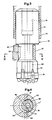
- Fig. 1 discloses a schematic, partly sectioned, side view of a drill tool according to the invention.
- Fig. 2 discloses a section along II-II in Fig. 1.
- Fig. 3 discloses a partly sectioned side view of an alternative embodiment of a drill tool according to the invention; and
- Fig. 4 discloses a section along IV-IV in Fig. 3.
- The device of Figs. 1 and 2 for earth drilling comprises an eccentric drill tool having a
guide body 10, aneccentric reamer 11 and acentric pilot bit 12. As is indicated by the threaded boring 13 theguide body 10 can be connected to a top hammer equipment (not shown). - The
upper portion 14 of theguide body 10 is surrounded by the lower end of acasing tube 15, that is driven down together with the drill tool during drilling operation. - The
reamer 11 is carried on anintermediate portion 16 of theguide body 10, saidportion 16 having a reduced diameter and thereamer 11 being rotatable a limited angle relative saidintermediate portion 16. As can be seen from Figs. 1 and 2 theintermediate portion 16 has itscentre axis 17 located eccentrically with respect to thecentre axis 18 of theguide body 10. Further the circumferential surface of thereamer 11 has a centre ofrotation 19 that is located further eccentrically with respect to thecentre axis 18 of theguide body 10, i e the wall thickness of thereamer 11 varies along its circumference. This structural design means that the radius of action for thereamer 11 reaches outside of thecasing tube 15 as shown in Figs. 1 and 2. If the reamer is rotated somewhat more than 180° clockwise from the position of Figs. 1 and 2, its external contour will fall within the internal contour of thecasing tube 15. This means that the whole eccentric drill tool can be pulled up through thecasing tube 15. - In Figs. 1 and 2 the
reamer 11 is disclosed in an active position, the drill tool being rotated in the direction of thearrow 20 in Fig. 2. By rotation in direction of the arrow 20 a drivingtongue 21 on theintermediate portion 16 will abut against ashoulder 22 of thereamer 11, saidshoulder 22 being created through arecess 23 in thereamer 11. At the opposite end of therecess 23 there is acorresponding shoulder 24. - In a conventional way the device is provided with a channel, preferably centrally located and with an axial extension. Flush medium is supplied to the front end of the drill tool through said channel.
- In order to remove flush medium and cuttings from the front part of the drill tool the device is provided with suitable means, e g grooves arranged in the envelope surface of the upper part of the
guide body 10. - The means to supply flush medium and remove flush medium and cuttings are not shown in the enclosed Figures, as these means do not constitute essential parts of the present invention.
- The above described device works in the following way.
- When the drill tool is rotated in the direction of the
arrow 20 in Fig. 2 thetongue 21 will contact theshoulder 22 and consequently thereamer 11 will be driven in the direction of rotation. The hole that is created in this way by the eccentric drill tool has, as can be seen from Fig. 1, a sufficient large diameter to drive down thecasing tube 15 at the same speed as the drilling rate of the drill tool. - Drilling with the above described equipment is done by a percussive/rotary drilling. Through the design of the
driving tongue 21 and theadherent shoulders tongue 21 transfers only rotary motion to theshoulder 22. This means that the length of life for theguide body 10 and the reamer increases. - In the device according to the invention the shock wave is thus transferred to the pilot bit substantially only via the
guide body 10. This means that the eccentric drill tool according to the present application is not especially sensitive to an increase in the working pressure of the compressed air. This is an important difference compared to the drill tool according to SE- B- 411139 (& FR-A-2388981) that is very sensitive to an increase of the working pressure due to the fact that the blasting of the inclined shoulders is accentuated. - The characteristic that the device according to the present invention is rather unsensitive to an increase of the working pressure has an extremely great importance in practice. In the fields it is not uncommon that the working pressure is not adapted to the recommendations of the manufacturer.
- As is indicated in Fig. 1 the
pilot bit 12 is connected to theguide body 10 via a threadedplug 25 that is received in a threaded boring in thepilot bit 12. This structural design allows that both thepilot bit 12 and thereamer 11 can be exchanged while theguide body 10 is maintained. This is advantageous since it is in average calculated that two pilot bits and four reamers are worn out before the guide body is consumed. In the equipment according to the above-mentioned SE, B, 411139 the pilot bit and the guide body are integral. This means that the length of life for the guide body cannot be fully exploited, at least not without grinding of the pilot bit. - By connecting the
pilot bit 12 to theguide body 10 via a threadedplug 25 it is in principle possible to use a drill bit of standard type as a pilot bit. - When drilling has been carried out to the required level the
guide body 10 and thepilot bit 12 are rotated in the direction of thearrow 26. Thereamer 11 is not following this rotation but is kept in place through the engagement in the soil layer until thetongue 21 contacts theshoulder 24. When this position is achieved thereamer 11 will be inside of the prolongation of thecasing tube 15 and consequently the whole eccentric drill tool can be pulled up through thetube 15. - The embodiment disclosed in Figs. 3 and 4 differs from the above described in that the driving tongue 21ʹ is arranged on the reamer 11ʹ. A further difference is that the intermediate portion 16ʹ has a recess 23ʹ provided with shoulders 22ʹ and 24ʹ respectively.
- Concerning the working of the embodiment of Figs. 3 and 4 it is fully correspondent to the working of the above described embodiment and therefore reference is made to the relevant parts of said above description.
- Common for the two embodiments is that the
driving tongue 21; 21ʹ has an extension in the longitudinal direction of the eccentric drill tool, said extension corresponds to a major extent of the height of thereamer 11; 11ʹ, at least half of the height of thereamer 11; 11ʹ. This guarantees that the driving is carried out without risk for jamming/clamping and fatigue of material resp in the cooperating parts (tongue - shoulder). - When mounting and dismounting the
reamer 11; 11ʹ thepilot bit 12 is unscrewed from theplug 25 and then thereamer 11; 11ʹ is pushed on or off theintermediate portion 16; 16ʹ of theguide body 10. To achieve this the upper end of thereamer 11 or the lower end of the intermediate portion 16ʹ must be provided with a groove (not shown) that corresponds to thetongue 21; 21ʹ. - The disclosed embodiments refer to top hammer drilling. However, eccentric drill tools are also used in down-the-hole hammer drilling. The direction of rotation is opposite for these types of drilling. An extremely great advantage for the present invention is that the structural design of the reamer is alike regardless if it is used for top hammer drilling or down-the-hole hammer drilling.
- The invention is not in any way restricted to the above described embodiments but can be varied within the scope of the appending claims.
Claims (13)
7. Drill tool according to claim 5, characterized in that the recess (23ʹ) in the intermediate portion (16ʹ) holds an angle of more than 180° in respect to the centre of rotation (17) for the inner limit surface of the reamer (11ʹ).
Priority Applications (1)
| Application Number | Priority Date | Filing Date | Title |
|---|---|---|---|
| AT87850054T ATE61446T1 (en) | 1986-02-24 | 1987-02-16 | DRILLING TOOL. |
Applications Claiming Priority (2)
| Application Number | Priority Date | Filing Date | Title |
|---|---|---|---|
| SE8600820 | 1986-02-24 | ||
| SE8600820A SE460141B (en) | 1986-02-24 | 1986-02-24 | DRILLING TOOL FOR ROTATION AND / OR SHIPPING DRILLING INCLUDING AN Eccentric Rifle AND RIDER INCLUDED IN SUCH A DRILLING TOOL |
Publications (3)
| Publication Number | Publication Date |
|---|---|
| EP0235105A2 EP0235105A2 (en) | 1987-09-02 |
| EP0235105A3 EP0235105A3 (en) | 1988-12-07 |
| EP0235105B1 true EP0235105B1 (en) | 1991-03-06 |
Family
ID=20363569
Family Applications (1)
| Application Number | Title | Priority Date | Filing Date |
|---|---|---|---|
| EP87850054A Expired - Lifetime EP0235105B1 (en) | 1986-02-24 | 1987-02-16 | Drill tool |
Country Status (9)
| Country | Link |
|---|---|
| US (1) | US4770259A (en) |
| EP (1) | EP0235105B1 (en) |
| AT (1) | ATE61446T1 (en) |
| AU (1) | AU605756B2 (en) |
| CA (1) | CA1295605C (en) |
| DE (1) | DE3768293D1 (en) |
| FI (1) | FI86760C (en) |
| IE (1) | IE59491B1 (en) |
| SE (1) | SE460141B (en) |
Cited By (7)
| Publication number | Priority date | Publication date | Assignee | Title |
|---|---|---|---|---|
| US7650944B1 (en) | 2003-07-11 | 2010-01-26 | Weatherford/Lamb, Inc. | Vessel for well intervention |
| US7712523B2 (en) | 2000-04-17 | 2010-05-11 | Weatherford/Lamb, Inc. | Top drive casing system |
| US7730965B2 (en) | 2002-12-13 | 2010-06-08 | Weatherford/Lamb, Inc. | Retractable joint and cementing shoe for use in completing a wellbore |
| US7857052B2 (en) | 2006-05-12 | 2010-12-28 | Weatherford/Lamb, Inc. | Stage cementing methods used in casing while drilling |
| US7938201B2 (en) | 2002-12-13 | 2011-05-10 | Weatherford/Lamb, Inc. | Deep water drilling with casing |
| USRE42877E1 (en) | 2003-02-07 | 2011-11-01 | Weatherford/Lamb, Inc. | Methods and apparatus for wellbore construction and completion |
| US8276689B2 (en) | 2006-05-22 | 2012-10-02 | Weatherford/Lamb, Inc. | Methods and apparatus for drilling with casing |
Families Citing this family (23)
| Publication number | Priority date | Publication date | Assignee | Title |
|---|---|---|---|---|
| EP0358786A1 (en) * | 1988-09-13 | 1990-03-21 | Ing. G. Klemm Bohrtechnik GmbH | Superimposing drilling device |
| SE8900473L (en) * | 1989-02-13 | 1990-08-14 | Sandvik Ab | DRILL BIT |
| SE501988C2 (en) * | 1989-04-05 | 1995-07-10 | Uniroc Ab | Drilling tools for drilling in soil and covered rock |
| JPH04500105A (en) * | 1989-05-19 | 1992-01-09 | フセソユズニ ナウチノ―イススレドバテルスキ インスティテュト メトディキ イ テフニキ ラズベドキ,ナウチノ―プロイズボドストベンノエ オビエディネニエ“ゲオテフニカ” | drilling tools |
| AU633319B2 (en) * | 1989-06-09 | 1993-01-28 | Sandvik Ab | Drill tool |
| US4962822A (en) * | 1989-12-15 | 1990-10-16 | Numa Tool Company | Downhole drill bit and bit coupling |
| SE467632B (en) * | 1990-01-17 | 1992-08-17 | Uniroc Ab | DRILLING TOOL FOR BATTING AND ROTATING DRILLING WHILE CONDUCTING A FEEDING PIPE |
| US5009271A (en) * | 1990-07-16 | 1991-04-23 | Milan Maric | Drill assembly |
| US5186265A (en) * | 1991-08-22 | 1993-02-16 | Atlantic Richfield Company | Retrievable bit and eccentric reamer assembly |
| US5992548A (en) * | 1995-08-15 | 1999-11-30 | Diamond Products International, Inc. | Bi-center bit with oppositely disposed cutting surfaces |
| US5787999A (en) * | 1996-07-01 | 1998-08-04 | Holte; Ardis L. | Drill bit with set of underreamer arms |
| US6213226B1 (en) | 1997-12-04 | 2001-04-10 | Halliburton Energy Services, Inc. | Directional drilling assembly and method |
| US6325162B1 (en) | 1997-12-04 | 2001-12-04 | Halliburton Energy Services, Inc. | Bit connector |
| US6920944B2 (en) * | 2000-06-27 | 2005-07-26 | Halliburton Energy Services, Inc. | Apparatus and method for drilling and reaming a borehole |
| US6112835A (en) * | 1998-07-23 | 2000-09-05 | Sandvik Ab | Drilling apparatus having a radially displaceable reamer |
| SE515518C2 (en) * | 1998-09-28 | 2001-08-20 | Uniroc Ab | String drill string thread for striking rock drilling |
| US7311148B2 (en) | 1999-02-25 | 2007-12-25 | Weatherford/Lamb, Inc. | Methods and apparatus for wellbore construction and completion |
| US7334650B2 (en) | 2000-04-13 | 2008-02-26 | Weatherford/Lamb, Inc. | Apparatus and methods for drilling a wellbore using casing |
| SE524156C2 (en) * | 2002-05-31 | 2004-07-06 | Atlas Copco Secoroc Ab | Fuse arrangement at drill bit for raisers |
| SE0400929L (en) | 2004-04-07 | 2005-09-27 | Atlas Copco Rotex Ab Oy | Device for lowering drilling tools with pilot drill bit, pusher and guide body |
| IT1404943B1 (en) | 2010-06-14 | 2013-12-09 | Soilmec Spa | DEVICE AND METHOD OF PERFORATION IN CONSTITUTION OF SOIL. |
| JP6507012B2 (en) * | 2015-04-01 | 2019-04-24 | 孝幸 千葉 | Double pipe drilling tool |
| AT15492U1 (en) * | 2016-05-20 | 2017-10-15 | Dywidag-Systems Int Gmbh | Method for impact or rotary impact drilling of holes and simultaneous profiling of borehole walls in earth, soil or rock material |
Family Cites Families (11)
| Publication number | Priority date | Publication date | Assignee | Title |
|---|---|---|---|---|
| FR1357144A (en) * | 1963-02-28 | 1964-04-03 | Skanska Cementgjuteriet Ab | Advanced training in eccentric trephine drills |
| US3416616A (en) * | 1967-03-01 | 1968-12-17 | Skanska Cementgjuteriet Ab | Deep drills with eccentric bits |
| SE325005B (en) * | 1968-10-16 | 1970-06-22 | Atlas Copco Ab | |
| SE346354B (en) * | 1970-11-27 | 1972-07-03 | Atlas Copco Ab | |
| BE795205A (en) * | 1972-02-10 | 1973-05-29 | Atlas Copco Ab | METHOD AND APPARATUS FOR ROTARY DRILLING |
| US3870114A (en) * | 1973-07-23 | 1975-03-11 | Stabilator Ab | Drilling apparatus especially for ground drilling |
| US3960222A (en) * | 1974-08-29 | 1976-06-01 | Kennametal Inc. | Tool for cutting groove in hole |
| SE411139B (en) * | 1977-04-29 | 1979-12-03 | Sandvik Ab | DRILLING DEVICE |
| SE421551B (en) * | 1980-03-26 | 1982-01-04 | Sandvik Ab | DRILLING TOOL FOR ROTATION AND / OR DRILLING |
| GB2132252B (en) * | 1982-10-25 | 1985-12-18 | Tone Boring Co | An air hammer drill device |
| SE454196C (en) * | 1983-09-23 | 1991-10-24 | Jan Persson | EARTH AND MOUNTAIN DRILLING DEVICE CONCERNING BORING AND LINING OF THE DRILL |
-
1986
- 1986-02-24 SE SE8600820A patent/SE460141B/en not_active Application Discontinuation
-
1987
- 1987-02-16 EP EP87850054A patent/EP0235105B1/en not_active Expired - Lifetime
- 1987-02-16 AT AT87850054T patent/ATE61446T1/en not_active IP Right Cessation
- 1987-02-16 DE DE8787850054T patent/DE3768293D1/en not_active Expired - Lifetime
- 1987-02-19 AU AU69073/87A patent/AU605756B2/en not_active Expired
- 1987-02-20 CA CA000530165A patent/CA1295605C/en not_active Expired - Lifetime
- 1987-02-23 IE IE45587A patent/IE59491B1/en not_active IP Right Cessation
- 1987-02-24 FI FI870786A patent/FI86760C/en not_active IP Right Cessation
- 1987-02-24 US US07/017,596 patent/US4770259A/en not_active Expired - Lifetime
Cited By (7)
| Publication number | Priority date | Publication date | Assignee | Title |
|---|---|---|---|---|
| US7712523B2 (en) | 2000-04-17 | 2010-05-11 | Weatherford/Lamb, Inc. | Top drive casing system |
| US7730965B2 (en) | 2002-12-13 | 2010-06-08 | Weatherford/Lamb, Inc. | Retractable joint and cementing shoe for use in completing a wellbore |
| US7938201B2 (en) | 2002-12-13 | 2011-05-10 | Weatherford/Lamb, Inc. | Deep water drilling with casing |
| USRE42877E1 (en) | 2003-02-07 | 2011-11-01 | Weatherford/Lamb, Inc. | Methods and apparatus for wellbore construction and completion |
| US7650944B1 (en) | 2003-07-11 | 2010-01-26 | Weatherford/Lamb, Inc. | Vessel for well intervention |
| US7857052B2 (en) | 2006-05-12 | 2010-12-28 | Weatherford/Lamb, Inc. | Stage cementing methods used in casing while drilling |
| US8276689B2 (en) | 2006-05-22 | 2012-10-02 | Weatherford/Lamb, Inc. | Methods and apparatus for drilling with casing |
Also Published As
| Publication number | Publication date |
|---|---|
| AU605756B2 (en) | 1991-01-24 |
| IE870455L (en) | 1987-08-24 |
| SE460141B (en) | 1989-09-11 |
| CA1295605C (en) | 1992-02-11 |
| IE59491B1 (en) | 1994-03-09 |
| DE3768293D1 (en) | 1991-04-11 |
| FI86760C (en) | 1992-10-12 |
| FI870786A (en) | 1987-08-25 |
| EP0235105A3 (en) | 1988-12-07 |
| SE8600820D0 (en) | 1986-02-24 |
| AU6907387A (en) | 1987-08-27 |
| SE8600820L (en) | 1987-08-25 |
| ATE61446T1 (en) | 1991-03-15 |
| US4770259A (en) | 1988-09-13 |
| EP0235105A2 (en) | 1987-09-02 |
| FI870786A0 (en) | 1987-02-24 |
| FI86760B (en) | 1992-06-30 |
Similar Documents
| Publication | Publication Date | Title |
|---|---|---|
| EP0235105B1 (en) | Drill tool | |
| US4408669A (en) | Means for drilling | |
| US5052503A (en) | Eccentric drilling tool | |
| EP0052978B1 (en) | A cutting tool | |
| US7641002B2 (en) | Drill bit | |
| US7207402B2 (en) | Percussion drill bit and a regrindable cemented carbide button therefor | |
| CA2255179C (en) | Drilling motor drill bit reaming stabilizer | |
| US4903787A (en) | Rock drill | |
| US4433739A (en) | Mining drill | |
| EP0515538B1 (en) | A down-the-hole drill tool for drilling in advance of a casing tube | |
| US4091884A (en) | Rotary air percussion bit | |
| CA1335812C (en) | Excavating tooth for an earth auger | |
| US3519092A (en) | Percussion bit | |
| US6021856A (en) | Bit retention system | |
| GB2314358A (en) | Cutting bed impeller | |
| US6435288B1 (en) | Rock drill bit | |
| US4069880A (en) | Excavation tool | |
| EP0198809A2 (en) | Rock drilling device and a drill stem for said device | |
| US4488609A (en) | Mining drill | |
| US6112835A (en) | Drilling apparatus having a radially displaceable reamer | |
| CA2322693C (en) | An arrangement for drilling slots | |
| EP0276161A2 (en) | Self-adjusting bit basket | |
| EP0402337A2 (en) | Drill tool | |
| RU1775543C (en) | Reamer | |
| JP2785421B2 (en) | Drilling tool |
Legal Events
| Date | Code | Title | Description |
|---|---|---|---|
| PUAI | Public reference made under article 153(3) epc to a published international application that has entered the european phase |
Free format text: ORIGINAL CODE: 0009012 |
|
| AK | Designated contracting states |
Kind code of ref document: A2 Designated state(s): AT BE DE GB SE |
|
| PUAL | Search report despatched |
Free format text: ORIGINAL CODE: 0009013 |
|
| AK | Designated contracting states |
Kind code of ref document: A3 Designated state(s): AT BE DE GB SE |
|
| 17P | Request for examination filed |
Effective date: 19890111 |
|
| 17Q | First examination report despatched |
Effective date: 19890830 |
|
| GRAA | (expected) grant |
Free format text: ORIGINAL CODE: 0009210 |
|
| AK | Designated contracting states |
Kind code of ref document: B1 Designated state(s): AT BE DE GB SE |
|
| REF | Corresponds to: |
Ref document number: 61446 Country of ref document: AT Date of ref document: 19910315 Kind code of ref document: T |
|
| REF | Corresponds to: |
Ref document number: 3768293 Country of ref document: DE Date of ref document: 19910411 |
|
| PLBE | No opposition filed within time limit |
Free format text: ORIGINAL CODE: 0009261 |
|
| STAA | Information on the status of an ep patent application or granted ep patent |
Free format text: STATUS: NO OPPOSITION FILED WITHIN TIME LIMIT |
|
| 26N | No opposition filed | ||
| EAL | Se: european patent in force in sweden |
Ref document number: 87850054.5 |
|
| REG | Reference to a national code |
Ref country code: GB Ref legal event code: IF02 |
|
| PGFP | Annual fee paid to national office [announced via postgrant information from national office to epo] |
Ref country code: SE Payment date: 20060207 Year of fee payment: 20 |
|
| PGFP | Annual fee paid to national office [announced via postgrant information from national office to epo] |
Ref country code: DE Payment date: 20060209 Year of fee payment: 20 |
|
| PGFP | Annual fee paid to national office [announced via postgrant information from national office to epo] |
Ref country code: AT Payment date: 20060213 Year of fee payment: 20 |
|
| PGFP | Annual fee paid to national office [announced via postgrant information from national office to epo] |
Ref country code: GB Payment date: 20060215 Year of fee payment: 20 |
|
| PGFP | Annual fee paid to national office [announced via postgrant information from national office to epo] |
Ref country code: BE Payment date: 20060410 Year of fee payment: 20 |
|
| PG25 | Lapsed in a contracting state [announced via postgrant information from national office to epo] |
Ref country code: GB Free format text: LAPSE BECAUSE OF EXPIRATION OF PROTECTION Effective date: 20070215 |
|
| REG | Reference to a national code |
Ref country code: GB Ref legal event code: PE20 |
|
| EUG | Se: european patent has lapsed | ||
| BE20 | Be: patent expired |
Owner name: *SANTRADE LTD Effective date: 20070216 |