EP0235918A2 - Method of forming a one-piece can body having an end reinforcing radius and/or stacking bead - Google Patents
Method of forming a one-piece can body having an end reinforcing radius and/or stacking bead Download PDFInfo
- Publication number
- EP0235918A2 EP0235918A2 EP87300672A EP87300672A EP0235918A2 EP 0235918 A2 EP0235918 A2 EP 0235918A2 EP 87300672 A EP87300672 A EP 87300672A EP 87300672 A EP87300672 A EP 87300672A EP 0235918 A2 EP0235918 A2 EP 0235918A2
- Authority
- EP
- European Patent Office
- Prior art keywords
- annular
- radius
- central
- frusto
- forces
- Prior art date
- Legal status (The legal status is an assumption and is not a legal conclusion. Google has not performed a legal analysis and makes no representation as to the accuracy of the status listed.)
- Granted
Links
- 239000011324 bead Substances 0.000 title claims abstract description 42
- 238000000034 method Methods 0.000 title claims description 15
- 230000003014 reinforcing effect Effects 0.000 title abstract description 15
- 230000009466 transformation Effects 0.000 claims 3
- 230000002093 peripheral effect Effects 0.000 description 17
- 239000002184 metal Substances 0.000 description 11
- 239000013256 coordination polymer Substances 0.000 description 7
- 238000002407 reforming Methods 0.000 description 7
- 230000009471 action Effects 0.000 description 4
- 125000006850 spacer group Chemical group 0.000 description 4
- 230000015572 biosynthetic process Effects 0.000 description 3
- 230000006835 compression Effects 0.000 description 3
- 238000007906 compression Methods 0.000 description 3
- 230000004048 modification Effects 0.000 description 3
- 238000012986 modification Methods 0.000 description 3
- 230000000750 progressive effect Effects 0.000 description 3
- IJGRMHOSHXDMSA-UHFFFAOYSA-N Atomic nitrogen Chemical compound N#N IJGRMHOSHXDMSA-UHFFFAOYSA-N 0.000 description 2
- 239000000463 material Substances 0.000 description 2
- 230000001105 regulatory effect Effects 0.000 description 2
- 238000005482 strain hardening Methods 0.000 description 2
- 241000239290 Araneae Species 0.000 description 1
- 230000004323 axial length Effects 0.000 description 1
- 230000008859 change Effects 0.000 description 1
- 239000011248 coating agent Substances 0.000 description 1
- 238000000576 coating method Methods 0.000 description 1
- 230000009133 cooperative interaction Effects 0.000 description 1
- 238000005336 cracking Methods 0.000 description 1
- 210000003298 dental enamel Anatomy 0.000 description 1
- 239000012530 fluid Substances 0.000 description 1
- 239000004922 lacquer Substances 0.000 description 1
- 229910052757 nitrogen Inorganic materials 0.000 description 1
- 230000002787 reinforcement Effects 0.000 description 1
- 239000007787 solid Substances 0.000 description 1
- 230000007704 transition Effects 0.000 description 1
- 239000002699 waste material Substances 0.000 description 1
Images


Classifications
-
- B—PERFORMING OPERATIONS; TRANSPORTING
- B21—MECHANICAL METAL-WORKING WITHOUT ESSENTIALLY REMOVING MATERIAL; PUNCHING METAL
- B21D—WORKING OR PROCESSING OF SHEET METAL OR METAL TUBES, RODS OR PROFILES WITHOUT ESSENTIALLY REMOVING MATERIAL; PUNCHING METAL
- B21D51/00—Making hollow objects
- B21D51/16—Making hollow objects characterised by the use of the objects
- B21D51/38—Making inlet or outlet arrangements of cans, tins, baths, bottles, or other vessels; Making can ends; Making closures
- B21D51/44—Making closures, e.g. caps
-
- B—PERFORMING OPERATIONS; TRANSPORTING
- B21—MECHANICAL METAL-WORKING WITHOUT ESSENTIALLY REMOVING MATERIAL; PUNCHING METAL
- B21D—WORKING OR PROCESSING OF SHEET METAL OR METAL TUBES, RODS OR PROFILES WITHOUT ESSENTIALLY REMOVING MATERIAL; PUNCHING METAL
- B21D22/00—Shaping without cutting, by stamping, spinning, or deep-drawing
- B21D22/20—Deep-drawing
- B21D22/30—Deep-drawing to finish articles formed by deep-drawing
-
- B—PERFORMING OPERATIONS; TRANSPORTING
- B21—MECHANICAL METAL-WORKING WITHOUT ESSENTIALLY REMOVING MATERIAL; PUNCHING METAL
- B21D—WORKING OR PROCESSING OF SHEET METAL OR METAL TUBES, RODS OR PROFILES WITHOUT ESSENTIALLY REMOVING MATERIAL; PUNCHING METAL
- B21D51/00—Making hollow objects
- B21D51/16—Making hollow objects characterised by the use of the objects
- B21D51/26—Making hollow objects characterised by the use of the objects cans or tins; Closing same in a permanent manner
-
- B—PERFORMING OPERATIONS; TRANSPORTING
- B65—CONVEYING; PACKING; STORING; HANDLING THIN OR FILAMENTARY MATERIAL
- B65D—CONTAINERS FOR STORAGE OR TRANSPORT OF ARTICLES OR MATERIALS, e.g. BAGS, BARRELS, BOTTLES, BOXES, CANS, CARTONS, CRATES, DRUMS, JARS, TANKS, HOPPERS, FORWARDING CONTAINERS; ACCESSORIES, CLOSURES, OR FITTINGS THEREFOR; PACKAGING ELEMENTS; PACKAGES
- B65D1/00—Containers having bodies formed in one piece, e.g. by casting metallic material, by moulding plastics, by blowing vitreous material, by throwing ceramic material, by moulding pulped fibrous material, by deep-drawing operations performed on sheet material
- B65D1/12—Cans, casks, barrels, or drums
- B65D1/14—Cans, casks, barrels, or drums characterised by shape
- B65D1/16—Cans, casks, barrels, or drums characterised by shape of curved cross-section, e.g. cylindrical
- B65D1/165—Cylindrical cans
Definitions
- the present invention is directed to a method of and apparatus for forming a one-piece can body having a bottom reinforcing bead and a stacking bead.
- a one-piece can body having a reinforced pressure-resistant can bottom is formed by first forming a generally cup-shaped blank defined by a generally cylindrical body, a radius portion and an end, exerting first forces against the cup-shaped blank in a first direction to form the end into a concavely outwardly opening end defined by a central end panel, a frusto-conical wall and an annular inwardly opening channel merging with the cylindrical body, and exerting second forces against the annular channel in a second direction opposite the first direction while gripping the central end panel to reform either or both the frusto-conical wall and a part of the annular channel to selectively form one or both of an inwardly projecting outwardly opening annular bead and an outwardly projecting inwardly opening annular bead defining respective reinforcing and stacking beads, and the first and second directions defining a single reciprocal opposing path of force exertion by the first and second forces.
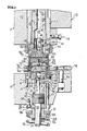
- Fig. 1 of the drawings illustrates a portion of a conventional multi-die double action press which is generally designated by the reference numeral 10.
- the press 10 includes a punch 11 and a die 12.
- the die 12 is a stationary portion of the frame (not shown) of the press 10 while the punch 11 is reciprocated in a conventional manner, as by eccentrics or cams between a fully closed or bottom dead center position (Fig. 1) and a fully opened position (not shown).
- the punch 11 has been moved through its forming stroke during which a flat or shallow cup-shaped blank has been drawn and wall ironed into a can body B , as disclosed in the latter patent.
- the die 12 includes a generally cylindrical upwardly opening recess 13 housing a draw die base 14 which is secured to the assembly 12 by a plurality of hex screws 15 received in a plurality of counter-bored bores 16 and threaded in threaded bores 17 of the assembly 12.
- a bottom wall (unnumbered) of the draw die base includes an axial bore 18 in which is reciprocally moved an upper portion 20 of a knock-out lift ring rod 21.
- the bottom wall (unnumbered) of the draw die base 14 also includes four counterbores 22 of which only one is illustrated in Fig. 1, and a hex screw 23 is received in each counterbore 22 and is threaded in a threaded bore 24 of an indent ring 25 seated within a shallow upwardly opening circular recess 29 of the draw die base 14.
- the indent ring 25 and a convex face 26 thereof clamp the end panel CP in cooperation with a concave surface 36 of a reform pad 35 of the punch 11, as will be described more fully hereinafter.
- the indent ring 25 additionally includes a generally cylindrical outer surface 27, and the surfaces 26, 27 are bridged by means 40 for creating unrestrained tensioning of center panel CP of the can or blank B during the formation of a somewhat angulated radius R (Fig. 7) defined by a pair of shoulders or radius portions Rb and Rc spanned by an annular generally flat angled wall portion Rt (Fig. 7).
- the tensioning means 40 includes a pair of annular shoulders 41, 42 between which is an outwardly opening annular groove 43. The radii of the shoulders 41, 42 are respectively .030" and .065", while the radius of the annular groove 43 is .010".
- the distance of the axis for the radius of the shoulder 42 from the axial terminal end face 26 of the indent ring 25 is generally .015" and the distance of the axis of the radius 41 from the axis of the indent ring 25 is approximately 0.976" - 0.977".
- a lower portion (unnumbered) of the indent ring 25 is traversed by a diametric slot 28 (Fig. 1) which transforms a lower end portion of the indent ring 25 into a pair of legs 30, 31.
- the diametric slot 28 accommodates reciprocal movement of a hub 105 forming a part of a diametric spider (not shown) of a lift ring 60.
- Each of the legs 30, 31 of the indent ring 25 includes a vertical slot 32, 33, respectively, functioning as a vertical limit for reciprocal motion of the lift ring 60.
- the base 14 also includes six equally circumferentially spaced bores 34 and six equally circumferentially spaced blind bores 45.
- Each of the boxes 34 receives a reduced end portion 46 of a lift pin 47 while each of the blind bores 45 houses a compression spring 48.
- the compression springs 48 bear against the undersurface of a draw die 70 which cooperates in a conventional manner with a cutting punch 75 of the punch 11 and a cut edge or annular blanking die 76 carried by a die holder 78 secured in a conventional manner to the bolster block assembly 12 by a plurality of hex socket screws and nuts 81.
- a draw die 70 which cooperates in a conventional manner with a cutting punch 75 of the punch 11 and a cut edge or annular blanking die 76 carried by a die holder 78 secured in a conventional manner to the bolster block assembly 12 by a plurality of hex socket screws and nuts 81.
- the lift ring 60 includes an outer peripheral cylindrical surface 61 and an inner peripheral cylindrical surface 62.
- a terminal peripheral end face 64 bridges the peripheral surfaces 61 and 62.
- the terminal peripheral end face 64 includes a shallow upwardly opening convex recess 65, a relatively deep axially upwardly opening annular channel 69, an inboard annular axial face or surface 66 and an outboard annular axial face or surface 67.
- the surface 66 is radially longer than and slightly above (0.030") the surface 67.
- the collective surfaces 65 through 67 provide guidance to inward metal flow of a peripheral portion or cylindrical wall PP of the can body B during the downward or forming stroke of the press and a clamping or gripping action during the upward or reforming stroke, as will be described more fully hereinafter.
- the bumper retainer plate 92 is secured to the bolster block assembly 12 by a plurality of hex socket screws 96 received in counterbores 97 of the bumper retainer plate 92 and threaded in threaded bores 98 of the bolster block assembly 12.
- the bolster block assembly 12 also includes a threaded bore 101 into which is threaded an enlarged threaded portion 102 of a lift ring knock-out bumper 103 having an axial bore 104 within which reciprocates the knock-out lift ring rod 21.
- the punch 11 includes a conventional blank punch slide assembly 110 which has mounted thereto a conventional cutting punch holder 111 by means of a blank ram attachment 112 (only on illustrated) and an associated set screw 113.
- the cutting punch 75 is secured in a conventional manner, including a cutting punch holder clamping nut 114, to lower end portion of the cutting punch holder 111.
- An inner piston or draw punch rod 120 is mounted for reciprocal movement within the cutting punch holder 111 and includes a bore 121, a counterbore 122 and an internally threaded end portion 123.
- the internally threaded end portion 123 is threaded to a threaded portion 82 of a stem 83 of a draw punch 80.
- the draw punch 80 includes an axial bore 84 and a counterbore 85 defined by a peripheral skirt or annular forming member 86 of the draw punch 80.
- the counterbore 85 is defined in part by an inner cylindrical peripheral surface 87 which is in intimate sliding contact with a like outer peripheral cylindrical surface 37 (Fig. 2) of the reform pad 35.
- the cylindrical surface 37 and the axial end face 36 of the reform pad 35 are bridged by means 38 in the form of an angled annular surface setting-off an obtuse angle of approximately 120° with the terminal end face 36.
- a like obtuse angle is set-off between the peripheral surface 37 and the angled annular surface 38.
- the means 38 functions to prevent a coating upon the blank B , such as lacquer or enamel, from cracking or being wiped-off and, thus, prevents metal exposure of the eventually formed inner surface of the can body B during the forming and reforming operation.
- the annular surface 38 cooperatively functions with a frusto-conical surface 88 of the draw punch 80 to define therewith and therebetween means for forming an annular downwardly opening and diverging chamber 130 into which the formed radius R (Fig. 7) can be freely reformed without guidance or restraint (See Figs. 8 and 9) during the upward stroke or movement of the lift ring 60 to eventually form an annular reinforcing countersink radius Rr (Fig. 9).
- the frusto-conical surface 88 merges with a pair of convex radii 136, 137 bridged by a generally flat annular surface 138.
- the curvature of the radii/surfaces 136 through 138 corresponds to the curvature of the surface 65 of the groove 64 which together therewith provides added guidance to the inward metal flow during the downward or forming stroke when the can body B is formed to its final formed (though not reformed) configuration (Fig. 7).
- a hex screw 140 (Fig. 1) is threaded into a threaded bore (unnumbered) of a draw punch piston 141 having a blind bore 142, a plurality of seals 143 and a peripheral flange 144 which can bottom against an annular axial end face 145 of the draw punch stem 83.
- the counterbore 122 is connected through the bore 121 to a supply of fluid pressure, such as a nitrogen cylinder and an associated air amplifier with appropriate valving and controls, which is simply designated by the headed arrow P 1.
- the inner piston or draw punch rod 120 is likewise urged downwardly by fluidic pressure suitably regulated from the same or a different source as the pressure source P 1, and the pressure applied to the draw punch rod 120 is generally designated by the reference character P 2, although pressures P 1, P 2 can be equal.
- the pressure P 1 can be, for example as low as 600 psi and at 1000 psi, the pressure on the piston 141 is approximately 1060 psi.
- the pressure is preferably higher, particularly the pressure P 2 exerted in a downward direction upon the draw punch rod 120 because the latter pressure is transferred during the downward or forming stroke from the rod 120 through the draw punch 80, the lift ring 60 and the lift pins 47 to unseat the lift pin disc 91 and the lift pin spacer 94 and, therefore, load the springs 93, 95 which upon the reform or return stroke of the rod 120 provide the mechanical force to lift the rods 47 and the lift ring 60 upwardly to reform the can body B from the position shown in Fig. 7 to that shown in Fig. 9 under a second force greater than the first pressure force P 2.
- the blank punch slide assembly 110 (Fig. 1) of the punch 11 has already been fully retracted upwardly to its open position and thereafter moved downwardly to the position shown in Fig. 2.
- the can body B of Fig. 2 is formed during the latter-noted downward movement from either a flat metallic blank or a shallow cup-shaped blank as the blank is drawn through the set of dies corresponding to the dies 52 of U.S. Patent No. 3,908,429.
- the draw die 70 of the cutting punch 75 trims the blank and toward the bottom of the punch stroke the can body B is drawn generally to its desired axial length.
- the sequential steps depicted in Figs. 2 through 9 depict forming and reforming the can bottom approaching the end of the forming stroke.
- the means for providing the pressures P 1 and/or P 2 are activated and the flange 144 of the draw punch 141 is bottomed against the annular face 145 (Fig. 1) of the stem 83 of the draw punch 80.
- the respective surfaces 138, 36 are initially spaced from the opposing surfaces 65, 26 of the respective lift ring 60 and indent ring 25, although these surfaces progressively move closer toward each other, as is readily apparent by comparing Figs. 2, 3 and 4.
- Upper end faces of the lift pin disc 91 and the lift pin spacer 94 are, of course, in abutment with an undersurface (unnumbered) of the bumper retainer plate 92 (Fig. 1) at this time.
- the cylindrical wall PP of the can body B is drawn radially inwardly between the surfaces 138, 65 and 66 resulting in the formation of a shallow upwardly opening annular channel SC defined by a radius R 1, an annular wall AW and another radius R 2.
- the radius R 2 merges with a frusto-conical wall FW which in turn merges with the central panel CP (Fig. 6).
- the material of the cylindrical wall PP continues to be drawn between the surfaces 136 through 138 on the one hand and 65 through 67 on the other until the frusto-conical wall FW of Fig. 6 is generally contoured into a pair of frusto-conical walls FW 1, FW 2 bridged by the radius Rb (Fig. 7).
- the surface 65 and the surfaces 136 through 138 function to guide the inward metal flow of the cylindrical wall PP as it is progressively formed toward the eventually angulated radius R of Fig. 7. From the position of the lift ring 60 shown in Fig. 6 to that shown in Fig.
- the draw punch 80 which moved forcibly downwardly by the pressure P 2 is effective for exerting forces sufficient to transform the peripheral edge portion of the can body B to the configuration of the formed (though not reformed) can body B of Fig. 7 in which the frusto-conical wall portion is tensioned at Rt and work hardening occurs in the material of the radius Rc .
- the reform or return stroke (Fig. 8) is initiated without any change in the position of the blank punch slide assembly 110 and the cutting punch holder 111, and without in any way reducing the clamping action against the center panel CP of the can body B between the surfaces 26, 36 of the respective indent ring 25 and the reform pad 35.
- the springer springs 93, 95 urge the lift pins 47 upwardly against the regulated decrease in the pressures P 1 and/or P 2 (Fig. 8)
- the annular wall portion AW of the can body B is also clamped or gripped between the surfaces 137, 138 of the draw punch 80 and the surface 65 of the lift ring 60.
- Figs. 7 and 8 which in practice is known as a "stacking" bead.
- the transition that occurs between Figs. 7 and 8 is illustrated by the solid lines representing the initial reforming followed by the phantom outlines and the eventual complete reformed can 150.
- the radius portion Rc of Fig. 7 is generally reversely progressively formed from the position shown in Fig. 7 to that which it eventually reaches in Fig. 9, while at the same time the radius portion Rt is deformed progressively and without restraint, guidance or confinement into the annular channel or chamber 130 until the reinforcing countersink radius Rr (Fig. 9) is fully formed.
- the distance between the surface 36 of the draw punch 80 and the surface 65 of the lift ring 60 is such as to readily accommodate and permit the metal in the area of the radius R 2 to flow into the channel 69 as the lift ring 60 progressively rises, as is again best illustrated by the progressively lowermost phantom outline position shown in Fig. 8 followed by the solid line position in this same figure, and eventually the uppermost outlying position in Fig. 8 until the final position of Fig. 9.
- the downward force or pressure on the draw punch 80 can be progressively released as the lift ring 60 moves upwardly which assures that the metal of the frusto-conical wall FW 1 moves without restraint into not only the channel 69 but also, of course, into the diverging chamber 130.
- the reformed can 150 includes the generally circular concavely outwardly opening central panel or panel portion 151, the flexible annular wall portion 152 immediately adjacent the panel radius 153, the panel radius 153, a frusto-conical peripheral inner wall 154, an annular exteriorly upwardly opening reinforcing countersink, channel radius or bead 155, a frusto-conical peripherally outer wall 156, an axially projecting radius or "stacking" bead 157, an annular end wall 158, an outermost radius 159 and a cylindrical body or wall 161.
- Figs. 12 and 13 identical reference numerals have been provided, except primed, to identify structure identical to that illustrated respectively in Figs. 7 and 9.
- the reform pad 35 ⁇ has been modified by altering the overall configuration of adjoining surfaces 170 through 172 bridging surfaces 36 ⁇ and 37 ⁇ .
- the surface 170 is of an angular configuration, similar to the surface 38 of the reform pad 35.
- the surface 172 is radially outboard of the corresponding radius 41 ⁇ of the indent ring 25 ⁇ , and as a result the annularly downwardly opening chamber 130 ⁇ abruptly narrows at the cylindrical surface 171.
- the radius R ⁇ r is "tighter" or closed, as is most readily apparent by comparing the radius Rr of Figs. 9 and 10 with the radius R ⁇ r of Fig. 13. This results in a more rigid reinforcement of the countersink radius R ⁇ r or 155 ⁇ than that provided by the reinforcing countersink radius 155. Otherwise, the stacking bead 157 ⁇ of the can 150 ⁇ is the same as the stacking bead 57 of Fig. 11.
- Figs. 14 through 22 of the drawings structurally correspond to the positions of the parts of the punch and die of Figs. 2 through 10, respectively. Accordingly, the parts of the punch and die of Figs. 14 through 22 corresponding generally identically to Figs. 2 through 10 have been identically numbered, though the same have been double primed. These parts include an identical draw punch 80 ⁇ , an identical lift ring 60 ⁇ , and an identical lift ring 25 ⁇ .
- a reform pad 35 ⁇ differs from the reform pad 35 only in the absence of the tapered or frusto-conical surface corresponding to the surface 38 of the reform pad 35.
- the reform pad 35 ⁇ includes a shallow gripping surface 236 opposing the gripping surface 26 ⁇ of the indent ring 25 ⁇ , a radius 237 and an outer cylindrical surface 238, thus creating a relatively shallow chamber 130 ⁇ .
- the metal of the frusto-conical wall portion FW ⁇ 1 is deformed progressively toward and into (Figs. 20 and 21) the annular channel 69 ⁇ of the lift ring 60 ⁇ reforming the reinforcing countersink radius or annular stacking bead R ⁇ a (Figs. 21 and 22) or 157 ⁇ (Fig. 23). While metal freely flows in an unrestrained fashion into the annular channel 69 ⁇ during the reform stroke, the narrow or shallow channel 130 ⁇ and the position of the frusto-conical wall portion FW ⁇ 1 between the draw punch 80 ⁇ and the reform pad 35 ⁇ prevents the metal from entering the channel 130 ⁇ and precludes the formation of another reinforcing bead corresponding to the bead Rr (Fig.
- the eventually formed can 150 ⁇ includes the stacking bead 157 ⁇ but excludes the pressure-resistant bead 155 of the container or can 150 (Fig. 11).
Abstract
Description
- The present invention is directed to a method of and apparatus for forming a one-piece can body having a bottom reinforcing bead and a stacking bead.
- This application incorporates herein by reference the subject matter of U.S. Patent No. 4,571,978 issued February 25, 1986 in the names of William L. Taube and David A. Roberts.
- A one-piece can body having a reinforced pressure-resistant can bottom is formed by first forming a generally cup-shaped blank defined by a generally cylindrical body, a radius portion and an end, exerting first forces against the cup-shaped blank in a first direction to form the end into a concavely outwardly opening end defined by a central end panel, a frusto-conical wall and an annular inwardly opening channel merging with the cylindrical body, and exerting second forces against the annular channel in a second direction opposite the first direction while gripping the central end panel to reform either or both the frusto-conical wall and a part of the annular channel to selectively form one or both of an inwardly projecting outwardly opening annular bead and an outwardly projecting inwardly opening annular bead defining respective reinforcing and stacking beads, and the first and second directions defining a single reciprocal opposing path of force exertion by the first and second forces.
- The invention thus described is illustrated in the drawings as follows:
- FIGURE 1 is a fragmentary axial sectional view of a punch and die of a press, and illustrates a metallic can body formed therein which is subsequently reformed upon the return stroke of the punch.
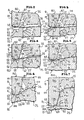
- FIGURE 2 is an enlarged fragmentary schematic cross-sectional view of a draw punch, reform pad, indent ring and lift ring of the press of Fig. 1, and illustrates the punch and die parts in association with a cup-shaped metallic blank after the blank has been cut and drawn to form a cylindrical can body and just prior to forming of the can bottom.
- FIGURE 3 is a fragmentary schematic cross-sectional view of the tooling of Fig. 2, and illustrates a further sequence in the operation of the press during which the draw punch and reform pad move closer toward the lift ring and indent ring with the end panel of the bottom positioned therebetween.
- FIGURE 4 is a fragmentary cross-sectional view of the tooling of Fig. 3, and illustrates a generally convex axial annular end face of the draw punch applying downwardly directed forces to a peripheral outboard portion of the formed can between the cylindrical body and the end panel thereof.
- FIGURE 5 is a fragmentary cross-sectional view of the tooling of Fig. 4, and illustrates a central portion of the end panel clamped between axial end faces of the reform pad and the indent ring.
- FIGURE 6 is a fragmentary schematic cross-sectional view of the tooling of Fig. 5, and illustrates the simultaneously downward movement of the draw punch and the lift ring at which time the peripheral outboard portion of the can or blank is drawn radially inwardly between respective convex and concave opposing surfaces of the draw punch and lift ring to progressively form a frusto-conical wall between a central portion of the end panel and a shallow channel of the can bottom adjacent the cylindrical body.
- FIGURE 7 is a fragmentary schematic cross-sectional view of the tooling of Fig. 6, and illustrates the draw punch at the bottom of its stroke (Fig. 1) and the frusto-conical wall formed into two frusto-conical wall portions.
- FIGURE 8 is fragmentary schematic cross-sectional view of the tooling of Fig. 7, and illustrates two phantom outline positions and a single solid line position of the can bottom during upward movement of the draw punch and lift ring at which time the frusto-conical wall portions are progressively formed into an annular reinforcing bead and an annular stacking bead.
- FIGURE 9 is a fragmentary schematic cross-sectional view of the tooling of Fig. 8, and illustrates the position of the tooling at which the reinforcing bead and the stacking bead have been fully formed.
- FIGURE 10 is a fragmentary schematic cross-sectional view of the tooling of Fig. 9, and illustrates the release of the reformed can.
- FIGURE 11 is a fragmentary cross-sectional view of the can, and illustrates the reinforced pressure-resistant can bottom thereof.
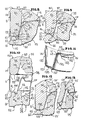
- FIGURE 12 is a fragmentary schematic cross-sectional view of a modified form of tooling at the same position as that illustrated in Fig. 7, and illustrates a modification of the reform pad.
- FIGURE 13 is a fragmentary schematic cross-sectional view of the tooling of Fig. 12, and illustrates the fully reformed can bottom.
- FIGURE 14 is a fragmentary schematic axial cross-sectional view of another modification similar to that of Fig. 2, except the press components are contoured to form a can body with a stacking bead but without a reinforcing bead.
- FIGURE 15 is a fragmentary schematic cross-sectional view of the tooling of Fig. 14, and illustrates a further sequence in the operation of the press.
- FIGURE 16 is a fragmentary cross-sectional view of the tooling of Fig. 15, and illustrates a generally convex axial end face of the draw punch applying downwardly directed forced to a peripheral outboard portion of the body end panel.
- FIGURE 17 is a fragmentary schematic cross-sectional view of the tooling of Fig. 16, and illustrates the position at which a central portion of the can end panel is clamped between axial end faces of the reform pad and the indent ring.
- FIGURE 18 is a enlarged fragmentary schematic cross-sectional view of the tooling of Fig. 17, and illustrates the simultaneous downward movement of the draw punch and the lift ring to progressively form a frusto-conical wall.
- FIGURE 19 is a fragmentary schematic cross-sectional view of the tooling of Fig. 18, and illustrates the draw punch at the bottom of its stroke.
- FIGURE 20 is a fragmentary schematic cross-sectional view of the tooling of Fig. 19, and illustrates two phantom outline positions and a single solid position of the can bottom during upward movement of the draw punch and lift ring to form an annular stacking bead.
- FIGURE 21 is a fragmentary schematic cross-sectional view of the tooling of Fig. 20, and illustrates the position of the tooling at which the reformed stacking bead has been completed.
- FIGURE 22 is a fragmentary schematic cross-sectional view of the tooling of Fig. 21, and illustrates the release of the can from the press.
- FIGURE 23 is a fragmentary cross-sectional view of the totally formed can, and illustrates the bottom including the annular stacking bead thereof.
- The invention will be best understood by first referring to Fig. 1 of the drawings which illustrates a portion of a conventional multi-die double action press which is generally designated by the
reference numeral 10. Typical of such press is that disclosed in U.S. Patent No. 3,908,429 issued September 30, 1975 in the name of Martin M. Gram. Thepress 10 includes a punch 11 and a die 12. The die 12 is a stationary portion of the frame (not shown) of thepress 10 while the punch 11 is reciprocated in a conventional manner, as by eccentrics or cams between a fully closed or bottom dead center position (Fig. 1) and a fully opened position (not shown). In the position shown in Fig. 1, the punch 11 has been moved through its forming stroke during which a flat or shallow cup-shaped blank has been drawn and wall ironed into a can body B, as disclosed in the latter patent. - The die 12 includes a generally cylindrical upwardly opening recess 13 housing a draw die base 14 which is secured to the assembly 12 by a plurality of
hex screws 15 received in a plurality ofcounter-bored bores 16 and threaded in threadedbores 17 of the assembly 12. There are sixsuch bores 16 andhex screws 15 equally spaced about the draw die base 14 and six similarly spaced threadedbores 17 formed in the assembly 12 for securely attaching the draw die base 14 to the assembly 12 within therecess 13. A bottom wall (unnumbered) of the draw die base includes anaxial bore 18 in which is reciprocally moved anupper portion 20 of a knock-outlift ring rod 21. - The bottom wall (unnumbered) of the draw die base 14 also includes four
counterbores 22 of which only one is illustrated in Fig. 1, and a hex screw 23 is received in eachcounterbore 22 and is threaded in a threaded bore 24 of anindent ring 25 seated within a shallow upwardly openingcircular recess 29 of the draw die base 14. Theindent ring 25 and aconvex face 26 thereof clamp the end panel CP in cooperation with aconcave surface 36 of areform pad 35 of the punch 11, as will be described more fully hereinafter. - The
indent ring 25 additionally includes a generally cylindricalouter surface 27, and thesurfaces means 40 for creating unrestrained tensioning of center panel CP of the can or blank B during the formation of a somewhat angulated radius R (Fig. 7) defined by a pair of shoulders or radius portions Rb and Rc spanned by an annular generally flat angled wall portion Rt (Fig. 7). The tensioning means 40 includes a pair ofannular shoulders annular groove 43. The radii of theshoulders annular groove 43 is .010". The distance of the axis for the radius of theshoulder 42 from the axialterminal end face 26 of theindent ring 25 is generally .015" and the distance of the axis of theradius 41 from the axis of theindent ring 25 is approximately 0.976" - 0.977". - A lower portion (unnumbered) of the
indent ring 25 is traversed by a diametric slot 28 (Fig. 1) which transforms a lower end portion of theindent ring 25 into a pair of legs 30, 31. Thediametric slot 28 accommodates reciprocal movement of ahub 105 forming a part of a diametric spider (not shown) of alift ring 60. Each of the legs 30, 31 of theindent ring 25 includes avertical slot lift ring 60. - The base 14 also includes six equally circumferentially spaced
bores 34 and six equally circumferentially spacedblind bores 45. Each of theboxes 34 receives a reduced end portion 46 of alift pin 47 while each of theblind bores 45 houses acompression spring 48. - The compression springs 48 bear against the undersurface of a draw die 70 which cooperates in a conventional manner with a
cutting punch 75 of the punch 11 and a cut edge orannular blanking die 76 carried by adie holder 78 secured in a conventional manner to the bolster block assembly 12 by a plurality of hex socket screws and nuts 81. Upon the descent of thecutting punch 75, upon downward motion imparted to the punch 11, the cooperative interaction of thedraw die 70, thecutting punch 75 and thecut edge 76 results in the peripheral edge of earlier described flat or shallow cup-shaped blank being trimmed with waste material being eventually discarded during normal operations of thepress 10. - The
lift ring 60 includes an outer peripheralcylindrical surface 61 and an inner peripheralcylindrical surface 62. A terminalperipheral end face 64 bridges theperipheral surfaces peripheral end face 64 includes a shallow upwardly opening convex recess 65, a relatively deep axially upwardly openingannular channel 69, an inboard annular axial face orsurface 66 and an outboard annular axial face orsurface 67. Thesurface 66 is radially longer than and slightly above (0.030") thesurface 67. Thecollective surfaces 65 through 67 provide guidance to inward metal flow of a peripheral portion or cylindrical wall PP of the can body B during the downward or forming stroke of the press and a clamping or gripping action during the upward or reforming stroke, as will be described more fully hereinafter. Downward movement is imparted to thelift ring 60 by the descent of thecutting punch 75. During such downward movement, thelift pins 47 are also moved downwardly moving a lift pin disc 91 (Fig. 1) out of contact with abumper retainer plate 92 and further compressing a previously preloadedspring 93 to load thespring 93 to approximately 2,000 lbs. force. The same downward movement of thelift pins 47 and thelift pin disc 91 is transferred to alift pin spacer 94 which compresses acompression spring 95. Thesprings - The
bumper retainer plate 92 is secured to the bolster block assembly 12 by a plurality ofhex socket screws 96 received incounterbores 97 of thebumper retainer plate 92 and threaded in threadedbores 98 of the bolster block assembly 12. The bolster block assembly 12 also includes a threadedbore 101 into which is threaded an enlarged threadedportion 102 of a lift ring knock-out bumper 103 having anaxial bore 104 within which reciprocates the knock-outlift ring rod 21. - The punch 11 includes a conventional blank
punch slide assembly 110 which has mounted thereto a conventional cutting punch holder 111 by means of a blank ram attachment 112 (only on illustrated) and an associatedset screw 113. Thecutting punch 75 is secured in a conventional manner, including a cutting punchholder clamping nut 114, to lower end portion of the cutting punch holder 111. - An inner piston or draw
punch rod 120 is mounted for reciprocal movement within the cutting punch holder 111 and includes abore 121, acounterbore 122 and an internally threadedend portion 123. The internally threadedend portion 123 is threaded to a threadedportion 82 of a stem 83 of adraw punch 80. Thedraw punch 80 includes anaxial bore 84 and acounterbore 85 defined by a peripheral skirt or annular formingmember 86 of thedraw punch 80. Thecounterbore 85 is defined in part by an inner cylindricalperipheral surface 87 which is in intimate sliding contact with a like outer peripheral cylindrical surface 37 (Fig. 2) of thereform pad 35. Thecylindrical surface 37 and the axial end face 36 of thereform pad 35 are bridged bymeans 38 in the form of an angled annular surface setting-off an obtuse angle of approximately 120° with theterminal end face 36. A like obtuse angle is set-off between theperipheral surface 37 and the angledannular surface 38. The means 38 functions to prevent a coating upon the blank B, such as lacquer or enamel, from cracking or being wiped-off and, thus, prevents metal exposure of the eventually formed inner surface of the can body B during the forming and reforming operation. Theannular surface 38 cooperatively functions with a frusto-conical surface 88 of thedraw punch 80 to define therewith and therebetween means for forming an annular downwardly opening and divergingchamber 130 into which the formed radius R (Fig. 7) can be freely reformed without guidance or restraint (See Figs. 8 and 9) during the upward stroke or movement of thelift ring 60 to eventually form an annular reinforcing countersink radius Rr (Fig. 9). - The frusto-
conical surface 88 merges with a pair ofconvex radii annular surface 138. The curvature of the radii/surfaces 136 through 138 corresponds to the curvature of thesurface 65 of thegroove 64 which together therewith provides added guidance to the inward metal flow during the downward or forming stroke when the can body B is formed to its final formed (though not reformed) configuration (Fig. 7). - A hex screw 140 (Fig. 1) is threaded into a threaded bore (unnumbered) of a
draw punch piston 141 having ablind bore 142, a plurality ofseals 143 and aperipheral flange 144 which can bottom against an annularaxial end face 145 of the draw punch stem 83. Thecounterbore 122 is connected through thebore 121 to a supply of fluid pressure, such as a nitrogen cylinder and an associated air amplifier with appropriate valving and controls, which is simply designated by the headed arrow P1. The inner piston or drawpunch rod 120 is likewise urged downwardly by fluidic pressure suitably regulated from the same or a different source as the pressure source P1, and the pressure applied to thedraw punch rod 120 is generally designated by the reference character P2, although pressures P1, P2 can be equal. The pressure P1 can be, for example as low as 600 psi and at 1000 psi, the pressure on thepiston 141 is approximately 1060 psi. The pressure is preferably higher, particularly the pressure P2 exerted in a downward direction upon thedraw punch rod 120 because the latter pressure is transferred during the downward or forming stroke from therod 120 through thedraw punch 80, thelift ring 60 and the lift pins 47 to unseat thelift pin disc 91 and thelift pin spacer 94 and, therefore, load thesprings rod 120 provide the mechanical force to lift therods 47 and thelift ring 60 upwardly to reform the can body B from the position shown in Fig. 7 to that shown in Fig. 9 under a second force greater than the first pressure force P2. - The operation of the
press 10 will now be described with particular reference to Figs. 1 through 11 of the drawings. - It is assumed that the blank punch slide assembly 110 (Fig. 1) of the punch 11 has already been fully retracted upwardly to its open position and thereafter moved downwardly to the position shown in Fig. 2. As noted earlier herein, the can body B of Fig. 2 is formed during the latter-noted downward movement from either a flat metallic blank or a shallow cup-shaped blank as the blank is drawn through the set of dies corresponding to the dies 52 of U.S. Patent No. 3,908,429. During the latter descent, the draw die 70 of the cutting
punch 75 trims the blank and toward the bottom of the punch stroke the can body B is drawn generally to its desired axial length. The sequential steps depicted in Figs. 2 through 9 depict forming and reforming the can bottom approaching the end of the forming stroke. - The means for providing the pressures P1 and/or P2 are activated and the
flange 144 of thedraw punch 141 is bottomed against the annular face 145 (Fig. 1) of the stem 83 of thedraw punch 80. Thus, during the continuous downward movement of thedraw punch 80 and thereform pad 35, therespective surfaces surfaces respective lift ring 60 andindent ring 25, although these surfaces progressively move closer toward each other, as is readily apparent by comparing Figs. 2, 3 and 4. Upper end faces of thelift pin disc 91 and thelift pin spacer 94 are, of course, in abutment with an undersurface (unnumbered) of the bumper retainer plate 92 (Fig. 1) at this time. - As the pressure P2 acts continuously downwardly upon the
rod 120, the latter continues to move thedraw punch 80 in a downward direction causing initial deflection of the center panel CP (Fig. 4) without the center panel CP being at this time clamped between thefaces respective indent ring 25 and thereform pad 35. However, eventually the center panel CP is clamped between thesurfaces - As the
draw punch 80 continues downwardly (Fig. 6), the cylindrical wall PP of the can body B is drawn radially inwardly between thesurfaces - As the
draw punch 80 continues its descent (Fig. 7), the material of the cylindrical wall PP continues to be drawn between thesurfaces 136 through 138 on the one hand and 65 through 67 on the other until the frusto-conical wall FW of Fig. 6 is generally contoured into a pair of frusto-conical walls FW1, FW2 bridged by the radius Rb (Fig. 7). During the latter action, thesurface 65 and thesurfaces 136 through 138 function to guide the inward metal flow of the cylindrical wall PP as it is progressively formed toward the eventually angulated radius R of Fig. 7. From the position of thelift ring 60 shown in Fig. 6 to that shown in Fig. 7, the downward movement of thedraw punch 80 not only forces thelift ring 60 downwardly, but this force or pressure P2 is transferred from thelift ring 60 through the lift pins 47 (Fig. 1) to thelift pin disc 91 and from the latter to thelift pin spacer 94, thus loading bothsprings springs draw punch 80 to reform the can body B to its final configuration, namely, the can 150 (Fig. 11). The angulated radius R (Fig. 7) is, however, first stretched or tensioned toward the bottom of the forming stroke so that a central portion Rt (Figs. 7 through 9) between the radii Rb, Rc is particularly tensioned. The tensioning in the area Rt is believed to provide the marked increase in flexibility of an inner wall portion 152 (Fig. 11) of a center panel 151 immediately adjacent aradius 153 of the completely reformed can 150. At the same time work hardening of the radius portion Rb occurs, and coupled with its eventual reforming into the reinforced countersink radius Rr (Figs. 9 and 10), a "kink" or an increased thickness portion beyond "nominal" thickness is created at a portion of acountersink radius 155, generally between the points L1, L2 of Figs. 9 and 11. Thus, from the position generally shown in Fig. 2 to that shown in Fig. 7, thedraw punch 80 which moved forcibly downwardly by the pressure P2 is effective for exerting forces sufficient to transform the peripheral edge portion of the can body B to the configuration of the formed (though not reformed) can body B of Fig. 7 in which the frusto-conical wall portion is tensioned at Rt and work hardening occurs in the material of the radius Rc. - The reform or return stroke (Fig. 8) is initiated without any change in the position of the blank
punch slide assembly 110 and the cutting punch holder 111, and without in any way reducing the clamping action against the center panel CP of the can body B between thesurfaces respective indent ring 25 and thereform pad 35. As the springer springs 93, 95 urge the lift pins 47 upwardly against the regulated decrease in the pressures P1 and/or P2 (Fig. 8), the annular wall portion AW of the can body B is also clamped or gripped between thesurfaces draw punch 80 and thesurface 65 of thelift ring 60. Progressive upward movement of thelift ring 60 results in two simultaneous and progressive movements of the metal of the can body B between the annular wall AW and the radius Rc (Fig. 8). The frusto-conical wall FW2 is reformed progressively from the position shown in Fig. 7 toward and into (Fig. 8) the annular channel orchamber 130 forming the reinforcing countersink radius or annular bead Rr (Fig. 9), while at the same time the radius R2 (Figs. 7 and 8) and the adjacent unclamped portion of the annular wall AW are progressively reformed into theannular channel 69 of thelift ring 60 forming another reinforcing countersink radius or annular bead Ra (Fig. 9) which in practice is known as a "stacking" bead. The transition that occurs between Figs. 7 and 8 is illustrated by the solid lines representing the initial reforming followed by the phantom outlines and the eventual complete reformed can 150. By comparing Figs. 7 and 8 it can be seen that the radius portion Rc of Fig. 7 is generally reversely progressively formed from the position shown in Fig. 7 to that which it eventually reaches in Fig. 9, while at the same time the radius portion Rt is deformed progressively and without restraint, guidance or confinement into the annular channel orchamber 130 until the reinforcing countersink radius Rr (Fig. 9) is fully formed. However during the movement of thelift ring 60 and thedraw punch 80 as aforesaid between the positions shown in Figs. 8 and 9, the earlier tension portion Rt (Fig. 7) of the radius R tends to deform or bend more readily as opposed to the work hardened portion Rb which characteristically creates a relatively tight radius Rr and the reinforced thickened "kink" therebetween, earlier identified between the points L1, L2 (Fig. 9). - In order to effectively receive the metal of the radius R2 into the
channel 69, the distance between thesurface 36 of thedraw punch 80 and thesurface 65 of thelift ring 60 is such as to readily accommodate and permit the metal in the area of the radius R2 to flow into thechannel 69 as thelift ring 60 progressively rises, as is again best illustrated by the progressively lowermost phantom outline position shown in Fig. 8 followed by the solid line position in this same figure, and eventually the uppermost outlying position in Fig. 8 until the final position of Fig. 9. Obviously, if desired, the downward force or pressure on thedraw punch 80 can be progressively released as thelift ring 60 moves upwardly which assures that the metal of the frusto-conical wall FW1 moves without restraint into not only thechannel 69 but also, of course, into the divergingchamber 130. - Upon completion of the return or reform stroke (Fig. 9), the pressure P1 on the draw punch 141 (Fig. 1) is released or lessened and unclamping of the can body B occurs as the
lift ring 60 continues its upward spring-biased return under the mechanical force of thesprings 93 and/or 95 until the position of Fig. 10 is reached by thelift ring 60. Thereafter, the cutting punch holder 111 is mechanically retracted to its final position at which point the can 150 (Fig. 11) can be conventionally ejected. - Reference is now made to Fig. 11 of the drawings which best illustrates the resultant reinforced pressure-
resistant can 150. The reformed can 150 includes the generally circular concavely outwardly opening central panel or panel portion 151, the flexibleannular wall portion 152 immediately adjacent thepanel radius 153, thepanel radius 153, a frusto-conical peripheral inner wall 154, an annular exteriorly upwardly opening reinforcing countersink, channel radius orbead 155, a frusto-conical peripherallyouter wall 156, an axially projecting radius or "stacking"bead 157, anannular end wall 158, anoutermost radius 159 and a cylindrical body orwall 161. - Variations in the present method and apparatus will become apparent to those skilled in the art, and one such modification in the form of a reversal of the various elements heretofore described is shown in Figs. 12 and 13. In Figs. 12 and 13 identical reference numerals have been provided, except primed, to identify structure identical to that illustrated respectively in Figs. 7 and 9. In this case the reform pad 35ʹ has been modified by altering the overall configuration of adjoining
surfaces 170 through 172 bridging surfaces 36ʹ and 37ʹ. Thesurface 170 is of an angular configuration, similar to thesurface 38 of thereform pad 35. However, thesurface 172 is radially outboard of the corresponding radius 41ʹ of the indent ring 25ʹ, and as a result the annularly downwardly opening chamber 130ʹ abruptly narrows at thecylindrical surface 171. Thus, upon the upward return stroke or reform stroke of the lift ring 60ʹ, the radius Rʹr is "tighter" or closed, as is most readily apparent by comparing the radius Rr of Figs. 9 and 10 with the radius Rʹr of Fig. 13. This results in a more rigid reinforcement of the countersink radius Rʹr or 155ʹ than that provided by the reinforcingcountersink radius 155. Otherwise, the stacking bead 157ʹ of the can 150ʹ is the same as the stacking bead 57 of Fig. 11. - Reference is now made to another variation of the invention best illustrated in Figs. 14 through 22 of the drawings which structurally correspond to the positions of the parts of the punch and die of Figs. 2 through 10, respectively. Accordingly, the parts of the punch and die of Figs. 14 through 22 corresponding generally identically to Figs. 2 through 10 have been identically numbered, though the same have been double primed. These parts include an identical draw punch 80ʺ, an identical lift ring 60ʺ, and an identical lift ring 25ʺ. However, a reform pad 35ʺ differs from the
reform pad 35 only in the absence of the tapered or frusto-conical surface corresponding to thesurface 38 of thereform pad 35. The reform pad 35ʺ includes a shallowgripping surface 236 opposing the gripping surface 26ʺ of the indent ring 25ʺ, aradius 237 and an outercylindrical surface 238, thus creating a relatively shallow chamber 130ʺ. - The draw punch 80ʺ, the reform pad 35ʺ, the lift ring 60ʺ and the indent ring 25ʺ operate through the position shown in Figs. 14 through 22 identically to the operation of the corresponding parts described relative to Figs. 2 through 10, which description is incorporated hereat by reference, but with one exception. In regard to the latter, reference is made to Fig. 19 in which the blank Bʺ excludes the frusto-conical wall portion FW2 of Fig. 7 and instead includes a single generally frusto-conical wall FWʺ1. Accordingly, as the progressive upward movement of the lift ring 60ʺ begins (lower phantom outline position of Fig. 20), the metal of the frusto-conical wall portion FWʹ1 is deformed progressively toward and into (Figs. 20 and 21) the annular channel 69ʺ of the lift ring 60ʺ reforming the reinforcing countersink radius or annular stacking bead Rʺa (Figs. 21 and 22) or 157ʺ (Fig. 23). While metal freely flows in an unrestrained fashion into the annular channel 69ʺ during the reform stroke, the narrow or shallow channel 130ʺ and the position of the frusto-conical wall portion FWʺ1 between the draw punch 80ʺ and the reform pad 35ʺ prevents the metal from entering the channel 130ʺ and precludes the formation of another reinforcing bead corresponding to the bead Rr (Fig. 9) or 155 (Fig. 11) of the
container 150. Therefore, upon the completion of the return or reforming stroke (Figs. 20 and 21), the eventually formed can 150ʺ (Fig. 23) includes the stacking bead 157ʺ but excludes the pressure-resistant bead 155 of the container or can 150 (Fig. 11). - Whilst the method described in relation to Figures 1-14 provides for provision of an inwardly projecting outwardly opening annular bead adjacent the central panel and an outwardly projecting inwardly opening annular stacking bead, a can bottom in which the stacking bead is not provided can readily be formed if the
lift ring 60 is formed without thechannel 69 such that thesurfaces
Claims (11)
Priority Applications (1)
| Application Number | Priority Date | Filing Date | Title |
|---|---|---|---|
| AT87300672T ATE76598T1 (en) | 1986-02-24 | 1987-01-27 | METHOD OF FORMING A ONE PIECE CAN BODY WITH AN END BONDER RADIUS AND/OR A STACKING BEAD. |
Applications Claiming Priority (2)
| Application Number | Priority Date | Filing Date | Title |
|---|---|---|---|
| US06/832,417 US4722215A (en) | 1984-02-14 | 1986-02-24 | Method of forming a one-piece can body having an end reinforcing radius and/or stacking bead |
| US832417 | 1986-02-24 |
Publications (3)
| Publication Number | Publication Date |
|---|---|
| EP0235918A2 true EP0235918A2 (en) | 1987-09-09 |
| EP0235918A3 EP0235918A3 (en) | 1990-02-14 |
| EP0235918B1 EP0235918B1 (en) | 1992-05-27 |
Family
ID=25261580
Family Applications (1)
| Application Number | Title | Priority Date | Filing Date |
|---|---|---|---|
| EP87300672A Expired - Lifetime EP0235918B1 (en) | 1986-02-24 | 1987-01-27 | Method of forming a one-piece can body having an end reinforcing radius and/or stacking bead |
Country Status (6)
| Country | Link |
|---|---|
| US (1) | US4722215A (en) |
| EP (1) | EP0235918B1 (en) |
| JP (1) | JPS62203629A (en) |
| AT (1) | ATE76598T1 (en) |
| DE (1) | DE3779343D1 (en) |
| ZA (1) | ZA87718B (en) |
Cited By (1)
| Publication number | Priority date | Publication date | Assignee | Title |
|---|---|---|---|---|
| US5522248A (en) * | 1993-08-18 | 1996-06-04 | Aluminum Company Of America | Method of forming a metal container body |
Families Citing this family (44)
| Publication number | Priority date | Publication date | Assignee | Title |
|---|---|---|---|---|
| US4991735A (en) * | 1989-05-08 | 1991-02-12 | Aluminum Company Of America | Pressure resistant end shell for a container and method and apparatus for forming the same |
| US4930330A (en) * | 1989-07-27 | 1990-06-05 | Pride Machine Inc. | Double action bottom former |
| US5222385A (en) * | 1991-07-24 | 1993-06-29 | American National Can Company | Method and apparatus for reforming can bottom to provide improved strength |
| US5356256A (en) * | 1992-10-02 | 1994-10-18 | Turner Timothy L | Reformed container end |
| US5477977A (en) * | 1994-05-05 | 1995-12-26 | Reynolds Metals Company | Thin-walled can having a nestable/stackable bottom support ring |
| US5645189A (en) * | 1994-11-21 | 1997-07-08 | Metal Container Corporation | Container end having annular panel with non-uniform radius of curvature |
| US5605069A (en) * | 1995-04-12 | 1997-02-25 | Ball Corporation | Beverage container with wavy transition wall geometry and method for producing the same |
| US6132155A (en) * | 1995-10-23 | 2000-10-17 | Metal Container Corporation | Process for can bottom manufacture for improved strength and material use reduction |
| US5685189A (en) * | 1996-01-22 | 1997-11-11 | Ball Corporation | Method and apparatus for producing container body end countersink |
| US5881593A (en) * | 1996-03-07 | 1999-03-16 | Redicon Corporation | Method and apparatus for forming a bottom-profiled cup |
| US6317832B1 (en) * | 1997-02-21 | 2001-11-13 | Mondex International Limited | Secure multiple application card system and process |
| US6024239A (en) * | 1997-07-03 | 2000-02-15 | American National Can Company | End closure with improved openability |
| US6089072A (en) * | 1998-08-20 | 2000-07-18 | Crown Cork & Seal Technologies Corporation | Method and apparatus for forming a can end having an improved anti-peaking bead |
| US6102243A (en) * | 1998-08-26 | 2000-08-15 | Crown Cork & Seal Technologies Corporation | Can end having a strengthened side wall and apparatus and method of making same |
| EP2497717A1 (en) * | 1999-12-08 | 2012-09-12 | Ball Corporation | Metallic beverage can end with improved chuck wall and countersink |
| US7380684B2 (en) | 1999-12-08 | 2008-06-03 | Metal Container Corporation | Can lid closure |
| US20020113069A1 (en) * | 2000-12-27 | 2002-08-22 | Forrest Randy G. | Can end for a container |
| US6686883B2 (en) * | 2001-06-28 | 2004-02-03 | Micro Ft Co., Ltd. | Antenna |
| US6419110B1 (en) | 2001-07-03 | 2002-07-16 | Container Development, Ltd. | Double-seamed can end and method for forming |
| US6772900B2 (en) * | 2001-08-16 | 2004-08-10 | Rexam Beverage Can Company | Can end |
| US7004345B2 (en) * | 2001-08-16 | 2006-02-28 | Rexam Beverage Can Company | Can end |
| US7556168B2 (en) * | 2001-08-16 | 2009-07-07 | Rexam Beverage Can Company | Can end with fold |
| US7644833B2 (en) * | 2001-08-16 | 2010-01-12 | Rexam Beverage Can Company | Can end |
| US6748789B2 (en) | 2001-10-19 | 2004-06-15 | Rexam Beverage Can Company | Reformed can end for a container and method for producing same |
| KR200289188Y1 (en) | 2002-06-11 | 2002-09-13 | 전정욱 | Readily openable can lid |
| US7500376B2 (en) * | 2004-07-29 | 2009-03-10 | Ball Corporation | Method and apparatus for shaping a metallic container end closure |
| US20060071005A1 (en) * | 2004-09-27 | 2006-04-06 | Bulso Joseph D | Container end closure with improved chuck wall and countersink |
| US7506779B2 (en) * | 2005-07-01 | 2009-03-24 | Ball Corporation | Method and apparatus for forming a reinforcing bead in a container end closure |
| US8875936B2 (en) * | 2007-04-20 | 2014-11-04 | Rexam Beverage Can Company | Can end with negatively angled wall |
| US8011527B2 (en) * | 2007-08-10 | 2011-09-06 | Rexam Beverage Can Company | Can end with countersink |
| US8973780B2 (en) | 2007-08-10 | 2015-03-10 | Rexam Beverage Can Company | Can end with reinforcing bead |
| US20090180999A1 (en) * | 2008-01-11 | 2009-07-16 | U.S. Nutraceuticals, Llc D/B/A Valensa International | Method of preventing, controlling and ameliorating urinary tract infections using cranberry derivative and d-mannose composition |
| PL2252522T3 (en) * | 2008-01-18 | 2016-01-29 | Crown Packaging Technology Inc | Can end |
| PL2161207T3 (en) | 2008-09-04 | 2011-10-31 | Crown Packaging Technology Inc | Can end |
| PL2376347T3 (en) * | 2008-11-11 | 2013-11-29 | Crown Packaging Technology Inc | Method of assembling an easy open can end |
| US9352379B2 (en) * | 2009-04-07 | 2016-05-31 | Rexam Beverage Can Company | Tooling pod for double action can end press |
| US8454292B2 (en) * | 2009-05-14 | 2013-06-04 | Crown Packaging Technology, Inc. | Method of forming a can end having a moveable portion |
| WO2011049775A1 (en) * | 2009-10-21 | 2011-04-28 | Stolle Machinery Company, Llc | Container, and selectively formed cup, tooling and associated method for providing same |
| US9566634B2 (en) | 2010-06-07 | 2017-02-14 | Rexam Beverage Can Company | Can end produced from downgauged blank |
| US8727169B2 (en) | 2010-11-18 | 2014-05-20 | Ball Corporation | Metallic beverage can end closure with offset countersink |
| US9975164B2 (en) * | 2012-05-18 | 2018-05-22 | Stolle Machinery Company, Llc | Container, and selectively formed shell, and tooling and associated method for providing same |
| US9573183B2 (en) | 2012-05-18 | 2017-02-21 | Stolle Machinery Company, Llc | Container, and selectively formed shell, and tooling and associated method for providing same |
| CN107614140B (en) * | 2015-05-27 | 2020-04-14 | 斯多里机械有限责任公司 | Container, selectively shaped shell and tool for providing shell and related method |
| DE102020129484A1 (en) * | 2020-11-09 | 2022-05-12 | Ardagh Metal Beverage Europe Gmbh | Method of manufacturing a metallic container |
Citations (10)
| Publication number | Priority date | Publication date | Assignee | Title |
|---|---|---|---|---|
| US3537291A (en) * | 1967-10-04 | 1970-11-03 | Reynolds Metals Co | Apparatus for and method of forming an end closure for a can |
| NL7405438A (en) * | 1973-04-23 | 1974-10-25 | ||
| US3957005A (en) * | 1974-06-03 | 1976-05-18 | Aluminum Company Of America | Method for making a metal can end |
| US4031837A (en) * | 1976-05-21 | 1977-06-28 | Aluminum Company Of America | Method of reforming a can end |
| US4120419A (en) * | 1976-02-23 | 1978-10-17 | National Steel Corporation | High strength seamless chime can body, sheet metal container for vacuum packs, and manufacture |
| US4151927A (en) * | 1974-07-12 | 1979-05-01 | Reynolds Metals Company | Container construction |
| US4177746A (en) * | 1976-07-29 | 1979-12-11 | Reynolds Metals Company | Method of forming a container |
| US4372720A (en) * | 1980-09-04 | 1983-02-08 | American Can Company | Forming of end closures |
| US4431112A (en) * | 1976-08-20 | 1984-02-14 | Daiwa Can Company, Limited | Drawn and ironed can body and filled drawn and ironed can for containing pressurized beverages |
| EP0153115A2 (en) * | 1984-02-14 | 1985-08-28 | Cmb Packaging (Uk) Limited | Method of and apparatus for forming a reinforced can end |
Family Cites Families (9)
| Publication number | Priority date | Publication date | Assignee | Title |
|---|---|---|---|---|
| US2763228A (en) * | 1952-10-08 | 1956-09-18 | Ball Brothers Co Inc | Lid-making apparatus |
| US3307388A (en) * | 1961-01-16 | 1967-03-07 | Sheffield Corp | Wheel manufacture |
| US3973693A (en) * | 1974-03-12 | 1976-08-10 | Plastona (John Waddington) Limited | Containers for containing carbonated beverages |
| US4037752A (en) * | 1975-11-13 | 1977-07-26 | Coors Container Company | Container with outwardly flexible bottom end wall having integral support means and method and apparatus for manufacturing thereof |
| IT1073811B (en) * | 1976-09-20 | 1985-04-17 | Censuales Angelo | DUAL-ACTION SHEET METAL COLD WORKING DEVICE AND PROCEDURE IN A SINGLE OPERATING PHASE |
| FR2398669A1 (en) * | 1977-07-29 | 1979-02-23 | Carnaud Sa | Preserved food container with pressed bottom - has support ring of defined curvature and height pressed in bottom to provide container base |
| US4109599A (en) * | 1977-11-04 | 1978-08-29 | Aluminum Company Of America | Method of forming a pressure resistant end shell for a container |
| JPS6024735A (en) * | 1983-07-20 | 1985-02-07 | Akiyufueezu Kk | Receiver |
| US4587825A (en) * | 1984-05-01 | 1986-05-13 | Redicon Corporation | Shell reforming method and apparatus |
-
1986
- 1986-02-24 US US06/832,417 patent/US4722215A/en not_active Expired - Fee Related
-
1987
- 1987-01-27 EP EP87300672A patent/EP0235918B1/en not_active Expired - Lifetime
- 1987-01-27 DE DE8787300672T patent/DE3779343D1/en not_active Expired - Lifetime
- 1987-01-27 AT AT87300672T patent/ATE76598T1/en active
- 1987-01-30 ZA ZA87718A patent/ZA87718B/en unknown
- 1987-02-24 JP JP62041244A patent/JPS62203629A/en active Granted
Patent Citations (10)
| Publication number | Priority date | Publication date | Assignee | Title |
|---|---|---|---|---|
| US3537291A (en) * | 1967-10-04 | 1970-11-03 | Reynolds Metals Co | Apparatus for and method of forming an end closure for a can |
| NL7405438A (en) * | 1973-04-23 | 1974-10-25 | ||
| US3957005A (en) * | 1974-06-03 | 1976-05-18 | Aluminum Company Of America | Method for making a metal can end |
| US4151927A (en) * | 1974-07-12 | 1979-05-01 | Reynolds Metals Company | Container construction |
| US4120419A (en) * | 1976-02-23 | 1978-10-17 | National Steel Corporation | High strength seamless chime can body, sheet metal container for vacuum packs, and manufacture |
| US4031837A (en) * | 1976-05-21 | 1977-06-28 | Aluminum Company Of America | Method of reforming a can end |
| US4177746A (en) * | 1976-07-29 | 1979-12-11 | Reynolds Metals Company | Method of forming a container |
| US4431112A (en) * | 1976-08-20 | 1984-02-14 | Daiwa Can Company, Limited | Drawn and ironed can body and filled drawn and ironed can for containing pressurized beverages |
| US4372720A (en) * | 1980-09-04 | 1983-02-08 | American Can Company | Forming of end closures |
| EP0153115A2 (en) * | 1984-02-14 | 1985-08-28 | Cmb Packaging (Uk) Limited | Method of and apparatus for forming a reinforced can end |
Cited By (1)
| Publication number | Priority date | Publication date | Assignee | Title |
|---|---|---|---|---|
| US5522248A (en) * | 1993-08-18 | 1996-06-04 | Aluminum Company Of America | Method of forming a metal container body |
Also Published As
| Publication number | Publication date |
|---|---|
| EP0235918B1 (en) | 1992-05-27 |
| JPH0378167B2 (en) | 1991-12-12 |
| EP0235918A3 (en) | 1990-02-14 |
| ATE76598T1 (en) | 1992-06-15 |
| JPS62203629A (en) | 1987-09-08 |
| US4722215A (en) | 1988-02-02 |
| ZA87718B (en) | 1987-09-30 |
| DE3779343D1 (en) | 1992-07-02 |
Similar Documents
| Publication | Publication Date | Title |
|---|---|---|
| EP0235918B1 (en) | Method of forming a one-piece can body having an end reinforcing radius and/or stacking bead | |
| US4606472A (en) | Reinforced can end | |
| US4571978A (en) | Method of and apparatus for forming a reinforced can end | |
| US5528815A (en) | Clinching tool for sheet metal joining | |
| US3786667A (en) | Apparatus for and method of making a nestable container | |
| JP3012117B2 (en) | Controlled material flow hydraulic forming method and apparatus | |
| US5024077A (en) | Method for forming container with profiled bottom | |
| US5435049A (en) | Apparatus for joining sheet material | |
| US5208973A (en) | Apparatus for joining sheet material | |
| US4865506A (en) | Apparatus for reforming an end shell | |
| JP2008508104A (en) | Method and apparatus for shaping a terminal closure member of a metal container | |
| JPH0424129B2 (en) | ||
| US3435653A (en) | Forming method and apparatus | |
| EP0523134B1 (en) | Clinching tool for sheet metal joining | |
| JPH0255127B2 (en) | ||
| US7086265B2 (en) | Method for controlling the material flow during the deep-drawings of sheet metal, and deep-drawing tool | |
| US6014883A (en) | Apparatus and method for forming cup-shaped members | |
| US20060096075A1 (en) | Clinching tool, die and method for use thereof | |
| US5819573A (en) | Hydraulic forming of workpieces from sheet metal | |
| US20010013240A1 (en) | Tool cartridge having an elastic matrix | |
| US5906038A (en) | Method of mounting belt fasteners on conveyor belts | |
| DE2432300A1 (en) | METHOD OF PRESS FORMING A BLANK FROM DEFORMABLE MATERIAL AND MOLDING PRESS | |
| CA2586776A1 (en) | Clinching tool, die and method for use thereof | |
| JP2001105081A (en) | Closed forging apparatus | |
| US113044A (en) | Improvement in the methods of banding compressed wood |
Legal Events
| Date | Code | Title | Description |
|---|---|---|---|
| PUAI | Public reference made under article 153(3) epc to a published international application that has entered the european phase |
Free format text: ORIGINAL CODE: 0009012 |
|
| 17P | Request for examination filed |
Effective date: 19870203 |
|
| AK | Designated contracting states |
Kind code of ref document: A2 Designated state(s): AT BE CH DE ES FR GB GR IT LI LU NL SE |
|
| RAP1 | Party data changed (applicant data changed or rights of an application transferred) |
Owner name: MB GROUP PLC |
|
| RAP1 | Party data changed (applicant data changed or rights of an application transferred) |
Owner name: CMB PACKAGING (UK) LIMITED |
|
| PUAL | Search report despatched |
Free format text: ORIGINAL CODE: 0009013 |
|
| AK | Designated contracting states |
Kind code of ref document: A3 Designated state(s): AT BE CH DE ES FR GB GR IT LI LU NL SE |
|
| RAP1 | Party data changed (applicant data changed or rights of an application transferred) |
Owner name: CMB FOODCAN PLC |
|
| 17Q | First examination report despatched |
Effective date: 19910201 |
|
| GRAA | (expected) grant |
Free format text: ORIGINAL CODE: 0009210 |
|
| AK | Designated contracting states |
Kind code of ref document: B1 Designated state(s): AT BE CH DE ES FR GB GR IT LI LU NL SE |
|
| PG25 | Lapsed in a contracting state [announced via postgrant information from national office to epo] |
Ref country code: IT Free format text: LAPSE BECAUSE OF FAILURE TO SUBMIT A TRANSLATION OF THE DESCRIPTION OR TO PAY THE FEE WITHIN THE PRE;WARNING: LAPSES OF ITALIAN PATENTS WITH EFFECTIVE DATE BEFORE 2007 MAY HAVE OCCURRED AT ANY TIME BEFORE 2007. THE CORRECT EFFECTIVE DATE MAY BE DIFFERENT FROM THE ONE RECORDED.SCRIBED TIME-LIMIT Effective date: 19920527 Ref country code: NL Effective date: 19920527 Ref country code: AT Effective date: 19920527 Ref country code: SE Effective date: 19920527 Ref country code: LI Effective date: 19920527 Ref country code: FR Effective date: 19920527 Ref country code: CH Effective date: 19920527 Ref country code: BE Effective date: 19920527 Ref country code: GR Free format text: LAPSE BECAUSE OF FAILURE TO SUBMIT A TRANSLATION OF THE DESCRIPTION OR TO PAY THE FEE WITHIN THE PRESCRIBED TIME-LIMIT Effective date: 19920527 |
|
| REF | Corresponds to: |
Ref document number: 76598 Country of ref document: AT Date of ref document: 19920615 Kind code of ref document: T |
|
| REF | Corresponds to: |
Ref document number: 3779343 Country of ref document: DE Date of ref document: 19920702 |
|
| REG | Reference to a national code |
Ref country code: CH Ref legal event code: PL |
|
| PG25 | Lapsed in a contracting state [announced via postgrant information from national office to epo] |
Ref country code: ES Free format text: LAPSE BECAUSE OF FAILURE TO SUBMIT A TRANSLATION OF THE DESCRIPTION OR TO PAY THE FEE WITHIN THE PRESCRIBED TIME-LIMIT Effective date: 19920907 |
|
| EN | Fr: translation not filed | ||
| NLV1 | Nl: lapsed or annulled due to failure to fulfill the requirements of art. 29p and 29m of the patents act | ||
| PG25 | Lapsed in a contracting state [announced via postgrant information from national office to epo] |
Ref country code: LU Free format text: LAPSE BECAUSE OF NON-PAYMENT OF DUE FEES Effective date: 19930131 |
|
| PLBE | No opposition filed within time limit |
Free format text: ORIGINAL CODE: 0009261 |
|
| STAA | Information on the status of an ep patent application or granted ep patent |
Free format text: STATUS: NO OPPOSITION FILED WITHIN TIME LIMIT |
|
| 26N | No opposition filed | ||
| PGFP | Annual fee paid to national office [announced via postgrant information from national office to epo] |
Ref country code: GB Payment date: 19951219 Year of fee payment: 10 |
|
| PGFP | Annual fee paid to national office [announced via postgrant information from national office to epo] |
Ref country code: DE Payment date: 19951220 Year of fee payment: 10 |
|
| PG25 | Lapsed in a contracting state [announced via postgrant information from national office to epo] |
Ref country code: GB Effective date: 19970127 |
|
| GBPC | Gb: european patent ceased through non-payment of renewal fee |
Effective date: 19970127 |
|
| PG25 | Lapsed in a contracting state [announced via postgrant information from national office to epo] |
Ref country code: DE Effective date: 19971001 |