EP0238200A2 - Light tube protector and tube - Google Patents
Light tube protector and tube Download PDFInfo
- Publication number
- EP0238200A2 EP0238200A2 EP87301274A EP87301274A EP0238200A2 EP 0238200 A2 EP0238200 A2 EP 0238200A2 EP 87301274 A EP87301274 A EP 87301274A EP 87301274 A EP87301274 A EP 87301274A EP 0238200 A2 EP0238200 A2 EP 0238200A2
- Authority
- EP
- European Patent Office
- Prior art keywords
- tube
- light tube
- light
- sheath
- protector
- Prior art date
- Legal status (The legal status is an assumption and is not a legal conclusion. Google has not performed a legal analysis and makes no representation as to the accuracy of the status listed.)
- Withdrawn
Links
Images

Classifications
-
- H—ELECTRICITY
- H01—ELECTRIC ELEMENTS
- H01J—ELECTRIC DISCHARGE TUBES OR DISCHARGE LAMPS
- H01J61/00—Gas-discharge or vapour-discharge lamps
- H01J61/02—Details
- H01J61/30—Vessels; Containers
- H01J61/34—Double-wall vessels or containers
-
- H—ELECTRICITY
- H01—ELECTRIC ELEMENTS
- H01J—ELECTRIC DISCHARGE TUBES OR DISCHARGE LAMPS
- H01J5/00—Details relating to vessels or to leading-in conductors common to two or more basic types of discharge tubes or lamps
- H01J5/02—Vessels; Containers; Shields associated therewith; Vacuum locks
- H01J5/03—Arrangements for preventing or mitigating effects of implosion of vessels or containers
Definitions
- This invention relates to a light tube protector.
- light tube is intended to cover all types of fluorescent light source in which a glass envelope of tubular form encloses a low-pressure gas, through which an electric discharge is maintained to emit light which may be in the visible or ultraviolet spectral range.
- the invention is concerned with relatively low power light tubes, typically of less than 200 Watts, rather than high power industrial process light sources which emit considerable heat.
- the invention was primarily devised for use with ultra violet light sources used in sun beds and solaria. However, it may equally be applicable to conventional fluorescent lighting tubes.
- Light tubes may be of substantial length, for example l.8 metres long, and have a tubular glass envelope containing a suitable gas at below atmospheric pressure. If a tube is damaged it may collapse inwardly or "implode", scattering slivers of glass with considerable force.
- Light tubes are carefully manufactured to high standards so that shattering of the tube is a rare occurrence but nevertheless it can happen and is particularly hazardous in some circumstances.
- the tubes may be only a short distance away from the user who would be unprotected if one of the tubes were to shatter in use.
- moving parts may approach lighting units with a risk of the tubes being struck and damaged.
- a light tube protector comprising a sheath of flexible transparent or translucent sheet-like plastics material which is adapted to contact a light tube and at least partly to enclose it.
- the sheath of plastics material is tubular.
- the sheath may be in the form of a flat sheet adapted to be wrapped around the tube and secured.
- the sheath may be deposited directly from molten plastics material or a solution of a plastics material.
- the surface of the sheath may have continuous contact with the light tube. Alternatively, it may contact the light tube at regularly spaced positions or may loosely surround the light tube and make contact at random positions.
- Contact at spaced positions can be achieved by providing surface ridges or other formations on the inner surface of the sheath of plastics material, or by separate spacers.
- the sheet may be apertured to define a network of contact points.
- the plastics material may be polyvinyl chloride (PVC), acrylic, cellulose or polyethylene.
- the plastics material may be tinted to provide colouring effects or may include pigments adapted to absorb particular parts of the spectrum emitted by the light tube.
- Partial transparencies may be inserted between the sheet and the tube carrying indicia such as instructions for use, advertising material or a name or trade mark.
- the plastics material itself may also be printed prior to being applied to the light tube.
- FIG. l a simple form of light tube protector is illustrated.
- a loose tubular sheath l0 of polyethylene film is provided.
- a light tube ll is inserted within the polyethlene sheath l0 so that only the end caps l2 of the tube project. The light tube is then used in the normal manner.
- the loose polyethylene sleeve may be secured in place at the ends of the tube, for example by adhesive on the tube, adhesive tape applied externally, or by being tied in position by an external tie.
- External circlips or internally-disposed expanding fixing rings may also be used for securing the sleeve to the tube, the latter also serving as spacers.
- FIGS 2 and 3 of the drawings illustrate an alternative form of light tube protector.
- a PVC sleeve l4 which may be an extrusion, is placed over the light tube and heat is applied either externally, or by the tube itself being operated, which causes the PVC sleeve l4 to shrink onto the surface of the tube ll.
- This sleeve l4 contacts the surface of the tube so that, in effect, the PVC is laminated onto the tube.
- Spacers in the form of internal ribs or formations l5 can be provided in the sleeve l4, during extrusion. Where such spacers are provided, contact is made between the PVC extrusion and the light tube but the rest of the extrusion is slightly spaced from the light tube. This reduces the tendency for further shrinkage of the extru sion when the light tube is used and its surface becomes warm.
- the spacers also allow ventilation of the tube.
- Figure 4 of the drawings illustrates an alternative form of protector being placed onto a light tube.
- a tubular polyvinyl chloride skin l6 is expanded, with compressed air introduced at the end l7 of the sleeve for example, and the light tube ll is fed into the expanded PVC sleeve l6. The air pressure is released so that the PVC skin is restored to its normal unexpanded size and contacts the light tube.
- a semi-flexible extruded acrylic sleeve is slid onto the tube. It may be a close sliding fit or may have integral internal spacers formed during extrusion.
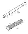
- Figure 5 of the drawings illustrates an alternative semi-flexible acrylic sleeve which is provided with perforations.
- the sheet l8 therefore takes on the characteristics of a "net" which will serve to contain a shattering light tube without entirely enclosing it.
- a perforated plastics material is used, there is unlikely to be significant absorption of light from the tube.
- the characteristics of the light may be altered by the plastics material, for example to give a warmer tint to fluorescent light or to absorb some part of the spectrum of an ultraviolet emitter. In this case, no perforations would be provided in the plastics material.
- the sheath is made of a self-shrinking material such as cellulose.
- a self-shrinking material such as cellulose.
- This has the property of expanding by absorption when soaked in water, returning to its normal size on drying.
- a protector of such a self-shrinking material has the advantage that it can be supplied for fitment to existing tubes by the end user, or to a distributor or warehouse outlet for fitment to standard light tubes, rather than being applied to the tubes by the manufacturer.
- Cellulose can also be printed in one or full colour with instructions or a trade mark picture or pattern for example.
- a sheath of another material such as PVC there may be some advantage in using self-shrinking tubular end caps of cellulose for instance, to secure the sheath to the light tube without other fixing. In particular, this serves to cover any gap between the sheath and the end caps.
- Such a gap might exist using some plastics materials which are excellent for the transmission of ultra violet light but which may not withstand the increased temperature occurring at each end of the light tube in use.
- the gap may also be closed by a metal or ceramic cylinder section which may be moulded or extruded to connect the circular metal terminal fitting of the light tube to the plastics material. This must be done in such a way that if the light tube is broken, the glass remains contained.
- the glass envelope of the light tube tends to become warm in use and it is therefore necessary to select the plastics material and the type of construction carefully so that the protection afforded by the plastics is retained throughout the life of the tube.
- grades of plastics having resistance to ultraviolet degradation are to be preferred.
- the use of spacers in the form of ribs or wrinkles inside the plastics material can extend the life to be expected from it because the plastics material only contacts the tube at the position of the spacers.
- spacers may be initially integral with the plastics sleeve.
- Separate spacers may be put on the light tube before the plastics material is added.
- these may comprise rings or a spiral of plastics or metal mounted on the tube.
- the invention is not suitable for application to high powered tubes which generate very large quantities of heat, such as those used in applying ultra-violet light in industrial processes. In this case, it is frequently necessary to provide water jackets and similar assisted cooling for the light tube.
- the type of protector envisaged by the present invention is not appropriate in these cases and is intended only for use with light tubes of relatively low power, typically less than 200 Watts, reaching no more than l20° Celsius.
- the invention is not limited to light fitments in the form of straight tubes but also covers curved, coiled or circular fluorescent lamps of generally known type and coloured display tubes of neon and similar types.
- plastics material While it is convenient for the plastics material to be in a tubular form, a similar effect may be achieved using a laminar sheet which is wrapped round the light source and secured in position by adhesive, by adhesive tape or mechanically by tying or clipping.
- the film may be of an adhesive type which will adhere directly to the tube or of a self-adhering type which can be secured in position by overlapping the edges of the sheet about the light tube.
- the light tube can be dipped in a molten plastics material or a solution of a plastics material in a suitable fast evaporating solvent.
Landscapes
- Vessels And Coating Films For Discharge Lamps (AREA)
Abstract
A protector for a light tube, particularly an ultra violet sun bed lamp or fluorescent lighting tube is made of a flexible plastics material such as PVC, acrylic or polyethylene and encloses the tube, making contact with it at least at spaced positions, so as to contain any glass fragments if the tube should shatter. Several embodiments are described including the use of loose polyethylene sleeve (l0) retained by circlips (l3) or an extruded acrylic tube (l4) having internal ribs (l5) providing partial spacing from the surface of the light tube (ll), the acrylic sheath being extruded over sized and shrunk onto the light tube by the application of heat applied either externally or using the tube itself as a heat source. In an alternative form, a flexible PVC sleeve (l6) is expanded by compressed air so that the light tube (ll) can be inserted, the sleeve then returning to its normal size. In a further alternative, a self-shrinking material such as cellulose is used in extruded form, soaked in water to expand it onto the light tube and dried to shrink onto the surface of the tube.
Description
- This invention relates to a light tube protector.
- The expression "light tube" is intended to cover all types of fluorescent light source in which a glass envelope of tubular form encloses a low-pressure gas, through which an electric discharge is maintained to emit light which may be in the visible or ultraviolet spectral range.
- The invention is concerned with relatively low power light tubes, typically of less than 200 Watts, rather than high power industrial process light sources which emit considerable heat. The invention was primarily devised for use with ultra violet light sources used in sun beds and solaria. However, it may equally be applicable to conventional fluorescent lighting tubes.
- Light tubes may be of substantial length, for example l.8 metres long, and have a tubular glass envelope containing a suitable gas at below atmospheric pressure. If a tube is damaged it may collapse inwardly or "implode", scattering slivers of glass with considerable force.
- Light tubes are carefully manufactured to high standards so that shattering of the tube is a rare occurrence but nevertheless it can happen and is particularly hazardous in some circumstances. For example, in sun beds, the tubes may be only a short distance away from the user who would be unprotected if one of the tubes were to shatter in use. In a factory, moving parts may approach lighting units with a risk of the tubes being struck and damaged.
- It is an object of the present invention to provide a protector for light tubes which overcomes or reduces the possibility of injury or glass contamination if a light tube shatters in use or during handling.
- According to the invention there is provided a light tube protector comprising a sheath of flexible transparent or translucent sheet-like plastics material which is adapted to contact a light tube and at least partly to enclose it.
- It is known to use a rigid plastics diffuser on a light tube and to provide a rigid transparent acrylic cover plate on a sunbed overlying the ultraviolet generating tubes. This type of rigid covering, separated from the light tubes themselves does not form part of the present invention.
- Preferably, the sheath of plastics material is tubular.
- Alternatively the sheath may be in the form of a flat sheet adapted to be wrapped around the tube and secured. As a further alternative, the sheath may be deposited directly from molten plastics material or a solution of a plastics material.
- The surface of the sheath may have continuous contact with the light tube. Alternatively, it may contact the light tube at regularly spaced positions or may loosely surround the light tube and make contact at random positions.
- Contact at spaced positions can be achieved by providing surface ridges or other formations on the inner surface of the sheath of plastics material, or by separate spacers. Alternatively, the sheet may be apertured to define a network of contact points.
- The plastics material may be polyvinyl chloride (PVC), acrylic, cellulose or polyethylene.
- The plastics material may be tinted to provide colouring effects or may include pigments adapted to absorb particular parts of the spectrum emitted by the light tube.
- Partial transparencies may be inserted between the sheet and the tube carrying indicia such as instructions for use, advertising material or a name or trade mark.
- The plastics material itself may also be printed prior to being applied to the light tube.
- The invention may take a number of forms which will now be described in more detail by way of example only with reference to the accompanying drawings in which:-
- FIGURE l is a perspective view of a light tube having a first form of protector.
- FIGURE 2 is a similar perspective view of a light tube having a second form of protector.
- FIGURE 3 is a section on the line 3-3 of Figure 3.
- FIGURE 4 illustrates a stage in inserting a light tube into a further form of protector.
- FIGURE 5 is a further embodiment of protector.
- Referring firstly to Figure l, a simple form of light tube protector is illustrated. In this simple form a loose tubular sheath l0 of polyethylene film is provided. A light tube ll is inserted within the polyethlene sheath l0 so that only the end caps l2 of the tube project. The light tube is then used in the normal manner.
- If the light tube is broken in use or during handling, particles of glass are either contained by the sleeve or, if the sleeve itself is damaged, their scattering range and velocity are reduced.
- The loose polyethylene sleeve may be secured in place at the ends of the tube, for example by adhesive on the tube, adhesive tape applied externally, or by being tied in position by an external tie. External circlips or internally-disposed expanding fixing rings may also be used for securing the sleeve to the tube, the latter also serving as spacers.
- In this example shown in Figure l, external circlips l3 are used to secure the sleeve l0 to the tube ll.
- Figures 2 and 3 of the drawings illustrate an alternative form of light tube protector. In this second version a PVC sleeve l4, which may be an extrusion, is placed over the light tube and heat is applied either externally, or by the tube itself being operated, which causes the PVC sleeve l4 to shrink onto the surface of the tube ll. This sleeve l4 contacts the surface of the tube so that, in effect, the PVC is laminated onto the tube.
- Spacers in the form of internal ribs or formations l5 can be provided in the sleeve l4, during extrusion. Where such spacers are provided, contact is made between the PVC extrusion and the light tube but the rest of the extrusion is slightly spaced from the light tube. This reduces the tendency for further shrinkage of the extru sion when the light tube is used and its surface becomes warm.
- The spacers also allow ventilation of the tube.
- Figure 4 of the drawings illustrates an alternative form of protector being placed onto a light tube. In this example, a tubular polyvinyl chloride skin l6 is expanded, with compressed air introduced at the end l7 of the sleeve for example, and the light tube ll is fed into the expanded PVC sleeve l6. The air pressure is released so that the PVC skin is restored to its normal unexpanded size and contacts the light tube.
- In a fourth example (not illustrated) a semi-flexible extruded acrylic sleeve is slid onto the tube. It may be a close sliding fit or may have integral internal spacers formed during extrusion.
- Figure 5 of the drawings illustrates an alternative semi-flexible acrylic sleeve which is provided with perforations. The sheet l8 therefore takes on the characteristics of a "net" which will serve to contain a shattering light tube without entirely enclosing it. Where a perforated plastics material is used, there is unlikely to be significant absorption of light from the tube. However, in some circumstances it may actually be desirable for the characteristics of the light to be altered by the plastics material, for example to give a warmer tint to fluorescent light or to absorb some part of the spectrum of an ultraviolet emitter. In this case, no perforations would be provided in the plastics material.
- In a further embodiment, not shown in the drawings, the sheath is made of a self-shrinking material such as cellulose. This has the property of expanding by absorption when soaked in water, returning to its normal size on drying. A protector of such a self-shrinking material has the advantage that it can be supplied for fitment to existing tubes by the end user, or to a distributor or warehouse outlet for fitment to standard light tubes, rather than being applied to the tubes by the manufacturer. Cellulose can also be printed in one or full colour with instructions or a trade mark picture or pattern for example.
- Where a sheath of another material such as PVC is used, there may be some advantage in using self-shrinking tubular end caps of cellulose for instance, to secure the sheath to the light tube without other fixing. In particular, this serves to cover any gap between the sheath and the end caps. Such a gap might exist using some plastics materials which are excellent for the transmission of ultra violet light but which may not withstand the increased temperature occurring at each end of the light tube in use. The gap may also be closed by a metal or ceramic cylinder section which may be moulded or extruded to connect the circular metal terminal fitting of the light tube to the plastics material. This must be done in such a way that if the light tube is broken, the glass remains contained.
- The glass envelope of the light tube tends to become warm in use and it is therefore necessary to select the plastics material and the type of construction carefully so that the protection afforded by the plastics is retained throughout the life of the tube. In particular, grades of plastics having resistance to ultraviolet degradation are to be preferred. The use of spacers in the form of ribs or wrinkles inside the plastics material can extend the life to be expected from it because the plastics material only contacts the tube at the position of the spacers.
- It is not necessary for the spacers to be initially integral with the plastics sleeve. Separate spacers may be put on the light tube before the plastics material is added. For example, these may comprise rings or a spiral of plastics or metal mounted on the tube.
- The invention is not suitable for application to high powered tubes which generate very large quantities of heat, such as those used in applying ultra-violet light in industrial processes. In this case, it is frequently necessary to provide water jackets and similar assisted cooling for the light tube. The type of protector envisaged by the present invention is not appropriate in these cases and is intended only for use with light tubes of relatively low power, typically less than 200 Watts, reaching no more than l20° Celsius.
- In conventional ultra violet sun bed tubes and fluorescent lighting tubes it has been found experimentally that, although the surface of the glass envelope of the light tube becomes warm in use, its temperature is sufficiently low to prevent rapid deterioration of the surrounding plastics protector. Thus, surprisingly, a fluorescent light tube or ultra violet lamp can be protected by the means described above without overheating. Direct contact between the plastics sheet and the tube in particular avoids entrapment of an air insulating layer.
- It will be appreciated that the invention is not limited to light fitments in the form of straight tubes but also covers curved, coiled or circular fluorescent lamps of generally known type and coloured display tubes of neon and similar types.
- While it is convenient for the plastics material to be in a tubular form, a similar effect may be achieved using a laminar sheet which is wrapped round the light source and secured in position by adhesive, by adhesive tape or mechanically by tying or clipping. The film may be of an adhesive type which will adhere directly to the tube or of a self-adhering type which can be secured in position by overlapping the edges of the sheet about the light tube.
- As a further alternative, the light tube can be dipped in a molten plastics material or a solution of a plastics material in a suitable fast evaporating solvent.
Claims (11)
1. A light tube protector characterised in that it comprises a sheath of flexible transparent or translucent sheet-like plastics material which is adapted to contact the light tube and at least partly to enclose it.
2. A protector according to Claim l further characterised in that the sheath of plastics material is tubular.
3. A protector according to Claim l or Claim 2 further characterised in that the surface of the sheath has continuous contact with the light tube.
4. A protector according to Claim l or Claim 2 further characterised in that the sheath contacts the light tube at spaced positions.
5. A protector according to Claim 4 further characterised in that contact is provided at spaced positions by integral or separate spacers.
6. A protector according to Claim 4 further characterised in that the sheath is apertured to define a network of contact points at which it is adapted to contact the tube.
7. A protector according to any preceding claim and further characterised in that it is made of a plastics material selected from : polyvinyl chloride (PVC); acrylic; polyethylene; cellulose.
8. A protector according to any one of Claims l to 7 further characterised in that the plastics material includes pigments adapted to absorb particular parts of the spectrum emitted by the light tube for which it is intended.
9. A light tube characterised in that it has a protector according to any one of Claims l to 8.
l0. A light tube according to Claim 9 and further characterised in that it comprises an ultra violet sun lamp tube.
11. A light tube according to Claim 9 and further characterised in that it comprises a fluorescent light tube emitting visible light.
Applications Claiming Priority (2)
| Application Number | Priority Date | Filing Date | Title |
|---|---|---|---|
| GB8604117 | 1986-02-19 | ||
| GB868604117A GB8604117D0 (en) | 1986-02-19 | 1986-02-19 | Light tube protector |
Publications (2)
| Publication Number | Publication Date |
|---|---|
| EP0238200A2 true EP0238200A2 (en) | 1987-09-23 |
| EP0238200A3 EP0238200A3 (en) | 1989-08-23 |
Family
ID=10593332
Family Applications (1)
| Application Number | Title | Priority Date | Filing Date |
|---|---|---|---|
| EP87301274A Withdrawn EP0238200A3 (en) | 1986-02-19 | 1987-02-13 | Light tube protector and tube |
Country Status (2)
| Country | Link |
|---|---|
| EP (1) | EP0238200A3 (en) |
| GB (2) | GB8604117D0 (en) |
Cited By (21)
| Publication number | Priority date | Publication date | Assignee | Title |
|---|---|---|---|---|
| EP0890350A1 (en) | 1997-07-08 | 1999-01-13 | The Procter & Gamble Company | Disposable absorbent articles with clothlike feel backsheet having zoned breathability and process for making such backsheets |
| EP1303868A1 (en) * | 2000-07-24 | 2003-04-23 | Inc. Thermoplastic Processes | Shatterproofing of fluorescent lamps |
| US6573423B1 (en) | 1997-06-25 | 2003-06-03 | The Procter & Gamble Company | Disposable absorbent articles maintaining low vapor phase moisture content |
| WO2003059224A1 (en) | 2001-12-28 | 2003-07-24 | Sca Hygiene Products Ab | Absorbent article |
| US7172585B2 (en) | 2001-07-03 | 2007-02-06 | Sca Hygiene Products Ab | Absorbent product |
| WO2007123491A1 (en) * | 2006-04-21 | 2007-11-01 | Daniel Muessli | An electric light |
| US7481802B2 (en) | 2001-12-28 | 2009-01-27 | Sca Hygiene Products Ab | Absorbent article |
| WO2009074008A1 (en) * | 2007-11-30 | 2009-06-18 | Zhaoyang Jin | A chemiluminescent drugs storing device with protection casing and chemiluminescent device using the same |
| US7662138B2 (en) | 2001-12-28 | 2010-02-16 | Sca Hygiene Products Ab | Absorbent article |
| US7799007B2 (en) | 2001-12-28 | 2010-09-21 | Sca Hygiene Products Ab | Absorbent article with two-piece construction and method of making the same |
| US20110291563A1 (en) * | 2010-05-26 | 2011-12-01 | General Electric Company | Safety protection solution for compact fluorescent lamps |
| US8138388B2 (en) | 1994-11-28 | 2012-03-20 | The Procter & Gamble Company | Absorbent article and method for maintaining or improving skin health |
| WO2016065008A1 (en) | 2014-10-21 | 2016-04-28 | The Procter & Gamble Company | Method of improving skin appearance |
| WO2017070077A1 (en) | 2015-10-22 | 2017-04-27 | The Procter & Gamble Company | Barrier patch of a foamed film and methods of improving skin appearance |
| WO2018129493A1 (en) | 2017-01-09 | 2018-07-12 | The Procter & Gamble Company | Barrier patch with soluble film |
| WO2018129495A1 (en) | 2017-01-09 | 2018-07-12 | The Procter & Gamble Company | Barrier patch with soluble film and methods of improving skin appearance |
| WO2018129494A1 (en) | 2017-01-09 | 2018-07-12 | The Procter & Gamble Company | Barrier patch with soluble film and methods of improving skin appearance |
| WO2018237214A1 (en) | 2017-06-22 | 2018-12-27 | The Procter & Gamble Company | Beauty care films including a water-soluble layer and a vapor-deposited coating |
| WO2019183010A1 (en) | 2018-03-19 | 2019-09-26 | The Procter & Gamble Company | Method of making a barrier patch with soluble film |
| US10537499B2 (en) | 2015-10-22 | 2020-01-21 | The Procter & Gamble Company | Barrier patch of a foamed film and methods of improving skin appearance |
| US10576023B2 (en) | 2015-10-22 | 2020-03-03 | The Procter & Gamble Company | Barrier patch of a foamed film and methods of improving skin appearance |
Families Citing this family (3)
| Publication number | Priority date | Publication date | Assignee | Title |
|---|---|---|---|---|
| US5064553A (en) * | 1989-05-18 | 1991-11-12 | Colgate-Palmolive Co. | Linear-viscoelastic aqueous liquid automatic dishwasher detergent composition |
| US5053158A (en) * | 1989-05-18 | 1991-10-01 | Colgate-Palmolive Company | Linear viscoelastic aqueous liquid automatic dishwasher detergent composition |
| US5124618A (en) * | 1989-11-16 | 1992-06-23 | Matsushita Electronics Corporation | Shatter-proof fluorescent lamp |
Citations (4)
| Publication number | Priority date | Publication date | Assignee | Title |
|---|---|---|---|---|
| FR1382617A (en) * | 1964-02-14 | 1964-12-18 | Tishman Res Corp | Discharge lamp devices |
| US4048537A (en) * | 1976-06-04 | 1977-09-13 | Gte Sylvania Incorporated | Protective ultraviolet-transmitting sleeve for fluorescent lamp |
| US4147947A (en) * | 1978-01-31 | 1979-04-03 | Westinghouse Electric Corp. | Fluorescent lamp with integral thermal-insulating plastic jacket |
| EP0104594A2 (en) * | 1982-09-23 | 1984-04-04 | GTE Products Corporation | Double-enveloped lamp |
Family Cites Families (8)
| Publication number | Priority date | Publication date | Assignee | Title |
|---|---|---|---|---|
| BE435108A (en) * | 1938-06-27 | |||
| GB753230A (en) * | 1953-08-28 | 1956-07-18 | Cecil Arthur John King | Improvements in and relating to electric indicator lamps |
| GB852728A (en) * | 1959-07-31 | 1960-11-02 | Stavros George Martoudis | Improvements in or relating to electrical discharge tubes |
| GB1029147A (en) * | 1963-02-15 | 1966-05-11 | Tishman Res Corp | Vapor lamp units |
| US3426234A (en) * | 1966-02-15 | 1969-02-04 | Aiden Kk | Explosion-proof fluorescent lamp apparatus |
| US3602759A (en) * | 1966-10-12 | 1971-08-31 | Westinghouse Electric Corp | Electric lamp with protective enclosure having shrunk plastic retaining means |
| US3798481A (en) * | 1972-10-20 | 1974-03-19 | Thermoplastic Processes Inc | Fluorescent lamp heat shield |
| US4332329A (en) * | 1977-10-25 | 1982-06-01 | Ppg Industries, Inc. | Implosion coatings |
-
1986
- 1986-02-19 GB GB868604117A patent/GB8604117D0/en active Pending
-
1987
- 1987-02-13 EP EP87301274A patent/EP0238200A3/en not_active Withdrawn
- 1987-02-13 GB GB08703329A patent/GB2187037A/en not_active Withdrawn
Patent Citations (4)
| Publication number | Priority date | Publication date | Assignee | Title |
|---|---|---|---|---|
| FR1382617A (en) * | 1964-02-14 | 1964-12-18 | Tishman Res Corp | Discharge lamp devices |
| US4048537A (en) * | 1976-06-04 | 1977-09-13 | Gte Sylvania Incorporated | Protective ultraviolet-transmitting sleeve for fluorescent lamp |
| US4147947A (en) * | 1978-01-31 | 1979-04-03 | Westinghouse Electric Corp. | Fluorescent lamp with integral thermal-insulating plastic jacket |
| EP0104594A2 (en) * | 1982-09-23 | 1984-04-04 | GTE Products Corporation | Double-enveloped lamp |
Cited By (35)
| Publication number | Priority date | Publication date | Assignee | Title |
|---|---|---|---|---|
| US8420883B2 (en) | 1994-11-28 | 2013-04-16 | The Procter & Gamble Company | Absorbent article and method for maintaining or improving skin health |
| US8138388B2 (en) | 1994-11-28 | 2012-03-20 | The Procter & Gamble Company | Absorbent article and method for maintaining or improving skin health |
| US6573423B1 (en) | 1997-06-25 | 2003-06-03 | The Procter & Gamble Company | Disposable absorbent articles maintaining low vapor phase moisture content |
| US6686512B2 (en) | 1997-06-25 | 2004-02-03 | The Procter & Gamble Company | Disposable absorbent articles maintaining low vapor phase moisture content |
| EP0890350A1 (en) | 1997-07-08 | 1999-01-13 | The Procter & Gamble Company | Disposable absorbent articles with clothlike feel backsheet having zoned breathability and process for making such backsheets |
| EP1303868A1 (en) * | 2000-07-24 | 2003-04-23 | Inc. Thermoplastic Processes | Shatterproofing of fluorescent lamps |
| EP1303868A4 (en) * | 2000-07-24 | 2004-03-17 | Custom Spectrum Lighting Llc | Shatterproofing of fluorescent lamps |
| US7172585B2 (en) | 2001-07-03 | 2007-02-06 | Sca Hygiene Products Ab | Absorbent product |
| US7481802B2 (en) | 2001-12-28 | 2009-01-27 | Sca Hygiene Products Ab | Absorbent article |
| US7662138B2 (en) | 2001-12-28 | 2010-02-16 | Sca Hygiene Products Ab | Absorbent article |
| US7797810B2 (en) | 2001-12-28 | 2010-09-21 | Sca Hygiene Products Ab | Method of manufacturing absorbent article |
| US7799007B2 (en) | 2001-12-28 | 2010-09-21 | Sca Hygiene Products Ab | Absorbent article with two-piece construction and method of making the same |
| WO2003059224A1 (en) | 2001-12-28 | 2003-07-24 | Sca Hygiene Products Ab | Absorbent article |
| WO2007123491A1 (en) * | 2006-04-21 | 2007-11-01 | Daniel Muessli | An electric light |
| WO2009074008A1 (en) * | 2007-11-30 | 2009-06-18 | Zhaoyang Jin | A chemiluminescent drugs storing device with protection casing and chemiluminescent device using the same |
| US20110291563A1 (en) * | 2010-05-26 | 2011-12-01 | General Electric Company | Safety protection solution for compact fluorescent lamps |
| US8264130B2 (en) * | 2010-05-26 | 2012-09-11 | General Electric Company | Safety protection solution for compact fluorescent lamps |
| WO2016065008A1 (en) | 2014-10-21 | 2016-04-28 | The Procter & Gamble Company | Method of improving skin appearance |
| WO2016065006A1 (en) | 2014-10-21 | 2016-04-28 | The Procter & Gamble Company | Kit for improving skin appearance |
| US10537498B2 (en) | 2015-10-22 | 2020-01-21 | The Procter & Gamble Company | Barrier patch of a foamed film and methods of improving skin appearance |
| US10537499B2 (en) | 2015-10-22 | 2020-01-21 | The Procter & Gamble Company | Barrier patch of a foamed film and methods of improving skin appearance |
| US10576023B2 (en) | 2015-10-22 | 2020-03-03 | The Procter & Gamble Company | Barrier patch of a foamed film and methods of improving skin appearance |
| WO2017070077A1 (en) | 2015-10-22 | 2017-04-27 | The Procter & Gamble Company | Barrier patch of a foamed film and methods of improving skin appearance |
| WO2018129496A1 (en) | 2017-01-09 | 2018-07-12 | The Procter & Gamble Company | Barrier patch with soluble film and methods of improving skin appearance |
| WO2018129493A1 (en) | 2017-01-09 | 2018-07-12 | The Procter & Gamble Company | Barrier patch with soluble film |
| WO2018129494A1 (en) | 2017-01-09 | 2018-07-12 | The Procter & Gamble Company | Barrier patch with soluble film and methods of improving skin appearance |
| WO2018129495A1 (en) | 2017-01-09 | 2018-07-12 | The Procter & Gamble Company | Barrier patch with soluble film and methods of improving skin appearance |
| US10751265B2 (en) | 2017-01-09 | 2020-08-25 | The Procter & Gamble | Barrier patch with soluble film and methods of improving skin appearance |
| US10799431B2 (en) | 2017-01-09 | 2020-10-13 | The Procter & Gamble Company | Barrier patch with soluble film and methods of improving skin appearance |
| US10806681B2 (en) | 2017-01-09 | 2020-10-20 | The Procter & Gamble Company | Barrier patch with soluble film and methods of improving skin appearance |
| US10857076B2 (en) | 2017-01-09 | 2020-12-08 | The Procter & Gamble Company | Barrier patch with soluble film and methods of improving skin appearance |
| WO2018237214A1 (en) | 2017-06-22 | 2018-12-27 | The Procter & Gamble Company | Beauty care films including a water-soluble layer and a vapor-deposited coating |
| US10959918B2 (en) | 2017-06-22 | 2021-03-30 | The Procter & Gamble Company | Films including a water-soluble layer and a vapor-deposited coating |
| WO2019183010A1 (en) | 2018-03-19 | 2019-09-26 | The Procter & Gamble Company | Method of making a barrier patch with soluble film |
| US10751266B2 (en) | 2018-03-19 | 2020-08-25 | The Procter & Gamble Company | Method of making a barrier patch with soluble film |
Also Published As
| Publication number | Publication date |
|---|---|
| GB8703329D0 (en) | 1987-03-18 |
| EP0238200A3 (en) | 1989-08-23 |
| GB8604117D0 (en) | 1986-03-26 |
| GB2187037A (en) | 1987-08-26 |
Similar Documents
| Publication | Publication Date | Title |
|---|---|---|
| EP0238200A2 (en) | Light tube protector and tube | |
| US3602759A (en) | Electric lamp with protective enclosure having shrunk plastic retaining means | |
| US5536998A (en) | Fluorescent lamp with a protective assembly | |
| US3720826A (en) | Tubular electric discharge lamp with integral protective-insulating sleeve | |
| GB1582230A (en) | Lamp assembly having a protective ultraviolet-transmitting shield and a shield for incorporation therein | |
| CA2407765C (en) | Shatterproofing of fluorescent lamps | |
| US5196759B1 (en) | High temperature lamps having UV absorbing quartz envelope | |
| US4147947A (en) | Fluorescent lamp with integral thermal-insulating plastic jacket | |
| AU1720692A (en) | Discharge lamp, image display device using the same and discharge lamp producing method | |
| JP2002529900A (en) | All-weather fluorescent lamp with protective assembly | |
| DE68905888D1 (en) | LUMINOUS, TERBIUM-ACTIVATED BORATE, LAMP DISPLAY WITH SUCH A BORATE AND LOW-PRESSURE MERCURY VAPOR DISCHARGE LAMP WITH SUCH A SHIELD. | |
| US4318163A (en) | Protective shield for ultraviolet lamps | |
| JP4182505B2 (en) | Crush-resistant lamp device | |
| US5043626A (en) | Fluorescent lamp with composite safety coating and process of manufacture | |
| US4727459A (en) | Gas discharge illumination device | |
| EP0728987A3 (en) | Medical light with bulb and discharge lamp | |
| KR920017168A (en) | Optical output device for fluorescent lamps with improved geometry | |
| ES8102415A1 (en) | Low-pressure mercury vapor discharge lamp | |
| US2296893A (en) | Illuminated sign | |
| JPS55142083A (en) | Light emitting material having alkali earth metal silicate aluminate host lattice * light emitting screen and low pressure mercury vapor lamp | |
| BR8107323A (en) | LUMINESCENT DISPLAY AND LOW PRESSURE DISCHARGE LAMP | |
| JPS5457480A (en) | Light emitting screen equipped with light emitting material and low pressure mercury lamp | |
| GB2014358A (en) | Discharge lamp | |
| AU9371998A (en) | Fluorescent tube with two diametrically situated diffuser layers | |
| GB2053953B (en) | Ultraviolet emitting aluminate phosphor and fluorescent suntanning lamps utilizing same |
Legal Events
| Date | Code | Title | Description |
|---|---|---|---|
| PUAI | Public reference made under article 153(3) epc to a published international application that has entered the european phase |
Free format text: ORIGINAL CODE: 0009012 |
|
| AK | Designated contracting states |
Kind code of ref document: A2 Designated state(s): AT BE CH DE ES FR GR IT LI LU NL SE |
|
| PUAL | Search report despatched |
Free format text: ORIGINAL CODE: 0009013 |
|
| AK | Designated contracting states |
Kind code of ref document: A3 Designated state(s): AT BE CH DE ES FR GR IT LI LU NL SE |
|
| STAA | Information on the status of an ep patent application or granted ep patent |
Free format text: STATUS: THE APPLICATION IS DEEMED TO BE WITHDRAWN |
|
| 18D | Application deemed to be withdrawn |
Effective date: 19900224 |