EP0240987A2 - Medical device - Google Patents
Medical device Download PDFInfo
- Publication number
- EP0240987A2 EP0240987A2 EP87105129A EP87105129A EP0240987A2 EP 0240987 A2 EP0240987 A2 EP 0240987A2 EP 87105129 A EP87105129 A EP 87105129A EP 87105129 A EP87105129 A EP 87105129A EP 0240987 A2 EP0240987 A2 EP 0240987A2
- Authority
- EP
- European Patent Office
- Prior art keywords
- needle
- guard
- tip
- shaft
- sheath
- Prior art date
- Legal status (The legal status is an assumption and is not a legal conclusion. Google has not performed a legal analysis and makes no representation as to the accuracy of the status listed.)
- Granted
Links
Images
Classifications
-
- A—HUMAN NECESSITIES
- A61—MEDICAL OR VETERINARY SCIENCE; HYGIENE
- A61M—DEVICES FOR INTRODUCING MEDIA INTO, OR ONTO, THE BODY; DEVICES FOR TRANSDUCING BODY MEDIA OR FOR TAKING MEDIA FROM THE BODY; DEVICES FOR PRODUCING OR ENDING SLEEP OR STUPOR
- A61M5/00—Devices for bringing media into the body in a subcutaneous, intra-vascular or intramuscular way; Accessories therefor, e.g. filling or cleaning devices, arm-rests
- A61M5/178—Syringes
- A61M5/31—Details
- A61M5/32—Needles; Details of needles pertaining to their connection with syringe or hub; Accessories for bringing the needle into, or holding the needle on, the body; Devices for protection of needles
- A61M5/3202—Devices for protection of the needle before use, e.g. caps
-
- A—HUMAN NECESSITIES
- A61—MEDICAL OR VETERINARY SCIENCE; HYGIENE
- A61M—DEVICES FOR INTRODUCING MEDIA INTO, OR ONTO, THE BODY; DEVICES FOR TRANSDUCING BODY MEDIA OR FOR TAKING MEDIA FROM THE BODY; DEVICES FOR PRODUCING OR ENDING SLEEP OR STUPOR
- A61M5/00—Devices for bringing media into the body in a subcutaneous, intra-vascular or intramuscular way; Accessories therefor, e.g. filling or cleaning devices, arm-rests
- A61M5/178—Syringes
- A61M5/31—Details
- A61M5/32—Needles; Details of needles pertaining to their connection with syringe or hub; Accessories for bringing the needle into, or holding the needle on, the body; Devices for protection of needles
- A61M5/3205—Apparatus for removing or disposing of used needles or syringes, e.g. containers; Means for protection against accidental injuries from used needles
- A61M5/321—Means for protection against accidental injuries by used needles
- A61M5/3243—Means for protection against accidental injuries by used needles being axially-extensible, e.g. protective sleeves coaxially slidable on the syringe barrel
- A61M5/3273—Means for protection against accidental injuries by used needles being axially-extensible, e.g. protective sleeves coaxially slidable on the syringe barrel freely sliding on needle shaft without connection to syringe or needle
-
- A—HUMAN NECESSITIES
- A61—MEDICAL OR VETERINARY SCIENCE; HYGIENE
- A61M—DEVICES FOR INTRODUCING MEDIA INTO, OR ONTO, THE BODY; DEVICES FOR TRANSDUCING BODY MEDIA OR FOR TAKING MEDIA FROM THE BODY; DEVICES FOR PRODUCING OR ENDING SLEEP OR STUPOR
- A61M5/00—Devices for bringing media into the body in a subcutaneous, intra-vascular or intramuscular way; Accessories therefor, e.g. filling or cleaning devices, arm-rests
- A61M5/178—Syringes
- A61M5/31—Details
- A61M5/32—Needles; Details of needles pertaining to their connection with syringe or hub; Accessories for bringing the needle into, or holding the needle on, the body; Devices for protection of needles
- A61M5/34—Constructions for connecting the needle, e.g. to syringe nozzle or needle hub
- A61M5/343—Connection of needle cannula to needle hub, or directly to syringe nozzle without a needle hub
-
- A—HUMAN NECESSITIES
- A61—MEDICAL OR VETERINARY SCIENCE; HYGIENE
- A61M—DEVICES FOR INTRODUCING MEDIA INTO, OR ONTO, THE BODY; DEVICES FOR TRANSDUCING BODY MEDIA OR FOR TAKING MEDIA FROM THE BODY; DEVICES FOR PRODUCING OR ENDING SLEEP OR STUPOR
- A61M5/00—Devices for bringing media into the body in a subcutaneous, intra-vascular or intramuscular way; Accessories therefor, e.g. filling or cleaning devices, arm-rests
- A61M5/178—Syringes
- A61M5/31—Details
- A61M5/32—Needles; Details of needles pertaining to their connection with syringe or hub; Accessories for bringing the needle into, or holding the needle on, the body; Devices for protection of needles
- A61M5/34—Constructions for connecting the needle, e.g. to syringe nozzle or needle hub
- A61M5/349—Constructions for connecting the needle, e.g. to syringe nozzle or needle hub using adhesive bond or glues
Definitions
- This invention relates to medical devices used with, for example, syringes and intravenous (IV) medication dispenser sets and, in particular, relates to a device for enclosing a needle after it has been used so that the needle will not accidentally stick the user.
- IV intravenous
- Many medications are administered by injecting the medication through a needle that has penetrated the body of the patient.
- the needle is usually removeably attached to a medication dispenser such as an IV set or syringe.
- a medication dispenser such as an IV set or syringe.
- the nurse manually activates a plunger which forces the medication from the syringe through the needle, out the tip of the needle, into the body of the patient.
- the needles commonly employed are contained within a sheath made, for example, of plastic. This sheath grips the needle in a fashion that allows the nurse, while holding the sheath, to attach the needle to the delivery end of the syringe. Ordinarily a Luer lock, or other type of conventional threaded device, is employed which allows the nurse to simply screw the needle onto the delivery end of the syringe. With the needle attached to the syringe, the nurse removes the sheath, exposing the needle. After the needle has been used to inject medication into the patient, the nurse frequently will replace the sheath covering the needle. Ribs on the inside of the sheath engages splines on the barrel hub of the needle upon rotation.
- the nurse then rotates the sheath and to detatch the needle from the syringe. All too frequently in the act of resheathing the needle, the nurse accidentally sticks herself. If the patient is carrying a highly infectious disease, the nurse could be infected. Consequently, a blood test must be conducted on the nurse to see if she is already carrying the disease. This is necessary because if she is not infected at the time of the stick, her employer, the hospital, will be liable.
- the needle is covered with a guard after being used.
- the needle is secured to a connector which is adapted to be removably detached to the medication dispenser. This allows the needle to be detached and disposed after it is used.
- the guard is manually movable and mounted along the needle. It moves axially between a first position where the tip of the needle is exposed to a second position where the guard covers the tip of the needle and prevents needle sticks.
- locking means are mounted along the needle which permanently locks the guard in the second position upon movement of the guard from the first position to the second position. Because the guard is locked in position, there is no chance that the nurse can be stuck with the needle after she uses it.
- the guard is a tubular element and it has a collar at its rearward end. Associated with the guard are means which releasably hold the guard in the first position so that the nurse may apply a minimum force to overcome the grip of the holding means. After using the needle, the nurse pushes the guard towards the tip of the needle to move it to the second position.
- the locking means includes a receptacle for the collar and a stop which limits the forward movement of the guard.
- the collar engages the stop and snaps into locking position in the receptacle.
- the tip of the needle is covered by the guard.
- the guard has an opening in its forward and rear end which allows the guard to move axially along the needle shaft.
- the opening at the forward end of the guard is restricted so that a nurse will not be able to stick his or her little finger through the opening and be pricked by the tip of the needle when the guard is in the second position.
- the medical device of this invention is made out of conventional plastic materials which are molded into the desired shapes, with the needle being conventional, made of a metal such as stainless steel.
- the device is easy to manufacture, is inexpensive, and most importantly, provides a safe way of protecting nurses against sticks from needles which have been used in administering medication to patients carrying highly infectious diseases. Once the needle has been used, the nurse simply moves the protective guard into position covering the needle, detaches the needle from the medication dispenser, and disposes of it by placing it in the suitable waste container. She does not need to clip the needle, because the guard is now permanently locked into position and one could only remove the guard by destroying the structure of the device.
- This embodiment shows the device of this invention being used with a conventional syringe. It could be used in any application where it is desired to protect a needle after it has been inserted into a patient and it is no longer desired to reuse such needle.
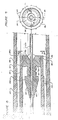
- the conventional practice for injecting medication into the body of the patient calls for a metal needle 10 to be removably attached to a syringe 12.
- This needle 10 has a plastic hub 14 with dog ears (not shown) that are threaded into a threaded delivery end 16 of the syringe.
- the needle 10 is ordinarily initially enclosed in a plastic sheath 18 which fits snugly about the hub 14. Needles 10 come in many different sizes, both in diameter and length, and they are enclosed individually within sheaths. The nurse selects which size needle to use in administering the medication and grasps the sheath 18 with one hand and then simply screws the needle 10 into position by inserting the hub 14 into the delivery end 16 of the syringe 12 and turning the sheath.
- the sheath 18 carries on its internal wall splines 18a which engage ribs 20 on the hub 14, enabling the sheath and needle to be rotated as a unit. With rotation, the dog ears slide into threads 16a in end 16 to lock the needle 10 on to the syringe 12.
- the nurse then pulls the sheath 18 off the hub 14, exposing the needle. She then inserts the needle 10 into the body of the patient, depresses a plunger (not shown) of the syringe 12 to force liquid medication through the needle, out of the needle tip 10a and into the patient and then pulls the needle from the patient. Normally the nurse will replace the sheath 18, inserting the needle 10 into the open mouth 18b of the sheath.
- the nurse is required by hospital protocols to clip the needle before she disposes of it. This is to prevent reuse of the needle 10.
- Such clipping of the needle 10 creates an aerosol which may contain infections microbes that could be enhaled by the nurse or others in the vicinity. This unsafe practice of clipping the needle and recovering it is not eliminated by the present invention.
- the medical device 22 of this invention includes a hub 14 having dog ears 14a (FIG. 7) at one end which allow the device 22 to be removably attached to the end of the syringe 12.
- Extending from this hub 14 is the elongated metal needle 10 of any desired length and thickness.
- Attached to the shaft 10a of the needle 10 is a movable guard 24 which moves axially along the shaft of the needle from a rearward position, as illustrated in FIG. 4, to a forward position, as illustrated in FIG. 5. In the forward position, the guard 24 is locked in place by means of a locking element 26 mounted to the shaft 10a of the needle 10.
- the guard 24 is in the retracted position and the sheath 18 encases both the needle 10 and the guard.
- the barrel hub 14 is molded from any suitable plastic and it has a sheath carrier forward section 14a.
- This section 14a preferably has a tapered side wall 14b which allows the barrel hub 15 to be inserted into the open mouth 18b of the sheath 18, with the inside wall of the sheath sitting snug against the side wall of section 14a to hold the cover in position.
- the barrel hub 14 has a generally cylindrical configuration and has a passageway 28 extending from the end of the hub connected to the syringe 12 to the end of the hub carrying the needle. This passageway 28 is centrally located along the longitudinal axis of the hub 14 and provides a conduit for the medication to flow from the syringe 12 into the needle 10.
- the hub 14 includes a fluid reservoir 30, with the passageway 28 having a series of parallel, bores 28a running about the passageway.
- the passageway 28 ends in a funnel-like open section 32.
- One end of the needle 10 is inserted into the passageway 28 and stops at the base of the reservoir 30.
- An adhesive 33 is inserted through the open section a 32 and flows around the outside wall of the needle shaft 10a and into the bores 28a filling them. On curing, the adhesive 33 bonds the needle 10 into position securely.
- the end of the barrel hub 14 opposite the reservoir 30 includes a cavity 34 with an open mouth 34a into which the rear of the guard 24 will pas.
- the cavity 34 is formed by an annular recess within the hub section 14a.
- a neck portion 14c Centrally located, and integral with the hub section 14a, is a neck portion 14c through which the passageway 28 extends. This neck portion 14c is of a generally cylindrical configuration.
- the guard 24 is a generally hollow cylindrical member made of plastic having at its rear end a collar member 40 in the form of a annular wall which is received within the cavity 34 when the guard is in the retracted position.
- the neck member 14c extends through an opening 40a in the collar 40, with the internal annular surface of the collar abutting the external surface of the neck 14c.
- the guard 24 has an open end 24a (FIG. 8) which is sufficiently restricted so that a typical adult user cannot insert his or her finger through this opening and contact the tip 10a of the needle 10.
- the diameter of this opening is less than one centimeter and the tip 10a of the needle is displaced inwardly from this opening a minimal distance of one-half centimeter.
- the rear end of the guard 24 has four equally spaced slits 42 extending lengthwise from the rear end to about the nipples 38. Each slit 42 terminates in a beveled end. These slits divide the collar 40 into four equal segments, which will flex outwardly, enlarging the opening 40a as the guard 24 engages the locking element 26. This feature will be explained in greater detail subsequently.
- a series of parallel ribs 44 molded in the exterior surface of the guard 24 to provide means for facilitating grasping and holding the guard.
- At the open end 24a of the guard 24 is an annular ridge 46 carried on the inside wall of the guard.
- This ridge has tapered side walls which are received in a corresponding tapered groove 48 in the locking element 26.
- the nipples 38 and ridge 46 hold the guard 24 in the rearward position until the nurse manually moves the guard forward to the position shown in FIG. 5. Thus there is enough play to allow the guard to be moved forward manually, but sufficient tightness so that the guard will not accidentally jar loose, for example, during shipment.
- the locking for the guard 24 is best illustrated by FIGS. 8 through 11.
- the locking element as shown in FIGS. 8 and 9 includes a body member 50 having a conical-like end portion 52 which provides a ramp over which the collar 40 rides as the guard is moved to the fully extended forward position. This ramp terminates in an annular rear shoulder 54.
- an annular front should 56 At the other end of the body member 50 is an annular front should 56.
- the front shoulder 56 is higher than the rear shoulder 54 and its diameter is just slightly less than the diameter of the open mouth 24a of the guard.
- a receptacle portion 58 which consists of an annular recess running about the central portion of the body member 50 having a base 58a and opposed inwardly tapered rear and front walls 58b and 58c.
- the collar 40 drops into this receptacle portion 58 when the guard 24 is moved to the fully extended forward position shown in FIG. 5.
- the collar segments spread apart slightly as the guard 24 moves up the ramp end 52.
- the opening 40a in the collar 40 expands slightly to allow this end 52 to pass through this opening with the collar riding up and over the shoulder 54.
- the opening 40a will resume its ordinary diameter and the collar 40 drops into the receptacle portion, with the front tapered wall 58c acting as a stop which abuts the collar.
- the tip 10a of the needle 10 is now exposed, as shown in FIG. 4.
- the nurse then penetrates the body of the patient, depresses the plunger of the syringe 18 to force medication through the passageway 28 and out of the tip 10a of the needle into the body of the patient.
- the nurse pulls the needle from the patient. Instead of placing the sheath back on the device 22, the nurse simply grasps an intermediate portion of the guard 24, which is in the position illustrated in FIG. 4, and pushes it forward in a smooth, one stroke motion. Even if the nurse's had slipped from the guard 24, her fingers would simply ride down the shaft 10b of the needle 10 and over the tip 10a of the needle, without sticking herself. This is contrary to the conventional practice where the nurse's hand moves in a direction towards the tip 10a of the needle 10.
- the nurse pushes the guard it will move to the right, as shown in FIG. 4, moving from the retracted position, as shown in FIG. 6, to the forward position, as shown in FIG. 5.
- the nipples 38 slips from the groove 36 and the ridge 46 slips from the groove 48.
- the shoulder 56 of the locking member provides stability and guidance for the guard 24 as it moves along the shaft 10b of the needle 10.
- the opening will once again close and the collar 40 will snap into the receptacle portion. Because of the tapered sidewalls of the walls of the receptacle portion and corresponding tappered walls of the collar the guard is locked into position. Thus, even if the nurse attempted to retract the guard by moving it to the position shown in FIG. 4, the collar 40, locked into position in the receptacle portion 58, will prevent the guard 24 from being returned to the retracted position. Thus, the guard 24 is permanently locked into position, protecting the nurse against accidental needle sticks. Because the guard 24 cannot be moved without destroying the entire structure of the device 22, and destroying the needle, it is not necessary to clip the needle. Thus a dangerous germ containing aerosol is not sprayed into the atmosphere.
Abstract
Description
- This invention relates to medical devices used with, for example, syringes and intravenous (IV) medication dispenser sets and, in particular, relates to a device for enclosing a needle after it has been used so that the needle will not accidentally stick the user.
- Many medications are administered by injecting the medication through a needle that has penetrated the body of the patient. The needle is usually removeably attached to a medication dispenser such as an IV set or syringe. When the needle is attached to a syringe, the nurse manually activates a plunger which forces the medication from the syringe through the needle, out the tip of the needle, into the body of the patient. It is common practice to use disposable needles. After the needle has been used, the nurse detaches the needle from the syringe and discards it. In many instances the nurse will clip the needle, rendering it unsuitable for subsequent use.
- The needles commonly employed are contained within a sheath made, for example, of plastic. This sheath grips the needle in a fashion that allows the nurse, while holding the sheath, to attach the needle to the delivery end of the syringe. Ordinarily a Luer lock, or other type of conventional threaded device, is employed which allows the nurse to simply screw the needle onto the delivery end of the syringe. With the needle attached to the syringe, the nurse removes the sheath, exposing the needle. After the needle has been used to inject medication into the patient, the nurse frequently will replace the sheath covering the needle. Ribs on the inside of the sheath engages splines on the barrel hub of the needle upon rotation. The nurse then rotates the sheath and to detatch the needle from the syringe. All too frequently in the act of resheathing the needle, the nurse accidentally sticks herself. If the patient is carrying a highly infectious disease, the nurse could be infected. Consequently, a blood test must be conducted on the nurse to see if she is already carrying the disease. This is necessary because if she is not infected at the time of the stick, her employer, the hospital, will be liable.
- Accidental needle sticks have been recognized as a serious health hazard and are discussed in U. S. patent application Serial No. 06/606,679, filed May 3, 1984, entitled Medical Connector, assigned to the same assignee as this patent application. This medical connector employs a needle housed within a cap member so that the nurse is protected against accidental needle sticks. This connector, however, is not suitable for directly administering medication to the patient through a needle which is inserted into the body of the patient. Others have suggested that a protective sheath for the needle be attached to the syringe and movable to cover the needle when the needle is not in use and then retracted to expose the needle. Such devices are illustrated in U. S. Patent Nos. 4,425,120 and 2,571,653, and 3,134,380, and 2,925,083. These devices, however, all contemplate repeated use of the needle. This would require resterilization after each use and is not consistent with current medical practices which employ disposable needles.
- The problems discussed above have been obviated by the present invention which provides a simple, safe, and convenient way to protect the user against needle sticks after the needle has been used to inject medication into a patient. There are several features of this invention, no single one of which is solely responsible for its desirable attributes. Without limiting the scope of this invention, as expressed by the claims, its more prominent features will now be discussed briefly. After considering this discussion, and particularly after reading the section of this application entitled "Detailed Description of the Preferred Embodiment," one will understand how the features of this invention provide the advantages of simplicity, convenience, and safety.
- One feature of the present invention is that the needle is covered with a guard after being used. The needle is secured to a connector which is adapted to be removably detached to the medication dispenser. This allows the needle to be detached and disposed after it is used. The guard is manually movable and mounted along the needle. It moves axially between a first position where the tip of the needle is exposed to a second position where the guard covers the tip of the needle and prevents needle sticks.
- In accordance with another feature of this invention, locking means are mounted along the needle which permanently locks the guard in the second position upon movement of the guard from the first position to the second position. Because the guard is locked in position, there is no chance that the nurse can be stuck with the needle after she uses it. The guard is a tubular element and it has a collar at its rearward end. Associated with the guard are means which releasably hold the guard in the first position so that the nurse may apply a minimum force to overcome the grip of the holding means. After using the needle, the nurse pushes the guard towards the tip of the needle to move it to the second position. The locking means includes a receptacle for the collar and a stop which limits the forward movement of the guard. When the guard has been moved forward, the collar engages the stop and snaps into locking position in the receptacle. In this position the tip of the needle is covered by the guard. The guard has an opening in its forward and rear end which allows the guard to move axially along the needle shaft. Thus the needle tip is exposed when the guard is in the first position, but permits the guard to be pulled over the tip upon forward movement of the guard. The opening at the forward end of the guard is restricted so that a nurse will not be able to stick his or her little finger through the opening and be pricked by the tip of the needle when the guard is in the second position.
- The medical device of this invention is made out of conventional plastic materials which are molded into the desired shapes, with the needle being conventional, made of a metal such as stainless steel. The device is easy to manufacture, is inexpensive, and most importantly, provides a safe way of protecting nurses against sticks from needles which have been used in administering medication to patients carrying highly infectious diseases. Once the needle has been used, the nurse simply moves the protective guard into position covering the needle, detaches the needle from the medication dispenser, and disposes of it by placing it in the suitable waste container. She does not need to clip the needle, because the guard is now permanently locked into position and one could only remove the guard by destroying the structure of the device.
- The preferred embodiment of this invention illustrating all its features will now be discussed in detail. This embodiment shows the device of this invention being used with a conventional syringe. It could be used in any application where it is desired to protect a needle after it has been inserted into a patient and it is no longer desired to reuse such needle.
- The medical device of this invention is illustrated in the drawing, with like numerals indicating like parts, and in which:
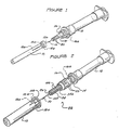
- FIG. 1 is an exploded perspective view of the conventional way of covering the disposable needle used with a syringe.
- FIG. 2 is an exploded perspective view of the medical device of this invention.
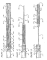
- FIG. 3 is a side elevational view, with sections broken away, of the medical device of this invention, with the sheath for the device in position and the guard for the needle in a retracted position.
- FIG. 4 is a side elevational view of the device shown in FIG. 3, with the sheath removed.
- FIG. 5 is a side-elevational view of the device shown in FIG. 4, with the guard moved to a forward position to cover the tip of the needle.
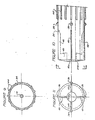
- FIG. 6 is a cross-sectional view taken along line 6-6 of FIG. 5.
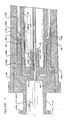
- FIG. 7 is an enlarged fragmentary view, in cross-section, of the rear end of the device of this invention, with the guard in the retracted position.
- FIG. 8 is an enlarged fragmentary view in cross-section of an intermittent portion of the device, with the guard in the retracted position.
- FIG. 9 is a cross-sectional view taken along line 9-9 of FIG. 8.
- FIG. 10 is an enlarged fragmentary view of the rear end of the guard.
- FIG. 11 is a cross-sectional view taken along line 11-11 of FIG. 10.
- As illustrated in FIG. 1, the conventional practice for injecting medication into the body of the patient calls for a
metal needle 10 to be removably attached to asyringe 12. Thisneedle 10 has aplastic hub 14 with dog ears (not shown) that are threaded into a threadeddelivery end 16 of the syringe. Theneedle 10 is ordinarily initially enclosed in aplastic sheath 18 which fits snugly about thehub 14.Needles 10 come in many different sizes, both in diameter and length, and they are enclosed individually within sheaths. The nurse selects which size needle to use in administering the medication and grasps thesheath 18 with one hand and then simply screws theneedle 10 into position by inserting thehub 14 into thedelivery end 16 of thesyringe 12 and turning the sheath. Thesheath 18 carries on its internal wall splines 18a which engageribs 20 on thehub 14, enabling the sheath and needle to be rotated as a unit. With rotation, the dog ears slide into threads 16a inend 16 to lock theneedle 10 on to thesyringe 12. The nurse then pulls thesheath 18 off thehub 14, exposing the needle. She then inserts theneedle 10 into the body of the patient, depresses a plunger (not shown) of thesyringe 12 to force liquid medication through the needle, out of the needle tip 10a and into the patient and then pulls the needle from the patient. Normally the nurse will replace thesheath 18, inserting theneedle 10 into the open mouth 18b of the sheath. It is at this point that accidents commonly occur. If the nurse is distracted, has poor eyesight, or is simply inattentive, she may stick herself with theneedle 10. If theneedle 10 has just been used to inject medication into a patient infected with a highly contageous disease, it is likely that the nurse will contract the disease if she accidentally sticks herself with the needle. If she does manage to replace thesheath 18 on theneedle 10 without sticking herself, she then detaches theneedle 10 by turning the sheath with the hub14 of the needle inserted snugly into open mouth 18b of thesheath 18. Rotation then occurs between theneedle hub 14 and thedelivery end 16 of thesyringe 18 to detach theneedle 10 from the syringe. In many instances, the nurse is required by hospital protocols to clip the needle before she disposes of it. This is to prevent reuse of theneedle 10. Such clipping of theneedle 10 creates an aerosol which may contain infections microbes that could be enhaled by the nurse or others in the vicinity. This unsafe practice of clipping the needle and recovering it is not eliminated by the present invention. - As illustrated in FIG. 2, the
medical device 22 of this invention includes ahub 14 having dog ears 14a (FIG. 7) at one end which allow thedevice 22 to be removably attached to the end of thesyringe 12. Extending from thishub 14 is theelongated metal needle 10 of any desired length and thickness. Attached to the shaft 10a of theneedle 10 is amovable guard 24 which moves axially along the shaft of the needle from a rearward position, as illustrated in FIG. 4, to a forward position, as illustrated in FIG. 5. In the forward position, theguard 24 is locked in place by means of a lockingelement 26 mounted to the shaft 10a of theneedle 10. As best illustrated in FIG. 3, prior to use, theguard 24 is in the retracted position and thesheath 18 encases both theneedle 10 and the guard. - As best shown in FIG. 7, the
barrel hub 14 is molded from any suitable plastic and it has a sheath carrier forward section 14a. This section 14a preferably has a tapered side wall 14b which allows the barrel hub 15 to be inserted into the open mouth 18b of thesheath 18, with the inside wall of the sheath sitting snug against the side wall of section 14a to hold the cover in position. Thebarrel hub 14 has a generally cylindrical configuration and has apassageway 28 extending from the end of the hub connected to thesyringe 12 to the end of the hub carrying the needle. Thispassageway 28 is centrally located along the longitudinal axis of thehub 14 and provides a conduit for the medication to flow from thesyringe 12 into theneedle 10. - The
hub 14 includes a fluid reservoir 30, with thepassageway 28 having a series of parallel, bores 28a running about the passageway. Thepassageway 28 ends in a funnel-likeopen section 32. One end of theneedle 10 is inserted into thepassageway 28 and stops at the base of the reservoir 30. An adhesive 33 is inserted through the open section a 32 and flows around the outside wall of the needle shaft 10a and into the bores 28a filling them. On curing, the adhesive 33 bonds theneedle 10 into position securely. - The end of the
barrel hub 14 opposite the reservoir 30 includes acavity 34 with an open mouth 34a into which the rear of theguard 24 will pas. Thecavity 34 is formed by an annular recess within the hub section 14a. There is formed by an annular recess within the hub section 14a. There is acircumferential groove 36 adjacent themouth 34 which engages a row of spaced nipples 38 (FIG. 10) carried on the exterior of the rear end of theguard 24. Centrally located, and integral with the hub section 14a, is aneck portion 14c through which thepassageway 28 extends. Thisneck portion 14c is of a generally cylindrical configuration. - The
guard 24 is a generally hollow cylindrical member made of plastic having at its rear end acollar member 40 in the form of a annular wall which is received within thecavity 34 when the guard is in the retracted position. Theneck member 14c extends through an opening 40a in thecollar 40, with the internal annular surface of the collar abutting the external surface of theneck 14c. Theguard 24 has anopen end 24a (FIG. 8) which is sufficiently restricted so that a typical adult user cannot insert his or her finger through this opening and contact the tip 10a of theneedle 10. Typically the diameter of this opening is less than one centimeter and the tip 10a of the needle is displaced inwardly from this opening a minimal distance of one-half centimeter. - As best illsutrated in FIGS. 10 and 11, the rear end of the
guard 24 has four equally spacedslits 42 extending lengthwise from the rear end to about thenipples 38. Each slit 42 terminates in a beveled end. These slits divide thecollar 40 into four equal segments, which will flex outwardly, enlarging the opening 40a as theguard 24 engages the lockingelement 26. This feature will be explained in greater detail subsequently. A series ofparallel ribs 44 molded in the exterior surface of theguard 24 to provide means for facilitating grasping and holding the guard. At theopen end 24a of theguard 24 is an annular ridge 46 carried on the inside wall of the guard. This ridge has tapered side walls which are received in a corresponding taperedgroove 48 in the lockingelement 26. Thenipples 38 and ridge 46 hold theguard 24 in the rearward position until the nurse manually moves the guard forward to the position shown in FIG. 5. Thus there is enough play to allow the guard to be moved forward manually, but sufficient tightness so that the guard will not accidentally jar loose, for example, during shipment. - The locking for the
guard 24 is best illustrated by FIGS. 8 through 11. The locking element as shown in FIGS. 8 and 9 includes abody member 50 having a conical-like end portion 52 which provides a ramp over which thecollar 40 rides as the guard is moved to the fully extended forward position. This ramp terminates in an annularrear shoulder 54. At the other end of thebody member 50 is an annular front should 56. Thefront shoulder 56 is higher than therear shoulder 54 and its diameter is just slightly less than the diameter of theopen mouth 24a of the guard. Between theshoulders receptacle portion 58 which consists of an annular recess running about the central portion of thebody member 50 having a base 58a and opposed inwardly tapered rear and front walls 58b and 58c. Thecollar 40 drops into thisreceptacle portion 58 when theguard 24 is moved to the fully extended forward position shown in FIG. 5. The collar segments spread apart slightly as theguard 24 moves up the ramp end 52. Thus, the opening 40a in thecollar 40 expands slightly to allow this end 52 to pass through this opening with the collar riding up and over theshoulder 54. When thecollar 40 is opposite thereceptacle portion 58, the opening 40a will resume its ordinary diameter and thecollar 40 drops into the receptacle portion, with the front tapered wall 58c acting as a stop which abuts the collar. Once thecollar 40 is in thereceptacle portion 58, the guard is permanently locked into position so that it cannot move rearwardly to return to the position shown in FIG. 4. - To use of the medical device of this invention, one would first attach it to the
delivery end 16 of thesyringe 12, as shown in FIG. 3, inserting the dog ears 14a into the threads 16a in delivery end of the syringe and turning thedevice 22 to screw it in position. The nurse would then removesheath 18 by simply pulling it off thebarrel hub 14. - The tip 10a of the
needle 10 is now exposed, as shown in FIG. 4. The nurse then penetrates the body of the patient, depresses the plunger of thesyringe 18 to force medication through thepassageway 28 and out of the tip 10a of the needle into the body of the patient. After the medication has been administered to the patient, the nurse pulls the needle from the patient. Instead of placing the sheath back on thedevice 22, the nurse simply grasps an intermediate portion of theguard 24, which is in the position illustrated in FIG. 4, and pushes it forward in a smooth, one stroke motion. Even if the nurse's had slipped from theguard 24, her fingers would simply ride down the shaft 10b of theneedle 10 and over the tip 10a of the needle, without sticking herself. This is contrary to the conventional practice where the nurse's hand moves in a direction towards the tip 10a of theneedle 10. - As the nurse pushes the guard, it will move to the right, as shown in FIG. 4, moving from the retracted position, as shown in FIG. 6, to the forward position, as shown in FIG. 5. When the nurse initiates this movement of the
guard 24, thenipples 38 slips from thegroove 36 and the ridge 46 slips from thegroove 48. Theshoulder 56 of the locking member provides stability and guidance for theguard 24 as it moves along the shaft 10b of theneedle 10. When the collar engages the ramp end 52, the tip of the ramp end is inserted into the opening 40a, spreading the collar apart, slightly enlarging this opening 40a as the collar rides up the ramp and over therear shoulder 54. When thecollar 40 is opposite thereceptacle portion 58, the opening will once again close and thecollar 40 will snap into the receptacle portion. Because of the tapered sidewalls of the walls of the receptacle portion and corresponding tappered walls of the collar the guard is locked into position. Thus, even if the nurse attempted to retract the guard by moving it to the position shown in FIG. 4, thecollar 40, locked into position in thereceptacle portion 58, will prevent theguard 24 from being returned to the retracted position. Thus, theguard 24 is permanently locked into position, protecting the nurse against accidental needle sticks. Because theguard 24 cannot be moved without destroying the entire structure of thedevice 22, and destroying the needle, it is not necessary to clip the needle. Thus a dangerous germ containing aerosol is not sprayed into the atmosphere. - The above description presents the best mode contemplated upon carrying out the present invention. This invention is, however, susceptable to modification and alternate constructions from the embodiments shown in the drawing and described above. Conseqeuently, it is not the intention to limit this invention to the particular embodiments disclosed. On the contrary, the intention is to cover all modifications and alternate constructions coming within the spirit and scope of the invention as expressed by the claims.
Claims (20)
connector means which is adapted to be removably attached to the syringe;
an elongated needle having a tip and a rear end secured to the connector means, said needle being in communication with the dispenser upon attachment of the connector means to the syringe so that the medication contained within the syringe will flow from the syringe through the needle and out said tip;
manually movable guard means mounted along the needle to move between a first position with the guard means rearwardly from the tip so that the tip of the needle is exposed and a second position where the guard means covers said tip to prevent needle sticks, and
locking means mounted along said needle which permanently locks the guard means in the second position upon movement of the guard means from the first position to the second position.
a metal needle having one end adapted to be placed in communication with a source of medication, a hollow shaft through which the medication flows, and an open tip adapted to penetrate the body of the patient and from which the medication exits the needle;
a guard member mounted on the shaft of the needle and movable axially along the shaft between a first position where the guard means is displaced inwardly from the tip to expose said tip to enable it to penetrate the body of a patient and a second position where the sheath member covers said tip to prevent needle sticks; and
locking means mounted along said needle shaft which permanently locks the guard member in the second position upon movement of said guard member from the first position to the second position.
connector means having a hub portion with a first end having means for removably attaching the connector means to the dispenser and a second end disposed to the first end, said hub portion having a passageway therein extending between the first and second ends through which medication dispensed by the dispenser may flow;
a metal needle secured to the second end of the barrel portion and in communication with the passageway, said needle having an elongated hollow shaft through which the medication flows and at the end of the shaft an open tip adapted to penetrate the body of a patient and from which the medication exits the needle;
an elongated tubular guard mounted on the shaft of the needle and movable axially along the shaft between a first position where the guard is displaced inwardly from the tip of the needle to enable the needle to penetrate the body of a patient and a second position where the guard covers the needle tip to prevent needle sticks;
said guard having at its rearward end a collar member and at its forward end a restricted opening, with said needle extending through the restricted opening when guard is in the first position to expose said tip and being displaced inwardly from said opening when the guard is in the second position, said opening being sufficiently restricted so that the tip of the little finger of a typical adult user cannot be inserted into the opening and thereby stuck by the tip of the needle;
locking means mounted along the shaft of the needle between the needle tip and the second end of the hub portion which permanently locks the guard in the second position upon movement of the sheath from the first position to the second position, said locking means including a shoulder element which serves to support guard when said guard is in the first position, act as a guide as the guard moves from the first position to the second position and acts as a stop to prevent further axial movement of the guard when it reaches the second position.
Applications Claiming Priority (2)
| Application Number | Priority Date | Filing Date | Title |
|---|---|---|---|
| US849148 | 1986-04-07 | ||
| US06/849,148 US4778453A (en) | 1986-04-07 | 1986-04-07 | Medical device |
Publications (3)
| Publication Number | Publication Date |
|---|---|
| EP0240987A2 true EP0240987A2 (en) | 1987-10-14 |
| EP0240987A3 EP0240987A3 (en) | 1988-10-05 |
| EP0240987B1 EP0240987B1 (en) | 1992-12-16 |
Family
ID=25305177
Family Applications (1)
| Application Number | Title | Priority Date | Filing Date |
|---|---|---|---|
| EP87105129A Expired - Lifetime EP0240987B1 (en) | 1986-04-07 | 1987-04-07 | Medical device |
Country Status (6)
| Country | Link |
|---|---|
| US (1) | US4778453A (en) |
| EP (1) | EP0240987B1 (en) |
| KR (1) | KR900000257B1 (en) |
| CA (1) | CA1290212C (en) |
| DE (1) | DE3783068T2 (en) |
| ES (1) | ES2037022T3 (en) |
Cited By (11)
| Publication number | Priority date | Publication date | Assignee | Title |
|---|---|---|---|---|
| EP0286992A2 (en) * | 1987-04-13 | 1988-10-19 | ICU MEDICAL, INC. (a California corporation) | Medical device |
| US4994045A (en) * | 1990-04-20 | 1991-02-19 | Sherwood Medical Company | Split sleeve safety syringe |
| US4998924A (en) * | 1989-07-25 | 1991-03-12 | Sherwood Medical Company | Double sleeve safety syringe |
| US5053018A (en) * | 1988-06-28 | 1991-10-01 | Sherwood Medical Company | Combined syringe and needle shield and method of manufacture |
| US5156599A (en) * | 1988-06-28 | 1992-10-20 | Sherwood Medical Company | Syringe and sliding locking needle shield |
| US5195992A (en) * | 1988-05-13 | 1993-03-23 | Baxter International Inc. | Protector shield for needles |
| WO1994003224A1 (en) * | 1992-07-31 | 1994-02-17 | Luckhurst, Anthony, Henry, William | Needle protective device |
| US5685866A (en) * | 1991-12-18 | 1997-11-11 | Icu Medical, Inc. | Medical valve and method of use |
| US5694686A (en) * | 1991-12-18 | 1997-12-09 | Icu Medical, Inc. | Method for assembling a medical valve |
| US5810792A (en) * | 1996-04-03 | 1998-09-22 | Icu Medical, Inc. | Locking blunt cannula |
| US7947032B2 (en) | 2001-12-07 | 2011-05-24 | Becton, Dickinson And Company | Needleless luer access connector |
Families Citing this family (123)
| Publication number | Priority date | Publication date | Assignee | Title |
|---|---|---|---|---|
| US4943284A (en) * | 1987-03-09 | 1990-07-24 | Erlich Frederick L | Sheath for devices for injecting or withdrawing body fluids |
| US4878902A (en) * | 1988-02-25 | 1989-11-07 | Wanderer Alan A | Needle guard for body substance isolation |
| US4935012A (en) * | 1988-06-10 | 1990-06-19 | George R. Magre | Safety device for medical needles |
| US4927415A (en) * | 1988-08-12 | 1990-05-22 | Brodsky Stuart A | Apparatus for safe use and disposal of needles |
| US5267975A (en) * | 1988-08-12 | 1993-12-07 | Brodsky Stuart A | Apparatus for safe use, disposal and retention of needles |
| CA1315166C (en) * | 1988-10-05 | 1993-03-30 | John S. Parry | Injection devices |
| US4955866A (en) * | 1988-10-19 | 1990-09-11 | University Of Florida | Hypodermic needle recapping device |
| US5322517A (en) * | 1989-02-01 | 1994-06-21 | Sero-Guard Corporation | Disposable automatic hypodermic needle guard |
| US5843041A (en) * | 1989-03-02 | 1998-12-01 | Hake; Lawrence W. | Hypodermic needle guard and method to prevent needle stick injuries |
| US5314414A (en) * | 1989-03-02 | 1994-05-24 | Needlepoint Guard, Inc. | Hypodermic needle guard and method to prevent needle stick injuries |
| US6017329A (en) * | 1989-03-02 | 2000-01-25 | Hake; Lawrence W. | Hypodermic needle guard and method to prevent needle stick injuries |
| US5141500A (en) * | 1989-03-02 | 1992-08-25 | Lawrence W. Hake | Hypodermic needle guard |
| US5256153A (en) * | 1989-03-02 | 1993-10-26 | Hake Lawrence W | Hypodermic needle guard and method to prevent needle stick injuries |
| US5019051A (en) * | 1989-03-02 | 1991-05-28 | Needlepoint Guard, Inc. | Hypodermic needle guard |
| US4976699A (en) * | 1989-05-24 | 1990-12-11 | Gold Steven K | Needle and safety cover assembly for syringes and the like |
| BR8904934A (en) * | 1989-09-28 | 1991-04-02 | Adrian Brizuela Ricardo | PROTECTIVE DEVICE FOR GUIDE PIPES USED WITH BLOOD AND SERUM AND SIMILAR BAGS |
| US4998920A (en) * | 1989-10-11 | 1991-03-12 | Delores Johnson | Protective assembly for hypodermic syringe devices |
| US5026345A (en) * | 1990-04-18 | 1991-06-25 | William Teringo | Non-mechanical incapacitation syringe safety needle guard |
| US4982842A (en) * | 1990-06-04 | 1991-01-08 | Concord/Portex | Safety needle container |
| US5232454A (en) * | 1990-08-01 | 1993-08-03 | Smiths Industries Medical Systems, Inc. | Safety needle container |
| US5139489A (en) * | 1991-01-07 | 1992-08-18 | Smiths Industries Medical Systems, Inc. | Needle protection device |
| US5176655A (en) * | 1990-11-08 | 1993-01-05 | Mbo Laboratories, Inc. | Disposable medical needle and catheter placement assembly having full safety enclosure means |
| US5232455A (en) * | 1991-01-07 | 1993-08-03 | Smiths Industries Medical Systems, Inc. | Syringe with protective housing |
| DE69215981T2 (en) * | 1991-01-14 | 1997-05-15 | Precision Dynamics Corp | CANNULA PROTECTION |
| US5215528C1 (en) * | 1992-02-07 | 2001-09-11 | Becton Dickinson Co | Catheter introducer assembly including needle tip shield |
| WO1993017735A1 (en) * | 1992-03-10 | 1993-09-16 | Injectimed, Inc. | Unitary injection apparatus incorporating retractable sleeve needle protection apparatus |
| JP3854308B2 (en) | 1992-05-18 | 2006-12-06 | スミスズ メディカル エイエスディー インコーポレイテッド | Safety needle protection device |
| US5250036A (en) * | 1992-11-24 | 1993-10-05 | Mohammad Farivar | Intravenous catheter placement system |
| US5795336A (en) * | 1993-02-11 | 1998-08-18 | Beech Medical Products, Inc. | Automatic needle protector having features for facilitating assembly |
| US5993426A (en) | 1993-04-16 | 1999-11-30 | Sims Portex Inc. | Fluid absorbable needle sheath |
| CA2127206A1 (en) * | 1993-07-23 | 1995-01-24 | Charles W. Daugherty | Self contained needle and shield |
| US5338311A (en) * | 1993-08-23 | 1994-08-16 | Mahurkar Sakharam D | Hypodermic needle assembly |
| US6280401B1 (en) | 1993-08-23 | 2001-08-28 | Sakharam D. Mahurkar | Hypodermic needle assembly |
| US5836921A (en) * | 1993-08-23 | 1998-11-17 | Mahurkar; Sakharam D. | Hypodermic needle assembly |
| US5419766A (en) * | 1993-09-28 | 1995-05-30 | Critikon, Inc. | Catheter with stick protection |
| US5403283A (en) * | 1993-10-28 | 1995-04-04 | Luther Medical Products, Inc. | Percutaneous port catheter assembly and method of use |
| KR100441231B1 (en) | 1994-06-24 | 2004-10-12 | 아이시유메디칼인코오포레이티드 | Fluid transfer device and method of use |
| GB2292525B (en) * | 1994-08-24 | 1998-07-01 | Sterimatic Holdings Ltd | Catheter placement units |
| US5769827A (en) * | 1994-08-25 | 1998-06-23 | Safeguard Needle International, Inc. | Safety needle apparatus and method |
| US7300416B2 (en) * | 1995-08-22 | 2007-11-27 | Specialized Health Products International | Pre-filled retractable needle injection ampoules |
| US5738663A (en) | 1995-12-15 | 1998-04-14 | Icu Medical, Inc. | Medical valve with fluid escape space |
| US5873864A (en) * | 1995-12-18 | 1999-02-23 | Luther Medical Products, Inc. | Catheter with beveled needle tip |
| US5743882A (en) * | 1996-03-08 | 1998-04-28 | Luther Medical Products, Inc. | Needle blunting assembly for use with intravascular introducers |
| US5817060A (en) * | 1996-03-08 | 1998-10-06 | Luther Medical Products, Inc. | Unidirectional blunting apparatus for hypodermic needles |
| US5913848A (en) | 1996-06-06 | 1999-06-22 | Luther Medical Products, Inc. | Hard tip over-the-needle catheter and method of manufacturing the same |
| US5957898A (en) | 1997-05-20 | 1999-09-28 | Baxter International Inc. | Needleless connector |
| ATE335518T1 (en) | 1997-05-20 | 2006-09-15 | Baxter Int | NEEDLELESS COUPLING PIECE |
| US6569115B1 (en) * | 1997-08-28 | 2003-05-27 | Mdc Investment Holdings, Inc. | Pre-filled retractable needle injection device |
| US6117112A (en) * | 1997-11-18 | 2000-09-12 | Mahurkar; Sakharam D. | Single-use safety syringe |
| US6019750A (en) | 1997-12-04 | 2000-02-01 | Baxter International Inc. | Sliding reconstitution device with seal |
| US7223258B2 (en) | 1998-08-28 | 2007-05-29 | Becton Dickinson And Company | Safety shield assembly |
| US7425209B2 (en) | 1998-09-15 | 2008-09-16 | Baxter International Inc. | Sliding reconstitution device for a diluent container |
| AR021220A1 (en) | 1998-09-15 | 2002-07-03 | Baxter Int | CONNECTION DEVICE FOR ESTABLISHING A FLUID COMMUNICATION BETWEEN A FIRST CONTAINER AND A SECOND CONTAINER. |
| US6113583A (en) | 1998-09-15 | 2000-09-05 | Baxter International Inc. | Vial connecting device for a sliding reconstitution device for a diluent container |
| US6146337A (en) * | 1998-11-25 | 2000-11-14 | Bio-Plexus, Inc. | Holder for blood collection needle with blunting mechanism |
| US6733465B1 (en) | 1998-11-25 | 2004-05-11 | Bio-Plexus, Inc. | Holder for blood collection needle with blunting mechanism |
| US6780169B2 (en) | 1999-08-23 | 2004-08-24 | Becton, Dickinson And Company | Safety shield assembly |
| US6699217B2 (en) | 1999-08-23 | 2004-03-02 | Becton, Dickinson And Company | Safety needle assembly |
| US6648855B2 (en) | 1999-08-23 | 2003-11-18 | Becton, Dickinson And Company | Safety needle assembly |
| US6494865B1 (en) * | 1999-10-14 | 2002-12-17 | Becton Dickinson And Company | Intradermal delivery device including a needle assembly |
| US7198618B2 (en) | 1999-11-04 | 2007-04-03 | Tyco Healthcare Group Lp | Safety shield for medical needles |
| US6592556B1 (en) | 2000-07-19 | 2003-07-15 | Tyco Healthcare Group Lp | Medical needle safety apparatus and methods |
| US8226617B2 (en) | 1999-11-04 | 2012-07-24 | Tyco Healthcare Group Lp | Safety shield apparatus and mounting structure for use with medical needle devices |
| US6280420B1 (en) | 1999-11-04 | 2001-08-28 | Specialized Health Products | Reaccessible medical needle safety devices and methods |
| US7029461B2 (en) | 1999-11-04 | 2006-04-18 | Tyco Healthcare Group Lp | Safety shield for medical needles |
| AU1530201A (en) | 1999-11-18 | 2001-05-30 | Scientific Generics Limited | Safety device |
| US6695817B1 (en) | 2000-07-11 | 2004-02-24 | Icu Medical, Inc. | Medical valve with positive flow characteristics |
| US7361159B2 (en) | 2001-03-02 | 2008-04-22 | Covidien Ag | Passive safety shield |
| US7144389B2 (en) | 2001-03-14 | 2006-12-05 | Tyco Healthcare Group, Lp | Safety shield for medical needles |
| EP1401514B1 (en) | 2001-05-22 | 2008-10-22 | Becton, Dickinson and Company | Needle shield assembly having hinged needle shield |
| US7220249B2 (en) | 2001-06-06 | 2007-05-22 | Becton, Dickinson And Company | Hinged needle shield assembly having needle cannula lock |
| AU2002354638B2 (en) | 2001-07-09 | 2009-01-22 | Becton, Dickinson And Company | Needle shield assembly having hinged needle shield and flexible cannula lock |
| US20040030294A1 (en) | 2001-11-28 | 2004-02-12 | Mahurkar Sakharam D. | Retractable needle single use safety syringe |
| US7001363B2 (en) | 2002-04-05 | 2006-02-21 | F. Mark Ferguson | Safety shield for medical needles |
| SG121744A1 (en) | 2002-11-06 | 2006-05-26 | Becton Dickinson Co | Flashback blood collection needle with needle shield |
| GB2398248A (en) | 2003-02-14 | 2004-08-18 | Scient Generics Ltd | Safety device with trigger mechanism |
| US7553296B2 (en) | 2003-02-14 | 2009-06-30 | Tyco Healthcare Group Lp | Safety device with trigger mechanism |
| CA2529429C (en) | 2003-06-17 | 2009-10-20 | Filtertek Inc. | Fluid handling device and method of making same |
| GB0327136D0 (en) * | 2003-11-21 | 2003-12-24 | Nmt Group Plc | Safety needle |
| US7641851B2 (en) | 2003-12-23 | 2010-01-05 | Baxter International Inc. | Method and apparatus for validation of sterilization process |
| US20060100576A1 (en) * | 2004-08-03 | 2006-05-11 | Tung-Hua Wang | Safety device of syringe needle |
| EP1796539B1 (en) * | 2004-08-16 | 2011-03-16 | Becton, Dickinson and Company | Flashback blood collection needle |
| US20060161115A1 (en) | 2004-11-05 | 2006-07-20 | Fangrow Thomas F | Soft-grip medical connector |
| JP4920673B2 (en) * | 2005-03-07 | 2012-04-18 | アースキン メディカル エルエルシー | Winged needle with needle shield |
| US8162881B2 (en) * | 2005-08-08 | 2012-04-24 | Smiths Medical Asd, Inc. | Needle guard mechanism with angled strut wall |
| US7753877B2 (en) * | 2005-08-08 | 2010-07-13 | Smiths Medical Asd, Inc. | Needle guard strut wall clip |
| US7632243B2 (en) * | 2005-08-08 | 2009-12-15 | Smiths Medical Asd, Inc. | Duckbill catheter release mechanism |
| US8403886B2 (en) * | 2005-08-08 | 2013-03-26 | Smiths Medical Asd, Inc. | Needle guard clip with lip |
| US7658725B2 (en) * | 2006-02-16 | 2010-02-09 | Smiths Medical Asd, Inc. | Enclosed needle device with duckbill release mechanism |
| US8496627B2 (en) | 2006-03-21 | 2013-07-30 | Covidien Lp | Passive latch ring safety shield for injection devices |
| GB2437923B (en) * | 2006-05-11 | 2011-11-23 | Owen Mumford Ltd | Needle tip storage and removal device |
| JP4994775B2 (en) | 2006-10-12 | 2012-08-08 | 日本コヴィディエン株式会社 | Needle point protector |
| BRPI0717401A2 (en) | 2006-10-25 | 2013-11-12 | Icu Medical Inc | CONNECTOR FOR MEDICAL USE |
| US8057431B2 (en) | 2006-12-21 | 2011-11-15 | B. Braun Melsungen Ag | Hinged cap for needle device |
| US8038654B2 (en) | 2007-02-26 | 2011-10-18 | Becton, Dickinson And Company | Syringe having a hinged needle shield |
| EP2139544A4 (en) * | 2007-04-26 | 2014-02-19 | Covidien Lp | Multifunctional medical access device |
| AU2008326336B2 (en) | 2007-11-21 | 2013-11-28 | Becton, Dickinson And Company | Safety needle guard |
| NZ585519A (en) | 2007-11-21 | 2012-10-26 | Becton Dickinson Co | A needle guard with a pivoting arm with a needle tip sensing element |
| US7785296B2 (en) * | 2008-07-17 | 2010-08-31 | Smiths Medical Asd, Inc. | Needle tip spring protector |
| US8454579B2 (en) | 2009-03-25 | 2013-06-04 | Icu Medical, Inc. | Medical connector with automatic valves and volume regulator |
| US7918821B2 (en) | 2009-05-05 | 2011-04-05 | Mahurkar Sakharam D | Universal safety syringe |
| USD644731S1 (en) | 2010-03-23 | 2011-09-06 | Icu Medical, Inc. | Medical connector |
| JP5836931B2 (en) | 2010-03-26 | 2015-12-24 | テルモ株式会社 | Indwelling needle assembly |
| SG184479A1 (en) | 2010-04-05 | 2012-11-29 | Py Daniel C | Aseptic connector with deflectable ring of concern and method |
| US8758306B2 (en) | 2010-05-17 | 2014-06-24 | Icu Medical, Inc. | Medical connectors and methods of use |
| CN103354754B (en) | 2010-12-02 | 2016-02-24 | 厄斯金医学有限公司 | For the relieving mechanism used together with pin masking device |
| WO2012075402A1 (en) | 2010-12-02 | 2012-06-07 | Erskine Medical Llc | Needle shield assembly with hub engagement member for needle device |
| CA2828741C (en) | 2011-04-07 | 2016-06-07 | Erskine Medical Llc | Needle shielding device |
| US8486024B2 (en) | 2011-04-27 | 2013-07-16 | Covidien Lp | Safety IV catheter assemblies |
| EP2760521B1 (en) | 2011-09-26 | 2016-01-06 | Covidien LP | Safety iv catheter and needle assembly |
| WO2013048975A1 (en) | 2011-09-26 | 2013-04-04 | Covidien Lp | Safety catheter |
| US8834422B2 (en) | 2011-10-14 | 2014-09-16 | Covidien Lp | Vascular access assembly and safety device |
| GB2497735A (en) | 2011-12-16 | 2013-06-26 | Owen Mumford Ltd | Needle Tip Storage and Removal Device |
| US9951899B2 (en) | 2012-04-17 | 2018-04-24 | Dr. Py Institute, Llc | Self closing connector |
| WO2013166143A1 (en) | 2012-05-01 | 2013-11-07 | Py Daniel C | Device for connecting or filling and method |
| US10351271B2 (en) | 2012-05-01 | 2019-07-16 | Dr. Py Institute Llc | Device for connecting or filling and method |
| EP3079739B1 (en) | 2013-12-11 | 2023-02-22 | ICU Medical, Inc. | Check valve |
| US20150238697A1 (en) * | 2014-01-25 | 2015-08-27 | Andersen-Michaud, Llc | Syringes Having Tactile Labeling Elements |
| US9555221B2 (en) | 2014-04-10 | 2017-01-31 | Smiths Medical Asd, Inc. | Constant force hold tip protector for a safety catheter |
| USD786427S1 (en) | 2014-12-03 | 2017-05-09 | Icu Medical, Inc. | Fluid manifold |
| USD793551S1 (en) | 2014-12-03 | 2017-08-01 | Icu Medical, Inc. | Fluid manifold |
| JP6794349B2 (en) | 2015-05-15 | 2020-12-02 | テルモ株式会社 | Catheter assembly |
| EP3405231A4 (en) | 2016-01-19 | 2019-10-16 | Daniel Py | Single use connectors |
Citations (6)
| Publication number | Priority date | Publication date | Assignee | Title |
|---|---|---|---|---|
| US2571653A (en) * | 1950-02-25 | 1951-10-16 | Bastien Victor Gerard | Syringe |
| US2876770A (en) * | 1955-10-10 | 1959-03-10 | Raymond A White | Shielded hypodermic syringe |
| US2925083A (en) * | 1957-12-27 | 1960-02-16 | Clarence D Craig | Hypodermic syringe with hood for guarding and concealing the needle |
| US3134380A (en) * | 1962-02-08 | 1964-05-26 | Thomas A Armao | Shielded hypodermic needle |
| US4425120A (en) * | 1982-04-15 | 1984-01-10 | Sampson Norma A | Shielded hypodermic syringe |
| US4430082A (en) * | 1982-06-25 | 1984-02-07 | Hoffmann-La Roche Inc. | Hypodermic syringe assembly |
Family Cites Families (16)
| Publication number | Priority date | Publication date | Assignee | Title |
|---|---|---|---|---|
| CA689751A (en) * | 1964-06-30 | M. Roehr Zbislaw | Ejector package | |
| US268996A (en) * | 1882-12-12 | Xhypodermic n needle | ||
| US3380448A (en) * | 1964-11-24 | 1968-04-30 | Abbott Lab | Cervical-pudendal indwelling catheter set with tissue piercing means |
| FR1541417A (en) * | 1966-06-21 | 1968-10-04 | Disposable syringe after use | |
| US3406687A (en) * | 1966-06-23 | 1968-10-22 | Resiflex Lab | Guide and positioning means for a needle |
| US3658061A (en) * | 1970-11-10 | 1972-04-25 | Baxter Laboratories Inc | Needle guard |
| US3890971A (en) * | 1973-10-23 | 1975-06-24 | Thomas A Leeson | Safety syringe |
| US3943927A (en) * | 1975-03-03 | 1976-03-16 | Norgren Robert S | Injection apparatus |
| US4026287A (en) * | 1975-12-10 | 1977-05-31 | Irene Haller | Syringe with retractable cannula |
| US4170993A (en) * | 1978-03-13 | 1979-10-16 | Marcial Alvarez | Sliding I.V. needle carrier assembly |
| DE2929425A1 (en) * | 1979-07-20 | 1981-02-12 | Lothar Kling | DEVICE FOR INJECTION SYRINGES FOR INTRAMUSCULAR AND SUBENTANE INJECTION |
| US4329989A (en) * | 1981-02-23 | 1982-05-18 | Edsyn, Inc. | Liquid dispenser |
| FR2539302B1 (en) * | 1983-01-17 | 1986-03-14 | Brunet Jean Louis | SYRINGE FOR MEDICAL USE |
| US4610667A (en) * | 1984-05-11 | 1986-09-09 | Pedicano James J | Disposable safety needle sheath |
| US4592744A (en) * | 1985-08-14 | 1986-06-03 | The University Of Virginia Alumni Patents Foundation | Self-resheathing needle assembly |
| US4631057A (en) * | 1985-12-17 | 1986-12-23 | Dolores A. Smith | Shielded needle |
-
1986
- 1986-04-07 US US06/849,148 patent/US4778453A/en not_active Expired - Fee Related
-
1987
- 1987-04-06 KR KR1019870003257A patent/KR900000257B1/en not_active IP Right Cessation
- 1987-04-06 CA CA000533882A patent/CA1290212C/en not_active Expired - Lifetime
- 1987-04-07 DE DE8787105129T patent/DE3783068T2/en not_active Expired - Fee Related
- 1987-04-07 EP EP87105129A patent/EP0240987B1/en not_active Expired - Lifetime
- 1987-04-07 ES ES198787105129T patent/ES2037022T3/en not_active Expired - Lifetime
Patent Citations (6)
| Publication number | Priority date | Publication date | Assignee | Title |
|---|---|---|---|---|
| US2571653A (en) * | 1950-02-25 | 1951-10-16 | Bastien Victor Gerard | Syringe |
| US2876770A (en) * | 1955-10-10 | 1959-03-10 | Raymond A White | Shielded hypodermic syringe |
| US2925083A (en) * | 1957-12-27 | 1960-02-16 | Clarence D Craig | Hypodermic syringe with hood for guarding and concealing the needle |
| US3134380A (en) * | 1962-02-08 | 1964-05-26 | Thomas A Armao | Shielded hypodermic needle |
| US4425120A (en) * | 1982-04-15 | 1984-01-10 | Sampson Norma A | Shielded hypodermic syringe |
| US4430082A (en) * | 1982-06-25 | 1984-02-07 | Hoffmann-La Roche Inc. | Hypodermic syringe assembly |
Cited By (16)
| Publication number | Priority date | Publication date | Assignee | Title |
|---|---|---|---|---|
| EP0286992A2 (en) * | 1987-04-13 | 1988-10-19 | ICU MEDICAL, INC. (a California corporation) | Medical device |
| EP0286992A3 (en) * | 1987-04-13 | 1989-11-08 | ICU MEDICAL, INC. (a California corporation) | Medical device |
| US5195992A (en) * | 1988-05-13 | 1993-03-23 | Baxter International Inc. | Protector shield for needles |
| US5053018A (en) * | 1988-06-28 | 1991-10-01 | Sherwood Medical Company | Combined syringe and needle shield and method of manufacture |
| US5156599A (en) * | 1988-06-28 | 1992-10-20 | Sherwood Medical Company | Syringe and sliding locking needle shield |
| US4998924A (en) * | 1989-07-25 | 1991-03-12 | Sherwood Medical Company | Double sleeve safety syringe |
| US4994045A (en) * | 1990-04-20 | 1991-02-19 | Sherwood Medical Company | Split sleeve safety syringe |
| US5685866A (en) * | 1991-12-18 | 1997-11-11 | Icu Medical, Inc. | Medical valve and method of use |
| US5694686A (en) * | 1991-12-18 | 1997-12-09 | Icu Medical, Inc. | Method for assembling a medical valve |
| US5873862A (en) * | 1991-12-18 | 1999-02-23 | Icu Medical, Inc. | Medical valve and method of use |
| US5901942A (en) * | 1991-12-18 | 1999-05-11 | Icu Medical, Inc. | Medical valve |
| US5928204A (en) * | 1991-12-18 | 1999-07-27 | Icu Medical, Inc. | Medical valve and method of use |
| US6132403A (en) * | 1991-12-18 | 2000-10-17 | Icu Medical, Inc. | Medical valve and method of use |
| WO1994003224A1 (en) * | 1992-07-31 | 1994-02-17 | Luckhurst, Anthony, Henry, William | Needle protective device |
| US5810792A (en) * | 1996-04-03 | 1998-09-22 | Icu Medical, Inc. | Locking blunt cannula |
| US7947032B2 (en) | 2001-12-07 | 2011-05-24 | Becton, Dickinson And Company | Needleless luer access connector |
Also Published As
| Publication number | Publication date |
|---|---|
| CA1290212C (en) | 1991-10-08 |
| KR900000257B1 (en) | 1990-01-24 |
| US4778453A (en) | 1988-10-18 |
| DE3783068T2 (en) | 1993-04-22 |
| KR870009732A (en) | 1987-11-30 |
| ES2037022T3 (en) | 1993-06-16 |
| EP0240987A3 (en) | 1988-10-05 |
| DE3783068D1 (en) | 1993-01-28 |
| EP0240987B1 (en) | 1992-12-16 |
Similar Documents
| Publication | Publication Date | Title |
|---|---|---|
| US4778453A (en) | Medical device | |
| US4931048A (en) | Medical device | |
| US5514107A (en) | Safety syringe adapter for cartridge-needle unit | |
| US5338303A (en) | Safety syringes | |
| US5009642A (en) | Self-blunting needle assembly for use with a catheter, and catheter assembly using the same | |
| EP0713404B1 (en) | Disposable self-shielding aspirating syringe | |
| US4747837A (en) | Syringe needle recapping protective device | |
| US4747835A (en) | Safety device for hypodermic needles | |
| US5246427A (en) | Safety hypodermic needle and shielding cap assembly | |
| USRE37439E1 (en) | Disposable self-shielding aspirating syringe | |
| EP0331452B1 (en) | Safety needled medical devices | |
| US5045066A (en) | Dental needle with stick resistant protective sleeve | |
| US5259840A (en) | Locking syringe | |
| US5256153A (en) | Hypodermic needle guard and method to prevent needle stick injuries | |
| US5318547A (en) | Sheathed hypodermic needle | |
| US4772272A (en) | Needle protective sleeve | |
| US5067945A (en) | Safety needled medical devices capable of one-handed manipulation | |
| US5163915A (en) | Safety needle set | |
| EP0460821A1 (en) | Safety needle containers | |
| US5254100A (en) | Protective needle assembly for hypodermic syringe | |
| US5843041A (en) | Hypodermic needle guard and method to prevent needle stick injuries | |
| US6171285B1 (en) | Retractable syringe | |
| EP0369619A1 (en) | Disposable sheath for hypodermic cannula used with a syringe | |
| US20050171486A1 (en) | Safety syringe | |
| JPH10248931A (en) | Disposable self-shielding type unit dosing syringe guard |
Legal Events
| Date | Code | Title | Description |
|---|---|---|---|
| PUAI | Public reference made under article 153(3) epc to a published international application that has entered the european phase |
Free format text: ORIGINAL CODE: 0009012 |
|
| AK | Designated contracting states |
Kind code of ref document: A2 Designated state(s): BE DE ES FR GB IT SE |
|
| PUAL | Search report despatched |
Free format text: ORIGINAL CODE: 0009013 |
|
| AK | Designated contracting states |
Kind code of ref document: A3 Designated state(s): BE DE ES FR GB IT SE |
|
| 17P | Request for examination filed |
Effective date: 19890405 |
|
| 17Q | First examination report despatched |
Effective date: 19901108 |
|
| GRAA | (expected) grant |
Free format text: ORIGINAL CODE: 0009210 |
|
| AK | Designated contracting states |
Kind code of ref document: B1 Designated state(s): BE DE ES FR GB IT SE |
|
| ITF | It: translation for a ep patent filed |
Owner name: JACOBACCI & PERANI S.P.A. |
|
| ET | Fr: translation filed | ||
| REF | Corresponds to: |
Ref document number: 3783068 Country of ref document: DE Date of ref document: 19930128 |
|
| REG | Reference to a national code |
Ref country code: ES Ref legal event code: FG2A Ref document number: 2037022 Country of ref document: ES Kind code of ref document: T3 |
|
| PLBE | No opposition filed within time limit |
Free format text: ORIGINAL CODE: 0009261 |
|
| STAA | Information on the status of an ep patent application or granted ep patent |
Free format text: STATUS: NO OPPOSITION FILED WITHIN TIME LIMIT |
|
| 26N | No opposition filed | ||
| EAL | Se: european patent in force in sweden |
Ref document number: 87105129.8 |
|
| PGFP | Annual fee paid to national office [announced via postgrant information from national office to epo] |
Ref country code: FR Payment date: 19950313 Year of fee payment: 9 |
|
| PGFP | Annual fee paid to national office [announced via postgrant information from national office to epo] |
Ref country code: SE Payment date: 19950316 Year of fee payment: 9 Ref country code: BE Payment date: 19950316 Year of fee payment: 9 |
|
| PGFP | Annual fee paid to national office [announced via postgrant information from national office to epo] |
Ref country code: DE Payment date: 19950324 Year of fee payment: 9 |
|
| PGFP | Annual fee paid to national office [announced via postgrant information from national office to epo] |
Ref country code: GB Payment date: 19950327 Year of fee payment: 9 |
|
| PGFP | Annual fee paid to national office [announced via postgrant information from national office to epo] |
Ref country code: ES Payment date: 19950407 Year of fee payment: 9 |
|
| PG25 | Lapsed in a contracting state [announced via postgrant information from national office to epo] |
Ref country code: GB Effective date: 19960407 |
|
| PG25 | Lapsed in a contracting state [announced via postgrant information from national office to epo] |
Ref country code: SE Effective date: 19960408 Ref country code: ES Free format text: LAPSE BECAUSE OF NON-PAYMENT OF DUE FEES Effective date: 19960408 |
|
| PG25 | Lapsed in a contracting state [announced via postgrant information from national office to epo] |
Ref country code: BE Effective date: 19960430 |
|
| BERE | Be: lapsed |
Owner name: ICU MEDICAL INC. Effective date: 19960430 |
|
| GBPC | Gb: european patent ceased through non-payment of renewal fee |
Effective date: 19960407 |
|
| PG25 | Lapsed in a contracting state [announced via postgrant information from national office to epo] |
Ref country code: FR Effective date: 19961227 |
|
| PG25 | Lapsed in a contracting state [announced via postgrant information from national office to epo] |
Ref country code: DE Effective date: 19970101 |
|
| EUG | Se: european patent has lapsed |
Ref document number: 87105129.8 |
|
| REG | Reference to a national code |
Ref country code: FR Ref legal event code: ST |
|
| REG | Reference to a national code |
Ref country code: ES Ref legal event code: FD2A Effective date: 19990201 |
|
| PG25 | Lapsed in a contracting state [announced via postgrant information from national office to epo] |
Ref country code: IT Free format text: LAPSE BECAUSE OF NON-PAYMENT OF DUE FEES;WARNING: LAPSES OF ITALIAN PATENTS WITH EFFECTIVE DATE BEFORE 2007 MAY HAVE OCCURRED AT ANY TIME BEFORE 2007. THE CORRECT EFFECTIVE DATE MAY BE DIFFERENT FROM THE ONE RECORDED. Effective date: 20050407 |