EP0242428A2 - Apparatus for fluid propelled borescopes - Google Patents
Apparatus for fluid propelled borescopes Download PDFInfo
- Publication number
- EP0242428A2 EP0242428A2 EP86110802A EP86110802A EP0242428A2 EP 0242428 A2 EP0242428 A2 EP 0242428A2 EP 86110802 A EP86110802 A EP 86110802A EP 86110802 A EP86110802 A EP 86110802A EP 0242428 A2 EP0242428 A2 EP 0242428A2
- Authority
- EP
- European Patent Office
- Prior art keywords
- cable
- distal end
- fluid
- conduit
- jet
- Prior art date
- Legal status (The legal status is an assumption and is not a legal conclusion. Google has not performed a legal analysis and makes no representation as to the accuracy of the status listed.)
- Granted
Links
Images

Classifications
-
- G—PHYSICS
- G02—OPTICS
- G02B—OPTICAL ELEMENTS, SYSTEMS OR APPARATUS
- G02B23/00—Telescopes, e.g. binoculars; Periscopes; Instruments for viewing the inside of hollow bodies; Viewfinders; Optical aiming or sighting devices
- G02B23/24—Instruments or systems for viewing the inside of hollow bodies, e.g. fibrescopes
- G02B23/2476—Non-optical details, e.g. housings, mountings, supports
Landscapes
- Physics & Mathematics (AREA)
- Astronomy & Astrophysics (AREA)
- General Physics & Mathematics (AREA)
- Optics & Photonics (AREA)
- Instruments For Viewing The Inside Of Hollow Bodies (AREA)
- Investigating Materials By The Use Of Optical Means Adapted For Particular Applications (AREA)
Abstract
Description
- The present invention relates to means for propelling a flexible borescope. More particularly, the invention relates to a method and apparatus for propelling, and steering from a remote location, the head of a fiber-optic borescope.
- Borescopes are elongated optical devices capable of transmitting visual images to a remote observer. The devices are used to transmit images of objects near the distant end of the device to an observer at the near end of the device. This permits the observer to perform a visual inspection of remote objects within the field of view of the far end of the device. The original devices were used to inspect the bores of guns, hence the name. Presently borescopes are used to facilitate inspection of a large variety of objects located in remote, inaccessible or hazardous areas. Thus, they are used in such diverse applications as the inspection of turbine engines, human bodies, and nuclear reactors.
- The first borescopes were essentially elongated tubular microscopes which employed a series of lenses to convey an image of an object in the field of view of a field lens at a remote end of the tube to an objective lens at the observer's end of the tube. Usually, means were also provided to illuminate the field of view of the borescope, as for example by a small lamp located near the remote end of the tube.
- Modern borescopes utilize flexible fiber-optic cables rather than lenses. The fiber-optic cables contain parallel bundles of fine transparent fibers, and transmit to one end of the cable an image of the area within the field of view of the opposite end of the cable.
- Most fiber-optic borescopes have a flexible protective sheath covering the entire length of the cable. Typically, the sheath is made of a durable, abrasive resistant material such as woven metal. Also, most fiber-optic borescopes include within the sheath a second fiber-optic cable which is illuminated by a bright light source at the observer's end. The second cable transmits light to the remote end of the cable, which then illuminates the field of view of the imaging fiber-optic cable.
- A relatively recent improvement in fiber-optic borescopes permits the observer at the viewing end of the borescope to remotely manipulate the distant end of the cable to position the axis of the imaging fiber-optic cable at a desired orientation, thereby bringing into its field of view a desired area of interest. These remotely manipulateable fiber-optic borescopes are referred to as articulated, articulating or articulateable borescopes. By applying tension to one or more flexible wires strung through the protective sheath and attached to a pivotable member near the remote end or head of the cable, the head may be tilted at an angle to the longitudinal axis of the cable. Such borescopes can have either one or two planes of articulation. The latter type permits aiming the head of the borescope to any point in a forward directed hemisphere (or larger portion of a sphere) centered around the head end of the cable. Siegmund, in United States Patent No. 4,290,421, September 22, 1981, discloses such an articulateable borescope.
- Borescopes with articulated heads are somewhat easier to push through, or "snake" through, serpentine passageways in a structure being inspected. However, it is an extremely difficult, time consuming operation to thread even a borescope having two planes of articulation through a cluttered, labyrinthine series of passageways, such as those encountered in a jet turbine engine Also, repeated pushing flexes the fiber optic bundle within the borescope cable and causes fiber damage which substantially shortens the life of the borescope. Moreover, the present methods of threading borescope cables to a desired inspection area require that the cable be in contact with a confining surface, such as a floor section of, or a tubular sheath within, the area to be inspected. Thus, present borescopes do not have the capability of being propelled to an arbitrary point in three dimensional space.
- Difficulties are also encountered in pushing a borescope head through passages of a body to examine body organs.
- Borescopes used to remotely inspect body organs such as the bowel or bladder are referred to as endoscopes. Sheldon, in U.S. Patent No. 3,279,460, October 13, 1966, discloses an endoscope construction modification which facilitates forward movement of the endoscope within passages of a human or animal body. He states that flexible endoscopes, or intrascopes, as he refers to them, were found to coil easily in the passages of the body, or to get stuck at the sharp angulations of the examined part or passages. The construction modification described comprises the addition of an inflatable, perforated pouch to be outer wall of the endoscope housing. A hollow, flexible tube connects the pouch to a controllable air supply outside of the body. Inflating the pouch causes it to expand against surrounding organ fluids and/or tissues, producing a clearance space for forward movement of the endoscope. Deflation of the pouch effected by air escaping through the perforated front wall of the pouch allows the fluids and/or tissues to relax to their normal unstressed position. Thus the endoscope may be propelled forward against the normally encountered resistance of the fluids and organ tissues by an intermittent wavelike motion somewhat like the peristaltic waves of a normal functioning intestine.
- The present invention was conceived of primarily to overcome difficulties typically encountered in remotely propelling and guiding a borescope head to desired inspection locations within engines and structures which are relatively inaccessible. Accordingly, the present invention, although being adaptable to propelling and guiding endoscopes, does not require the cooperative interaction of the passageways through which the apparatus travels for its effective operation. Therefore, the present invention is useful for propelling and guiding borescope heads in a broad range of applications requiring inspection of inaccessible areas.
- An object of the present invention is to provide a method and apparatus for propelling the head and attached cable of a flexible borescope, thereby facilitating the use of the borescope to inspect inaccessible locations, and reducing the time needed to make inspections of such locations using the borescope.
- Another object of the invention is to provide a method and apparatus for propelling a flexible borescope in directions controlled by means located at a point distant from the borescope head.
- Another object of the invention is to provide an improvement in flexible borescopes which permits an observer to propel and guide the borescope head to a desired inaccessible area to be inspected.
- Another object of the invention is to provide a method and apparatus for propelling and guiding a flexible borescope to any point in a three-dimensional space without requiring a support surface for the borescope cable.
- Another object of the invention is to provide an accessory for flexible borescopes which provides the capability of remotely propelling and guiding the direction of motion of the borescope head.
- Another object of the invention is to reduce fatigue and ultimate damage to borescope cable fibers by reducing the need for flexing the cable in order to push it through serpentine passageways, thereby extending the useful life of the cable.
- Various other objects and advantages of the present invention, and its most novel features, will be particularly pointed out hereinafter in connection with the appended claims.
- It is to be understood that although the invention disclosed herein is fully capable of achieving the objects and providing the advantages mentioned, the structural and operational characteristics of the invention described herein are merely illustrative of the preferred embodiments. Accordingly, we do not intend that the scope of our exclusive rights and privileges in the invention be limited to the details of construction and operation described. We do intend that reasonable equivalents, adaptations and modifications of the various embodiments and alternate forms of the present invention which are described herein be included within the scope of the invention as defined by the appended claims.
- Briefly stated, the present invention compre hends the use of one or more reaction jets attached to the head of a flexible borescope to propel and guide the borescope head to inaccessible locations which it is desired to view. Each jet is powered by compressed air or other pressurized fluid, supplied to the jet by a flexible tube running back alongside or through the borescope cable to an external source of pressurized fluid.
- The basic embodiment of the invention uses a rearward directed reaction jet to propel forward the borescope head to which it is attached. Other embodiments of the invention use a plurality of generally rearward-directed, separately controllable reaction jets attached to the borescope head to produce a thrust vector which is steerable, thereby affording full three-dimensional control of the direction of travel of the borescope head. In another embodiment of the invention, reaction jets with thrust vectors which have radially directed components with respect to the borescope head permit the head to be tilted or translated, without necessarily being propelled forward.
-
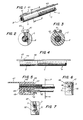
- Figure 1 is a perspective view of the basic embodiment of the present invention, showing the invention attached to an existing articulateable borescope cable.
- Figure 2 is a front end view of the device shown in Figure 1.
- Figure 3 is a rear end view of the device of Figure 1.
- Figure 4 is an elevation view of a modified version of the embodiment shown in Figure 1.
- Figure 5 is a side elevation view of a second embodiment of the apparatus according to the present invention.
- Figure 6 is a front end view of the apparatus of Figure 5.
- Figure 7 is a rear end view of the apparatus of Figure 5.
- Figure 8 is an elevation view of a third embodiment of the apparatus according to the present invention.
- Figure 9 is a front end view of the apparatus of Figure 8.
- Figure 10 is a rear end view of the apparatus of Figure 8.
- Figure 11 is an elevation view of a fourth embodiment of the apparatus according to Figure 1 in which pressurized fluid is provided to the propulsion element of the apparatus by means of an existing spare channel in the borescope cable which the apparatus is attached to.
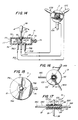
- Figure 12 is a perspective view of a fifth embodiment of the apparatus according to the present invention, attached to the end of an articulateable tube.
- Figure 13 is a perspective view of a sixth embodiment of the invention.
- Figure 14 is a partially sectional view of a differential air flow control valve mechanism for use with the apparatus of Figure 13, shown schematically connected to the apparatus.
- Figure 15 is a upper plan view of the valve mechanism of Figure 14.
- Figure 16 is an upper plan view of an alternate differential air flow control valve mechanism for use with the apparatus of Figure 13.
- Figure 17 is a partially sectional view of the valve mechanism of Figure 16, taken along line 17-17 of Figure 16.
- Figure 18 is an upper, partially sectional view of a modification of the valve mechanism of Figures 16 and 17.
- Figure 19 is a partially sectional view of the mechanism of Figure 18, taken along line 19-19 of Figure 18.
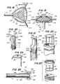
- Figure 20 is a perspective view of a seventh embodiment of the apparatus according to the present invention.
- Figure 21 is a perspective view of a modification of the apparatus of Figure 20.
- Figure 22 is a perspective view of an eighth embodiment of the apparatus according to the present invention.
- Figure 23 is an exploded perspective view of the apparatus of Figure 22 showing how the apparatus is attached to the head of an existing fiberscope.
- Figure 24 is a perspective view of a modification of the apparatus of Figure 22.
- Figure 25 is a sectional elevation view of a ninth embodiment of the apparatus according to the present invention.
- Referring now to Figures 1 through 3, a
device 40 for propelling a flexible borescope is shown attached to the head of a borescope. A typical borescope A which is not part of the present invention, has a central core B comprising a flexible, image conducting bundle of fine, transparent glass or plastic fibers. - Both ends of fiber-optic cable core bundle B are cut perpendicular to the axis of the fibers. The fibers of both transverse end planes of the cable are held in parallel alignment by embedding them in a solid plastic, and both end faces of the bundle are polished. Objects which fall within the conical field of view of the distant end of the fiber-optic bundle are viewable by an observer looking into the rear end of the bundle. Lenses may be provided at either or both ends of the fiber-optic bundle to suit particular viewing requirements.
- The fiber-optic core bundle B of the borescope or fiberscope, as it is sometimes referred to, is usually imbedded within a larger diameter flexible cable assembly C. The cable assembly C provides protection against damage for core bundle B. Also, the cable assembly provides a convenient conduit for transmitting light to illuminate a remote area to be observed. Frequently, the illumination is provided by a bright light source at the observer's end of the cable assembly, the light being conducted to the remote end of the cable assembly by a separate fiber-optic bundle within the cable assembly C.
- The propulsion method and apparatus of the present invention is useable with all types of borescopes. Thus, for example, it may be used with borescopes which use a miniature television camera at the end of an electrical cable rather than a fiber-optic bundle, to receive and transmit images of distant objects.
- A basic embodiment of the present invention is adapted for use with borescopes in which the remote head of the borescope may be bent with respect to the cable connected to the rear of the head in a desired direction by an observer at the opposite end of the fiberscope. Such borescopes are referred to as articulateable, and employ wires leading from the remote head of the borescope to the observer's end of the cable to effect bending of the head end of the borescope in a direction desired by the observer. The capability of being articulated in a single plane is referred to as two-way articulatibility, while the capability of being positioned in all planes is referred to as four-way articulatability. Siegmund, in U.S. Patent No. 4,290,421 discloses an apparatus in which four-way or universal articulation of the end of a borescope is accomplished with a three-wire control system.
- As shown in Figures 1 through 3, the
borescope propulsion device 40 according to the present invention includes a preferably rigid,hollow tube 41 bent into the shape of aU. U-tube 41 may be fabricated from thin gauge plastic or metal tube stock. - As shown in Figure 1,
tube 41 is fastened to the outer end or head portion D of the flexible cable assembly C of articulateable borescope A.U-shaped tube 41 is disposed with both of its legs in parallel alignment with the longitudinal axis of borescope head D. One end ofU-tube 41 is sealed by an air-tight joint to a flexibleair supply tube 42, which extends backward parallel to cable assembly C to an external supply of pressurized air. The other end ofU-tube 41 is open. Thus, when pressurized air is supplied to U-tube 41 viaair supply tube 42, issuance of a backward-flowing jet of air at a relatively high velocity from the open leg of the U-tube produces a forward-directed reaction thrust force on the head D of the borescope cable assembly C. Preferably, the open leg of the U-tube is tapered, forming a convergent nozzle which increases the velocity of expelled fluid, and therefore, increases the thrust force. - Now, since the head D of borescope cable assembly C may be remotely articulated by an operating observer to point in any desired direction, an operator can control the direction of the thrust vector, by using the borescope articulation control system to aim the borescope head in a desired direction. The operator can also control the magnitude of the forward thrust force imparted to the head of the borescope by varying the pressure of air supplied to the inlet of
tube 42. Thus, by applying sufficient air pressure toair supply 42 ofpropulsion device 40, the device and the attached borescope head can literally be flown to any desired location The flying capability permits the borescope head to move in three dimensions, and without requiring contact of the borescope cable with a supporting surface. By pulling the entire cable assembly backwards slightly, it is possible to retract the borescope head from passageways which it has entered, and then to propel the head to different locations. - Since an observer looking into the rear end of the borescope can see what remote location the head of the borescope is pointing to, the observer can effect the propulsion and guidance of the borescope head to an inaccessible inspection area of interest. By using the method and apparatus described, it has been found possible to guide a flying borescope according to the present invention sequentially through all 9 combustors of a JT8 jet turbine engine in approximately 10 minutes. This compares with the four hours that is typically required to thread conventional borescopes through the same engine parts, if it can be done at all. Currently used methods of performing such an inspection require the use of a series of rigid sheathing tubes to guide the borescope cable. These are not required with the method and apparatus of the present invention. Thus, the time, labor, and cost savings effected by the apparatus and method of the present invention are substantial.
- As may be seen best by referring to Figures 2 and 3, the plane of
U-tube 41 is preferably tangent to the outer circumferential surface of flexible cable assembly C. This orientation minimizes the increase in the maximum diameter of the cable assembly and attached U-tube, thereby minimizing the clearance requirements for the combined borescope head and attached propulsion device. - Figure 4 illustrates a modified
version 43 of the device of Figures 1 through 3. In the modified version, ahollow U-tube 44 substantially identical to U-tube 41 of the basic embodiment extends some distance beyond the outer transverse plane of head D fiber-optic cable assembly C. The outward extending portion ofU-tube 44 ensures that the outer transverse plane of the borescope head will not be butted up against an obscuring surface as the cable assembly is propelled forward. This assures the observer of always being able to have an unblocked field of view sufficient to permit him to guide the cable assembly to a desired inspection area. Also, the fixed distance between the entrance aperture of the borescope head and surfaces in contact with the outer end of the U-tube ensures that the surface is at the correct focal length with respect to the optical entrance aperture of the borescope head, and that points within the imaged field of view are a known repeatable distance apart. - Figures 5 through 7 illustrate a second embodiment 45 of the borescope head propulsion device according to the present invention. In side view, the propulsion device 45 has the shape of a generally
rectangular cross-section block 46 with its long axis parallel to the longitudinal axis of head D of a borescope A to which the device is attached. The upper wall ofblock 46 extends forward to form the upper surface of an elongated, thin, flat tab orfinger 47 which extends forward from the block. As shown in the front elevation view (Figure 6)Finger 47 has a generally rectangular transverse cross-sectional shape.Block 46 is also shown to have a generally rectangular cross-sectional shape, although the shape is not essential to the operation of the invention, and could be oval or curved as a matter of design choice. - As shown in Figures 5 through 7, a longitudinally disposed, circular cross-section bore 48 extends through the entire length of
block 46 fromfront face 49 torear face 50 of the block. The axis ofbore 48 is parallel to the upper and lower longitudinal surfaces ofblock 46.Bore 48 is of the proper size to fit over the outer circumferential surface of the head D of borescope A, being secured thereto by an interference fit, adhesive bonding, or any other suitable fastening means. - A smaller diameter,
blind cavity 51 is bored part way forward from therear face 50 ofblock 46, perpendicularly into the block. As may be seen best by referring to rear end view of Figure 7,cavity 51 has a generally oval cross-sectional shape. Anair hose 52 having a substantially smaller cross-sectional area thancavity 51 is inserted part way into the cavity, and secured to a wall of the cavity by an appropriate means, such as adhesive bonding. Clearance between the outer circumferential surface ofair hose 52 and the inner walls ofcavity 51 provide a passageway for air exiting under pressure from the bore ofair hose 52 to escape from the cavity, exiting rearward from the cavity in a direction generally perpendicular to the reartransverse face 50 ofblock 46. - Borescope head propulsion device 45 functions in the same way as has been described above for the basic embodiment of the invention. Air under pressure is supplied to the inlet end of
air hose 52 and controlled by a proportional valve operated by an operator at the viewing end of the cable. Air passing throughair hose 52 enterscavity 51 and escapes rearward through the space between the hose and cavity, provid ing a rearward directed jet stream of air. That air jet produces a forward directed force onblock 46 which tends to pull, in a forward direction, head D and cable assembly C of borescope A, which is attached to the block. By controlling the flow of air intoair hose 52, the operator controls the thrust force applied to the device. By operating the articulation mechanism of the borescope, the operator can also aim the axis of the borescope head, and hence the thrust vector of propulsion device 45, to any desired point in space. Thus, by controlling the pressure of air supplied toair hose 52, and the aiming point of the borescope head, the propulsion device 45 and the attached borescope head can be propelled at a desired rate and guided to a desired location. Moreover, since an operator can view objects within the forward field of view of the borescope at the end of the borescope, he may propel and guide the borescope head to inaccessible areas which he desires to view. Also, since the operator can see inaccessible areas through the borescope, he can propel and guide the borescope head to areas of interest discovered during the course of inspection, such as engine components which show visual evidence of actual or potential defects. -
Finger 47 extends forward from the common plane of the front face of propulsion device 45 and the head D of borescope A. Thus, the front face of the borescope head may not be placed closer to any object than the length offinger 47. This minimum spacing assures that the operator's forward visibility will not be blocked by inadvertent abutment of the front face of the borescope head, containing its optical entrance aperture, against an obscuring surface. The minimum spacing between objects and the entrance aperture in the front face of the borescope head also reduces the possibility of impact or scratch damage to the front face of the fiber optic bundle. - In the embodiments of the borescope head propulsion device described above, the jet thrust vector is parallel to but displaced some distance from the longitudinal axis of the borescope cable assembly to which the device is attached. As a result, a torque is produced about an axis perpendicular to the cable axis and jet tube axis, in addition to the forward thrust force. Therefore, it is necessary to apply a counterbalancing torque if it is required to move the borescope head in a straight line. The borescope articulation mechanism provides a convenient means for applying the required counterbalancing torque when it is desired to propel the borescope head parallel to the axis of the cable.
- In tests using the propulsion device according to the present invention to propel borescopes, it was found that it was easy for an operator to learn to apply the necessary counterbalancing torque. However, a second, counterbalancing jet tube may be provided in a mirror image position on the side of the borescope head opposite the first jet tube, thereby resulting in thrust force without a reaction torque on the borescope head.
- Figures 8 through 10 illustrate a
third embodiment 53 of the borescope head propulsion device according to the present invention. In that embodiment, a generallyrectangular cross-section block 54 has extending through the entire length of the block a longitudinal, circular cross-section bore 55 adapted to receive and retain the outer circumferential surface of the head D of a borescope. The axis ofbore 55 is above the longitudinal center line ofblock 53, and is parallel thereto. - A smaller diameter bore 56 extends through the entire length of
block 54, parallel to and belowbore 55.Bore 56 is adapted to receive and retain flexibleair supply tube 57. Athird bore 58, of smaller diameter than bore 57, extends through the entire length ofblock 54, parallel to and belowbore 57.Bore 58 constitutes a rearward directed jet tube, and is supplied with pressurized air by means ofU-tube 59, which communicates with the front openings of air supply bore 56 and jet tube bore 58. This embodiment of the borescope head propulsion device operates in an exactly analogous manner to that described above for the other embodiments of the invention. - In the embodiments of the invention described above, an external supply tube provides pressurized air to a jet tube which propels the device. If it is desired to provide a larger propulsion force to the fiberscope which the device is attached to, a heavier fluid such as water may be used to pressurize the supply tube, providing a greater mass flow rate and an accompanying increase in thrust.
- As used throughout this disclosure, fluid is understood to include liquids, gases and mixtures of liquids and gases. Thus, for example, a liquid foam containing gas bubbles could be used as a propelling fluid according to the present invention. The expelled fluid could be used to treat or condition parts within an inspected area traversed by the propulsion head. An example of such an application would be the use of a corrosion-inhibiting liquid or liquid foam as a propelling fluid. Use of such a propellant would permit treating otherwise inaccessible metal parts of an apparatus being inspected, such as a turbine engine, with a corrosion inhibiting foam.
- Other multi-phase mixtures in addition to foams may be used as a propelling fluid. A solid-liquid slurry would be an example of another such mixture.
- In sealed or substantially enclosed inspection areas, it may sometimes be necessary or desirable to remove fluid expelled from the reaction jets into the enclosed area. Removal can be accomplished by any convenient means, such as a vacuum tube positioned with its entrance aperture at an efficient collection point for expelled fluid within the space. A vacuum tube could also be fastened to the borescope head, travelling along with the reaction jet.
- Many existing fiberscopes have one or more spare channels into which the user may insert tubes to convey fluids from one end of the fiberscope cable to the other, or wires to convey electrical signals. Such an auxiliary channel may be used advantageously to convey pressurized fluid from the operator's end of the cable to the jet propulsion device of the present invention attached to the remote head of the fiberscope.
- Figure 11 illustrates a fourth embodiment 60 of the borescope propulsion device according to the present invention which utilizes an existing spare channel in a fiberscope cable assembly. In that embodiment, a
hollow U-tube 61, similar to the U-tube 41 used in the basic embodiment of the invention illustrated in Figures 1 and 2, is connected by a fluid-tight joint to the front opening of an unused channel E of a borescope cable assembly C. The rear opening of channel E is connected to a source of pressurized fluid controllable by an operator at the rear end of the cable assembly. Aside from the fact that this embodiment of the invention uses the existing spare channel E of the borescope for conveying pressurized fluid to the jet-thrust producing U-tube 61, the operation of this embodiment is identical to that described above for the basic embodiment of the in vention, which description is therefore not repeated. - Each of the embodiments of the present invention described above comprise accessories for, or modifications of articulateable borescopes. Other embodiments of the invention which provide a propulsion and guidance capability for non-articulateable borescopes will now be described.
- A fifth embodiment of the present invention is shown in Figure 12. The embodiment shown in Figure 12 comprises that basic version of the propulsion and guidance device according to the present invention which is useable with non-articulateable borescopes.
- The
embodiment 62 of the propulsion and guidance device according to the present invention and shown in Figure 12 comprises essentially a U-tube 63 sealingly coupled to an internal channel 64 of anarticulateable cable assembly 65. Any suitable means may be used to provide an articulating capability to the end ofcable assembly 65.Cable assembly 65 is fastened near its front end to the front end of a borescope A in parallel alignment with the borescope head D. Borescope A need not have its own articulation capability. Pressurized fluid is supplied to the rear opening of channel 64. The quantity of the fluid supplied is controlled by an operator, and the aiming point of the flexible end ofarticulateable cable assembly 65, and hence the direction of the reaction thrust vector of the jet stream issuing from the rear orifice of the nozzle end ofU-tube 63, is controlled by an operator exactly as has been described above for the other embodiments of the invention. Since the articulateable cable assembly is fastened to head D of borescope A, the borescope head will be propelled and guided in unison with thearticulateable cable assembly 65. Thus, as shown in the phantom views of Figure 12, the flexible end ofarticulateable cable assembly 65 may be remotely manipulated, placing the ends of the cable assembly and attachedpropulsion device 62 in different orientations with respect to the parallel longitudinal axes ofcable assembly 65 and borescpe head D. - In a modification of the
embodiment 62 of the propulsion device shown in Figure 12,cable assembly 65 need only have articulateability in a single plane. Assuming, for example, that the plane contains the longitudinal center lines ofcable assembly 65 and borescope head D, the thrust vector of the nozzle end oftube 63 may be varied in the plane from its backward pointing position to a forward pointing position, i.e., for a total angular excursion of 180 degrees. Now if borescope head D may be rotated 360 degress, for example, by rotating the operator's end of the cable assembly C to which the borescope head is attached, the thrust vector ofU-tube 63 may be aimed in any arbitrary direction. Thus, articulateability in a single plane ofcable assembly 65 in combination with rotatability of the borescope head D about it own longitudinal axis permits the thrust vector ofpropulsion device 65 to be oriented in any direction in three-dimensional space. - A second modification of
embodiment 62 of the invention propulsion device whown in Figure 12 permits the thrust vector direction of the nozzle end ofU-tube 63 to be varied in a plane containing the U-tube, without requiring any articulateability ofcable assembly 65. In this modification,U-tube 63 is made of a flexible material, and has a restricted diameter nozzle opening. Therefore, when the pressure of fluid conducted intoU-tube 63 bycable assembly 65 becomes sufficiently large, an outward directed, radial force will be exerted differentially on the walls of the curved portion of the tube, tending to straighten it out, i.e., decreasing the bend radius. This bending action is the basis for operation of a sealed tube used in Bourdon-type pressure guages. Such tubes are referred to as Bourdon tubes. - Thus, by varying the pressure of fluid supplied to
U-tube 63, the bend radius and hence the thrust vector direction of the tube can be varied by the Bourdon effect. Combined with the rotatability of the borescope head to which it is attached, the use of a Bourdon-type tube forU-tube 63permits cable assembly 65 to be merely a fluid supply tube, yet permitting the thrust vector of the U-tube to be aimed in any desired direction. - A sixth embodiment of the borescope head propulsion and guidance device according to the present invention is shown in Figure 13. The
embodiment 66 shown in Figure 13 is also useable with fiberscopes not having an independent articulation capability. - As shown in Figure 13, propulsion and
guidance device 66 includes three elongated hollow jet tubes 67 having straight rear sections 68. Rear sections 68 of jet tubes 67 are fastened to the outer cylindrical surface of head D of borescope A, in parallel alignment with the longitudinal axis of the borescope head. Tubes 67 are disposed at 120° increments around the circumference of borescope head D. Other tube arrays are of course possible, such as four tubes at 90° increments. - The forward sections 69 of jet tubes 67 bend outward from the central axis of borescope head D, and backwards at acute angles to the central axis. Thus, the center lines of the rear portions of forward sections 69 of jet tubes 67, which define the direction of jet streams which may issue from the rear orifices of the forward sections, each define an acute angle with the axis of the borescope head, and a 120° degree circumferential angle with respect to each adjacent jet tube.
- The rear opening in the rear section 68 of each jet tube 67 is sealingly joined to a flexible, hollow air supply tube 70 which extends backward along cable assembly C to an external supply of pressurized air. Thus, when pressurized air is supplied to a jet tube 67, issuance of a backward flowing jet of air, at a relatively high velocity, from the rear orifice of forward section 69 of the jet tube produces a reaction thrust force on head D of cable assembly C having a forward directed component. Also, since the axis of forward section 69 of each jet tube 67 is inclined to the longitudinal axis of the head, a bending moment is also applied to the head as a result of the radial component of the thrust produced by the jet.
- If the mass flow rate of fluid expelled from out of the three jet tubes 67 is equal, the three bending moments cancel each other out, resulting in a force vector which lies entirely along the longitudinal axis of head D of fiberscope A. Thus, if the air flow rates in each air supply tube are all the same magnitude, a purely longitudinal, forward directed force will be exerted on fiberscope head D.
- If the air flow rates in each air supply tube 70 for each jet tube 67 are not all equal, a net bending moment will be applied to borescope head D. Thus, by controlling the air flow rates in each supply tube 70 to a specified differential value, the borescope head and flexible cable assembly C attached to the head may bent to a desired aim point, and propelled thereto.
- A differential control valve for providing controllable differential air flow rates to jet tubes 67 of
propulsion device 66 is shown in Figures 14 and 15. As shown in the Figures,control valve 71 has the general shape of a hollow cylindrical box with a disc-shapedcover 72, acylindrical side wall 73, and a disc-shapedbase 74. Ahollow inlet tube 75 projects radially outwards fromcylindrical side wall 73, thebore 76 of the inlet tube communicating with theinterior space 77 of the valve. - The
valve outlet tubes base 74 ofvalve 71. Thebores interior space 77 of the valve, and the upper transverse surfaces of the outlet tubes extend upwards no further than the upper wall surface 80 of disc-shapedbase 74.Valve outlet tubes Outlet tubes air supply tubes jet tubes propulsion device 66. - A generally disc-shaped
slide valve element 81 is slidably positioned above bores 79A, 79B and 79C ofoutlet tubes interior space 77 ofvalve 71, as will now be described. - As may be seen best by referring to Figure 14, a
pivot ball 82 is fastened to the upper surface ofslide valve element 81, centered on the longitudinal center line of the valve element. An elongated cylindricalvalve operating rod 83 has a concave, disc-shaped cavity 84 at its lower end which fits conformally overpivot ball 82. Operatingrod 83 extends upward through acentral hole 85 in disc-shapedcover 72 ofcontrol valve 71. The upper end of operatingrod 83 is covered with acylindrical boot 86 to provide a convenient grasping surface for the thumb and forefinger of an operator. - As shown in Figure 14, a flexible, annular-shaped rubber diaphragm 87 fits coaxially over operating
rod 83, forming an airtight seal. Also, the outer annular surface of the diaphragm is joined in an airtight seal tolower surface 88 of disc-shapedcover 72. Whenvalve 71 is pressurized, the pressure withininterior space 77 of the valve produces a downward force onslide valve element 81, tending to keep it in flat contact with upper wall surface 80 of disc-shapedbase 74. However, a downward force may be applied in the absence of pressurization by ahelical compression spring 89 positioned coaxially around that portion of operatingrod 83 withininterior space 77 ofvalve 71. The upper coil ofcompression spring 89 abutslower surface 88 of disc-shapedcover 72, while the lower coil of the spring passes through a transverse hole 90 in the lower end of operatingrod 83, just above concave cavity 84. Thus positioned,compression spring 89 applies a downward bias force on operatingrod 83, and therefore, on disc-shapedvalve element 81, keeping the lower surface ofvalve element 81 in intimate contact with the upper wall surface 80 of disc-shapedbase 74. - As may be seen best by referring to Figure 15, with operating
rod 83 in a vertical or neutral position, disc-shapedvalve element 81 obstructs equal cross-sectional areas ofbores valve outlet tubes jet tube propulsion device 66 will be equal, producing a forward reaction thrust vector colinear with the longitudinal axis of borescope head D to whichjet tubes inlet tube 75 ofcontrol valve 71. - If the upper end of operating
rod 83 is pivoted in a vertical plane towardsvalve outlet tube 78C sufficiently far, disc-shapedvalve element 81 will completely coverbores outlet tubes 78A and 78B, and completely uncoverbore 79C ofoutlet tube 78C. Thus, with operatingrod 83 pivoted to the described position, maximum air flow will be provided tojet tube 67C supplied byvalve outlet tube 78C, while no pressurized air will be provided tojet tubes jet tube 67C will produce thrust, resulting in a forward thrust component and a moment tending to bend borescope head D in a plane containing the longitudinal axis of head D andjet tube 67C, in a direction away fromjet tube 67C. The magnitude of this force can be increased or decreased by increasing or decreasing the pressure of air supplied toinlet tube 75 ofvalve 71. - In an exactly analogous fashion to that described above, operating
rod 83 may be swivelled by an operator to any position within a cone defining the maximum deviation of the center line of the operating rod from the center line ofvalve 71. In that way, an operator can aim the resultant thrust vector ofjet tubes rod 83 thus functions as a joy stick, similar in function to the joy stick used to control the flight direction of an airplane. - A second embodiment of a differential control valve assembly useable with
propulsion device 66 is shown in Figures 16 and 17. As shown in the Figures,differential control valve 91 includes a hollow generally cylindrical box having a disc-shapedcover 92,cylindrical side wall 93, and a disc-shapedbase 94. Ahollow inlet tube 95 projects perpendicularly downward from disc-shapedbase 74, coaxial with the cylindrical axis ofvalve 91. Thebore 96 ofinlet tube 95 communicates with theinterior space 97 of the valve. - Three
valve outlet tubes cylindrical side wall 93 ofvalve 91.Valve outlet tubes cylindrical side wall 93. Thebores 99A, 99B and 99C of the valve outlet tubes communicate with theinterior space 97 of the valve. The inner transverse surface planes of the outlet tubes extend radially inward no further than the inner circumferential wall surface 100 ofcylindrical side wall 93 of the valve.Outlet tubes air supply tubes jet tubes propulsion device 66. - A generally disc-shaped slide valve element 101 is positioned in a generally coaxial position within the cylindrical
interior space 97 ofvalve 91. Slide valve element 101 includes an elongated, coaxial,cylindrical operating rod 102 which extends perpendicularly upwards from the flat upper surface 103 of the valve element.Operating rod 102 extends upward through acentral hole 104 in disc-shapedcover 92 ofcontrol valve 91. - As shown in Figure 17, a flexible annular-shaped
rubber diaphragm 105 fits coaxially over the outer circumferential surface of operatingrod 102, and makes an airtight seal with that surface.Diaphragm 105 has a series of radially disposed convolutions 106 which gives the transverse cross-sectional view of the diaphragm an undulating, wave-like appearance. The outer annular surface ofdiaphragm 105 is joined in an airtight seal to thelower surface 107 of disc-shapedcover 92. - The convolutions 106 in
diaphragm 105 permit an operator to moveoperating rod 102 and integral disc-shaped slide valve element 101 in a desired radial direction away from the cylindrical axis ofvalve control mechanism 91. The flexibility ofdiaphragm 105 also permits operatingrod 102 and slide valve element 101 to be moved up and down with respect to disc-shapedbase 94 of the inlet tube. By moving slide valve element 101 downwards towards the entrance to bore 96 ofair inlet tube 95, air flow intointerior space 97 ofvalve 91 is reduced. This reduces the rates of air flow out throughvalve outlet tubes jet tubes rod 102, an operator can diminish or increase the magnitude of thrust applied topropulsion device 66. - By moving
operating rod 102 and slide valve element 101 from a central, neutral position radially outwards towards avalve outlet tube jet tubes - A modified version of
valve control mechanism 91 is shown in Figure 18 and 19. As may be seen best by referring to Figure 18, modifiedcontrol valve 108 has a workingspace 109 having in a transverse cross-sectional view the general shape of an equilateral triangle, as compared with the circular- shaped working space ofvalve 91. The transverse outline of workingspace 109 deviates from that of a triangle in that the sides of the outline are convex rather than straight, and join each other in arcuate, as opposed to angular vertices. - Three
valve outlet tubes valve 108, the center lines of each tube bisecting a separate one of each of the three interior angles of the workingspace 109. Thus,valve outlet tubes side wall 112 ofvalve 108. The bores 111A, 111B and 111C of the valve outlet tubes communicate with theinterior space 109 of the valve, and the inner transverse planes of the outlet tubes extend radially inward no further than theinner wall surface 113 ofside wall 112. - As shown in Figure 18,
valve 108 includes aslide valve element 114 having in a transverse cross-sectional view the general outline of a trefoil. The distance below the center of the trefoil shape and the outer surface of each convex trefoil lobe 115 ofvalve element 114 is slightly less than the distance between the center of triangular workingspace 109 and each of its vertices, thus permitting movement of the valve element lobes away from or towards a selected valve outlet tube. However, the minimum transverse dimension ofvalve element 114 is sufficiently large to prevent substantial rotation of the element, thereby confining each lobe 115 to the vicinity of a particular vertice and associated valve outlet tube of triangular workingspace 109. - As may be seen best by referring to Figure 19, working
space 109 ofvalve 91 has, in a central longitudinal cross-sectional view, generally flat parallel upper and lower surfaces, and convex, arcuate sides disposed symmetrically about the axis of each valve outlet tube. Ahollow inlet tube 116 projects perpendicularly downwards from thebase 117 ofvalve 108. Thebore 118 of theinlet tube 116 communicates with the workingspace 109 of the valve. -
Slide valve element 114 includes an elongated, coaxialcylindrical operating rod 123 which extends perpendicularly upwards from the flatupper surface 124 of the valve element.Operating rod 123 extends upward through ahole 125 in the transverse upper wall 126 ofvalve 108. A flexible, annular-shaped,convoluted diaphragm 127 forms an airtight seal betweenoperating rod 123 and upper wall 126 ofvalve 108. -
Modified valve 108 is used to control the magnitude and direction of thrust provided byjet tubes basic embodiment 91 of the valve shown in Figures 16 and 17. In modifiedversion 108, more positive control of the difference between flow rates of air issuing from each valve outlet tube is made possible by the cooperative interelationship between the convex arcuate shapes of the lobes 115 of theslide valve element 104 and the complementarily shaped concave regions of the valve housing centered around each valve outlet tube. - Figure 20 illustrates a seventh embodiment of the propulsion and guidance device according to the present invention.
- As shown in Figure 20, the seventh embodiment 131 of the propulsion and guidance device according to the present invention includes three hollow,
elongated jet tubes 132. Eachjet tube 132 is preferably formed from a single cylindrical tube which has had a right angle bend imparted to it, forming a straight rear section 133 and a shorter front sec tion 134 extending outwards at ninety degrees with respect to the rear section. Rear sections 133 ofjet tubes 132 are fastened to the outer cylindrical surface of head D of borescope A, in parallel alignment with the longitudinal axis of the borescope head.Jet tubes 132 are disposed at 120° increments around the circumference of borescope head D. The axis of each front section 134 of eachjet tube 132 is radially disposed with respect to the longitudinal axis of borescope head D. Thus, when pressurized air is differentially supplied tojet tubes 132, as for example by one of the three valves described above, a bending moment of controlled magnitude and direction will be applied to borescope head D, permitting the head to be aimed in a desired direction. - Propulsion of guidance and propulsion device 131 is provided by supplying air under pressure to
U-shaped propulsion tube 135.Propulsion tube 135 is fastened to the outer cylindrical surface of head D of borescope A, in parallel alignment with the longitudinal axis of the borescope head. Preferably,propulsion tube 135 is spaced midway between pairs ofadjacent jet tubes 132. - In some applications for the borescope propulsion and guidance device according to the present invention, it would be desirable to have the capability of translating the head of a borescope without tilting it and without moving it forward or backward, in the manner of a cobra raising its head while maintaining the axis of its skull, and hence its line of sight, fixed in a horizontal direction. A modified version of the invention, shown in Figure 21 provides that capability.
- As shown in Figure 21, a propulsion and
guidance device 140 which is a modification of the embodiment 131 shown in Figure 19 includes, in addition to the element of the basic embodiment additional thruster tubes 141. Thruster tubes 141 are hollow cylindrical tubes sealed at one end and having an opening at the other end for the admission of pressurized air. Thruster tubes 141 are fastened to the outer cylindrical surface of head D of borescope A, in parallel alignment with the longitudinal axis of the borescope. The thruster tubes are disposed at 120° increments around the circumference of borescope head D. - Each thruster tube 141 contains in the outer portion of its cylindrical wall a radially disposed, tapered nozzle perforation 142. The axis of each perforation is radially directed with respect to the longitudinal axis of the borescope head. Thus, when air under pressure issues from a perforation 142, a radially inwardly directed reaction force is exerted on the longitudinal center line of borescope head D. A single such reaction force would produce a bending moment on the borescope head. However, a reaction force resulting from air under pressure issuing from
jet tube 132 longitudinally spaced from perforation 142 results in a counterbalancing moment. Therefore, by providing pairs of radial thrust forces by means of perforation 142 in thrust tube 141, counter-balancing the moment produced byjet tube 132, borescope head may be translated in any desired direction while maintaining its longitudinal axis in any desired orientation, as for example, horizontal. - The addition of thrusters 141 displaced rearward from
jet tubes 132 permits the application of radial force moments rearward of those produced by the front jet tubes. By separately controlling the thrust produced by the front jet tubes and rear thrusters, the borescope head can be tilted as desired. In those cases where it is desired to be able to levitate or tilt a portion of the cable attached to the rear of the borescope head along with the head, additional radially directed thrusters may be installed along the length of the cable as required. - An eighth embodiment of the borescope propulsion and guidance device according to the present invention is shown in Figure 22. The
embodiment 150 shown in Figure 22 is for use with articulateable borescopes. It may be attached as an accessory to such borescopes without increasing the diameter of the combination. Thus, the minimum size of passageways through which the borescope may travel is not increased. As shown in the Figure,propulsion device 150 includes ahollow ring 151 supported parallel to the front, transverse face of borescope head D by means of thin, elongated, longitudinally disposedsupport rods 152 joining the facing transverse surfaces of the ring and borescope head.Ring 151 contains a plurality of generally rearwardly directedjet holes 153, anair supply tube 154 provides pressurized air to ring 151. Air escaping fromjet holes 153 imparts a forward thrust to ring 151,support rods 152 and borescope head D. As shown in the Figure, a spare channel with the borescope cable assembly C may be used to containair supply tube 154. - Figure 23 is an exploded perspective view of one form of the apparatus of Figure 21 which is especially well adapted to easy attachment to an existing borescope head. In the embodiment 155 shown in Figure 23,
support rods 152 are attached at their lower ends to asolid ring 156.Ring 156 is attached to borescope head D by removing ferrule F from the borescope head, placingring 156 flat down on the outer transverse face of the borescope head, sliding the ferrule down overhollow ring 151,support rods 152 andsolid support ring 156, and threading the ferrule tightly down on the external threads of the borescope head, thereby securing the support ring to the borescope head. - Figure 24 illustrates another modification of the ring propulsion device of Figures 22 and 23. In the
embodiment 157, an air supply andsupport tube 158 is formed with anintegral propulsion ring 159 having a plurality of rearwardly directed jet holes 160. - A ninth embodiment of the propulsion and control device according to the present invention is shown in Figure 25. That embodiment is intended for use with articulateable borescopes.
- The
embodiment 161 shown in Figure 25 uses an air supply tube mounted coaxially over cable assembly C of borescope A to supply pressurized air topropulsion head 162 of the device. -
Propulsion head 162 includes a generallycylindrical cap 163 having acentral hole 164 adapted to fit over borescope head D, and a rearward extending, coaxial,cylindrical flange 165 adapted to insertibly receive air supply tube 166. Anannular space 167 is formed between the inner circumferential wall ofcap 163 and the outer circumferential wall ofcylindrical flange 165.Perforations 168 are provided in the cylindrical wall offlange 165, allowing pressurized air to enterannular space 167 from air supply tube 166. A flat, annular-shapedring 169 fastened coaxially around the outer circumferential wall ofcoaxial flange 165 is positioned in longitudinal alignment with the rear transverse surface ofcylindrical cap 163, and is sealingly joined to the inner circumferential wall of the cap.Annular ring 169 contains a plurality ofjet holes 170 spaced at regular circumferential angles. Thus, pressurized air inannular space 167 may escape rearward throughjet holes 170, providing forward thrust topropulsion head 162. - In a variation of the embodiment of the propulsion and guidance device shown in Figure 13, means are provided to vary the ratio between radial and longitudinal thrust vectors for a given jet tube as a function of air pressure. Thus, if jet tube 67 is made somewhat flexible, sufficiently high air pressure within the tube will cause the tube to bend in a direction which decreases its original bend radius, i.e., in a direction which increases the intersection angle between the longitudinally disposed rear portion and angled side portion of the jet tube. Thus, higher air pressure supplied to a flexible jet tube will increase the radial component of thrust relative to the longitudinal component.
- In those embodiments of the propulsion and control device according to the present invention which use multiple jet tubes to effect steering, such as those shown in Figures 13 and 19, reduction of the number of air supply tubes required is possible. By providing a selector valve in the borescope head which is remotely controllable by means of electrical control wires or the like, only a single supply tube for pressurized air need be connected to the head.
- In another variation of the present invention, a gas generator located within the borescope head would be remotely controlled to provide pressurized gas to selected propulsion jets.
- In the novel methods and devices for propelling and guiding a borescope by fluid driven reaction jets described above, it has been assumed that guidance commands were generated by a human operator who used the image transmitting capabilities of the borescope to visually guide the borescope head to a desired location. It would be within the spirit of the present invention to use means other than a human operator to generate guidance signals for use by the invention. Moreover, the propulsion and guidance method and apparatus according to the present invention could be used to propel and guide sensors different than imaging borescopes.
- For example, if the propulsion and guidance device according to the present invention were attached to a magnetometer head at the remote end of a flexible cable, a conventional serve control module at the proximal end of the cable could generate command signals for the device which would propel the magnetometer head to regions experiencing anomalous magnetic fields. In an exactly analgous fashion, sensors responsive to other influences, such as ionizing radiation from radioactive materials, could be used to generate command signals for the propulsion and guidance devices according to the present invention, propelling and guiding the sensor to regions of high or low magnitudes of such influences, as desired.
Claims (57)
Applications Claiming Priority (2)
| Application Number | Priority Date | Filing Date | Title |
|---|---|---|---|
| US06/854,295 US4735501A (en) | 1986-04-21 | 1986-04-21 | Method and apparatus for fluid propelled borescopes |
| US854295 | 1986-04-21 |
Publications (3)
| Publication Number | Publication Date |
|---|---|
| EP0242428A2 true EP0242428A2 (en) | 1987-10-28 |
| EP0242428A3 EP0242428A3 (en) | 1989-09-27 |
| EP0242428B1 EP0242428B1 (en) | 1994-10-19 |
Family
ID=25318286
Family Applications (1)
| Application Number | Title | Priority Date | Filing Date |
|---|---|---|---|
| EP86110802A Expired - Lifetime EP0242428B1 (en) | 1986-04-21 | 1986-08-05 | Apparatus for fluid propelled borescopes |
Country Status (5)
| Country | Link |
|---|---|
| US (1) | US4735501A (en) |
| EP (1) | EP0242428B1 (en) |
| JP (1) | JPH0656364B2 (en) |
| CA (1) | CA1297361C (en) |
| DE (1) | DE3650105T2 (en) |
Cited By (8)
| Publication number | Priority date | Publication date | Assignee | Title |
|---|---|---|---|---|
| US4991957A (en) * | 1987-09-08 | 1991-02-12 | Olympus Optical Co., Ltd. | Borescope apparatus |
| EP0433181A1 (en) * | 1989-12-15 | 1991-06-19 | Welch Allyn, Inc. | Mushroom hook cap for borescope |
| US5096292A (en) * | 1987-09-08 | 1992-03-17 | Olympus Optical Co., Ltd. | Borescope apparatus |
| WO1994019048A1 (en) * | 1993-02-27 | 1994-09-01 | KLINIKUM DER ALBERT-LUDWIGS-UNIVERSITäT FREIBURG | Catheter |
| GB2495636A (en) * | 2011-10-13 | 2013-04-17 | Honda Motor Co Ltd | Hole inspection method and hole inspection device |
| DE102007017517B4 (en) * | 2007-04-13 | 2016-03-10 | Siemens Aktiengesellschaft | Navigable endoscopy capsule |
| US10080481B2 (en) | 2005-02-10 | 2018-09-25 | G.I. View Ltd. | Advancement techniques for gastrointestinal tool with guiding element |
| US10226600B2 (en) | 2008-07-30 | 2019-03-12 | G.I. View Ltd. | System and method for enhanced maneuverability |
Families Citing this family (70)
| Publication number | Priority date | Publication date | Assignee | Title |
|---|---|---|---|---|
| JPS6365413A (en) * | 1986-09-08 | 1988-03-24 | Sumitomo Electric Ind Ltd | Optical cable provided with bending mechanism |
| US4883355A (en) * | 1987-09-03 | 1989-11-28 | Welch Allyn, Inc. | Slotted thrusters for fluid propelled borescopes |
| JPH02287508A (en) * | 1989-04-28 | 1990-11-27 | Olympus Optical Co Ltd | Observing method by endoscope device and endoscope |
| JP2923301B2 (en) * | 1989-04-28 | 1999-07-26 | オリンパス光学工業株式会社 | Endoscope apparatus and observation method using endoscope |
| JP2892659B2 (en) * | 1988-11-24 | 1999-05-17 | オリンパス光学工業株式会社 | Endoscope device |
| JPH02250018A (en) * | 1988-12-16 | 1990-10-05 | Olympus Optical Co Ltd | Endoscope device |
| US5505687A (en) * | 1992-05-14 | 1996-04-09 | The United States Of America As Represented By The Department Of Health And Human Services | Device for measuring incident light in a body cavity |
| US5575751A (en) * | 1992-05-14 | 1996-11-19 | The United States Of America As Represented By The Department Of Health And Human Services | Device for measuring incident light in a body cavity |
| WO1994005989A1 (en) * | 1992-09-08 | 1994-03-17 | Kipp Jens Werner | Process and device for inspecting and/or servicing and repairing subsidiary canals branching off from a main drain |
| DE4313929C2 (en) * | 1993-04-28 | 1996-06-20 | Jt Elektronik Gmbh | Device for inspecting house connections with a cleaning option |
| US5311639A (en) * | 1993-05-26 | 1994-05-17 | Avco Corporation | System for detecting and removing foreign object debris |
| US5487661A (en) * | 1993-10-08 | 1996-01-30 | Dentsply International, Inc. | Portable dental camera and system |
| GB9324334D0 (en) * | 1993-11-26 | 1994-01-12 | Sensor Dynamics Ltd | Apparatus for the remote measurement of physical parameters |
| US6532839B1 (en) * | 1996-03-29 | 2003-03-18 | Sensor Dynamics Ltd. | Apparatus for the remote measurement of physical parameters |
| GB9619470D0 (en) | 1996-09-18 | 1996-10-30 | Univ London | Imaging apparatus |
| US20020137890A1 (en) * | 1997-03-31 | 2002-09-26 | Genentech, Inc. | Secreted and transmembrane polypeptides and nucleic acids encoding the same |
| IL128286A (en) * | 1999-01-29 | 2004-01-04 | Sightline Techn Ltd | Propulsion of a probe in the colon using a flexible sleeve |
| US6699179B2 (en) | 2000-01-27 | 2004-03-02 | Scimed Life Systems, Inc. | Catheter introducer system for exploration of body cavities |
| US6517477B1 (en) * | 2000-01-27 | 2003-02-11 | Scimed Life Systems, Inc. | Catheter introducer system for exploration of body cavities |
| US6530439B2 (en) * | 2000-04-06 | 2003-03-11 | Henry B. Mazorow | Flexible hose with thrusters for horizontal well drilling |
| US6599033B1 (en) * | 2000-10-30 | 2003-07-29 | Infineon Technologies Ag | Device for sealing a coupling unit for an optoelectronic component against contaminants |
| US7262797B2 (en) * | 2001-02-22 | 2007-08-28 | Ge Inspection Technologies Lp | Method and system for storing calibration data within image files |
| US7170677B1 (en) * | 2002-01-25 | 2007-01-30 | Everest Vit | Stereo-measurement borescope with 3-D viewing |
| US20030182754A1 (en) * | 2002-03-27 | 2003-10-02 | O'brien Daniel J. | Sheath for integrating sewer hose and TV cable |
| EP1618736A2 (en) * | 2003-01-29 | 2006-01-25 | Everest-VIT, Inc. | Remote video inspection system |
| US20040183900A1 (en) * | 2003-03-20 | 2004-09-23 | Everest Vit | Method and system for automatically detecting defects in remote video inspection applications |
| US7833176B2 (en) | 2003-08-13 | 2010-11-16 | G. I. View Ltd. | Pressure-propelled system for body lumen |
| US8419678B2 (en) | 2004-01-09 | 2013-04-16 | G.I. View Ltd. | Pressure-propelled system for body lumen |
| ES2546355T3 (en) | 2004-01-09 | 2015-09-22 | G.I. View Ltd. | Pressure propelled system for body light |
| GB0409485D0 (en) | 2004-04-28 | 2004-06-02 | Ucl Biomedica Plc | Fluid propelled endoscope |
| GB0409474D0 (en) | 2004-04-28 | 2004-06-02 | Ucl Biomedica Plc | Colonoscope and a colon cleaning method for use therewith |
| US7357182B2 (en) * | 2004-05-06 | 2008-04-15 | Horizontal Expansion Tech, Llc | Method and apparatus for completing lateral channels from an existing oil or gas well |
| US20060278393A1 (en) * | 2004-05-06 | 2006-12-14 | Horizontal Expansion Tech, Llc | Method and apparatus for completing lateral channels from an existing oil or gas well |
| WO2005110186A2 (en) | 2004-05-14 | 2005-11-24 | G.I. View Ltd. | Omnidirectional and forward-looking imaging device |
| US7422559B2 (en) | 2004-06-16 | 2008-09-09 | Ge Inspection Technologies, Lp | Borescope comprising fluid supply system |
| CN101703387B (en) | 2005-01-06 | 2013-10-23 | G.I.视频有限公司 | Gastrointestinal tool over guiding element |
| US7956888B2 (en) * | 2005-06-22 | 2011-06-07 | Ge Inspection Technologies, Lp | Remote video inspection system integrating audio communication functionality |
| EP1909633B1 (en) * | 2005-06-24 | 2011-11-23 | GE Inspection Technologies, LP | Insertion tube storage carousel |
| US9241614B2 (en) | 2005-08-01 | 2016-01-26 | G.I. View Ltd. | Tools for use in esophagus |
| US8430809B2 (en) | 2005-08-01 | 2013-04-30 | G. I View Ltd. | Capsule for use in small intestine |
| US20070156021A1 (en) * | 2005-09-14 | 2007-07-05 | Bradford Morse | Remote imaging apparatus having an adaptive lens |
| US20070091183A1 (en) * | 2005-10-21 | 2007-04-26 | Ge Inspection Technologies, Lp | Method and apparatus for adapting the operation of a remote viewing device to correct optical misalignment |
| GB0601327D0 (en) * | 2006-01-24 | 2006-03-01 | Rolls Royce Plc | Maintenance method |
| US7679041B2 (en) * | 2006-02-13 | 2010-03-16 | Ge Inspection Technologies, Lp | Electronic imaging device with photosensor arrays |
| US8368749B2 (en) * | 2006-03-27 | 2013-02-05 | Ge Inspection Technologies Lp | Article inspection apparatus |
| US8213676B2 (en) | 2006-12-20 | 2012-07-03 | Ge Inspection Technologies Lp | Inspection apparatus method and apparatus comprising motion responsive control |
| US9633426B2 (en) | 2014-05-30 | 2017-04-25 | General Electric Company | Remote visual inspection image capture system and method |
| US8810636B2 (en) | 2006-12-20 | 2014-08-19 | Ge Inspection Technologies, Lp | Inspection apparatus method and apparatus comprising selective frame output |
| US8118733B2 (en) * | 2006-12-22 | 2012-02-21 | Ge Inspection Technologies, Lp | Heat protection systems and methods for remote viewing devices |
| US8625434B2 (en) * | 2006-12-29 | 2014-01-07 | Ge Inspection Technologies Lp | IP based voice communication enabled inspection system |
| US8514278B2 (en) * | 2006-12-29 | 2013-08-20 | Ge Inspection Technologies Lp | Inspection apparatus having illumination assembly |
| US7902990B2 (en) * | 2007-10-26 | 2011-03-08 | Ge Inspection Technologies, Lp | Battery and power management for industrial inspection handset |
| US8767060B2 (en) * | 2007-10-26 | 2014-07-01 | Ge Inspection Technologies, Lp | Inspection apparatus having heat sink assembly |
| US8253782B2 (en) * | 2007-10-26 | 2012-08-28 | Ge Inspection Technologies, Lp | Integrated storage for industrial inspection handset |
| US20090106948A1 (en) * | 2007-10-26 | 2009-04-30 | Lopez Joseph V | Method and apparatus for retaining elongated flexible articles including visual inspection apparatus inspection probes |
| US8310604B2 (en) * | 2007-10-26 | 2012-11-13 | GE Sensing & Inspection Technologies, LP | Visual inspection apparatus having light source bank |
| US9566415B2 (en) | 2008-05-05 | 2017-02-14 | Endogene Limited | Method and apparatus for advancing a probe |
| US8186459B1 (en) | 2008-06-23 | 2012-05-29 | Horizontal Expansion Tech, Llc | Flexible hose with thrusters and shut-off valve for horizontal well drilling |
| CA2741206C (en) | 2008-11-03 | 2016-01-12 | G.I. View Ltd | Remote pressure sensing system and method thereof |
| US20100198876A1 (en) * | 2009-02-02 | 2010-08-05 | Honeywell International, Inc. | Apparatus and method of embedding meta-data in a captured image |
| US9519814B2 (en) | 2009-06-12 | 2016-12-13 | Hand Held Products, Inc. | Portable data terminal |
| DE102009057284B4 (en) * | 2009-12-07 | 2020-07-30 | Ritec Rohrinspektionstechnik Gmbh | Device for the inspection and / or cleaning of pipes for industrial, domestic and commercial waste water, in particular sewer pipes for waste water |
| JP5514077B2 (en) * | 2010-11-05 | 2014-06-04 | 富士フイルム株式会社 | Endoscope hood and endoscope system |
| JP5675334B2 (en) * | 2010-12-28 | 2015-02-25 | オリンパス株式会社 | Endoscope |
| US8836937B2 (en) | 2012-11-19 | 2014-09-16 | General Electric Company | Actuatable visual inspection device |
| JP6223049B2 (en) * | 2013-08-01 | 2017-11-01 | オリンパス株式会社 | Blade inspection system |
| CN108159551A (en) * | 2018-01-02 | 2018-06-15 | 庞兴学 | Regulate and control head end active travelling conduit and its method |
| US11103964B2 (en) * | 2018-12-06 | 2021-08-31 | General Electric Company | Service apparatus for use with rotary machines |
| US20210102870A1 (en) * | 2019-10-04 | 2021-04-08 | General Electric Company | Insertion apparatus for use with rotary machines |
| US11781698B2 (en) | 2019-11-19 | 2023-10-10 | South Dakota Board Of Regents | Modular robotic crawler with hybrid locomotion for inspection of small diameter pipe |
Citations (4)
| Publication number | Priority date | Publication date | Assignee | Title |
|---|---|---|---|---|
| GB650053A (en) * | 1941-11-24 | 1951-02-14 | Clovis De Paiva Aguiar | Nozzles for flexible tubes for insertion in body cavities |
| FR2267800A1 (en) * | 1974-04-17 | 1975-11-14 | Anvar | Catheter insertion system - uses auxiliary fluid injected in catheter and forming propulsion jets |
| US4290421A (en) * | 1979-01-08 | 1981-09-22 | American Optical Corporation | Fiberscope |
| US4403985A (en) * | 1981-05-12 | 1983-09-13 | The United States Of America As Represented By The Department Of Health And Human Services | Jet controlled catheter |
Family Cites Families (9)
| Publication number | Priority date | Publication date | Assignee | Title |
|---|---|---|---|---|
| US2461797A (en) * | 1944-10-23 | 1949-02-15 | Aerojet Engineering Corp | Reaction propelled device for operation through water |
| US2963543A (en) * | 1956-12-10 | 1960-12-06 | Gen Precision Inc | Underwater television propulsion apparatus |
| US3354658A (en) * | 1965-08-12 | 1967-11-28 | Leonardi Sam | Apparatus for performing underwater operations |
| GB1227342A (en) * | 1967-03-31 | 1971-04-07 | ||
| GB1296534A (en) * | 1969-12-09 | 1972-11-15 | ||
| US3694094A (en) * | 1970-12-22 | 1972-09-26 | Nasa | Borescope with variable angle scope |
| US4042823A (en) * | 1976-03-17 | 1977-08-16 | The United States Of America As Represented By The Secretary Of The Navy | Optical scanner |
| JPS5784030A (en) * | 1980-11-12 | 1982-05-26 | Olympus Optical Co | Endoscope apparatus |
| JPS58189604A (en) * | 1982-04-30 | 1983-11-05 | Sumitomo Electric Ind Ltd | Underwater fiber scope |
-
1986
- 1986-04-21 US US06/854,295 patent/US4735501A/en not_active Expired - Lifetime
- 1986-08-05 EP EP86110802A patent/EP0242428B1/en not_active Expired - Lifetime
- 1986-08-05 DE DE3650105T patent/DE3650105T2/en not_active Expired - Fee Related
- 1986-08-18 CA CA000516152A patent/CA1297361C/en not_active Expired - Lifetime
- 1986-12-09 JP JP61293317A patent/JPH0656364B2/en not_active Expired - Lifetime
Patent Citations (4)
| Publication number | Priority date | Publication date | Assignee | Title |
|---|---|---|---|---|
| GB650053A (en) * | 1941-11-24 | 1951-02-14 | Clovis De Paiva Aguiar | Nozzles for flexible tubes for insertion in body cavities |
| FR2267800A1 (en) * | 1974-04-17 | 1975-11-14 | Anvar | Catheter insertion system - uses auxiliary fluid injected in catheter and forming propulsion jets |
| US4290421A (en) * | 1979-01-08 | 1981-09-22 | American Optical Corporation | Fiberscope |
| US4403985A (en) * | 1981-05-12 | 1983-09-13 | The United States Of America As Represented By The Department Of Health And Human Services | Jet controlled catheter |
Cited By (12)
| Publication number | Priority date | Publication date | Assignee | Title |
|---|---|---|---|---|
| US4991957A (en) * | 1987-09-08 | 1991-02-12 | Olympus Optical Co., Ltd. | Borescope apparatus |
| US5096292A (en) * | 1987-09-08 | 1992-03-17 | Olympus Optical Co., Ltd. | Borescope apparatus |
| EP0433181A1 (en) * | 1989-12-15 | 1991-06-19 | Welch Allyn, Inc. | Mushroom hook cap for borescope |
| WO1994019048A1 (en) * | 1993-02-27 | 1994-09-01 | KLINIKUM DER ALBERT-LUDWIGS-UNIVERSITäT FREIBURG | Catheter |
| US10080481B2 (en) | 2005-02-10 | 2018-09-25 | G.I. View Ltd. | Advancement techniques for gastrointestinal tool with guiding element |
| DE102007017517B4 (en) * | 2007-04-13 | 2016-03-10 | Siemens Aktiengesellschaft | Navigable endoscopy capsule |
| US10226600B2 (en) | 2008-07-30 | 2019-03-12 | G.I. View Ltd. | System and method for enhanced maneuverability |
| GB2495636A (en) * | 2011-10-13 | 2013-04-17 | Honda Motor Co Ltd | Hole inspection method and hole inspection device |
| CN103048328A (en) * | 2011-10-13 | 2013-04-17 | 本田技研工业株式会社 | Hole inspection method and hole inspection device |
| CN103048328B (en) * | 2011-10-13 | 2015-04-29 | 本田技研工业株式会社 | Hole inspection method and hole inspection device |
| US9078558B2 (en) | 2011-10-13 | 2015-07-14 | Honda Motor Co., Ltd. | Hole inspection method and hole inspection device |
| GB2495636B (en) * | 2011-10-13 | 2016-08-31 | Honda Motor Co Ltd | Hole inspection method and hole inspection device |
Also Published As
| Publication number | Publication date |
|---|---|
| DE3650105T2 (en) | 1995-05-11 |
| JPH0656364B2 (en) | 1994-07-27 |
| EP0242428B1 (en) | 1994-10-19 |
| DE3650105D1 (en) | 1994-11-24 |
| US4735501B1 (en) | 1990-11-06 |
| EP0242428A3 (en) | 1989-09-27 |
| JPS62251639A (en) | 1987-11-02 |
| CA1297361C (en) | 1992-03-17 |
| US4735501A (en) | 1988-04-05 |
Similar Documents
| Publication | Publication Date | Title |
|---|---|---|
| US4735501A (en) | Method and apparatus for fluid propelled borescopes | |
| US4290421A (en) | Fiberscope | |
| US4893613A (en) | Endoscope construction with means for controlling rigidity and curvature of flexible endoscope tube | |
| US8337455B2 (en) | Steerable device and system | |
| US11950763B2 (en) | Self-propelled soft robot body | |
| US5960145A (en) | Optical fiber image conduit and method using same | |
| CA2898586C (en) | Integrated steering device | |
| US5140975A (en) | Insertion tube assembly for probe with biased bending neck | |
| US4403985A (en) | Jet controlled catheter | |
| US5050585A (en) | Sheathed endoscope | |
| US4846573A (en) | Shape memory effect alloy pull wire articulator for borescopes | |
| US5275608A (en) | Generic endoscopic instrument | |
| WO1984002196A1 (en) | Flexible inspection system | |
| EP0587506A1 (en) | Control mechanism for steerable elongated probe | |
| JP4472849B2 (en) | Endoscopic device for blood vessel inner wall | |
| WO2006036067A2 (en) | A controllable articulated element and a robotic snake including a skin structure and fire extinguishing nozzle | |
| JPH0288024A (en) | Mini scope | |
| JPH06511163A (en) | Equipment for carrying out medical tests | |
| US11213195B2 (en) | Device for use in hysteroscopy | |
| GB2228644A (en) | Miniature TV camera system | |
| US4615332A (en) | Flexible multichannel endoscope having axial shaft portions of different flexibility | |
| CN206007205U (en) | A kind of endoscope plug-in package using equidistant spring and support component | |
| JP2017536220A (en) | System, apparatus, and method for advancing an article along a path | |
| FR2368256A1 (en) | Endoscope for surgical use - has fibre optics inside flexible sheath which is orientated using internal wires and operated from external control | |
| JPS6122562Y2 (en) |
Legal Events
| Date | Code | Title | Description |
|---|---|---|---|
| PUAI | Public reference made under article 153(3) epc to a published international application that has entered the european phase |
Free format text: ORIGINAL CODE: 0009012 |
|
| AK | Designated contracting states |
Kind code of ref document: A2 Designated state(s): CH DE FR GB LI |
|
| PUAL | Search report despatched |
Free format text: ORIGINAL CODE: 0009013 |
|
| RHK1 | Main classification (correction) |
Ipc: A61M 25/00 |
|
| AK | Designated contracting states |
Kind code of ref document: A3 Designated state(s): CH DE FR GB LI |
|
| 17P | Request for examination filed |
Effective date: 19900228 |
|
| 17Q | First examination report despatched |
Effective date: 19910405 |
|
| GRAA | (expected) grant |
Free format text: ORIGINAL CODE: 0009210 |
|
| AK | Designated contracting states |
Kind code of ref document: B1 Designated state(s): CH DE FR GB LI |
|
| REF | Corresponds to: |
Ref document number: 3650105 Country of ref document: DE Date of ref document: 19941124 |
|
| ET | Fr: translation filed | ||
| PLBE | No opposition filed within time limit |
Free format text: ORIGINAL CODE: 0009261 |
|
| STAA | Information on the status of an ep patent application or granted ep patent |
Free format text: STATUS: NO OPPOSITION FILED WITHIN TIME LIMIT |
|
| 26N | No opposition filed | ||
| PGFP | Annual fee paid to national office [announced via postgrant information from national office to epo] |
Ref country code: CH Payment date: 19960823 Year of fee payment: 11 |
|
| PGFP | Annual fee paid to national office [announced via postgrant information from national office to epo] |
Ref country code: FR Payment date: 19970818 Year of fee payment: 12 |
|
| PG25 | Lapsed in a contracting state [announced via postgrant information from national office to epo] |
Ref country code: LI Free format text: LAPSE BECAUSE OF NON-PAYMENT OF DUE FEES Effective date: 19970831 Ref country code: CH Free format text: LAPSE BECAUSE OF NON-PAYMENT OF DUE FEES Effective date: 19970831 |
|
| PGFP | Annual fee paid to national office [announced via postgrant information from national office to epo] |
Ref country code: DE Payment date: 19970918 Year of fee payment: 12 |
|
| REG | Reference to a national code |
Ref country code: CH Ref legal event code: PL |
|
| PGFP | Annual fee paid to national office [announced via postgrant information from national office to epo] |
Ref country code: GB Payment date: 19980729 Year of fee payment: 13 |
|
| PG25 | Lapsed in a contracting state [announced via postgrant information from national office to epo] |
Ref country code: FR Free format text: LAPSE BECAUSE OF NON-PAYMENT OF DUE FEES Effective date: 19990430 |
|
| PG25 | Lapsed in a contracting state [announced via postgrant information from national office to epo] |
Ref country code: DE Free format text: LAPSE BECAUSE OF NON-PAYMENT OF DUE FEES Effective date: 19990601 |
|
| REG | Reference to a national code |
Ref country code: FR Ref legal event code: ST |
|
| PG25 | Lapsed in a contracting state [announced via postgrant information from national office to epo] |
Ref country code: GB Free format text: LAPSE BECAUSE OF NON-PAYMENT OF DUE FEES Effective date: 19990805 |
|
| GBPC | Gb: european patent ceased through non-payment of renewal fee |
Effective date: 19990805 |