EP0242701A1 - Plastic dish-like piece of crockery for a microwave oven - Google Patents
Plastic dish-like piece of crockery for a microwave oven Download PDFInfo
- Publication number
- EP0242701A1 EP0242701A1 EP87105168A EP87105168A EP0242701A1 EP 0242701 A1 EP0242701 A1 EP 0242701A1 EP 87105168 A EP87105168 A EP 87105168A EP 87105168 A EP87105168 A EP 87105168A EP 0242701 A1 EP0242701 A1 EP 0242701A1
- Authority
- EP
- European Patent Office
- Prior art keywords
- tableware
- crockery
- edge
- lid
- part according
- Prior art date
- Legal status (The legal status is an assumption and is not a legal conclusion. Google has not performed a legal analysis and makes no representation as to the accuracy of the status listed.)
- Granted
Links
Images

Classifications
-
- B—PERFORMING OPERATIONS; TRANSPORTING
- B65—CONVEYING; PACKING; STORING; HANDLING THIN OR FILAMENTARY MATERIAL
- B65D—CONTAINERS FOR STORAGE OR TRANSPORT OF ARTICLES OR MATERIALS, e.g. BAGS, BARRELS, BOTTLES, BOXES, CANS, CARTONS, CRATES, DRUMS, JARS, TANKS, HOPPERS, FORWARDING CONTAINERS; ACCESSORIES, CLOSURES, OR FITTINGS THEREFOR; PACKAGING ELEMENTS; PACKAGES
- B65D81/00—Containers, packaging elements, or packages, for contents presenting particular transport or storage problems, or adapted to be used for non-packaging purposes after removal of contents
- B65D81/34—Containers, packaging elements, or packages, for contents presenting particular transport or storage problems, or adapted to be used for non-packaging purposes after removal of contents for packaging foodstuffs or other articles intended to be cooked or heated within the package
- B65D81/3446—Containers, packaging elements, or packages, for contents presenting particular transport or storage problems, or adapted to be used for non-packaging purposes after removal of contents for packaging foodstuffs or other articles intended to be cooked or heated within the package specially adapted to be heated by microwaves
- B65D81/3453—Rigid containers, e.g. trays, bottles, boxes, cups
-
- A—HUMAN NECESSITIES
- A47—FURNITURE; DOMESTIC ARTICLES OR APPLIANCES; COFFEE MILLS; SPICE MILLS; SUCTION CLEANERS IN GENERAL
- A47J—KITCHEN EQUIPMENT; COFFEE MILLS; SPICE MILLS; APPARATUS FOR MAKING BEVERAGES
- A47J36/00—Parts, details or accessories of cooking-vessels
- A47J36/02—Selection of specific materials, e.g. heavy bottoms with copper inlay or with insulating inlay
- A47J36/027—Cooking- or baking-vessels specially adapted for use in microwave ovens; Accessories therefor
-
- B—PERFORMING OPERATIONS; TRANSPORTING
- B65—CONVEYING; PACKING; STORING; HANDLING THIN OR FILAMENTARY MATERIAL
- B65D—CONTAINERS FOR STORAGE OR TRANSPORT OF ARTICLES OR MATERIALS, e.g. BAGS, BARRELS, BOTTLES, BOXES, CANS, CARTONS, CRATES, DRUMS, JARS, TANKS, HOPPERS, FORWARDING CONTAINERS; ACCESSORIES, CLOSURES, OR FITTINGS THEREFOR; PACKAGING ELEMENTS; PACKAGES
- B65D81/00—Containers, packaging elements, or packages, for contents presenting particular transport or storage problems, or adapted to be used for non-packaging purposes after removal of contents
- B65D81/38—Containers, packaging elements, or packages, for contents presenting particular transport or storage problems, or adapted to be used for non-packaging purposes after removal of contents with thermal insulation
- B65D81/3813—Containers, packaging elements, or packages, for contents presenting particular transport or storage problems, or adapted to be used for non-packaging purposes after removal of contents with thermal insulation rigid container being in the form of a box, tray or like container
- B65D81/3818—Containers, packaging elements, or packages, for contents presenting particular transport or storage problems, or adapted to be used for non-packaging purposes after removal of contents with thermal insulation rigid container being in the form of a box, tray or like container formed with double walls, i.e. hollow
-
- B—PERFORMING OPERATIONS; TRANSPORTING
- B65—CONVEYING; PACKING; STORING; HANDLING THIN OR FILAMENTARY MATERIAL
- B65D—CONTAINERS FOR STORAGE OR TRANSPORT OF ARTICLES OR MATERIALS, e.g. BAGS, BARRELS, BOTTLES, BOXES, CANS, CARTONS, CRATES, DRUMS, JARS, TANKS, HOPPERS, FORWARDING CONTAINERS; ACCESSORIES, CLOSURES, OR FITTINGS THEREFOR; PACKAGING ELEMENTS; PACKAGES
- B65D2205/00—Venting means
-
- Y—GENERAL TAGGING OF NEW TECHNOLOGICAL DEVELOPMENTS; GENERAL TAGGING OF CROSS-SECTIONAL TECHNOLOGIES SPANNING OVER SEVERAL SECTIONS OF THE IPC; TECHNICAL SUBJECTS COVERED BY FORMER USPC CROSS-REFERENCE ART COLLECTIONS [XRACs] AND DIGESTS
- Y10—TECHNICAL SUBJECTS COVERED BY FORMER USPC
- Y10S—TECHNICAL SUBJECTS COVERED BY FORMER USPC CROSS-REFERENCE ART COLLECTIONS [XRACs] AND DIGESTS
- Y10S99/00—Foods and beverages: apparatus
- Y10S99/14—Induction heating
Definitions
- the present invention relates to a plastic dish-shaped dish for microwave ovens, for example in the form of a bowl, a menu plate or the like.
- Microwave ovens are enjoying increasing popularity, particularly in the household sector, in particular because meals can be cooked or thawed in a short time in microwave ovens and heated if necessary.
- plastic tableware parts which are relatively solid and consequently correspondingly stable.
- Such crockery parts are usually made by injection molding or pressed from corresponding high-quality plastic.
- the present invention has for its object to provide a tableware part of the generic type, which has the least amount of material and low manufacturing costs, a rigidity and stability that allows long-term use without further ado.
- a double-shell structure comprising an inner shell and an outer shell, the inner and outer shells being arranged at a distance from one another with the inclusion of air and being welded or glued to one another in the region of peripheral and laterally projecting edge webs.
- the tableware part Due to the two-shell structure of the crockery part and the firm connection of the two shells in the area of the already stabilizing edge webs, the greatest possible rigidity and strength are achieved with the least use of materials speed reached, so that such a piece of crockery can easily cope with continuous use in the household. Due to the low use of materials, the tableware part itself is comparatively inexpensive and also offers a number of advantages which are achieved due to its double-shell structure.
- One of these advantages is that less energy is required to heat dishes in such a piece of crockery than before, since the air enclosed between the inner and outer shells acts as an insulating layer.
- the same insulating effect has the further advantage that heated dishes can be kept warm for longer.
- the inner and outer shell can easily be designed in different colors.
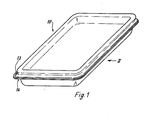
- FIGS. 1 to 4 shows a tableware part for microwave ovens, which is provided with the reference number 10 as a whole.
- the crockery part 10 is made entirely of plastic and bowl-shaped and has the overall shape of a bowl, as shown in Figures 1 and 2.
- the dish part 10 consists of an inner shell 11 and an outer shell 12.
- both the inner shell 11 and the outer shell 12 are in the upper region of the dish part 10 with peripheral and laterally projecting edge webs 13 or 14 provided.
- the inner shell 11 and outer shell 12 are firmly connected to one another, preferably by means of a weld provided with the reference number 15.
- the inner shell 11 and outer shell 12 could, however, also be glued to one another by a suitable adhesive.
- the inner shell 11 and outer shell 12 are at a distance from one another, so that an intermediate space 16 is formed between the two shells 11 and 12 and is filled with air.
- Both the inner shell 11 and the outer shell 12 are each formed as one-piece, deep-drawn plastic parts.
- the arrangement of support cams 17 may be expedient to increase the overall rigidity and the overall stability, which are preferably drawn into the outer shell 12 and extend to the inner shell 11 and in the area of contact with the inner shell 11 by this in turn Welding are firmly connected.
- the overall strength of the crockery part 10 can be increased considerably, despite the minimal use of material and the associated small wall thickness for the inner shell 11 and outer shell 12.
- the space 16 present between the inner shell 11 and the outer shell 12 and filled with air serves as an insulating layer, which on the one hand leads to the fact that food contained in such a dish part 10 can be heated comparatively quickly in a microwave oven, since heat losses through the walls of the dish part 10 are relatively small and, on the other hand, due to the insulating effect also has the positive effect that the heated food is kept warm for a relatively long time.
- FIG. 5 shows an exemplary embodiment of the invention in which the dish part 10 again has the shape of a bowl.
- the inner shell 11 is provided with a circumferential, projecting edge web 13 and the outer shell with a corresponding edge web 14. Both edge webs 13 and 14 are in turn welded together.
- support cams 17 can be provided to increase the overall stability.
- the tableware part 10 is also made of plastic Lid 18 closable.
- the upper support edge 19 of the tableware part 10 is tapered on the outside towards the bottom of the tableware part 10, and the shape of the lid 18 is chosen accordingly. With this construction, an airtight closure of the crockery part 10 by means of the lid 18, which is desirable per se, is achieved.
- the tableware part 10 is partially provided in the region of its support edge 19 with a trough 20 widening towards the interior of the tableware part 10 and the lid 18 with a vent hole 21.
- the vent hole 21 opens into a recess 22 of the edge web 13 of the inner shell 11 when the cover 18 is attached.
- the airtight closed position shown in FIG. 6 for the tableware part 10 is desirable when freezing food.
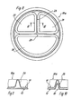
- FIG. 8 shows a crockery part 10a for a microwave oven, which is designed as a menu plate in a departure from the forms shown so far.
- This crockery part 10a has a circular basic shape and is provided with separating webs 28 and 29 in its bowl-shaped interior. These compartments 28 and 29 separate various compartments 30 and 31 within the menu plate.
- the separating webs 28 or 29 may only be provided in the area of the inner shell, but it does exist also the possibility of providing the respective outer shell of the crockery part 10a in the area of the separating webs 28 or 29 dt corresponding indentations 32, which makes Figure 10 clear.
- the inner shell 11 may have a different contour shape than the outer shell 12, only in the region of the edge webs 13 and 14 to be joined together, the inner shell 11 and outer shell 12 must be congruent. There is also the possibility of designing the inner shell 11 differently in color from the outer shell 12.
- the inner shell 11 like the outer shell 12, retains a certain elasticity, so that without there is also the possibility of clamping a metal plate or the like into such a dish part 10 or 10a, which, when used in a microwave oven, is used to achieve a browning effect for meat dishes or the like.
- the inner shell 11 and the outer shell 12 can also each be produced in one piece as injection molded parts, in order to maintain the advantages already mentioned several times, care must be taken that these injection molded parts are relatively thin-walled.
- the covers 18 shown in FIGS. 5 to 7 can of course, like the dishes 10, have a two-shell structure, so that the specified insulating effect also applies to the respective covers 18.
- the recess 22 of the edge web 13 shown in FIG. 5 preferably runs over the entire edge web 13, which has the advantage that, regardless of the position in which the cover 18 is placed, the vent hole 21 always opens into the circumferential recess 22. This means that when the cover 18 is put on, there is no need to pay attention to the position of the depression 22.
Landscapes
- Engineering & Computer Science (AREA)
- Mechanical Engineering (AREA)
- Food Science & Technology (AREA)
- Life Sciences & Earth Sciences (AREA)
- Cookers (AREA)
- Table Devices Or Equipment (AREA)
- Compositions Of Macromolecular Compounds (AREA)
- Electric Ovens (AREA)
Abstract
Ein aus Kunststoff gefertigtes, schalenförmiges Geschirrteil (10) für Mikrowellenherde soll bei geringstem Materialeinsatz und damit auch geringen Herstellkosten so gestaltet werden, daß es eine hohe Eigensteifigkeit und Stabilität aufweist und somit im Haushalt als Dauergeschirr verwendbar ist. Zu diesem Zweck weist das Geschirrteil (10) einen zweischaligen Aufbau aus einer Innenschale (11) und einer Außenschale (12) auf, die im Bereich von umlaufenden und seitlich vorstehenden Randstegen (13, 14) durch eine Verschweißung (15) fest miteinander verbunden sind. Zwischen den beiden Schalen (11) und (12) ist ein Zwischenraum (16) vorhanden. Durch den zweischaligen Aufbau wird bei geringen Gesamtkosten eine hohe Stabilität und eine gute Isolierwirkung erzielt.A bowl-shaped crockery part (10) made of plastic for microwave ovens should be designed with the least use of material and thus also low manufacturing costs so that it has a high degree of rigidity and stability and can therefore be used in the household as permanent dishes. For this purpose, the crockery part (10) has a two-shell structure consisting of an inner shell (11) and an outer shell (12) which are firmly connected to one another in the area of peripheral and laterally projecting edge webs (13, 14) by welding (15) . There is an intermediate space (16) between the two shells (11) and (12). Due to the double-shell structure, high stability and good insulation are achieved at low overall costs.
Description
Die vorliegende Erfindung bezieht sich auf ein aus Kunststoff gefertigtes, schalenförmiges Geschirrteil für Mikrowellenherde, beispielsweise in Form einer Schüssel, eines Menütellers od. dgl.The present invention relates to a plastic dish-shaped dish for microwave ovens, for example in the form of a bowl, a menu plate or the like.
Mikrowellenherde erfreuen sich insbesondere im Haushaltsbereich zunehmender Beliebtheit, insbesondere deshalb, weil in Mikrowellenherden Speisen in kürzester Zeit gegart oder aufgetaut und bei Bedarf erhitzt werden können.Microwave ovens are enjoying increasing popularity, particularly in the household sector, in particular because meals can be cooked or thawed in a short time in microwave ovens and heated if necessary.
Entsprechend besteht ein zunehmender Bedarf an geeigneten Geschirr für Mikrowellenherde.Accordingly, there is an increasing need for suitable dishes for microwave ovens.
Grundsätzlich sind zwei Geschirrarten für Mikrowellenherde bekannt.Basically, two types of dishes for microwave ovens are known.
Einerseits gibt es einfache, aus Kunststoff gefertigte und äußerst dünnwandige Geschirrteile, die als Einwegverpackungen benutzt werden. In derartigen Geschirrteilen werden meist komplett vorbereitete und vorgegarte Speisen über den Handel angeboten und vom Endverbraucher in dem betreffenden Geschirr im Mikrowellenherd lediglich erhitzt. Nach dem Verzehr der Speisen wird dieses Geschirr weggeworfen.On the one hand, there are simple, extremely thin-walled dishes made of plastic that are used as disposable packaging. Completely prepared and pre-cooked dishes are usually offered through the trade in such crockery parts and are only heated by the end user in the relevant crockery in the microwave oven. After eating the dishes, these dishes are thrown away.
Für die dauernde Benutzung im Mikrowellenherd sind Geschirrteile aus Kunststoff bekannt, die verhältnismäßig massiv und demzufolge auch entsprechend stabil sind. Derartige Geschirrteile werden meist im Spritzgießverfahren hergestellt oder aus entsprechend hochwertigem Kunststoff gepreßt.For permanent use in the microwave oven, plastic tableware parts are known which are relatively solid and consequently correspondingly stable. Such crockery parts are usually made by injection molding or pressed from corresponding high-quality plastic.
Die letztgenannte Kategorie von entsprechendem Geschirr ist vergleichsweise teuer, was einerseits daran liegt, daß der zum Einsatz kommende Kunststoff relativ hochwertig und demzufolge sehr teuer ist und andererseits auch damit zusammenhängt, daß die Herstellung derartigen Geschirres in entsprechenden Formen recht zeit- und damit kostenaufwendig ist.The latter category of corresponding tableware is comparatively expensive, which is partly due to the fact that the plastic used is relatively high quality and therefore very expensive and secondly it is related to the fact that the production of such tableware in corresponding forms is quite time-consuming and therefore costly.
Der vorliegenden Erfindung liegt die Aufgabe zugrunde, ein Geschirrteil der gattungsgemäßen Art zu schaffen, welches bei geringstem Materialeinsatz und insgesamt geringen Herstellkosten eine Steifigkeit und Stabilität aufweist, die eine Dauerverwendung ohne weiteres gestattet.The present invention has for its object to provide a tableware part of the generic type, which has the least amount of material and low manufacturing costs, a rigidity and stability that allows long-term use without further ado.
Diese Aufgabe wird erfindungsgemäß gelöst durch einen zweischaligen Aufbau aus einer Innenschale und einer Außenschale, wobei Innen- und Außenschale unter Lufteinschluß mit Abstand zueinander angeordnet und im Bereich von umlaufenden und seitlich vorstehenden Randstegen miteinander verschweißt oder verklebt sind.This object is achieved according to the invention by a double-shell structure comprising an inner shell and an outer shell, the inner and outer shells being arranged at a distance from one another with the inclusion of air and being welded or glued to one another in the region of peripheral and laterally projecting edge webs.
Durch den zweischaligen Aufbau des Geschirrteiles und die feste Verbindung der beiden Schalen im Bereich von ohnehin stabilisierenden Randstegen wird bei geringstem Materialeinsatz ein Höchstmaß an Steifigkeit und Festigkeit erreicht, so daß ein derartiges Geschirrteil ohne weiteres einer Dauerverwendung im Haushalt gewachsen ist. Aufgrund des geringen Materialeinsatzes ist das Geschirrteil selbst vergleichsweise kostengünstig und bietet darüber hinaus noch eine Reihe von Vorteilen, die aufgrund seines zweischaligen Aufbaues erzielt werden.Due to the two-shell structure of the crockery part and the firm connection of the two shells in the area of the already stabilizing edge webs, the greatest possible rigidity and strength are achieved with the least use of materials speed reached, so that such a piece of crockery can easily cope with continuous use in the household. Due to the low use of materials, the tableware part itself is comparatively inexpensive and also offers a number of advantages which are achieved due to its double-shell structure.
So besteht einer dieser Vorteile darin, daß zur Erwärmung von Speisen in einem derartigen Geschirrteil weniger Energie benötigt wird als bislang, da die zwischen Innen-und Außenschale eingeschlossene Luft als Isolierschicht wirkt. Der gleiche Isoliereffekt bringt den weiteren Vorteil mit sich, daß erwärmte Speisen länger warm gehalten werden können.One of these advantages is that less energy is required to heat dishes in such a piece of crockery than before, since the air enclosed between the inner and outer shells acts as an insulating layer. The same insulating effect has the further advantage that heated dishes can be kept warm for longer.
Aufgrund des zweischaligen Aufbaues bestehen auch hinsichtlich der reinen Formgestaltung erheblich mehr Möglichkeiten als dies bislang der Fall war, da Innen- und Außenschale weitestgehend unabhängig voneinander gestaltet werden können. Es ist lediglich dafür zu sorgen, daß Innen- und Außenschale im Bereich ihrer Randstege praktisch formgleich sind, um hier eine dichte und feste Verbindung erzielen zu können.Due to the double-shell structure, there are also considerably more possibilities with regard to the pure shape than was previously the case, since the inner and outer shell can be designed largely independently of one another. It is only necessary to ensure that the inner and outer shells are practically identical in shape in the region of their edge webs in order to be able to achieve a tight and firm connection here.
Innen- und Außenschale können auch ohne weiteres farblich unterschiedlich gestaltet sein.The inner and outer shell can easily be designed in different colors.
Aufgrund der schon angesprochenen Steifigkeit und Festigkeit ist ein derartiges Geschirrteil auch ohne weiteres spülmaschinenfest und entspricht somit allen Anforderungen, die an modernes Geschirr im Haushalt gestellt werden.Due to the rigidity and strength already mentioned, such a tableware part is also dishwasher-safe and thus meets all the requirements placed on modern tableware in the household.
Weitere Merkmale der Erfindung sind Gegenstand von Unteransprüchen.Further features of the invention are the subject of sub claims.
In den beigefügten Zeichnungen sind Ausführungsbeispiele der Erfindung dargestellt, die im folgenden näher beschrieben werden.In the accompanying drawings, embodiments of the invention are shown, which are described in more detail below.
Im einzelnen zeigen:
- Fig. 1 eine perspektivische Darstellung eines Geschirrteiles für Mikrowellenherde in Form einer Schüssel,
- Fig. 2 eine Ansicht des Geschirrteiles in Richtung des Pfeiles II in Fig. 1,
- Fig. 3 einen stark vergrößert dargestellten Längsschnitt durch das Geschirrteil gemäß Figuren 1 und 2 im Bodenbereich,
- Fig. 4 einen Teilschnitt durch das Geschirrteil gemäß den Figuren 1 und 2 im Randbereich,
- Fig. 5 einen der Figur 4 entsprechenden Teilschnitt bei einem Geschirrteil mit aufgesetztem Deckel nach einem weiteren Ausführungsbeispiel der Erfindung,
- Fig. 6 + 7 der Fig. 5 entsprechende Teilschnitte durch ein weiteres Geschirrteil mit Deckel,
- Fig. 8 eine Draufsicht auf ein Geschirrteil nach einem weiteren Ausführungsbeispiel der Erfindung,
- Fig. 9 einen Teilschnitt nach der Linie IX-IX in Fig. 8,
- Fig. 10 einen der Figur 9 entsprechenden Teilschnitt durch ein Geschirrteil nach einem weiteren Ausführungsbeispiel der Erfindung.
- 1 is a perspective view of a dish part for microwave ovens in the form of a bowl,
- 2 is a view of the dishes in the direction of arrow II in Fig. 1,
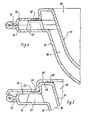
- 3 shows a greatly enlarged longitudinal section through the crockery part according to FIGS. 1 and 2 in the bottom area,
- 4 shows a partial section through the crockery part according to FIGS. 1 and 2 in the edge area,
- 5 shows a partial section corresponding to FIG. 4 for a tableware part with a lid attached according to a further exemplary embodiment of the invention,
- 6 + 7 of FIG. 5 corresponding partial sections through a further tableware part with a lid,
- 8 is a plan view of a tableware part according to a further embodiment of the invention,
- 9 is a partial section along the line IX-IX in Fig. 8,
- 10 shows a partial section corresponding to FIG. 9 through a tableware part according to a further exemplary embodiment of the invention.
Das in den Figuren 1 bis 4 gezeigte Ausführungsbeispiel der Erfindung zeigt ein Geschirrteil für Mikrowellenherde, welches insgesamt mit dem Bezugszeichen 10 versehen ist. Das Geschirrteil 10 ist insgesamt aus Kunststoff gefertigt und schalenförmig gestaltet und weist insgesamt die Form einer Schüssel auf, was die Figuren 1 und 2 deutlich machen.The exemplary embodiment of the invention shown in FIGS. 1 to 4 shows a tableware part for microwave ovens, which is provided with the
Es sei allerdings an dieser Stelle schon darauf hingewiesen, daß der Erfindungsgedanke nicht gebunden ist an die Form des Geschirrteiles selbst. Darauf wird im Zusammenhang mit dem Ausführungsbeispiel gemäß Figur 8 noch näher eingegangen.At this point, however, it should already be pointed out that the idea of the invention is not tied to the shape of the dish part itself. This will be discussed in more detail in connection with the exemplary embodiment according to FIG.
Wie insbesondere die Figuren 3 und 4 deutlich machen, besteht das Geschirrteil 10 aus einer Innenschale 11 und einer Außenschale 12. Wie deutlich erkennbar ist, sind sowohl die Innenschale 11 wie auch die Außenschale 12 im oberen Bereich des Geschirrteiles 10 mit umlaufenden und seitlich vorstehenden Randstegen 13 bzw. 14 versehen. Im Bereich dieser umlaufenden Randstege 13 bzw. 14 sind Innenschale 11 und Außenschale 12 fest miteinander verbunden, und zwar vorzugsweise durch eine mit dem Bezugszeichen 15 versehene Verschweißung. Alternativ hierzu könnten Innenschale 11 und Außenschale 12 allerdings auch durch einen geeigneten Kleber miteinander verklebt sein.As in particular FIGS. 3 and 4 make clear, the
Ansonsten weisen Innenschale 11 und Außenschale 12 einen Abstand zueinander auf, so daß zwischen den beiden Schalen 11 und 12 ein Zwischenraum 16 gebildet ist, der mit Luft ausgefüllt ist.Otherwise, the
Sowohl die Innenschale 11 wie auch die Außenschale 12 sind jeweils als einstückige, tiefgezogene Kunststoff teile ausgebildet.Both the
Je nach Größe der Gesamtgrundfläche des Geschirrteiles 10 kann zur Erhöhung der Gesamtsteifigkeit und der Gesamtstabilität die Anordnung von Stütznocken 17 sinnvoll sein, die vorzugsweise in die Außenschale 12 eingezogen sind und sich bis zur Innenschale 11 erstrecken und im Berührungsbereich zur Innenschale 11 mit dieser wiederum durch eine Verschweißung fest verbunden sind. Durch diese Stütznocken 17 kann die Gesamtfestigkeit des Geschirrteiles 10 trotz geringsten Materialeinsatzes und damit einhergehender geringer Wandstärke für Innenschale 11 und Außenschale 12 beträchtlich erhöht werden.Depending on the size of the total base area of the
Der zwischen der Innenschale 11 und der Außenschale 12 vorhandene und mit Luft gefüllte Zwischenraum 16 dient als Isolierschicht, die einerseits dazu führt, daß in einem derartigen Geschirrteil 10 befindliche Speise in einem Mikrowellenherd vergleichsweise rasch erwärmt werden kann, da Wärmeverluste durch die Wandungen des Geschirrteiles 10 relativ gering sind und andererseits aufgrund des Isoliereffektes auch noch den positiven Effekt mit sich bringt, daß die erwärmte Speise relativ lange warm gehalten wird.The
In Figur 5 ist ein Ausführungsbeispiel der Erfindung gezeigt bei dem das Geschirrteil 10 wiederum die Form einer Schüssel aufweist. Auch hier ist die Innenschale 11 mit einem umlaufenden, vorstehenden Randsteg 13 und die Außenschale mit einem korrespondierenden Randsteg 14 versehen. Beide Randstege 13 und 14 sind wiederum miteinander verschweißt. Auch hier können Stütznocken 17 zur Erhöhung der Gesamtstabilität vorgesehen sein.FIG. 5 shows an exemplary embodiment of the invention in which the
Das Geschirrteil 10 ist beim Ausführungsbeispiel gemäß Figur 5 mittels eines ebenfalls aus Kunststoff gefertigten Deckels 18 verschließbar. Der obere Auflagerand 19 des Geschirrteiles 10 ist außenseitig zur Bodenseite des Geschirrteiles 10 hin gesehen konisch verjüngt, entsprechend ist die Form des Deckels 18 gewählt. Durch diese Konstruktion wird ein an sich wünschenswerter, luftdichter Abschluß des Geschirrteiles 10 mittels des Deckels 18 erreicht.In the exemplary embodiment according to FIG. 5, the
Soll nun im verschlossenen Geschirrteil 10 eine darin befindliche Speise im Mikrowellenherd erhitzt werden so ist es erforderlich, daß Luft aus dem Geschirrteil 10 entweichen kann.If a food contained therein is now to be heated in the microwave oven in the closed
Dies ist beim Ausführungsbeispiel gemäß Figur 5 dadurch erreicht worden,daß eine Art "Überdruckventil" einerseits in den Auflagerand 19 des Geschirrteiles 10 und andererseits in den Deckel 18 integriert worden ist. Wie Figur 5 deutlich macht, ist das Geschirrteil 10 im Bereich seines Auflagerandes 19 partiell mit einer sich zum Inneren des Geschirrteiles 10 hin erweiternden Mulde 20 und der Deckel 18 mit einer Entlüftungsbohrung 21 versehen. Die Entlüftungsbohrung 21 mündet bei aufgesetztem Deckel 18 in eine Vertiefung 22 des Randsteges 13 der Innenschale 11.In the exemplary embodiment according to FIG. 5, this has been achieved in that a type of “pressure relief valve” has been integrated on the one hand into the
Bildet 'sich nun bei der Erwärmung einer Speise im Inneren des durch den Deckel 18 verschlossenen Geschirrteiles 10 ein gewisser Überdruck, so wird dieser durch die Mulde 20, die Vertiefung 22 und die Entlüftungsbohrung 21 entweichen können, bedingt durch die Elastizität des Auflagerandes 19 und/oder des Deckels 18.If a certain overpressure now forms when a food is heated inside the
Bei dem in den Figuren 6 und 7 gezeigten Ausführungsbeispiel der Neuerung ist der obere Auflagerand 19 des Geschirrteiles 10 außenseitig mit zwei gegeneinander versetzten Stufen 23 und 24 versehen. Ein Deckel 18 ist im Bereich seines Schließrandes 25 innenseitig mit entsprechend abgesetzten Vorsprüngen 26 und 27 ausgestattet.In the embodiment shown in FIGS. 6 and 7 The innovation of the
Ist der Deckel 18, wie in Figur 6 gezeigt, vollständig auf den Auflagerand 19 des Geschirrteiles 10 aufgedrückt, so ergibt sich ein luftdichter Abschluß des Innenraumes des Geschirrteiles 10. Wird hingegen der Deckel 18 im Bereich der ersten Stufe 23 auf den Auflagerand 19 des Geschirrteiles 10 aufgesetzt, wie in Figur 7 dargestellt, so ergibt sich ein luftdurchlässiger Verschluß des Geschirrteiles 10. Dies bedeutet, daß in dieser einstufig gerasteten Schließstellung im Geschirrteil 10 befindliche Speisen im Mikrowellenherd erhitzt werden können, ohne daß es zu einem unerwünschten Überdruck im Inneren des Geschirrteiles 10 kommen kann.If the
Die in Figur 6 gezeigte, luftdichte Schließstellung für das Geschirrteil 10 ist beim Einfrieren von Speisen wünschenswert.The airtight closed position shown in FIG. 6 for the
In Figur 8 ist ein Geschirrteil 10a für einen Mikrowellenherd gezeigt, welches in Abweichung von den bisher dargestellten Formen als Menüteller ausgebildet ist. Dieses Geschirrteil 10a weist eine kreisrunde Grundform auf und ist in seinem schalenförmigen Inneren mit Trennstegen 28 bzw. 29 versehen. Durch diese Trennstege 28 und 29 werden innerhalb des Menütellers verschiedene Fächer 30 bzw. 31 abgetrennt.FIG. 8 shows a crockery part 10a for a microwave oven, which is designed as a menu plate in a departure from the forms shown so far. This crockery part 10a has a circular basic shape and is provided with separating
Wie nun Figur 9 deutlich macht, können die Trennstege 28 oder 29 ausschließlich im Bereich der Innenschale vorgesehen sein, es besteht aber
auch die Möglichkeit, die jeweilige Außenschale des Geschirrteiles 10a im Bereich der Trennstege 28 oder 29 dt entsprechenden Einziehungen 32 zu versehen, was Figur 10 deutlich macht. Zusätzlich besteht die Möglichkeit, in dem Bereich zwischen den Trennstegen 28 oder 29 und entsprechenden Einziehungen 32 der Außenschale 12 Stütznocken 17 vorzusehen und diese mit der Innenschale 11 durch Verschweißen zu verbinden.As FIG. 9 now makes clear, the separating
also the possibility of providing the respective outer shell of the crockery part 10a in the area of the separating
Die vorstehenden Ausführungen machen deutlich, daß der erfindungsgemäße Aufbau eines erfindungsgemäßen Geschirrteiles 10 oder 10a aus zwei Schalen vielfältige Gestaltungsmöglichkeiten mit sich bringt, die einerseits der Erhöhung der Eigensteifigkeit, der Stabilität und der Festigkeit des Geschirrteiles 10 oder 10a selbst dienen können und die andererseits aber auch die Möglichkeiteröffnen, ein derartiges Geschirrteil 10 oder 10a hinsichtlich der reinen Formgestaltung äußerst vielseitig beeinflussen zu können.The above statements make it clear that the construction of a
So kann beispielsweise die Innenschale 11 durchaus einen anderen Konturenverlauf aufweisen wie die Außenschale 12, lediglich im Bereich der miteinander zu verbindenden Randstege 13 und 14 müssen Innenschale 11 und Außenschale 12 kongruent sein. Ebenso besteht die Möglichkeit die Innenschale 11 gegenüber der Außenschale 12 farblich abweichend zu gestalten.For example, the
Bei aller Stabilität des gesamten Geschirrteiles 10 oder 10a behält die Innenschale 11 ebenso wie die Außenschale 12 in sich gesehen eine gewisse Elastizität, so daß ohne weiteres die Möglichkeit besteht in ein derartiges Geschirrteil 10 oder 10a eine Metallplatte od. dgl. einzuklemmen, die bei Benutzung in einem Mikrowellenherd der Erzielung eines Bräunungseffektes für Fleischspeisen od. dgl. dient.With all the stability of the
Im Rahmen der vorliegenden Erfindung können die Innenschale 11 und die Außenschale 12 jeweils auch einstückig als Spritzgießteile hergestellt sein, wobei zur Beibehaltung der schon mehrfach erwähnten Vorteile darauf zu achten ist, daß diese Spritzgießteile verhältnismäßig dünnwandig sind.In the context of the present invention, the
Die in den Figuren 5 bis 7 gezeigten Deckel 18 können selbstverständlich ebenso wie die Geschirrteile 10 einen zweischaligen Aufbau aufweisen, so daß der angegebene Isoliereffekt auch für die jeweiligen Deckel 18 gilt.The
Die in Figur 5 dargestellte Vertiefung 22 des Randsteges 13 läuft vorzugsweise über den gesamten Randsteg 13 um, was den Vorteil mit sich bringt, daß unabhängig davon, in welcher Lage der Deckel 18 aufgesetzt wird, die Entlüftungsbohrung 21 immer in die umlaufende Vertiefung 22 einmündet. Dies bedeutet, daß beim Aufsetzen des Deckels 18 nicht darauf geachtet werden muß, an welcher Stelle sich die Vertiefung-22 befindet.The
- 10 +10 +
- 10a Geschirrteil10a tableware
- 11 Innenschale11 inner shell
- 12 Außenschale12 outer shell
- 13 Randstege13 bridges
- 14 "14 "
- 15 Verschweißung15 welding
- 16 Zwischenraum16 space
- 17 Stütznocken17 support cams
- 18 Deckel18 lid
- 19 Auflagerand19 support edge
- 20 Mulde20 trough
- 21 Entlüftungsbohrung21 vent hole
- 22 Vertiefung22 deepening
- 23 Stufe23 level
- 24 "24 "
- 25 Schließrand25 closing edge
- 26 Vorsprung26 head start
- 27 "27 "
- 28 Trennstege28 dividers
- 29 "29 "
- 30 Fächer30 compartments
- 31 "31 "
- 32 Einziehungen32 recoveries
Claims (14)
Priority Applications (1)
| Application Number | Priority Date | Filing Date | Title |
|---|---|---|---|
| AT87105168T ATE56601T1 (en) | 1986-04-19 | 1987-04-08 | PLASTIC BOWL-SHAPED Crockery FOR MICROWAVE OVEN. |
Applications Claiming Priority (2)
| Application Number | Priority Date | Filing Date | Title |
|---|---|---|---|
| DE3613298 | 1986-04-19 | ||
| DE19863613298 DE3613298A1 (en) | 1986-04-19 | 1986-04-19 | PLASTIC-BASED DISHWARE FOR MICROWAVE OVENS, MADE OF PLASTIC |
Publications (2)
| Publication Number | Publication Date |
|---|---|
| EP0242701A1 true EP0242701A1 (en) | 1987-10-28 |
| EP0242701B1 EP0242701B1 (en) | 1990-09-19 |
Family
ID=6299087
Family Applications (1)
| Application Number | Title | Priority Date | Filing Date |
|---|---|---|---|
| EP87105168A Expired - Lifetime EP0242701B1 (en) | 1986-04-19 | 1987-04-08 | Plastic dish-like piece of crockery for a microwave oven |
Country Status (12)
| Country | Link |
|---|---|
| US (1) | US4847459A (en) |
| EP (1) | EP0242701B1 (en) |
| JP (1) | JPS6311115A (en) |
| AR (1) | AR244973A1 (en) |
| AT (1) | ATE56601T1 (en) |
| AU (1) | AU7172287A (en) |
| BR (1) | BR8701851A (en) |
| CA (1) | CA1270909A (en) |
| DE (1) | DE3613298A1 (en) |
| DK (1) | DK177387A (en) |
| ES (1) | ES2017660B3 (en) |
| NO (1) | NO871558L (en) |
Cited By (5)
| Publication number | Priority date | Publication date | Assignee | Title |
|---|---|---|---|---|
| FR2638957A1 (en) * | 1988-11-17 | 1990-05-18 | Corning France | Combined containers for cooking or (and) defrosting foodstuffs, particularly in a microwave oven |
| EP0461549A1 (en) * | 1990-06-08 | 1991-12-18 | Sierra Housewares, Inc. | Chill-retention food service tray |
| EP0509664A1 (en) * | 1991-04-16 | 1992-10-21 | Viskase Corporation | Microwavable container |
| WO2000021849A1 (en) * | 1998-10-12 | 2000-04-20 | Kevin William Joseph Clarke | Thermally insulated microwave cooking container |
| EP3174816A4 (en) * | 2014-08-01 | 2018-03-07 | Graphic Packaging International, Inc. | Microwave packaging |
Families Citing this family (41)
| Publication number | Priority date | Publication date | Assignee | Title |
|---|---|---|---|---|
| DE8911682U1 (en) * | 1989-09-30 | 1989-11-16 | Aveco Gmbh, 7888 Rheinfelden, De | |
| DE9002855U1 (en) * | 1990-03-10 | 1990-05-31 | Hagro-Grosskuechenausstattungen Gmbh, 4358 Haltern, De | |
| US4998000A (en) * | 1990-05-02 | 1991-03-05 | Halloran Edward J | Closure device for microwavable vessels |
| US5012061A (en) * | 1990-07-09 | 1991-04-30 | Lesser Emmett H | Microwave safety lid |
| US5300748A (en) * | 1992-07-27 | 1994-04-05 | Mobil Oil Corporation | Recyclable microwavable container with a hinged removable outer shell |
| DE4324070A1 (en) * | 1992-07-31 | 1994-02-03 | Ewald Jassmann | Piece of crockery for storing and serving food - has matching rims round edge of both container and lid which interfit |
| US5628453A (en) * | 1996-01-16 | 1997-05-13 | Packaging Resources, Inc. | Cup with thermally insulated side wall |
| JP2963664B2 (en) * | 1996-11-22 | 1999-10-18 | 日本酸素株式会社 | Synthetic resin insulated container and synthetic resin insulated lid |
| WO2000041605A1 (en) | 1999-01-16 | 2000-07-20 | Jong Do Peter Park | Cooking utensil |
| US6191393B1 (en) | 1999-01-16 | 2001-02-20 | Jong Do Peter Park | Cooking utensil and manufacturing method therefor |
| US6257401B1 (en) | 1999-05-14 | 2001-07-10 | Pactiv Corporation | Vented container with handles and embossment |
| USD443205S1 (en) | 1999-05-14 | 2001-06-05 | Tenneco Packaging Inc. | Bottom for a container |
| USD433334S (en) * | 1999-05-27 | 2000-11-07 | Pactiv Corporation | Cover for a container |
| USD432914S (en) * | 1999-05-27 | 2000-10-31 | Pactiv Corporation | Bottom for a container |
| US7017775B2 (en) | 1999-08-10 | 2006-03-28 | S.C. Johnson & Son, Inc. | Container lid including venting and denesting features, and container having such a lid |
| USD439160S1 (en) | 1999-09-03 | 2001-03-20 | Tenneco Packaging Inc. | Container |
| USD444382S1 (en) | 1999-10-06 | 2001-07-03 | Pactiv Corporation | Cover for a container |
| US6729472B2 (en) * | 2001-01-12 | 2004-05-04 | Wki Holding Company, Inc. | Container assembly and nesting set thereof |
| USD489941S1 (en) | 2001-05-01 | 2004-05-18 | Pactiv Corporation | Plate having condiment wells |
| USD481260S1 (en) | 2001-05-01 | 2003-10-28 | Pactiv Corporation | Plate having condiment wells |
| US7172072B2 (en) * | 2001-05-01 | 2007-02-06 | Pactiv Corporation | Compartment plates having themes and method for manufacturing and packaging the same |
| USD481592S1 (en) | 2001-05-01 | 2003-11-04 | Pactiv Corporation | Plate having condiment wells |
| US7013618B2 (en) | 2001-05-01 | 2006-03-21 | Pactiv Corporation | Compartment plates having themes and method for manufacturing and packaging the same |
| USD483998S1 (en) | 2001-05-01 | 2003-12-23 | Pactiv Corporation | Plate having condiment wells |
| US7104030B2 (en) * | 2001-05-01 | 2006-09-12 | Pactiv Corporation | Compartment plates having themes and method for manufacturing and packaging the same |
| USD480922S1 (en) | 2001-05-01 | 2003-10-21 | Pactiv Corporation | Plate having condiment wells |
| US6649891B1 (en) | 2001-09-25 | 2003-11-18 | Anne Kitko | Microwavable food storage container |
| KR100436263B1 (en) | 2002-03-26 | 2004-06-16 | 삼성전자주식회사 | Cooking Container and Microwave Oven Having the Cooking Container |
| USD485731S1 (en) | 2003-02-19 | 2004-01-27 | Pactiv Corporation | Plate having two compartments |
| WO2004083049A1 (en) * | 2003-03-13 | 2004-09-30 | Fort James Corporation | Microwaveable food storage container with freshness indicator and steam vent |
| US20080073366A1 (en) * | 2006-08-22 | 2008-03-27 | Backaert Dimitri M C J | Fast freeze container and seal |
| US20090200324A1 (en) * | 2008-02-07 | 2009-08-13 | Extron International Limited | Foodware Set That Includes A Multifunction Cover-Base Assembly |
| EP2165937A1 (en) * | 2008-09-23 | 2010-03-24 | Nestec S.A. | Bicoloured aluminium container and process for producing said container |
| SG181852A1 (en) * | 2009-12-30 | 2012-07-30 | Heinz Co H J | Multi-temperature and multi-texture frozen food microwave heating tray |
| US8783490B2 (en) * | 2010-04-23 | 2014-07-22 | Zuna Enterprises, Llc | Composite microwave and oven safe food container system |
| IL217430A0 (en) * | 2012-01-08 | 2012-02-29 | Oren Shadmi | Wonder boxes to keep the food and drink cold and hot |
| USD745800S1 (en) | 2014-05-30 | 2015-12-22 | Ontel Products Corporation | Microwaveable egg maker |
| HK1199365A2 (en) * | 2015-02-16 | 2015-06-26 | 大塑膠工業 香港 有限公司 | A blow-molded case and a reinforcing structure thereof |
| US20170202389A1 (en) * | 2016-01-14 | 2017-07-20 | Iris Ohyama Inc. | Cooking apparatus |
| US11292654B2 (en) * | 2019-06-20 | 2022-04-05 | Sonoco Development, Inc. | Venting system for ovenable containers |
| USD950321S1 (en) * | 2020-02-12 | 2022-05-03 | Dart Industries Inc. | Storage container |
Citations (6)
| Publication number | Priority date | Publication date | Assignee | Title |
|---|---|---|---|---|
| US2928567A (en) * | 1957-12-10 | 1960-03-15 | Joseph Davis Plastics Co | Utensil |
| US4081646A (en) * | 1976-03-15 | 1978-03-28 | Teckton, Inc. | Device for microwave cooking |
| FR2447174A1 (en) * | 1979-01-24 | 1980-08-22 | Cidelcem | Thermally insulating food dish with cover - has triple walled cavity construction with inner cavity filled with paraffin and outer cavity evacuated |
| US4533061A (en) * | 1979-09-17 | 1985-08-06 | American Hospital Supply Corporation | Food tray and lid with sealed panels and method of forming same |
| US4549672A (en) * | 1985-01-10 | 1985-10-29 | Isaac Rinkewich | Double-wall container |
| EP0169780A1 (en) * | 1984-07-20 | 1986-01-29 | CIDELCEM Société Anonyme dite | Food container |
Family Cites Families (9)
| Publication number | Priority date | Publication date | Assignee | Title |
|---|---|---|---|---|
| US1927255A (en) * | 1933-07-14 | 1933-09-19 | William A Brown | Metallic container |
| DE1554625A1 (en) * | 1966-02-17 | 1970-01-29 | Austria Email Ag | Double-walled cooking, roasting and baking vessel and process for making the same |
| US3745290A (en) * | 1972-03-01 | 1973-07-10 | Gen Electric | Inductively heatable utensils or vessels for heating,serving and storing food |
| US3979572A (en) * | 1974-10-29 | 1976-09-07 | Mitsubishi Denki Kabushiki Kaisha | Induction heating apparatus |
| US4478349A (en) * | 1979-01-12 | 1984-10-23 | Mirro Corporation | Insulated dish and lid for microwave cooking |
| US4314638A (en) * | 1981-04-02 | 1982-02-09 | International Paper Company | Shipping container designed to prevent can damage due to chime ride |
| US4413167A (en) * | 1982-01-11 | 1983-11-01 | Raytheon Company | Microwave egg cooker |
| US4486640A (en) * | 1982-11-01 | 1984-12-04 | Raytheon Company | Cooker/baker utensil for microwave oven |
| US4663506A (en) * | 1986-07-30 | 1987-05-05 | Raytheon Company | Microwave cake and bread maker |
-
1986
- 1986-04-19 DE DE19863613298 patent/DE3613298A1/en active Granted
-
1987
- 1987-04-08 EP EP87105168A patent/EP0242701B1/en not_active Expired - Lifetime
- 1987-04-08 AT AT87105168T patent/ATE56601T1/en not_active IP Right Cessation
- 1987-04-08 ES ES87105168T patent/ES2017660B3/en not_active Expired - Lifetime
- 1987-04-13 NO NO871558A patent/NO871558L/en unknown
- 1987-04-15 BR BR8701851A patent/BR8701851A/en unknown
- 1987-04-15 AR AR87307315A patent/AR244973A1/en active
- 1987-04-16 CA CA000534972A patent/CA1270909A/en not_active Expired - Fee Related
- 1987-04-16 AU AU71722/87A patent/AU7172287A/en not_active Abandoned
- 1987-04-17 JP JP62093419A patent/JPS6311115A/en active Pending
- 1987-04-20 US US07/039,897 patent/US4847459A/en not_active Expired - Fee Related
- 1987-05-05 DK DK177387A patent/DK177387A/en not_active Application Discontinuation
Patent Citations (6)
| Publication number | Priority date | Publication date | Assignee | Title |
|---|---|---|---|---|
| US2928567A (en) * | 1957-12-10 | 1960-03-15 | Joseph Davis Plastics Co | Utensil |
| US4081646A (en) * | 1976-03-15 | 1978-03-28 | Teckton, Inc. | Device for microwave cooking |
| FR2447174A1 (en) * | 1979-01-24 | 1980-08-22 | Cidelcem | Thermally insulating food dish with cover - has triple walled cavity construction with inner cavity filled with paraffin and outer cavity evacuated |
| US4533061A (en) * | 1979-09-17 | 1985-08-06 | American Hospital Supply Corporation | Food tray and lid with sealed panels and method of forming same |
| EP0169780A1 (en) * | 1984-07-20 | 1986-01-29 | CIDELCEM Société Anonyme dite | Food container |
| US4549672A (en) * | 1985-01-10 | 1985-10-29 | Isaac Rinkewich | Double-wall container |
Cited By (8)
| Publication number | Priority date | Publication date | Assignee | Title |
|---|---|---|---|---|
| FR2638957A1 (en) * | 1988-11-17 | 1990-05-18 | Corning France | Combined containers for cooking or (and) defrosting foodstuffs, particularly in a microwave oven |
| EP0461549A1 (en) * | 1990-06-08 | 1991-12-18 | Sierra Housewares, Inc. | Chill-retention food service tray |
| EP0509664A1 (en) * | 1991-04-16 | 1992-10-21 | Viskase Corporation | Microwavable container |
| WO2000021849A1 (en) * | 1998-10-12 | 2000-04-20 | Kevin William Joseph Clarke | Thermally insulated microwave cooking container |
| AU740703B2 (en) * | 1998-10-12 | 2001-11-15 | Kevin William Joseph Clarke | Thermally insulated microwave cooking container |
| US6609627B1 (en) | 1998-10-12 | 2003-08-26 | Kevin William Joseph Clarke | Thermally insulated microwave cooking container |
| EP3174816A4 (en) * | 2014-08-01 | 2018-03-07 | Graphic Packaging International, Inc. | Microwave packaging |
| US9938067B2 (en) | 2014-08-01 | 2018-04-10 | Graphic Packaging International, Llc | Microwave packaging |
Also Published As
| Publication number | Publication date |
|---|---|
| EP0242701B1 (en) | 1990-09-19 |
| CA1270909A (en) | 1990-06-26 |
| AR244973A1 (en) | 1993-12-30 |
| JPS6311115A (en) | 1988-01-18 |
| DK177387D0 (en) | 1987-05-05 |
| NO871558D0 (en) | 1987-04-13 |
| DK177387A (en) | 1987-10-20 |
| NO871558L (en) | 1987-10-20 |
| DE3613298A1 (en) | 1987-10-22 |
| ATE56601T1 (en) | 1990-10-15 |
| DE3613298C2 (en) | 1988-03-17 |
| AU7172287A (en) | 1987-10-22 |
| BR8701851A (en) | 1988-01-26 |
| ES2017660B3 (en) | 1991-03-01 |
| US4847459A (en) | 1989-07-11 |
Similar Documents
| Publication | Publication Date | Title |
|---|---|---|
| EP0242701B1 (en) | Plastic dish-like piece of crockery for a microwave oven | |
| DE3215174C2 (en) | ||
| DE4121706C2 (en) | Apparatus for cooking, serving and storing food and the like | |
| DE4012379A1 (en) | SPLASH-PROTECTED Raised Fume Hood | |
| EP0511938A2 (en) | Metal hollow-ware | |
| DE3309534C2 (en) | Vessels, in particular for cooking food | |
| DE2745643A1 (en) | PLATE ARRANGEMENT | |
| DE19856494C2 (en) | Tray for packaging meat portions or similar foods | |
| DE19962897C1 (en) | Paint bowl for paint box, with projecting edge, groove, push button and downward extensions | |
| DE2206747A1 (en) | EQUIPMENT FOR STORING, SERVING AND DISCUSSING FOOD - ESPECIALLY BUTTER | |
| DE102005047663A1 (en) | Spray guard for a cooking pan has circular surround to fit into pan wall and a cover having an opening to permit stirring of the food | |
| DE29880162U1 (en) | Food product comprising a waffle containing a food core | |
| WO2002081990A1 (en) | Storage container for refrigerators | |
| DE102008053181A1 (en) | Cooking vessel for cooking food, has flange that is made of plastic such as silicone plastic and comprises two regions, where one of regions comprises larger distance to center point of cover than other region | |
| DE2103179C3 (en) | Plastic containers | |
| DE3643282C2 (en) | ||
| DE19847186C2 (en) | Multi-part microwave dishes | |
| DE7635978U1 (en) | Cream cheese | |
| DE8416662U1 (en) | Container | |
| EP0474980A1 (en) | Thermally insulated vessel | |
| DE19609507A1 (en) | Two component plastics container | |
| DE2123054B2 (en) | Rectangular tray for packing meat, fish or poultry | |
| DE7500238U (en) | Cake Tin | |
| DE7130535U (en) | Screw lids for vacuum jugs and similar vessels | |
| DE7418747U (en) | Cooking device, in particular fondue device |
Legal Events
| Date | Code | Title | Description |
|---|---|---|---|
| PUAI | Public reference made under article 153(3) epc to a published international application that has entered the european phase |
Free format text: ORIGINAL CODE: 0009012 |
|
| AK | Designated contracting states |
Kind code of ref document: A1 Designated state(s): AT BE CH ES FR GB IT LI LU NL SE |
|
| 17P | Request for examination filed |
Effective date: 19871209 |
|
| 17Q | First examination report despatched |
Effective date: 19890210 |
|
| ITF | It: translation for a ep patent filed |
Owner name: DE DOMINICIS & MAYER S.R.L. |
|
| GRAA | (expected) grant |
Free format text: ORIGINAL CODE: 0009210 |
|
| AK | Designated contracting states |
Kind code of ref document: B1 Designated state(s): AT BE CH ES FR GB IT LI LU NL SE |
|
| REF | Corresponds to: |
Ref document number: 56601 Country of ref document: AT Date of ref document: 19901015 Kind code of ref document: T |
|
| ET | Fr: translation filed | ||
| GBT | Gb: translation of ep patent filed (gb section 77(6)(a)/1977) | ||
| PG25 | Lapsed in a contracting state [announced via postgrant information from national office to epo] |
Ref country code: GB Effective date: 19910408 Ref country code: AT Effective date: 19910408 |
|
| PG25 | Lapsed in a contracting state [announced via postgrant information from national office to epo] |
Ref country code: SE Effective date: 19910409 |
|
| PGFP | Annual fee paid to national office [announced via postgrant information from national office to epo] |
Ref country code: ES Payment date: 19910416 Year of fee payment: 5 |
|
| PG25 | Lapsed in a contracting state [announced via postgrant information from national office to epo] |
Ref country code: LU Free format text: LAPSE BECAUSE OF NON-PAYMENT OF DUE FEES Effective date: 19910430 Ref country code: LI Effective date: 19910430 Ref country code: CH Effective date: 19910430 Ref country code: BE Effective date: 19910430 |
|
| PLBE | No opposition filed within time limit |
Free format text: ORIGINAL CODE: 0009261 |
|
| STAA | Information on the status of an ep patent application or granted ep patent |
Free format text: STATUS: NO OPPOSITION FILED WITHIN TIME LIMIT |
|
| 26N | No opposition filed | ||
| BERE | Be: lapsed |
Owner name: MELITTA-WERKE BENTZ & SOHN Effective date: 19910430 |
|
| PG25 | Lapsed in a contracting state [announced via postgrant information from national office to epo] |
Ref country code: NL Effective date: 19911101 |
|
| GBPC | Gb: european patent ceased through non-payment of renewal fee | ||
| NLV4 | Nl: lapsed or anulled due to non-payment of the annual fee | ||
| PG25 | Lapsed in a contracting state [announced via postgrant information from national office to epo] |
Ref country code: FR Effective date: 19911230 |
|
| REG | Reference to a national code |
Ref country code: CH Ref legal event code: PL |
|
| REG | Reference to a national code |
Ref country code: FR Ref legal event code: ST |
|
| PG25 | Lapsed in a contracting state [announced via postgrant information from national office to epo] |
Ref country code: ES Free format text: LAPSE BECAUSE OF NON-PAYMENT OF DUE FEES Effective date: 19920409 |
|
| EUG | Se: european patent has lapsed |
Ref document number: 87105168.6 Effective date: 19911108 |
|
| REG | Reference to a national code |
Ref country code: ES Ref legal event code: FD2A Effective date: 19990405 |
|
| PG25 | Lapsed in a contracting state [announced via postgrant information from national office to epo] |
Ref country code: IT Free format text: LAPSE BECAUSE OF NON-PAYMENT OF DUE FEES;WARNING: LAPSES OF ITALIAN PATENTS WITH EFFECTIVE DATE BEFORE 2007 MAY HAVE OCCURRED AT ANY TIME BEFORE 2007. THE CORRECT EFFECTIVE DATE MAY BE DIFFERENT FROM THE ONE RECORDED. Effective date: 20050408 |