EP0242985A2 - Preformable catheter assembly and stylet therefor - Google Patents
Preformable catheter assembly and stylet therefor Download PDFInfo
- Publication number
- EP0242985A2 EP0242985A2 EP87302366A EP87302366A EP0242985A2 EP 0242985 A2 EP0242985 A2 EP 0242985A2 EP 87302366 A EP87302366 A EP 87302366A EP 87302366 A EP87302366 A EP 87302366A EP 0242985 A2 EP0242985 A2 EP 0242985A2
- Authority
- EP
- European Patent Office
- Prior art keywords
- stylet
- catheter
- wire
- cover
- handle
- Prior art date
- Legal status (The legal status is an assumption and is not a legal conclusion. Google has not performed a legal analysis and makes no representation as to the accuracy of the status listed.)
- Granted
Links
Images
Classifications
-
- A—HUMAN NECESSITIES
- A61—MEDICAL OR VETERINARY SCIENCE; HYGIENE
- A61M—DEVICES FOR INTRODUCING MEDIA INTO, OR ONTO, THE BODY; DEVICES FOR TRANSDUCING BODY MEDIA OR FOR TAKING MEDIA FROM THE BODY; DEVICES FOR PRODUCING OR ENDING SLEEP OR STUPOR
- A61M25/00—Catheters; Hollow probes
- A61M25/0021—Catheters; Hollow probes characterised by the form of the tubing
- A61M25/0041—Catheters; Hollow probes characterised by the form of the tubing pre-formed, e.g. specially adapted to fit with the anatomy of body channels
-
- A—HUMAN NECESSITIES
- A61—MEDICAL OR VETERINARY SCIENCE; HYGIENE
- A61M—DEVICES FOR INTRODUCING MEDIA INTO, OR ONTO, THE BODY; DEVICES FOR TRANSDUCING BODY MEDIA OR FOR TAKING MEDIA FROM THE BODY; DEVICES FOR PRODUCING OR ENDING SLEEP OR STUPOR
- A61M25/00—Catheters; Hollow probes
- A61M25/01—Introducing, guiding, advancing, emplacing or holding catheters
- A61M25/09—Guide wires
- A61M25/09016—Guide wires with mandrils
- A61M25/09025—Guide wires with mandrils with sliding mandrils
Definitions
- This invention relates to a preformable catheter assembly and a malleable stylet therefor.
- Cardiopulmonary bypass vascular catheters for example, left atrial or left heart vent and left ventricular vent catheters, are used to drain fluid from the left ventricle to prevent excessive pressure build-up in the left heart portion during bypass surgery.
- Such catheters are often inserted with the aid of a stylet and may be preformable to a desired profile.
- the left atrial vent catheter may be inserted through the right superior pulmonary vein, left atrium, and mitral valve, and into the left ventricle.
- the left ventricular vent catheter may be introduced directly into the left ventricle through the ventricle wall. After insertion, the stylet is removed from the catheter and the catheter is connected to an extracorporeal system that includes artificial heart and lung apparatus.
- PVC polyvinyl chloride
- conventional PVC catheters have become less desirable because they become relatively rigid and less flexible at the lower temperatures making the catheter more difficult to manipulate during insertion and removal from the patient.
- silicone rubber which is soft and supple, and these characteristics are substantially unaffected by the low temperatures encountered during surgery. Because silicone rubber catheters are soft and supple, there is less chance of damage to the patient during insertion and removal of the catheter as well as during the operation.
- Stylets have been formed of closely coiled stainless steel wire so that the stylet has a substantially larger diameter than that of a straight wire in order to more nearly fill the catheter lumen. In this way, the stylet can have a sufficiently large diameter relative to the catheter lumen so as to produce -a catheter having sufficiently good handling and shaping characteristics, and yet have a high malleability due to the small diameter of wire used in the coiled stylet.
- coiled stainless steel wire stylets are relatively heavy and expensive compared to straight wire stylets.
- Catheters having a malleable wire embedded in the sidewall of the catheter have been used to allow shaping of the catheter prior to insertion but the suppleness or flexibility of such catheters while in the heart and vessels of the patient are limited by the presence of the wire which cannot be removed from the catheter.
- Non-malleable plastic such as nylon or high density polyethylene rods have been proposed as stiffeners but are generally limited to catheters that do not require manual preshaping.
- the invention also provides a novel malleable stylet.
- a stylet for a catheter comprising a malleable wire having a cover of plastics material.
- a cover increases the effective diameter of the stylet without substantially affecting the malleability of the wire.
- the cross-sectional area of the cover may be greater than the cross-sectional area of the wire.
- the cover is a tubular extrusion or sleeve into which the wire is inserted; the distal end of the sleeve is closed by, for example, heat sealing.
- the wire is of aluminium and the cover is of polypropylene.
- the outer diameter of the stylet is preferably at least 60% of the diameter of the catheter lumen.
- the stylet may have a handle which, with the cover, completely encases the wire.
- the invention also provides a catheter assembly including the stylet aforesaid and a catheter of silicone rubber.
- Releasable latching means may be provided between a handle of the stylet and the proximal end of the catheter to hold the stylet in the catheter during the insertion procedure.
- the latching means preferably comprise hook means on the handle which releasably engage a flange of a connector for the catheter.
- the hook means may be a flexible arm moulded integrally with said handle.
- a cardiopulmonary bypass vascular catheter assembly including a left atrial vent catheter 12 and stylet 31.
- Catheter 12 includes a flexible tube 16 which is preferably formed of an elastomer such as silicone rubber, so that the tube is soft and supple.
- Tube 16 is provided with a conical or radially outwardly flaring funnel connector 18 at the proximal end of the tube which receives one end 20 of a double-ended tube connector 22.
- the lumen 23 of the tube 16 is closed at the distal end by a catheter tip 24 having a smoothly rounded outer surface.
- Adjacent the distal end of tube 16 are a plurality of eyes or openings 26 extending through the sidewall of the tube 16.
- the funnel connector 18 may be formed of a suitable material such as silicone rubber and is connected to the tube 16 by an adhesive or bonding agent.
- the end 20 has tapered portions tapering inwardly in the distal direction and is connected to the funnel connector 18 by a tight frictional engagement fit.
- the tip 24 is also preferably of silicone rubber and is fixed to the distal end of tube 16 by a suitable bonding agent, for example, a silicone adhesive.
- the tube connector 22 has a proximal end 28 which has portions tapering inwardly in the proximal direction and is adapted for : ' . frictional connection with tubing (not shown), such as tubing of an extracorporeal artificial heart-lung system.
- the connector 22 has a bore 30 extending through it which is in fluid communication with catheter lumen 23.
- the stylet 31 comprises an inner stylet rod or wire 32 extending within an outer covering 34 which may be a separately formed sleeve.
- the proximal ends of the stylet wire 32 and the covering 34 are fixed to and within a stylet handle 36 which may be formed or moulded of a suitable plastic such as polyethylene or the like.
- the stylet wire 32 and covering 34 may be insert moulded in handle 36 during the moulding process.
- the stylet is shown as having a pair of crimps 38 with the proximal end of tube 16 extending over the distal crimp. The proximal end of covering 34 is thus closed to the atmosphere.
- a spherical distal end tip 40 is provided at the distal end of covering 34.
- the rounded tip 40 may be formed by melt forming the distal end of sleeve 34. Tip 40 closes the distal end of sleeve 34 to atmosphere and ensures that the distal end of wire 32 does not pierce the catheter 12. Thus, the entire wire 32 in the construction shown is completely enclosed by the covering 34 and handle 36, the covering completely enclosing the free surface of the wire while the handle covers the proximal end portion.
- Handle 36 has a distal portion 42 which slidingly fits into the proximal end 28 of tube connector 22, and a proximally extending integral fixed arm 44.
- the handle has a pivotal latching arm 45 connected intermediate its ends to the arm 44 by an integral,resilient connection 46.
- the arm 45 has a latch 47 at the distal end that co-operates with an integral annular flange 48 on the tube connector 22.
- Arm 45 has an end portion 49 extending proximally from the resilient connection 46.
- the stylet handle 36 is shown in Figures 1 and 4 in the latched condition with the latch 47 engaging the distal side of flange 48 to prevent proximal movement of the stylet 14 relative to the catheter 12.
- the stylet 14 When in the latched condition, the stylet 14 extends to the distal region of catheter lumen 23 as shown in Figure 1. In this way, the stylet 14 is maintained in its desired fully inserted condition in catheter 12 so that the catheter and stylet can be inserted into a patient without the stylet moving longitudinally relative to the catheter and the distal end of catheter 12 bending excessively.
- the proximal end 49 of the latch arm 45 may be moved toward the arm 44, such as by pinching end 49 and arm 44, to unlatch the latch 47 from flange 48. This allows the stylet 14 to be withdrawn proximally from the catheter 12.
- Stylet wire 32 is formed of a suitable malleable metal, such as aluminium or stainless steel, preferably, it is formed of solid aluminium.
- the covering 34 is preferably a plastic material and polypropylene is especially preferable because of its desirable characteristic of being readily slidable without undue force from its fully inserted condition as shown in Figures 1 and 4 to a fully removed condition ( Figure 3).
- Covering 34 may be made of other materials such as high density polyethylene, polytetrafluoroethylene, fluorinated ethylene propylene or polyacetal in some catheters.
- the stylet covering 34 may be a sleeve of plastic material such as an extruded sleeve of polypropylene, alternatively, the covering 34 may be a coating applied in liquid form'and hardened or applied in any other suitable manner. Where an extruded sleeve is used, the diameter of the sleeve should be slightly larger than the wire to permit insertion of the wire into the sleeve during manufacture.
- the surgeon may manually curve or bend the assembly into a desired configuration for insertion, tip first, into the patient.
- catheter 12 Once catheter 12 is in its desired location, the stylet 31 is unlatched from connector 22, and withdrawn from catheter 12 and the tube connector 22 while maintaining the catheter tip 24 and openings 26 in position.
- Catheter 12 being pliable and formed of a soft material, such as silicone rubber, is substantially inert to the body and there is less chance of damage to the patient than when catheters of more rigid materials are employed.
- the malleable stylet 31 can be readily bent by the surgeon into the desired shape with the pliable catheter tube 16 taking on any shape that is assumed by the stylet wire. Since the stylet 31 is capable of being easily deformed and maintains its deformity permanently or until reshaped, the supple catheter 12 surrounding the stylet is, of course, similarly deformed or shaped and remains deformed by the stylet. At the same time, the stylet 31 causes the assembly 10 to be sufficiently stiff so as to be inserted or worked into its desired final location within the patient without an undesirable amount of effort.
- the rounded tip 40 of stylet 31 aids in ensuring that the soft silicone rubber catheter tube 16 is not inadvertently pierced by the stylet wire 32 during typical insertion procedures. Since the stylet wire is completely enclosed by the covering 34 and the handle 36, blood cannot contact the metal wire.
- the stylet readily slides on the silicone rubber sidewalls of lumen 23 substantially without sticking and even though the stylet and catheter may be curved or bent. This allows the stylet assembly 14 to be easily removed from catheter 14 while maintaining the catheter 12 in place within the patient.
- the diameter of the stylet is effectively increased without increasing the size of wire 32 and thereby decreasing the malleability of the stylet.
- the stylet should be slightly less in diameter than the catheter lumen so that no undue effort is required for removal.
- a stylet of relatively large diameter, such as stylet 31 good bending and insertion control characteristics with less flexing of the catheter relative to the stylet are obtained.
- a catheter and stylet assembly included a silicone rubber catheter having a lumen with a diameter of about 3.05mm and a stylet having an outer diameter of about 2.54mm.
- the stylet had a solid aluminium wire having an outer diameter of about 1.57mm and a covering sleeve cut from extruded polypropylene tubing having an inner diameter of about 1.70mm and an outer diameter of about 2.54mm, these being nominal values.
- the outer diameter of the wire is slightly less than the inner diameter of the covering to allow insertion of the wire into the covering during manufacture of the stylet.
- the overall outer diameter of the stylet is about 83% of the diameter of the catheter lumen and provides good handling characteristics.
- the above stylet may be used with a large catheter such as one having a lumen with a diameter of about 4.12mm. In this case, the diameter of the stylet is still more than one-half of that of the diameter of the larger catheter lumen and functions satisfactorily.
- the catheter and stylet assembly can be made identical to assembly 10 except that the catheter holes will not generally be placed as far from the distal end of the catheter as they are in a left atrial vent catheter.
- the catheter tube material may be of a suitable thermoplastic polyurethane, latex rubber or the like instead of the preferred silicone rubber.
Landscapes
- Health & Medical Sciences (AREA)
- Life Sciences & Earth Sciences (AREA)
- Biophysics (AREA)
- Pulmonology (AREA)
- Engineering & Computer Science (AREA)
- Anesthesiology (AREA)
- Biomedical Technology (AREA)
- Heart & Thoracic Surgery (AREA)
- Hematology (AREA)
- Animal Behavior & Ethology (AREA)
- General Health & Medical Sciences (AREA)
- Public Health (AREA)
- Veterinary Medicine (AREA)
- Materials For Medical Uses (AREA)
- Media Introduction/Drainage Providing Device (AREA)
Abstract
Description
- This invention relates to a preformable catheter assembly and a malleable stylet therefor.
- Cardiopulmonary bypass vascular catheters, for example, left atrial or left heart vent and left ventricular vent catheters, are used to drain fluid from the left ventricle to prevent excessive pressure build-up in the left heart portion during bypass surgery. Such catheters are often inserted with the aid of a stylet and may be preformable to a desired profile. The left atrial vent catheter may be inserted through the right superior pulmonary vein, left atrium, and mitral valve, and into the left ventricle. The left ventricular vent catheter may be introduced directly into the left ventricle through the ventricle wall. After insertion, the stylet is removed from the catheter and the catheter is connected to an extracorporeal system that includes artificial heart and lung apparatus.
- Hitherto many such catheters have been made of polyvinyl chloride (PVC) for use with a rigid plastic stylet or with a malleable wire embedded in a sidewall of the catheter. However, since heart surgery is now being performed at relatively low temperatures, conventional PVC catheters have become less desirable because they become relatively rigid and less flexible at the lower temperatures making the catheter more difficult to manipulate during insertion and removal from the patient. Also, with relatively stiff catheters there is greater risk of damage to the heart during the operation. For this reason, such catheters have more recently been made of silicone rubber which is soft and supple, and these characteristics are substantially unaffected by the low temperatures encountered during surgery. Because silicone rubber catheters are soft and supple, there is less chance of damage to the patient during insertion and removal of the catheter as well as during the operation.
- If the diameter of the stylet is excessively small, it may kink and bend in the catheter making the manual preshaping of the catheter less accurate or controllable. Stylets have been formed of closely coiled stainless steel wire so that the stylet has a substantially larger diameter than that of a straight wire in order to more nearly fill the catheter lumen. In this way, the stylet can have a sufficiently large diameter relative to the catheter lumen so as to produce -a catheter having sufficiently good handling and shaping characteristics, and yet have a high malleability due to the small diameter of wire used in the coiled stylet. However, coiled stainless steel wire stylets are relatively heavy and expensive compared to straight wire stylets.
- Catheters having a malleable wire embedded in the sidewall of the catheter have been used to allow shaping of the catheter prior to insertion but the suppleness or flexibility of such catheters while in the heart and vessels of the patient are limited by the presence of the wire which cannot be removed from the catheter. Non-malleable plastic such as nylon or high density polyethylene rods have been proposed as stiffeners but are generally limited to catheters that do not require manual preshaping.
- It is therefore an object of the present invention to provide a malleable catheter assembly having a removable stylet which overcomes the aforementioned problems. The invention also provides a novel malleable stylet.
- According to the invention there is provided a stylet for a catheter and comprising a malleable wire having a cover of plastics material. Such a cover increases the effective diameter of the stylet without substantially affecting the malleability of the wire. The cross-sectional area of the cover may be greater than the cross-sectional area of the wire. Preferably the cover is a tubular extrusion or sleeve into which the wire is inserted; the distal end of the sleeve is closed by, for example, heat sealing.
- In a preferred embodiment the wire is of aluminium and the cover is of polypropylene. The outer diameter of the stylet is preferably at least 60% of the diameter of the catheter lumen.
- The stylet may have a handle which, with the cover, completely encases the wire.
- The invention also provides a catheter assembly including the stylet aforesaid and a catheter of silicone rubber. Releasable latching means may be provided between a handle of the stylet and the proximal end of the catheter to hold the stylet in the catheter during the insertion procedure. The latching means preferably comprise hook means on the handle which releasably engage a flange of a connector for the catheter. The hook means may be a flexible arm moulded integrally with said handle.
- Other features of the invention will be apparent from the following description of a preferred embodiment shown by way of example only in the accompanying drawing in which:- \
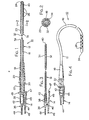
- Figure 1 is a longitudinal cross-section through a cardiopulmonary left atrial vent catheter assembly in accordance with the present invention;
- Figure 2 is an enlarged cross-section taken along line 2-2 of Figure 1;
- Figure 3 is a longitudinal cross-section through the stylet of Figure 1; and
- Figure 4 is a side elevation on a slightly reduced scale of the catheter assembly of Figure 1 but after it has been manually formed into a curved configuration.
- Referring now to the drawings, and particularly to Figures 1 and 2, there is shown a cardiopulmonary bypass vascular catheter assembly including a left
atrial vent catheter 12 andstylet 31. -
Catheter 12 includes aflexible tube 16 which is preferably formed of an elastomer such as silicone rubber, so that the tube is soft and supple. Tube 16 is provided with a conical or radially outwardly flaringfunnel connector 18 at the proximal end of the tube which receives oneend 20 of a double-ended tube connector 22. Thelumen 23 of thetube 16 is closed at the distal end by acatheter tip 24 having a smoothly rounded outer surface. Adjacent the distal end oftube 16 are a plurality of eyes oropenings 26 extending through the sidewall of thetube 16. Thefunnel connector 18 may be formed of a suitable material such as silicone rubber and is connected to thetube 16 by an adhesive or bonding agent. Theend 20 has tapered portions tapering inwardly in the distal direction and is connected to thefunnel connector 18 by a tight frictional engagement fit. Thetip 24 is also preferably of silicone rubber and is fixed to the distal end oftube 16 by a suitable bonding agent, for example, a silicone adhesive. Thetube connector 22 has aproximal end 28 which has portions tapering inwardly in the proximal direction and is adapted for :'. frictional connection with tubing (not shown), such as tubing of an extracorporeal artificial heart-lung system. Theconnector 22 has abore 30 extending through it which is in fluid communication withcatheter lumen 23. - As seen also in Figure 3, the
stylet 31 comprises an inner stylet rod orwire 32 extending within anouter covering 34 which may be a separately formed sleeve. The proximal ends of thestylet wire 32 and thecovering 34 are fixed to and within astylet handle 36 which may be formed or moulded of a suitable plastic such as polyethylene or the like. Thestylet wire 32 and covering 34 may be insert moulded inhandle 36 during the moulding process. The stylet is shown as having a pair ofcrimps 38 with the proximal end oftube 16 extending over the distal crimp. The proximal end of covering 34 is thus closed to the atmosphere. A sphericaldistal end tip 40 is provided at the distal end of covering 34. Therounded tip 40 may be formed by melt forming the distal end ofsleeve 34.Tip 40 closes the distal end ofsleeve 34 to atmosphere and ensures that the distal end ofwire 32 does not pierce thecatheter 12. Thus, theentire wire 32 in the construction shown is completely enclosed by thecovering 34 and handle 36, the covering completely enclosing the free surface of the wire while the handle covers the proximal end portion. -
Handle 36 has adistal portion 42 which slidingly fits into theproximal end 28 oftube connector 22, and a proximally extending integral fixedarm 44. The handle has apivotal latching arm 45 connected intermediate its ends to thearm 44 by an integral,resilient connection 46. Thearm 45 has alatch 47 at the distal end that co-operates with an integralannular flange 48 on thetube connector 22.Arm 45 has anend portion 49 extending proximally from theresilient connection 46. Thestylet handle 36 is shown in Figures 1 and 4 in the latched condition with thelatch 47 engaging the distal side offlange 48 to prevent proximal movement of thestylet 14 relative to thecatheter 12. When in the latched condition, thestylet 14 extends to the distal region ofcatheter lumen 23 as shown in Figure 1. In this way, thestylet 14 is maintained in its desired fully inserted condition incatheter 12 so that the catheter and stylet can be inserted into a patient without the stylet moving longitudinally relative to the catheter and the distal end ofcatheter 12 bending excessively. When it is desired to remove the stylet from thecatheter 12, theproximal end 49 of thelatch arm 45 may be moved toward thearm 44, such as by pinchingend 49 andarm 44, to unlatch thelatch 47 fromflange 48. This allows thestylet 14 to be withdrawn proximally from thecatheter 12. -
Stylet wire 32 is formed of a suitable malleable metal, such as aluminium or stainless steel, preferably, it is formed of solid aluminium. The covering 34 is preferably a plastic material and polypropylene is especially preferable because of its desirable characteristic of being readily slidable without undue force from its fully inserted condition as shown in Figures 1 and 4 to a fully removed condition (Figure 3). Covering 34 may be made of other materials such as high density polyethylene, polytetrafluoroethylene, fluorinated ethylene propylene or polyacetal in some catheters. - The stylet covering 34 may be a sleeve of plastic material such as an extruded sleeve of polypropylene, alternatively, the covering 34 may be a coating applied in liquid form'and hardened or applied in any other suitable manner. Where an extruded sleeve is used, the diameter of the sleeve should be slightly larger than the wire to permit insertion of the wire into the sleeve during manufacture.
- In use, with the stylet in place in
catheter 12 as shown in Figure 1, the surgeon may manually curve or bend the assembly into a desired configuration for insertion, tip first, into the patient. Oncecatheter 12 is in its desired location, thestylet 31 is unlatched fromconnector 22, and withdrawn fromcatheter 12 and thetube connector 22 while maintaining thecatheter tip 24 andopenings 26 in position. -
Catheter 12, being pliable and formed of a soft material, such as silicone rubber, is substantially inert to the body and there is less chance of damage to the patient than when catheters of more rigid materials are employed. Themalleable stylet 31 can be readily bent by the surgeon into the desired shape with thepliable catheter tube 16 taking on any shape that is assumed by the stylet wire. Since thestylet 31 is capable of being easily deformed and maintains its deformity permanently or until reshaped, thesupple catheter 12 surrounding the stylet is, of course, similarly deformed or shaped and remains deformed by the stylet. At the same time, thestylet 31 causes theassembly 10 to be sufficiently stiff so as to be inserted or worked into its desired final location within the patient without an undesirable amount of effort. As previously mentioned, the roundedtip 40 ofstylet 31 aids in ensuring that the soft siliconerubber catheter tube 16 is not inadvertently pierced by thestylet wire 32 during typical insertion procedures. Since the stylet wire is completely enclosed by the covering 34 and thehandle 36, blood cannot contact the metal wire. - It has been found that when the covering 34 is of polypropylene, the stylet readily slides on the silicone rubber sidewalls of
lumen 23 substantially without sticking and even though the stylet and catheter may be curved or bent. This allows thestylet assembly 14 to be easily removed fromcatheter 14 while maintaining thecatheter 12 in place within the patient. By employing the covering 34, the diameter of the stylet is effectively increased without increasing the size ofwire 32 and thereby decreasing the malleability of the stylet. The stylet should be slightly less in diameter than the catheter lumen so that no undue effort is required for removal. By employing a stylet of relatively large diameter, such asstylet 31, good bending and insertion control characteristics with less flexing of the catheter relative to the stylet are obtained. - In the preferred embodiment a catheter and stylet assembly included a silicone rubber catheter having a lumen with a diameter of about 3.05mm and a stylet having an outer diameter of about 2.54mm. The stylet had a solid aluminium wire having an outer diameter of about 1.57mm and a covering sleeve cut from extruded polypropylene tubing having an inner diameter of about 1.70mm and an outer diameter of about 2.54mm, these being nominal values. The outer diameter of the wire is slightly less than the inner diameter of the covering to allow insertion of the wire into the covering during manufacture of the stylet. Thus, while the outer diameter of such wire was only about one-half of that of the catheter lumen, the overall outer diameter of the stylet, including the polypropylene covering, is about 83% of the diameter of the catheter lumen and provides good handling characteristics. About one-third of the diametral thickness of the stylet, is provided by the cover, and the cross-sectional area of cover is greater than that of wire. The above stylet may be used with a large catheter such as one having a lumen with a diameter of about 4.12mm. In this case, the diameter of the stylet is still more than one-half of that of the diameter of the larger catheter lumen and functions satisfactorily.
- In the case of a left ventricular vent catheter, the catheter and stylet assembly can be made identical to
assembly 10 except that the catheter holes will not generally be placed as far from the distal end of the catheter as they are in a left atrial vent catheter. Also, depending upon the use to which the catheter is to be put, the catheter tube material may be of a suitable thermoplastic polyurethane, latex rubber or the like instead of the preferred silicone rubber. It should be understood that although the invention has been described with reference to the illustrated embodiment, modifications thereto may be made without departing from the scope of the invention which is limited only by the claims appended hereto.
Claims (9)
Priority Applications (1)
| Application Number | Priority Date | Filing Date | Title |
|---|---|---|---|
| AT87302366T ATE72405T1 (en) | 1986-03-26 | 1987-03-19 | DEFORMABLE CATHETER ASSEMBLY AND ASSOCIATED STYLUS. |
Applications Claiming Priority (2)
| Application Number | Priority Date | Filing Date | Title |
|---|---|---|---|
| US84439786A | 1986-03-26 | 1986-03-26 | |
| US844397 | 1986-03-26 |
Publications (3)
| Publication Number | Publication Date |
|---|---|
| EP0242985A2 true EP0242985A2 (en) | 1987-10-28 |
| EP0242985A3 EP0242985A3 (en) | 1989-06-14 |
| EP0242985B1 EP0242985B1 (en) | 1992-02-05 |
Family
ID=25292621
Family Applications (1)
| Application Number | Title | Priority Date | Filing Date |
|---|---|---|---|
| EP87302366A Expired - Lifetime EP0242985B1 (en) | 1986-03-26 | 1987-03-19 | Preformable catheter assembly and stylet therefor |
Country Status (7)
| Country | Link |
|---|---|
| EP (1) | EP0242985B1 (en) |
| JP (1) | JPS62243566A (en) |
| AT (1) | ATE72405T1 (en) |
| AU (1) | AU590914B2 (en) |
| CA (1) | CA1287540C (en) |
| DE (1) | DE3776587D1 (en) |
| ES (1) | ES2028864T3 (en) |
Cited By (5)
| Publication number | Priority date | Publication date | Assignee | Title |
|---|---|---|---|---|
| WO1994013350A1 (en) * | 1992-12-14 | 1994-06-23 | Schneider (Usa) Inc. | Tracking guidewire |
| WO1994017743A1 (en) * | 1993-02-11 | 1994-08-18 | Harry Hodgkins | Embryo replacement catheter |
| US20120316542A1 (en) * | 2008-03-27 | 2012-12-13 | Terumo Kabushiki Kaisha | Medical device manufacturing method and medical device assembly |
| US9149604B2 (en) | 2003-11-07 | 2015-10-06 | Kaneka Corporation | Aspiration catheter |
| US10252023B2 (en) | 2013-01-11 | 2019-04-09 | C. R. Bard, Inc. | Curved catheter and methods for making same |
Families Citing this family (4)
| Publication number | Priority date | Publication date | Assignee | Title |
|---|---|---|---|---|
| US20060162731A1 (en) * | 2004-11-16 | 2006-07-27 | Pulmonx | Pulmonary occlusal stent delivery catheter, loading system and methods of use |
| CN100548410C (en) * | 2005-03-04 | 2009-10-14 | 导管治疗有限公司 | Modular catheter and the conduit tube component that comprises this handle |
| DE602007004718D1 (en) | 2006-03-31 | 2010-03-25 | Bard Inc C R | Catheter with arched transition area |
| AU2008202483B2 (en) | 2007-06-15 | 2011-07-14 | Cathrx Ltd | A deflectable stylet |
Citations (6)
| Publication number | Priority date | Publication date | Assignee | Title |
|---|---|---|---|---|
| US3419010A (en) * | 1966-01-17 | 1968-12-31 | Cordis Corp | Catheter |
| US3923066A (en) * | 1974-01-03 | 1975-12-02 | Rhone Poulenc Sa | Device for holding a catheter in an extended condition |
| US3957055A (en) * | 1974-09-23 | 1976-05-18 | Linder Gerald S | Catheter guide |
| US4185639A (en) * | 1978-03-27 | 1980-01-29 | Linder Gerald S | Adjustable stop for endotracheal tube guide |
| DE3100546A1 (en) * | 1981-01-10 | 1982-07-29 | B. Braun Melsungen Ag, 3508 Melsungen | Gastrointestinal probe |
| US4504268A (en) * | 1981-11-10 | 1985-03-12 | Intermedicate Gmbh | Stiffening core for a catheter tube |
Family Cites Families (3)
| Publication number | Priority date | Publication date | Assignee | Title |
|---|---|---|---|---|
| US3996939A (en) * | 1975-07-22 | 1976-12-14 | National Catheter Corporation | Intubation stylets |
| US4348632A (en) * | 1980-09-15 | 1982-09-07 | International Business Machines Corporation | Servosystem operating about noise component error signal |
| JPS59151969A (en) * | 1983-02-21 | 1984-08-30 | テルモ株式会社 | Cathetel |
-
1987
- 1987-03-12 JP JP62057872A patent/JPS62243566A/en active Pending
- 1987-03-18 AU AU70130/87A patent/AU590914B2/en not_active Ceased
- 1987-03-19 DE DE8787302366T patent/DE3776587D1/en not_active Expired - Lifetime
- 1987-03-19 AT AT87302366T patent/ATE72405T1/en not_active IP Right Cessation
- 1987-03-19 EP EP87302366A patent/EP0242985B1/en not_active Expired - Lifetime
- 1987-03-19 ES ES198787302366T patent/ES2028864T3/en not_active Expired - Lifetime
- 1987-03-19 CA CA000532520A patent/CA1287540C/en not_active Expired - Lifetime
Patent Citations (6)
| Publication number | Priority date | Publication date | Assignee | Title |
|---|---|---|---|---|
| US3419010A (en) * | 1966-01-17 | 1968-12-31 | Cordis Corp | Catheter |
| US3923066A (en) * | 1974-01-03 | 1975-12-02 | Rhone Poulenc Sa | Device for holding a catheter in an extended condition |
| US3957055A (en) * | 1974-09-23 | 1976-05-18 | Linder Gerald S | Catheter guide |
| US4185639A (en) * | 1978-03-27 | 1980-01-29 | Linder Gerald S | Adjustable stop for endotracheal tube guide |
| DE3100546A1 (en) * | 1981-01-10 | 1982-07-29 | B. Braun Melsungen Ag, 3508 Melsungen | Gastrointestinal probe |
| US4504268A (en) * | 1981-11-10 | 1985-03-12 | Intermedicate Gmbh | Stiffening core for a catheter tube |
Cited By (7)
| Publication number | Priority date | Publication date | Assignee | Title |
|---|---|---|---|---|
| US5527298A (en) * | 1990-06-11 | 1996-06-18 | Schneider (Usa) Inc. | Tracking guidewire |
| WO1994013350A1 (en) * | 1992-12-14 | 1994-06-23 | Schneider (Usa) Inc. | Tracking guidewire |
| WO1994017743A1 (en) * | 1993-02-11 | 1994-08-18 | Harry Hodgkins | Embryo replacement catheter |
| US9149604B2 (en) | 2003-11-07 | 2015-10-06 | Kaneka Corporation | Aspiration catheter |
| US20120316542A1 (en) * | 2008-03-27 | 2012-12-13 | Terumo Kabushiki Kaisha | Medical device manufacturing method and medical device assembly |
| US10252023B2 (en) | 2013-01-11 | 2019-04-09 | C. R. Bard, Inc. | Curved catheter and methods for making same |
| US11633566B2 (en) | 2013-01-11 | 2023-04-25 | C. R. Bard, Inc. | Curved catheter and methods for making same |
Also Published As
| Publication number | Publication date |
|---|---|
| ATE72405T1 (en) | 1992-02-15 |
| JPS62243566A (en) | 1987-10-24 |
| AU590914B2 (en) | 1989-11-23 |
| EP0242985A3 (en) | 1989-06-14 |
| AU7013087A (en) | 1987-10-01 |
| CA1287540C (en) | 1991-08-13 |
| EP0242985B1 (en) | 1992-02-05 |
| ES2028864T3 (en) | 1992-07-16 |
| DE3776587D1 (en) | 1992-03-19 |
Similar Documents
| Publication | Publication Date | Title |
|---|---|---|
| US4834709A (en) | Preformable catheter | |
| US5047018A (en) | Catheter and stylet assembly having dual position stylet | |
| US5205830A (en) | Catheter assembly | |
| US4950257A (en) | Catheter introducer with flexible tip | |
| US8177770B2 (en) | Catheter connector system | |
| US3508554A (en) | Medico-surgical tubes having frosted surface | |
| EP1631343B1 (en) | Flexible introducer sheath with varying durometer | |
| US5466230A (en) | Catheter sheath introducer with strain relief | |
| US4239042A (en) | Catheter placement system | |
| US8435249B2 (en) | Flexible connection catheter tunneler and methods for using the same | |
| US5823961A (en) | Catheter guidewire and flushing apparatus and method of insertion | |
| AU683069B2 (en) | Steerable stylet and manipulative handle assembly | |
| US5163912A (en) | Catheter and stylet assembly having dual position stylet | |
| EP0995459B1 (en) | Embryo-implanting catheter assembly and method for making the same | |
| EP3178515B1 (en) | Catheter | |
| EP0611013A1 (en) | Femoral arterial cannula | |
| US20050197526A1 (en) | Methods for forming an echogenic end of a medical instrument | |
| US20080208133A1 (en) | Systems and methods for gaining access around an implanted medical device | |
| JPH10216237A (en) | Stylet and device including the stylet | |
| JP3855243B2 (en) | Medical insertion aid | |
| EP0242985B1 (en) | Preformable catheter assembly and stylet therefor | |
| US5830156A (en) | Slip resistant guidewire | |
| US20210085920A1 (en) | Strain relief and methods of use thereof | |
| EP0750919A2 (en) | Indwelling arterial perfusion ballon catheter | |
| JPH09225036A (en) | Medical insertion aid |
Legal Events
| Date | Code | Title | Description |
|---|---|---|---|
| PUAI | Public reference made under article 153(3) epc to a published international application that has entered the european phase |
Free format text: ORIGINAL CODE: 0009012 |
|
| AK | Designated contracting states |
Kind code of ref document: A2 Designated state(s): AT BE CH DE ES FR GB IT LI LU NL SE |
|
| PUAL | Search report despatched |
Free format text: ORIGINAL CODE: 0009013 |
|
| AK | Designated contracting states |
Kind code of ref document: A3 Designated state(s): AT BE CH DE ES FR GB IT LI LU NL SE |
|
| 17P | Request for examination filed |
Effective date: 19890824 |
|
| 17Q | First examination report despatched |
Effective date: 19891031 |
|
| GRAA | (expected) grant |
Free format text: ORIGINAL CODE: 0009210 |
|
| RAP1 | Party data changed (applicant data changed or rights of an application transferred) |
Owner name: SHERWOOD MEDICAL COMPANY |
|
| ITF | It: translation for a ep patent filed |
Owner name: BARZANO' E ZANARDO MILANO S.P.A. |
|
| AK | Designated contracting states |
Kind code of ref document: B1 Designated state(s): AT BE CH DE ES FR GB IT LI LU NL SE |
|
| PG25 | Lapsed in a contracting state [announced via postgrant information from national office to epo] |
Ref country code: CH Effective date: 19920205 Ref country code: AT Effective date: 19920205 Ref country code: SE Effective date: 19920205 Ref country code: LI Effective date: 19920205 |
|
| REF | Corresponds to: |
Ref document number: 72405 Country of ref document: AT Date of ref document: 19920215 Kind code of ref document: T |
|
| ET | Fr: translation filed | ||
| REF | Corresponds to: |
Ref document number: 3776587 Country of ref document: DE Date of ref document: 19920319 |
|
| ITTA | It: last paid annual fee | ||
| PG25 | Lapsed in a contracting state [announced via postgrant information from national office to epo] |
Ref country code: LU Free format text: LAPSE BECAUSE OF NON-PAYMENT OF DUE FEES Effective date: 19920331 |
|
| REG | Reference to a national code |
Ref country code: CH Ref legal event code: PL |
|
| REG | Reference to a national code |
Ref country code: ES Ref legal event code: FG2A Ref document number: 2028864 Country of ref document: ES Kind code of ref document: T3 |
|
| PLBE | No opposition filed within time limit |
Free format text: ORIGINAL CODE: 0009261 |
|
| STAA | Information on the status of an ep patent application or granted ep patent |
Free format text: STATUS: NO OPPOSITION FILED WITHIN TIME LIMIT |
|
| 26N | No opposition filed | ||
| REG | Reference to a national code |
Ref country code: GB Ref legal event code: 732E |
|
| REG | Reference to a national code |
Ref country code: GB Ref legal event code: 732E |
|
| NLS | Nl: assignments of ep-patents |
Owner name: SHERWOOD SERVICES AG;TYCO GROUP S.A.R.L. |
|
| REG | Reference to a national code |
Ref country code: FR Ref legal event code: TP |
|
| BECA | Be: change of holder's address |
Free format text: 20010131 *SHERWOOD SERVICES A.G.:SCHWERTSTRASSE 9, 8200 SCHAFFHAUSEN |
|
| BECH | Be: change of holder |
Free format text: 20010131 *SHERWOOD SERVICES A.G. |
|
| REG | Reference to a national code |
Ref country code: GB Ref legal event code: IF02 |
|
| PGFP | Annual fee paid to national office [announced via postgrant information from national office to epo] |
Ref country code: NL Payment date: 20060228 Year of fee payment: 20 |
|
| PGFP | Annual fee paid to national office [announced via postgrant information from national office to epo] |
Ref country code: FR Payment date: 20060317 Year of fee payment: 20 |
|
| PGFP | Annual fee paid to national office [announced via postgrant information from national office to epo] |
Ref country code: ES Payment date: 20060327 Year of fee payment: 20 |
|
| PGFP | Annual fee paid to national office [announced via postgrant information from national office to epo] |
Ref country code: GB Payment date: 20060329 Year of fee payment: 20 |
|
| PGFP | Annual fee paid to national office [announced via postgrant information from national office to epo] |
Ref country code: IT Payment date: 20060331 Year of fee payment: 20 |
|
| PGFP | Annual fee paid to national office [announced via postgrant information from national office to epo] |
Ref country code: BE Payment date: 20060427 Year of fee payment: 20 |
|
| PGFP | Annual fee paid to national office [announced via postgrant information from national office to epo] |
Ref country code: DE Payment date: 20060502 Year of fee payment: 20 |
|
| PG25 | Lapsed in a contracting state [announced via postgrant information from national office to epo] |
Ref country code: GB Free format text: LAPSE BECAUSE OF EXPIRATION OF PROTECTION Effective date: 20070318 |
|
| PG25 | Lapsed in a contracting state [announced via postgrant information from national office to epo] |
Ref country code: NL Free format text: LAPSE BECAUSE OF EXPIRATION OF PROTECTION Effective date: 20070319 |
|
| PG25 | Lapsed in a contracting state [announced via postgrant information from national office to epo] |
Ref country code: ES Free format text: LAPSE BECAUSE OF EXPIRATION OF PROTECTION Effective date: 20070320 |
|
| REG | Reference to a national code |
Ref country code: GB Ref legal event code: PE20 |
|
| NLV7 | Nl: ceased due to reaching the maximum lifetime of a patent |
Effective date: 20070319 |
|
| REG | Reference to a national code |
Ref country code: ES Ref legal event code: FD2A Effective date: 20070320 |
|
| BE20 | Be: patent expired |
Owner name: *SHERWOOD SERVICES A.G. Effective date: 20070319 |