EP0243047B1 - Connector device for a transmission line connecting two relatively rotating members - Google Patents
Connector device for a transmission line connecting two relatively rotating members Download PDFInfo
- Publication number
- EP0243047B1 EP0243047B1 EP87303123A EP87303123A EP0243047B1 EP 0243047 B1 EP0243047 B1 EP 0243047B1 EP 87303123 A EP87303123 A EP 87303123A EP 87303123 A EP87303123 A EP 87303123A EP 0243047 B1 EP0243047 B1 EP 0243047B1
- Authority
- EP
- European Patent Office
- Prior art keywords
- transmission line
- housing
- connector device
- flange portion
- movable housing
- Prior art date
- Legal status (The legal status is an assumption and is not a legal conclusion. Google has not performed a legal analysis and makes no representation as to the accuracy of the status listed.)
- Expired - Lifetime
Links
Images


Classifications
-
- B—PERFORMING OPERATIONS; TRANSPORTING
- B60—VEHICLES IN GENERAL
- B60R—VEHICLES, VEHICLE FITTINGS, OR VEHICLE PARTS, NOT OTHERWISE PROVIDED FOR
- B60R16/00—Electric or fluid circuits specially adapted for vehicles and not otherwise provided for; Arrangement of elements of electric or fluid circuits specially adapted for vehicles and not otherwise provided for
- B60R16/02—Electric or fluid circuits specially adapted for vehicles and not otherwise provided for; Arrangement of elements of electric or fluid circuits specially adapted for vehicles and not otherwise provided for electric constitutive elements
- B60R16/023—Electric or fluid circuits specially adapted for vehicles and not otherwise provided for; Arrangement of elements of electric or fluid circuits specially adapted for vehicles and not otherwise provided for electric constitutive elements for transmission of signals between vehicle parts or subsystems
- B60R16/027—Electric or fluid circuits specially adapted for vehicles and not otherwise provided for; Arrangement of elements of electric or fluid circuits specially adapted for vehicles and not otherwise provided for electric constitutive elements for transmission of signals between vehicle parts or subsystems between relatively movable parts of the vehicle, e.g. between steering wheel and column
-
- G—PHYSICS
- G02—OPTICS
- G02B—OPTICAL ELEMENTS, SYSTEMS OR APPARATUS
- G02B6/00—Light guides; Structural details of arrangements comprising light guides and other optical elements, e.g. couplings
- G02B6/24—Coupling light guides
- G02B6/36—Mechanical coupling means
- G02B6/3604—Rotary joints allowing relative rotational movement between opposing fibre or fibre bundle ends
-
- H—ELECTRICITY
- H01—ELECTRIC ELEMENTS
- H01R—ELECTRICALLY-CONDUCTIVE CONNECTIONS; STRUCTURAL ASSOCIATIONS OF A PLURALITY OF MUTUALLY-INSULATED ELECTRICAL CONNECTING ELEMENTS; COUPLING DEVICES; CURRENT COLLECTORS
- H01R35/00—Flexible or turnable line connectors, i.e. the rotation angle being limited
- H01R35/02—Flexible line connectors without frictional contact members
- H01R35/025—Flexible line connectors without frictional contact members having a flexible conductor wound around a rotation axis
Description
- The present invention relates to a connector device for a transmission line connecting two relatively rotating members, and more particularly to a connector device for a transmission line for transferring electrical signals, and/or optical signals, and/or electric power between a fixed member and a rotatable member, such as a vehicular steering system, which can make only a limited number of revolutions.
- In transferring electrical signals between a rotatable member, including a steering wheel and a steering shaft of a vehicular steering system, and a fixed member, including a steering column, for example, a connector device must be provided for a transmission line which connects the rotatable and fixed members. The steering wheel can make only several turns in either direction. An electrical connector device in a vehicular steering system is disclosed in U.S. Pat. No. 4,422,699. This prior art device is an example of a connector device for a transmission line for transferring electrical signals between a fixed member and a rotatable member whose number of revolutions is finite.
- The disclosed connector device comprises a movable housing attached to the rotatable member, a stationary housing attached to the fixed member, and a transmission line, such as a belt-shaped flat cable, housed in a chamber defined by the movable and stationary housing. The transmission line is wound like a convolution around a steering shaft, for a plurality of turns. As the line is tightened or loosened in the chamber, the movable housing can rotate relatively to the stationary housing.
- The steering connector device of this type may, for example, be applied to a transmission line which is used to transmit a starting signal to an air bag system. The air bag system, which is housed in the central portion of a steering wheel, is adapted to inflate in case of a vehicle collision, thereby preventing a driver from striking the structures facing him in the vehicle. The transmission line in the chamber has one end connected to lead wires which extend from a starter of the air bag system, and the other end connected to lead wires which extend from a collision sensor mounted on the front end portion of the vehicle frame.
- The connector device of this type, unlike a connector device of a slip-ring type, does not include a sliding portion which is composed of a slip ring and a brush. Therefore, it has the advantage over the slip-ring-type device that it is free from a short circuit which may be caused by metal dust produced by the sliding contact between the slip ring and the brush, and from wrong operation of the air bag system due to noise signals produced at the sliding-contact portion. Since the air bag system is the most important safety equipment, however, the connector device must be reliable and stable enough to stand prolonged use. At the same time, it is expected to be low in manufacturing cost.
- Meanwhile, in the connector device of this type, the coiled transmission line is held loosely in a housing assembly, in order to permit tightening and loosening of the line. Thus, if the device is used in a structure or equipment subject to vibration, such as an automobile, the transmission line will vibrate, thereby producing noise. Such production of noise may be prevented by filling the housing assembly with grease. In such an arrangement, however, the viscosity of the grease prevents the transmission line from moving smoothly. As a result, the stress on the transmission line, as well as the necessary torque for steering, increases, thus inducing snapping of the line frequently and lowering the reliability of the connector device.
- If the movable housing is rotated in a direction such that the transmission line is loosened, the inner end portion of the transmission line in the housing assembly may sometimes bend sigmoidally as the movable housing approaches its rotation limit. Once it occurs, such a situation tends to appear repeatedly. In such a case, the bent portion of the transmission line is liable to snap from fatigue.
- In attaching the connector device to a steering system, for example, the connector device must be adjusted so that the transmission line is located in an intermediate position between its ultimately tightened and loosened positions. In this state, the steering system is kept in its neutral position for a straight advance of the vehicle. According to the conventional connector device, however, the winding state of the transmission line cannot be detected accurately. Therefore, the connector device may possibly be attached to the steering system in a manner such that the transmission line is deviated from the intermediate position. In such a case, if the steering wheel is turned beyond the rotation limit of the movable housing, the transmission line is subjected to an excessive tension. As a result, the conventional connector device is liable to suffer snapping of the transmission line or disconnection at the junction between the transmission line and lead wires extending from the starter or the collision sensor.
- If socket-type couplers are used to connect the transmission line and the lead wires extending from the starter or the collision sensor, the material and manufacturing costs of the connector device will increase. In this coupler-connection arrangement, moreover, there are three junctions; between conductors of the transmission line and female contacts of a coupler for the line, between conductors of the lead wires and male contacts of a coupler for the wires, and between the female and male contacts. If the junctions are increased in number, the quality control becomes more difficult, and the reliability of the junctions is lowered in proportion.
- A primary object of the present invention is to provide a connector device for a transmission line connecting two relatively rotating members, which is reliable and stable enough to stand prolonged use, and can be manufactured at low cost.
- Another object of the invention is to provide a connector device less liable to suffer snapping of a transmission line or disconnection at the junction between the transmission line and lead wires connected thereto.
- Still another object of the invention is to provide a connector device in which the winding state of the transmission line in a housing assembly can be detected easily when mounting the device, so that the transmission line is prevented from snapping while it is being tightened.
- A further object of the invention is to provide a connector device having a housing assembly which can be formed easily by injection molding or the like, thus enjoying relatively low manufacturing cost.
- According to the present invention, there is provided a connector device having a belt-shaped transmission line coiled in the shape of a convolution, and housing means containing the transmission line, the housing means including a stationary housing attached to a fixed member and a movable housing attached to a movable member, the stationary housing being fixedly fitted with one end of the transmission line and having a first flange portion facing one side edge of the coiled transmission line, and the movable housing being fixedly fitted with the other end of the transmission line and having a second flange portion facing the other edge of the coiled transmission line, so that the movable housing can make a plurality of revolutions relative to the stationary housing. In the connector device of the invention, vibration restraining means is disposed in at least one of spaces which are defined between the one edge of the transmission line and the first flange portion, and between the other edge of the transmission line and the second flange portion, whereby the transmission line is pressed in a direction transverse to said edges so as to be restrained from vibrating. Since the transmission line is prevented from vibrating in the housing means, by the vibration restraining means, no noise can be produced due to vibration of the transmission line.
- Preferably, the vibration restraining means is a ring-shaped plate, having a resilient member formed on that surface thereof which faces at least one of the first and second flange portions, the resilient member being formed by bending the inner and/or outer peripheral edge of the ring-shaped plate.
- Preferably, moreover, the stationary or movable housing includes an inner cylinder portion fixedly fitted with the one or the other end of the transmission line, as an inner coil end, and a resilient tongue extending along the belt-shaped transmission line, the proximal end of the tongue being fixed to the inner cylinder portion. In this arrangement, even when the transmission line is loosened to its extremity as the movable housing rotates, the resilient tongue prevents the line from bending sigmoidally. Thus, the transmission line is prevented from snapping from fatigue.
- Further, the movable housing is preferably formed of the second flange and an independent outer cylinder portion fitted loosely on the outer peripheral edge of the first flange of the stationary housing, the second flange portion and the outer cylinder portion being engagedly fixed to each other by engaging means. With this arrangement, the movable housing can be manufactured more easily. The same effect can be obtained if the stationary housing is formed of the first flange portion and an independent outer cylinder portion fitted loosely on the outer peripheral edge of the second flange portion of the movable housing.
- Preferably, furthermore, the second flange portion is formed, on the outer surface thereof, with a spiral groove whose number of turns is equivalent to the allowable number of revolutions of the movable housing, and a sliding member is fitted on the spiral groove. The sliding member is restrained from moving in the circumferential direction, and is allowed to move only in the radial direction, by a guide member. One end of the guide member is fixed to the stationary housing, while the other end thereof extends across the spiral groove. As the movable housing rotates, the sliding member slides relatively on the groove, so that the number of revolutions of the movable housing is indicated by the position of the moved sliding member.
- An electric wire cable or an optical transmission line threaded with optical fibers may suitably be used as the transmission line.
- The above and other objects, features, and advantages of the present invention will be more apparent from the ensuing detailed description of exemplary embodiments thereof taken in connection with the accompanying drawings.
-
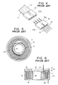
- Fig. 1 is a longitudinal sectional view of a prior art connector device;
- Fig. 2 is a cross-sectional view of the connector device shown in Fig. 1;
- Fig. 3 is a perspective view of another prior art connector device, illustrating the way the coil-end portions of a transmission line are connected to lead wires by means of couplers;
- Fig. 4 is a partial, enlarged perspective view illustrating the way one of the coil-end portions of the transmission line of Fig. 3 is connected to the lead wires;
- Fig. 5 is a cross-sectional view showing a modification of the prior art connector device of Figs. 1 and 2, in which a housing assembly is filled with grease, thereby preventing vibration of the transmission line;
- Fig. 6 is a longitudinal sectional view of the connector device shown in Fig. 5;
- Fig. 7 is a cross-sectional view of the prior art connector device for illustrating an awkward situation of the transmission line loosened substantially to its extremity;
- Fig. 8 is a longitudinal sectional view of a connector device according to an embodiment of the present invention;
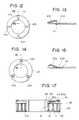
- Fig. 9 is a top view showing in detail a
vibration restraining plate 40 shown in Fig. 8; - Fig. 10 is a cross-sectional view of the connector device shown in Fig. 8;
- Fig. 11 is a perspective view of a
transmission line 11 for illustrating the way aresilient tongue 45 shown in Fig. 10 is held in position; - Fig. 12 is a top view showing in detail a modification of the vibration restraining plate;
- Fig. 13 is a partial sectional view taken along line XIII-XIII of Fig. 12;
- Fig. 14 is a top view showing in detail another modification of the vibration restraining plate;
- Fig. 15 is a partial sectional view taken along line XV-XV of Fig. 14;
- Fig. 16 is an exploded perspective view of a connector device according to another embodiment of the invention;
- Fig. 17 is a longitudinal sectional view of the connector device shown in Fig. 16;
- Fig. 18 is a partial perspective view showing in detail the junction between a transmission line and lead wires of the connector device of Fig. 16;
- Fig. 19 is a partial sectional view taken along line A-A' of Fig. 18;
- Fig. 20 is a perspective view of the connector device of Fig. 16 in an assembled state;
- Fig. 21 is a top view of a connector device according to still another embodiment of the invention;
- Fig. 22 is a longitudinal sectional view of the connector device shown in Fig. 21;
- Fig. 23 is a top view of a guide member or a
scaler 93 shown in Fig. 21 and 22; - Fig. 24 is a side view of the
scaler 93; - Fig. 25 is a bottom view of the
scaler 93; and - Fig. 26 is an exploded perspective view of an optical transmission line threaded with optical fibers.
- Figs. 1 to 7 show conventional connector devices applied to a vehicular steering system. The devices each comprise a belt-shaped transmission line or
flat cable 11, coiled in the shape of a convolution, specifically a spiral, and ahousing assembly 12 containing thecable 11. Thehousing assembly 12 includes amovable housing 13 on the inner-cylinder side and astationary housing 14 on the outer-cylinder side. - The inner-cylinder-
side housing 13 is formed integrally of aninner cylinder 15 and aflange 16. An inner coil-end portion 11a of the coiledflat cable 11 is fixed to theinner cylinder 15 by means of a fixingring 17, as shown in Fig. 2. Theflange 16 faces and covers the upper edge of thecable 11. - The outer-cylinder-
side housing 14 is composed of an inner-cylinder shaft 20, aflange 19, and anouter cylinder 18. Theinner cylinder 15 of the inner-cylinder-side housing 13 is rotatably fitted on the outer peripheral wall of theshaft 20. Theflange 19 extends integrally outward from the lower end of theshaft 20, in the radial direction thereof, and faces and covers the lower edge of the coiledflat cable 11. Theouter cylinder 18 is formed on the outer peripheral edge of theflange 19, so as to extend parallel to and coaxial with theshaft 20. An outer coil-end portion 11b of thecable 11 is fixed to theouter cylinder 18. - The
inner housing 13 is fixed to the side of a steering wheel (not shown) and a steering shaft (not shown), while theouter housing 14 is fixed to the side of a steering column (not shown). The two housings can rotate relatively, within a range such that the coiledflat cable 11 can be tightened or loosened. - Lead
wires 21 are connected to the inner coil-end portion 11a of theflat cable 11. Thewires 21 are drawn out of theinner housing 13 through an aperture which is bored through theflange 16 of thehousing 13. Likewise,lead wires 22 are connected to the outer coil-end portion 11b of thecable 11. Thewires 22 are drawn out of theouter housing 14 through an aperture which is bored through theflange 19 of thehousing 14. - In an alternative conventional arrangement, the inner and outer coil-end portions of a belt-shaped or flat cable are bent substantially at right angles, and the bent ends are drawn out directly. In Figs. 3 and 4, showing such an arrangement, the inner coil-
end portion 11a of theflat cable 11, drawn out of the inner-cylinder-side housing 13, is fixed thereto with the use of fixing means 25. Likewise, the outer coil-end portion 11b, drawn out of the outer-cylinder-side housing 14, is fixed thereto by using fixing means 29. Cable-side couplers end portions individual conductors 11c of theflat cable 11, on its inner-end side, are connected to their correspondingfemale contacts 27a of thecoupler 27, by pressure-coupling. A wire-side coupler 32 is connected to thefemale coupler 27.Conductors 21a of each of thelead wires 21 are connected to one ofmale contacts 32a of thecoupler 32 by pressure-coupling. In Fig. 4, only thecontacts couplers female coupler 28 is connected to a wire-side coupler 34, to which thelead wires 22 are connected. - The
lead wires 21 are connected, for example, to an air bag system (not shown), a combination switch (not shown),etc., which are attached to the side of the steering wheel and the steering shaft. Thelead wires 22 are connected to apparatuses on the steering-column side or on the vehicle-body side. - In the prior art connector device constructed in this manner, the
flat cable 11 always electrically connects the apparatuses on the movable-member side, i.e., on the side of the steering wheel and the steering shaft, and the apparatuses on the fixed-member side, i.e., on the side of the steering column, without using any sliding-contact portion, such as a combination of a slip ring and a brush. Within the rotatable range of the steering wheel, such an electrical connection is ensured without regard to the rotation of the wheel. Thus, the connector device of this type constitutes a transmission line which is more reliable than the one provided by the connector device of the slip-ring type. - In order to permit tightening and loosening, however, the
flat cable 11 is contained loosely in a chamber A which is defined by the inner- and outer-cylinder-side housings cable 11 vibrates and produces noise. To prevent such production of noise, an arrangement has been tried such that the space A is filled withgrease 23, as shown in Figs. 5 and 6. This arrangement has a substantial effect on the prevention of the production of noise. However, thegrease 23 is so viscous that theflat cable 11 cannot move smoothly. Therefore, the necessary torque for the rotation of the steering wheel is increased, and also, the tensile stress acting on thecable 11 becomes greater. Thus, thecable 11 is liable to snap. - If the inner-cylinder-
side housing 13 is rotated near to the extremity in the loosening direction of theflat cable 11, that part of thecable 11 near its inner coil-end portion is liable to bend sigmoidally, as shown in Fig. 7. If such bending is repeated, thecable 11 can be easily broken, at the bent portion, by fatigue. - In the prior art arrangement of electrical connection shown in Fig. 4, moreover, there are three junctions; between the
conductors 11c of theflat cable 11 and thefemale contacts 27a of the cable-side coupler 27, between theconductors 21a of thelead wires 21 and themale contacts 32a of the wire-side coupler 32, and between the female andmale contacts - Referring now to Figs. 8 to 26, connector devices according to the present invention will be described in detail.
- Figs. 8 to 10 show an embodiment of the present invention. In these drawings, like reference numerals refer to like components having substantially the same constructions and functions as in the prior art connector device shown in Figs. 1 to 4. Detailed description of these components is omitted herein.
- In the connector device according to this embodiment, a
vibration restraining plate 40 is disposed in a space B, which is defined between aflange 16 of an inner-cylinder-side housing 13 and anupper side edge 11d of aflat cable 11 coiled in a convolution or spiral. As shown in Figs. 8 and 9, thevibration restraining plate 40 is a ring-shaped resilient metal plate which is made of phosphor bronze. The outside diameter of theplate 40 is shorter than the inside diameter of anouter cylinder 18 of an outer-cylinder-side housing 14. The inside diameter of theplate 40 is longer than the outside diameter of aninner cylinder 15 of the inner-cylinder-side housing 13. Threebent spring pieces 40a are formed, by bending, at regular intervals on anupper surface 40d of theplate 40, so as to protrude radially outward from the inner peripheral edge thereof. As shown in Fig. 8, thespring pieces 40a have their respective top portions 40b abutting against the inner wall surface of theflange 16, to be bent thereby. Thus, alower surface 40c of thevibration restraining plate 40 is pressed softly against theupper side edge 11d of theflat cable 11, by means of the repulsive force of the top portions 40b. As a result, thecable 11, which is contained loosely in the space A insidehousing assembly 12, is restrained from vibrating, and therefore, from producing noise. - The
vibration restraining plate 40 need only be pressed softly against theupper side edge 11d of theflat cable 11. Therefore, the force of theplate 40 to suppress the tightening or loosening action of thecable 11 is so weak that it cannot increase the torque for the rotation of the inner-cylinder-side housing 13 considerably. - In the embodiment described above, the
vibration restraining plate 40 is provided with the threespring pieces 40a. However, the number and mechanical strength of the spring pieces may be determined as required, depending on the necessary pressure to be applied to theflat cable 11. In the above embodiment, moreover, thespring pieces 40a are formed on the inner peripheral edge of the restrainingplate 40. Alternatively or besides, the spring pieces may be formed on the outer peripheral edge of theplate 40. - Figs. 12 and 13 show a modification of the vibration restraining plate. A restraining
plate 41 of this modification includes fourspring pieces 41a, which are formed, by bending, at regular intervals on anupper surface 41d of theplate 41, so as to protrude radially inward from the outer peripheral edge thereof. - Figs. 14 and 15 show another modification of the vibration restraining plate.
Spring pieces 42a of a restrainingplate 42 of this modification are formed by cutting and raising part of a ring-shaped plate. Eachspring piece 42a is raised from a position on anupper surface 42d of theplate 42, at an outward radial distance substantially equal to a quarter of the width of the ring, from the inner peripheral edge thereof. - In any of the aforementioned vibration restraining plates, the spring pieces are formed integrally with the plate, by bending or raising. Alternatively, however, separate spring pieces may be fixed to the restraining plate.
- In the arrangement of Figs. 8 and 9, moreover, the
vibration restraining plate 40 is interposed between theflange 16 of the inner-cylinder-side housing 13 and theupper side edge 11d of theflat cable 11. Alternatively or besides, the restraining plate may be interposed between aflange 19 of the outer-cylinder-side housing 14 and the lower side edge of thecable 11. - Another feature of the present invention lies in that a
resilient tongue 45 is located along the outer surface of the coiledflat cable 11, which extends from theinner cylinder 15, as shown in Fig. 10. Theresilient tongue 45 is formed, for example, of a polyester sheet of a suitable thickness. Aproximal end 45a of thetongue 45 is bonded to the outer surface of the inner coil-end portion 11a of theflat cable 11, i.e., that surface thereof opposite to theinner cylinder 15, as shown in Fig. 11. Then, theproximal end 45a, along with thecable 11, is fixed to thecylinder 15 by means of a fixingring 17, as shown in Fig. 10. Adistal end 45b of theresilient tongue 45 leaves the fixingring 17 at a position where the fixingring 17 terminates after covering substantially the entire periphery of theinner cylinder 15. Thedistal end 45b is pressed against the inner surface of the coiledflat cable 11, by its own resilience. - When the
flat cable 11 is loosened substantially to the limit, by a rocking motion of the inner-cylinder-side housing 13, for example, the outer surface of that portion of thecable 11 near theinner cylinder 15 is in contact with theresilient tongue 45. Thus, thecable 11 is prevented from being deformed further, that is, from bending sigmoidally. - In the arrangement shown in Fig. 10, the
resilient tongue 45 extends from theinner cylinder 15, along the outer surface of theflat cable 11, and theproximal end 45a of thetongue 45 is bonded to thecable 11. Alternatively, however, theresilient tongue 45 may be made to extend along the inner surface of thecable 11, and be bonded to thecable 11 substantially over the full length of thetongue 45. In this case, the inner coil-end portion of thecable 11 is so rigid that it can hardly bend sigmoidally. - In an alternative arrangement the inner cylinder portion may be fixed to the stationary housing and the outer cylinder portion to the movable housing.
- Figs. 16 to 20 show a connector device according to another embodiment of the present invention. In this device, a housing assembly, used in place of the
housing assembly 12 of Fig. 10, is composed of three principal parts. More specifically, the housing assembly according to the second embodiment comprises afirst housing 50, asecond housing 60, and abaseplate 70. In Figs. 16 to 20, like reference numerals refer to like components having substantially the same constructions and functions as those shown in Figs. 8 to 10. Detailed description of these portions is omitted herein. - The
first housing 50 includes aninner cylinder 51 and a ring-shapedflange 52. Theflange 52 is formed integrally on the upper end of the outer peripheral wall of thecylinder 51, so as to extend radially outward therefrom. A lead-wire retaining portion 52c, having aslit groove 52d, is formed at a predetermined position on the inner peripheral edge of theflange 52. Leadwires 21 are fitted in theslit groove 52d. Also, astep portion 52a is formed on the outer peripheral edge of theflange 52. A flange 61 (mentioned later) of thesecond housing 60 is loosely fitted on thestep portion 52a for rotation. Astep portion 51a is formed on the lower end edge of theinner cylinder 51. The inner peripheral edge of thebaseplate 70 is loosely fitted on thestep portion 51a for rotation. - The
baseplate 70, which is ring-shaped, has an outside diameter substantially equal to that of theflange 52 of thefirst housing 50. A lead-wire retaining block 71 is formed integrally on a predetermined portion of the outer peripheral edge of thebaseplate 70. The retainingblock 71 has aslit groove 72 which opens on one side thereof, with respect to the circumferential direction of thebaseplate 70. Leadwires 22 are fitted in theslit groove 72. Three retainingrecesses 70a are formed, at regular circumferential intervals, on the outer peripheral edge of thebaseplate 70. - The
second housing 60 includes anouter cylinder 62 and aflange 61. Theouter cylinder 62 has an inside diameter a little greater than the outside diameter of theflange 52 of thefirst housing 50. Theflange 61 is formed integrally on the top end portion of the inner peripheral wall of theouter cylinder 62, so as to protrude radially inward therefrom. As mentioned before, the inner peripheral edge of theflange 61 is rotatably fitted on thestep portion 52a of theflange 52 of thefirst housing 50. Three retainingclicks 63 are formed, at regular circumferential intervals, on the lower end edge of theouter cylinder 62. With theclicks 63 individually engaging the retaining recesses 70a of thebaseplate 70, thebaseplate 70 and thesecond housing 60 rotate as a body, along thestep portion 51a of theinner cylinder 51 of thefirst housing 50 and the outer periphery of theflange 52, respectively. Acover portion 64 protrudes integrally from the outer wall of theouter cylinder 62, corresponding in position to the lead-wire retaining block 71 of thebaseplate 70. Thus, thecover portion 64 is adapted to enclose the retainingblock 71. - Two
flat conductors 11c are exposed from an inner coil-end portion 11a offlat cable 11.Conductors 21a, exposed at one end of thelead wires 21, are connected directly to theconductors 11a by soldering or pressure-coupling, without using couplers or the like. Thelead wires 21 are bent substantially at right angles, in the region near the junction with thecable 11. The other end portions of thewires 21 extend upward. In Figs. 18 and 19, one of theconductors 11c of theflat cable 11 is shown directly connected to one of theconductors 21a of thelead wires 21 by pressure-coupling such that a pressure-coupling fitting 80, in the form of a plate, is crimped around the joint between them. Thus, by connecting theconductors 11c of thecable 11 and theconductors 21a of thelead wires 21 without the use of couplers, the number of components used in the connector device, and hence the manufacturing cost, can be reduced. Moreover, thelead wires 21 and theflat cable 11 are connected at only one junction, so that the possibility of a wire snapping at the junction or production of noise is very little, thus ensuring improved reliability of the connector device. - The junction between the
flat cable 11 and thelead wires 21 is covered by a pair ofsupporters 82, which are formed of an insulating material, such as polyacetal. Eachsupporter 82 is L-shaped so as to fit the shape of the structure in the vicinity of the junction between thecable 11 and thelead wires 21. Those portions of thewires 21 which are not covered by thesupporters 82 are shielded with a flexibleprotective tube 83. - The two
flat conductors 11c are exposed also from an outer coil-end portion 11b of thecable 11.Conductors 22a, exposed at one end of thelead wires 22, are connected directly to theconductors 11c by pressure-coupling, without using couplers or the like. Thelead wires 22 are bent substantially at right angles, in the region near the junction with thecable 11. The other end portions of thewires 22 extend downward. The junction between thecable 11 and thelead wires 22 is covered by a pair ofsupporters 85, which are similar to thesupporters 82. Those portions of thelead wires 22 which are not covered by thesupporters 85 are shielded with a flexibleprotective tube 86. - The
lead wires 21, covered by theprotective tube 83, are passed through a ring-shapedvibration restraining plate 40, and are fitted into theslit groove 52d of the lead-wire retaining portion 52c of thefirst housing 50, so as to project upward from thehousing 50. Thelead wires 22, covered by theprotective tube 86, are fitted into theslit groove 72 of the lead-wire retaining block 71 of thebaseplate 70, so as to project downward from thebaseplate 70. With thelead wires flat cable 11 is placed on the upper surface of thebaseplate 70, and the restrainingplate 40 is put on the upper end edge of thecable 11. Thereafter, theinner cylinder 51 of thefirst housing 50 is inserted into a cylindrical center space of the coiledcable 11. Then, thestep portion 51a of thecylinder 51 is fitted into the inner peripheral edge of thebaseplate 70 so that the lower surface of theflange 52 abuts againstspring pieces 40a of thevibration restraining plate 40. In this state, thesecond housing 60 is fitted onto thefirst housing 50 and thebase plate 70, from above thefirst housing 50. In doing this, thecover portion 64 is put on the lead-wire retaining block 71, and the retaining clicks 63 are caused to engage the retaining recesses 70a of thebaseplate 70. Thus, the assembling of the connector device is completed. If thefirst housing 50 is used as a movable housing and is fixed to a rotatable member on the side of the steering wheel and the steering shaft, for example, and if the combination of thesecond housing 60 and thebase plate 70 is used as a stationary housing and is fixed to a fixed member on the steering-column side, thefirst housing 50 can be made rotatable relatively to thesecond housing 60 and thebaseplate 70. - Alternatively, the
first housing 50 may be used as the stationary housing which is fixed to the fixed member on the steering-column side, for example. In this case, the combination of thesecond housing 60 and thebaseplate 70 is used as the movable housing which is fixed to the side of the steering wheel and the steering shaft. In such an arrangement, thesecond housing 60 and thebaseplate 70 are rotatable relatively to thefirst housing 50. - Since the
lead wires slit grooves second housings baseplate 70. In comparison with the case of thehousing assembly 12 of the connector device shown in Fig. 8, therefore, the components of the housing assembly according to this embodiment are simple in configuration. Thus, the housing assembly can be formed more easily when it is molded by using an injection-molding machine. In consequence, the manufacturing cost can be reduced. - Figs. 21 to 25 show a connector device according to still another embodiment of the present invention. In this embodiment, indicator means is provided on the upper surface of the
flange 52 of thefirst housing 50 of the connector device shown in Figs. 16 to 20. The indicator means serves to indicate the number of revolutions of thefirst housing 50, for use as the movable housing, relative to thesecond housing 60 as the stationary housing. - More specifically, a
spiral groove 90 is formed on the upper surface of theflange 52 of thefirst housing 50, winding around the center of rotation of thehousing 50. Arevolution indicator piece 92 is fitted in thegroove 90. It can slide along thegroove 90, thus rotating relatively to thefirst housing 50. - On the other hand, a
proximal portion 93d of an L-shaped scaler or guidemember 93, used to indicate the number of revolutions of thefirst housing 50, is fixed to the upper portion of anouter wall 62a of thesecond housing 60, as the stationary housing. A bent-end arm 93a of thescaler 93 lies over the upper surface of theflange 52 of thefirst housing 50, extending across and at right angles to thespiral groove 90. Thescaler 93 is formed of a transparent plastic material in order that theindicator piece 92 can be seen through it. Aguide groove 93c is formed on alower surface 93b of thearm 93a which faces thegroove 90. Thegroove 93c extends at right angles to thegroove 90. Theindicator piece 92, which is fitted in thespiral groove 90, is fitted also in theguide groove 93c. Thus, thegroove 93c restricts the movement of theindicator piece 92 so that thepiece 92 is prevented from moving in the circumferential direction of thefirst housing 50, with respect to thescaler 93, and can move only in the radial direction of thehousing 50.Divisions 0, 1, 2, 3, 4 and 5 are engraved on the upper surface of thearm 93a of thescaler 93. These divisions are used to indicate the allowable number of revolutions of thefirst housing 50. - As the
first housing 50 rotates, therevolution indicator piece 92 is caused to move radially over a distance corresponding to the number of revolutions of thehousing 50, by a joint action of thespiral groove 90 of thehousing 50 and theguide groove 93c of thescaler 93. The number of revolutions of thefirst housing 50, relative to thesecond housing 60, can be indicated by the position of the movedpiece 92. Thus, in the connector device fitted with the revolution indicator means, the winding state of the flat cable in the housing assembly can be detected easily. When mounting this connector device on a steering system, for example, thefirst housing 50 is rotated to the middle position of its rotatable range such that theindicator piece 92 is adjusted to the point halfway between the divisions 2 and 3. In this state, thefirst housing 50 is mounted on the side of the steering wheel and the steering shaft, which are fixed to their respective positions for a straight advance of the vehicle. On the other hand, thesecond housing 60 and thebaseplate 70 are mounted on the steering-column side. Thus, theflat cable 11 in the housing assembly can be mounted accurately in a normal winding state, so that it is less likely to snap due to wrong mounting of the connector device. - The
guide groove 93c of thescaler 93 may be formed with a slit which opens on the surface of thearm 93a. The slit has a width such that therevolution indicator piece 92 cannot slip therethrough. In this case, thescaler 90 need not be formed of a transparent plastic material through which thepiece 92 can been seen. - If the transmission line is used to transmit electrical signals or electric power, then it is an electric wire cable, such as the
flat cable 11, as in the embodiments described above. When using the transmission line for transmitting optical signals, however, an optical transmission line threaded withoptical fibers 96, as shown in Fig. 26, can be used suitably for that purpose. - According to the embodiments described herein, the connector device of the present invention is applied to a vehicular steering system which is furnished with an air bag system, combination switch, etc. The connector device of this type may, however, be applied to any other suitable arrangements which are expected to transfer electrical or optical signals or electric power between two relatively rotating members which can make only a limited number of revolutions.
Claims (11)
- A connector device having a belt-shaped transmission line (11) coiled in the shape of a convolution, and housing means (12) containing said transmission line, said housing means including a stationary housing (14) attachable to a fixed member and a movable housing (13) attachable to a movable member, said stationary housing (14) being fixedly fitted with one end (11b) of said transmission line and having a first flange portion (19) facing one edge of said coiled transmission line (11), and said movable housing (13) being fixedly fitted with the other end (11a) of said transmission line and having a second flange portion (16) facing the other edge (11d) of said coiled transmission line, so that said movable housing can make a plurality of revolutions relative to said stationary housing, and characterised in that
said connector device comprises vibration restraining means (40) disposed in at least one of spaces which are defined between said one edge of said transmission line (11) and said first flange portion (19), and between said other edge (11d) of said transmission line and said second flange portion (16), whereby said transmission line (11) is pressed in a direction transverse to said edges so as to be restrained from vibrating. - A connector device according to claim 1, wherein said vibration restraining means is a ring-shaped plate (40), having a resilient member (40a) formed on that surface thereof which faces the adjacent flange portion.
- A connector device according to claim 2, wherein said resilient member (40a) is formed by bending at least one of the inner and outer peripheral edges of said ring-shaped plate (40).
- A connector device according to claim 1, 2 or 3 wherein said stationary housing (13) includes an inner cylinder portion (15) fixedly fitted with said one end of said transmission line (11a), as an inner coil end, and a resilient tongue (45) extending along said transmission line, the proximal end (45a) of said tongue being fixed to said inner cylinder portion.
- A connector device according to claim 1, 2, 3 or 4 wherein said movable housing includes an independent outer cylinder portion (60) fitted loosely on the outer peripheral edge (52a) of said first flange portion (52) of said stationary housing, said second flange portion (70) and said outer cylinder portion (60) of said movable housing being engagedly fixed to each other by engaging means.
- A connector device according to claim 1, 2 or 3 wherein said movable housing includes an inner cylinder portion fixedly fitted with said other end of said transmission line (11a), as an inner coil end, and a resilient tongue (45) extending along the transmission line (11), the proximal end (45a) of said tongue being fixed to said inner cylinder portion.
- A connector device according to claim 1, 2, 3 or 6 wherein said stationary housing includes an independent outer cylinder portion (60) fitted loosely on the outer peripheral edge (52a) of said second flange portion (52) of said movable housing (50), said first flange portion (70) and said outer cylinder portion (60) of said stationary housing being engagedly fixed to each other by engaging means.
- A connector device according to any preceding claim wherein said second flange portion is formed, on the outer surface thereof, with a spiral groove (90) whose number of turns is equivalent to the allowable number of revolutions of said movable housing, a sliding member (92) fitted in said spiral groove, and a guide member (93) having one end fixed to said stationary housing and the other end extending across said spiral groove, said sliding member (92) being adapted to slide relatively on said spiral groove (90) as said movable housing rotates, so that the number of revolutions of said movable housing is indicated by the position of said moved sliding member, said guide member restraining said sliding member from moving in the circumferential direction, and allowing said sliding member to move only in the radial direction.
- A connector device according to any preceding claim wherein said transmission line is an electric wire cable.
- A connector device according to claim 9, wherein said electric wire cable includes conductors connected directly to conductors of lead wires by pressure-coupling, using a pressure-coupling fitting.
- A connector device according to any preceding claim wherein said transmission line is an optical transmission line threaded with optical fibres.
Applications Claiming Priority (4)
| Application Number | Priority Date | Filing Date | Title |
|---|---|---|---|
| JP55466/86 | 1986-04-15 | ||
| JP5546686U JPS62167387U (en) | 1986-04-15 | 1986-04-15 | |
| JP56102/86 | 1986-04-16 | ||
| JP1986056102U JPH0332076Y2 (en) | 1986-04-16 | 1986-04-16 |
Publications (3)
| Publication Number | Publication Date |
|---|---|
| EP0243047A2 EP0243047A2 (en) | 1987-10-28 |
| EP0243047A3 EP0243047A3 (en) | 1989-12-13 |
| EP0243047B1 true EP0243047B1 (en) | 1993-10-06 |
Family
ID=26396356
Family Applications (1)
| Application Number | Title | Priority Date | Filing Date |
|---|---|---|---|
| EP87303123A Expired - Lifetime EP0243047B1 (en) | 1986-04-15 | 1987-04-09 | Connector device for a transmission line connecting two relatively rotating members |
Country Status (4)
| Country | Link |
|---|---|
| US (1) | US4744763A (en) |
| EP (1) | EP0243047B1 (en) |
| CA (1) | CA1276995C (en) |
| DE (1) | DE3787665T2 (en) |
Families Citing this family (74)
| Publication number | Priority date | Publication date | Assignee | Title |
|---|---|---|---|---|
| EP0241311B1 (en) * | 1986-04-11 | 1993-03-17 | Canon Kabushiki Kaisha | Process for forming deposited film |
| JPH0636040Y2 (en) * | 1988-03-31 | 1994-09-21 | アルプス電気株式会社 | Cable reel |
| JPH0454713Y2 (en) * | 1988-04-04 | 1992-12-22 | ||
| US4925122A (en) * | 1988-04-20 | 1990-05-15 | Alps Electric Co., Ltd. | Cable reel |
| JPH01161589U (en) * | 1988-04-30 | 1989-11-09 | ||
| JPH0454714Y2 (en) * | 1988-05-23 | 1992-12-22 | ||
| US5273985A (en) * | 1988-07-04 | 1993-12-28 | Eisai Co., Ltd. | Glycerin derivative and its pharmacological use |
| SE465263B (en) * | 1988-07-18 | 1991-08-19 | Gen Engineering Bv | DEVICE FOR ELECTRICAL CONNECTION OF EQUIPMENT ORGANIZED IN OR IN THE STEERING OF A MOTOR VEHICLE |
| JPH0714304Y2 (en) * | 1988-12-21 | 1995-04-05 | アルプス電気株式会社 | Cable reel |
| JPH0720868Y2 (en) * | 1988-12-22 | 1995-05-15 | アルプス電気株式会社 | Cable reel |
| JPH02215071A (en) * | 1989-02-14 | 1990-08-28 | Furukawa Electric Co Ltd:The | Connector device |
| JP2507808B2 (en) * | 1989-05-31 | 1996-06-19 | 古河電気工業株式会社 | Connector device |
| DE58907793D1 (en) * | 1989-09-12 | 1994-07-07 | Petri Ag | Power line connector for bridging wire breaks between mutually rotatable parts. |
| EP0437642B1 (en) * | 1990-01-13 | 1994-11-09 | Petri AG | Connector element for the settlement of an electrical connection between two parts that can be rotated relatively to each other |
| DE4031235A1 (en) * | 1990-03-02 | 1991-09-12 | Thomas & Betts Corp | CONNECTING DEVICE |
| US5049082A (en) * | 1990-03-15 | 1991-09-17 | Imo Industries, Inc. | Thru wire helm assembly |
| DE4027952C3 (en) * | 1990-09-04 | 1998-02-12 | Eaton Controls Gmbh | Electrical connection device |
| US5061195A (en) * | 1990-09-24 | 1991-10-29 | Methode Electronics, Inc. | Clock spring housing and assembly |
| DE4129450A1 (en) * | 1990-10-04 | 1992-04-09 | Methode Electronics Inc | CLOCK SPRING INTERMEDIATE CONNECTOR |
| JPH0711424Y2 (en) * | 1990-10-05 | 1995-03-15 | 古河電気工業株式会社 | Rotating connector |
| JPH0711426Y2 (en) * | 1990-10-24 | 1995-03-15 | 古河電気工業株式会社 | Rotating connector end support mounting structure |
| JPH0711427Y2 (en) * | 1990-10-24 | 1995-03-15 | 古河電気工業株式会社 | Rotating connector |
| US5230713A (en) * | 1990-11-17 | 1993-07-27 | Kabelmetal Electro Gesellschaft Mit Beschrankter Haftung | Device for the transmission of current between two end points |
| US5078466A (en) * | 1991-04-19 | 1992-01-07 | Allied-Signal Inc. | Fiber optic rotary joint |
| JP3050636B2 (en) * | 1991-06-04 | 2000-06-12 | 古河電気工業株式会社 | Connector device |
| DE9107726U1 (en) * | 1991-06-22 | 1991-08-08 | Kabelmetal Electro Gmbh, 3000 Hannover, De | |
| JP2575481Y2 (en) * | 1991-08-21 | 1998-06-25 | 古河電気工業株式会社 | Fixing structure of flat cable connection part in rotary connector |
| JPH0540620U (en) * | 1991-10-30 | 1993-06-01 | 日本精工株式会社 | Roller type linear motion guide device |
| US5337694A (en) * | 1992-02-25 | 1994-08-16 | Nix Charles D | Trim apparatus for outboard motor |
| JP2579055Y2 (en) * | 1992-03-19 | 1998-08-20 | 住友電気工業株式会社 | Cable reel |
| DE4233914A1 (en) * | 1992-10-08 | 1994-04-14 | Kabelmetal Electro Gmbh | Device for signal transmission between two end points |
| DE4235055C2 (en) * | 1992-10-17 | 1996-04-04 | Daimler Benz Ag | Housing for holding a contact spiral |
| DE4314648A1 (en) * | 1993-05-04 | 1994-11-10 | Kabelmetal Electro Gmbh | Method for producing a device for signal transmission between two end points |
| JPH076841A (en) * | 1993-06-18 | 1995-01-10 | Sumitomo Electric Ind Ltd | Electric signal transmitting device |
| DE4329117C2 (en) * | 1993-08-30 | 2002-02-07 | Takata Petri Ag | Power connector for a multi-pole cable routed in a housing #### |
| DE4329119A1 (en) * | 1993-08-30 | 1995-03-02 | Petri Ag | Power line connector for bridging wire breaks between mutually rotatable parts |
| DE4333807A1 (en) * | 1993-10-04 | 1995-04-06 | Gore W L & Ass Gmbh | Spiral cable socket |
| DE19511693A1 (en) * | 1994-05-26 | 1995-11-30 | Teves Gmbh Alfred | Motor vehicle steering column switch with angular spring |
| US6095836A (en) * | 1994-07-19 | 2000-08-01 | Methode Electronics, Inc. | Clockspring connector with carrier member |
| US6213797B1 (en) | 1994-07-19 | 2001-04-10 | Methode Electronics, Inc. | Clockspring having non-compliant and compliant roller members |
| US6012935A (en) * | 1994-07-19 | 2000-01-11 | Methode Electronics, Inc. | Clockspring connector with carrier member |
| DE4436172C2 (en) * | 1994-10-10 | 2001-02-01 | Eaton Controls Gmbh | Electrical connection device |
| DE4441387A1 (en) * | 1994-11-21 | 1996-06-05 | Gore W L & Ass Gmbh | Coiled-cable holder esp. for occupant restraint air-bag in motor vehicle |
| DE4441386A1 (en) * | 1994-11-21 | 1996-06-05 | Gore W L & Ass Gmbh | Coiled-cable reel holder e.g. for occupant safety airbag in motor vehicle |
| JPH08162241A (en) * | 1994-12-09 | 1996-06-21 | Yazaki Corp | Electrically connecting device for fixed body and rotating body |
| US5580259A (en) * | 1995-02-10 | 1996-12-03 | Methode Electronics, Inc. | Clockspring with resilient flat cable carrier apparatus |
| JP3373966B2 (en) * | 1995-02-10 | 2003-02-04 | アルプス電気株式会社 | Rotating connector |
| JP3199595B2 (en) * | 1995-02-22 | 2001-08-20 | アルプス電気株式会社 | Rotating connector |
| FR2731300B1 (en) * | 1995-03-03 | 1997-05-30 | Magneti Marelli France | IMPROVED ROTATING ELECTRIC CONTACTOR WITH REDUCED OPERATING NOISE |
| FR2734090B1 (en) * | 1995-05-09 | 1997-08-01 | Magneti Marelli France | IMPROVED ROTATING ELECTRIC CONTACTOR WITH REDUCED OPERATING NOISE |
| JPH0973965A (en) * | 1995-09-04 | 1997-03-18 | Sumitomo Electric Ind Ltd | Cable reel |
| US6841735B1 (en) * | 1996-04-03 | 2005-01-11 | Methode Electronics, Inc. | Flat cable and modular rotary anvil to make same |
| DE19701510A1 (en) * | 1997-01-17 | 1998-07-23 | Stemmann Technik Gmbh | Signal conductor |
| JPH11191346A (en) * | 1997-12-26 | 1999-07-13 | Niles Parts Co Ltd | Column switch with turning connector |
| US6131946A (en) * | 1998-06-30 | 2000-10-17 | Toyoda Gosei Co., Ltd. | Steering wheel |
| JP3518995B2 (en) * | 1998-07-02 | 2004-04-12 | アルプス電気株式会社 | Rotating connector |
| JP4004692B2 (en) | 1999-09-24 | 2007-11-07 | 松下電器産業株式会社 | Rotating connector |
| EP1093201B1 (en) * | 1999-10-13 | 2009-12-09 | THOMSON multimedia | Cable reel and electromagnetic wave communication device equipped with such a reel |
| US6425774B1 (en) * | 1999-11-11 | 2002-07-30 | Autonetworks Technologies, Ltd. | Rotary connection device |
| DE19960205A1 (en) * | 1999-12-14 | 2001-06-28 | Alcatel Sa | Device for signal transmission between two end points |
| US6819854B1 (en) | 2003-06-02 | 2004-11-16 | Moog Components Group Inc. | Fiber optic rotary flex |
| ES2271745T3 (en) * | 2003-07-22 | 2007-04-16 | Trw Automotive Safety Systems Gmbh | MANAGEMENT DEVICE WITH THE STATIONARY CENTRAL PART. |
| DE20311255U1 (en) * | 2003-07-22 | 2003-12-04 | Trw Automotive Safety Systems Gmbh | Vehicle steering device with a fixed middle part |
| US7290789B2 (en) | 2003-07-22 | 2007-11-06 | Trw Automotive Safety Systems Gmbh | Vehicle steering device with stationary central part |
| US20050048821A1 (en) * | 2003-08-25 | 2005-03-03 | Bolen Patrick A. | Clockspring flat cable termination |
| US7192293B2 (en) * | 2004-10-15 | 2007-03-20 | Delphi Technologies, Inc. | Non-reversing short tape coil device |
| JP4891701B2 (en) * | 2006-08-23 | 2012-03-07 | ナイルス株式会社 | Rotating connector device |
| WO2010026123A1 (en) * | 2008-09-02 | 2010-03-11 | Kulicke And Soffa Die Bonding Gmbh | Apparatus for manipulating objects, in particular semiconductor chips, and a flexible flat cable |
| US8325229B2 (en) * | 2008-11-26 | 2012-12-04 | Robert Bosch Gmbh | Camera having a slip ring and pan-tilt mechanism |
| US8118147B2 (en) * | 2009-09-11 | 2012-02-21 | Better Place GmbH | Cable dispensing system |
| US8376103B1 (en) * | 2010-02-11 | 2013-02-19 | Sonosite, Inc. | Cable management system |
| DE102010022542A1 (en) * | 2010-06-02 | 2011-12-08 | Leopold Kostal Gmbh & Co. Kg | Coil spring cartridge for use in motor car, has winding direction-reversing loop arranged between two sections, and guide arranged on strip cable, where guide is formed as annular carrier that is mounted on stator to slide |
| CN106252031B (en) | 2015-06-12 | 2020-08-04 | 松下知识产权经营株式会社 | Magnetic device and power conversion apparatus using the same |
| DE202019105125U1 (en) * | 2019-09-16 | 2020-10-21 | Igus Gmbh | Rotary guide for one or more lines |
Family Cites Families (5)
| Publication number | Priority date | Publication date | Assignee | Title |
|---|---|---|---|---|
| US3657491A (en) * | 1970-05-28 | 1972-04-18 | Illinois Tool Works | Cord reel |
| US3763455A (en) * | 1971-12-17 | 1973-10-02 | Gen Motors Corp | Electrically coupled steering column |
| US4422699A (en) * | 1980-10-07 | 1983-12-27 | Honda Giken Kogyo Kabushikikaisha | Electrical connector device in a vehicular steering system |
| JPS57134350A (en) * | 1981-02-13 | 1982-08-19 | Honda Motor Co Ltd | Connector for steering of vehicle |
| US4540223A (en) * | 1984-03-19 | 1985-09-10 | General Motors Corporation | Positive electrical connecting mechanism |
-
1987
- 1987-04-07 US US07/035,499 patent/US4744763A/en not_active Expired - Lifetime
- 1987-04-09 EP EP87303123A patent/EP0243047B1/en not_active Expired - Lifetime
- 1987-04-09 DE DE3787665T patent/DE3787665T2/en not_active Expired - Lifetime
- 1987-04-14 CA CA000534618A patent/CA1276995C/en not_active Expired - Lifetime
Also Published As
| Publication number | Publication date |
|---|---|
| DE3787665T2 (en) | 1994-05-11 |
| EP0243047A2 (en) | 1987-10-28 |
| US4744763A (en) | 1988-05-17 |
| CA1276995C (en) | 1990-11-27 |
| EP0243047A3 (en) | 1989-12-13 |
| DE3787665D1 (en) | 1993-11-11 |
Similar Documents
| Publication | Publication Date | Title |
|---|---|---|
| EP0243047B1 (en) | Connector device for a transmission line connecting two relatively rotating members | |
| EP0401028B1 (en) | Connector devices | |
| EP0556779B2 (en) | Transmission device used between two relatively rotatable components | |
| EP0186935A1 (en) | Spiral flex-circuit system for steering wheels | |
| US5242309A (en) | Rotary connector | |
| US4813878A (en) | Device for transferring current between two contact points which are movable relative to each other | |
| US5059134A (en) | Apparatus for providing an electrical conduction path between two contact locations which are rotatable with respect to each other | |
| JP2738573B2 (en) | Apparatus for transmitting between two end positions relatively movable with respect to each other | |
| EP0482937B1 (en) | Rotary connector | |
| GB2282014A (en) | Cable connector | |
| JPH04298982A (en) | Apparatus for transmitting power between two terminal positions | |
| US5580259A (en) | Clockspring with resilient flat cable carrier apparatus | |
| US4657326A (en) | Current conduction connector for the electrical connection of gas bag collision protection installation | |
| JPH05316630A (en) | Device used to relay electric current between two termination positions | |
| US6783378B2 (en) | Device for transmitting current between two terminals | |
| KR0152593B1 (en) | Rotary connector | |
| CA2187547A1 (en) | Signal transmitting device | |
| US5032084A (en) | Apparatus for providing an electrical conduction path between two contact locations which are rotatable with respect to each other | |
| EP0503380B1 (en) | Electrical connector system | |
| JPH07169544A (en) | Cable reel | |
| JP3709998B2 (en) | Rotating connector | |
| JPH0644052Y2 (en) | Brushless electrical signal transmitter | |
| JPH054707Y2 (en) | ||
| JPH0220791Y2 (en) | ||
| JP3231232B2 (en) | Rotating connector |
Legal Events
| Date | Code | Title | Description |
|---|---|---|---|
| PUAI | Public reference made under article 153(3) epc to a published international application that has entered the european phase |
Free format text: ORIGINAL CODE: 0009012 |
|
| AK | Designated contracting states |
Kind code of ref document: A2 Designated state(s): DE FR GB |
|
| PUAL | Search report despatched |
Free format text: ORIGINAL CODE: 0009013 |
|
| AK | Designated contracting states |
Kind code of ref document: A3 Designated state(s): DE FR GB |
|
| 17P | Request for examination filed |
Effective date: 19900606 |
|
| 17Q | First examination report despatched |
Effective date: 19920220 |
|
| GRAA | (expected) grant |
Free format text: ORIGINAL CODE: 0009210 |
|
| AK | Designated contracting states |
Kind code of ref document: B1 Designated state(s): DE FR GB |
|
| REF | Corresponds to: |
Ref document number: 3787665 Country of ref document: DE Date of ref document: 19931111 |
|
| ET | Fr: translation filed | ||
| PLBE | No opposition filed within time limit |
Free format text: ORIGINAL CODE: 0009261 |
|
| STAA | Information on the status of an ep patent application or granted ep patent |
Free format text: STATUS: NO OPPOSITION FILED WITHIN TIME LIMIT |
|
| 26N | No opposition filed | ||
| REG | Reference to a national code |
Ref country code: GB Ref legal event code: IF02 |
|
| PGFP | Annual fee paid to national office [announced via postgrant information from national office to epo] |
Ref country code: GB Payment date: 20060405 Year of fee payment: 20 |
|
| PGFP | Annual fee paid to national office [announced via postgrant information from national office to epo] |
Ref country code: DE Payment date: 20060406 Year of fee payment: 20 |
|
| PGFP | Annual fee paid to national office [announced via postgrant information from national office to epo] |
Ref country code: FR Payment date: 20060410 Year of fee payment: 20 |
|
| REG | Reference to a national code |
Ref country code: GB Ref legal event code: PE20 |
|
| PG25 | Lapsed in a contracting state [announced via postgrant information from national office to epo] |
Ref country code: GB Free format text: LAPSE BECAUSE OF EXPIRATION OF PROTECTION Effective date: 20070408 |