EP0244538B1 - Combination convection and steamer oven - Google Patents
Combination convection and steamer oven Download PDFInfo
- Publication number
- EP0244538B1 EP0244538B1 EP86308669A EP86308669A EP0244538B1 EP 0244538 B1 EP0244538 B1 EP 0244538B1 EP 86308669 A EP86308669 A EP 86308669A EP 86308669 A EP86308669 A EP 86308669A EP 0244538 B1 EP0244538 B1 EP 0244538B1
- Authority
- EP
- European Patent Office
- Prior art keywords
- oven
- water
- steam
- cavity
- fan
- Prior art date
- Legal status (The legal status is an assumption and is not a legal conclusion. Google has not performed a legal analysis and makes no representation as to the accuracy of the status listed.)
- Expired - Lifetime
Links
Images

Classifications
-
- A—HUMAN NECESSITIES
- A47—FURNITURE; DOMESTIC ARTICLES OR APPLIANCES; COFFEE MILLS; SPICE MILLS; SUCTION CLEANERS IN GENERAL
- A47J—KITCHEN EQUIPMENT; COFFEE MILLS; SPICE MILLS; APPARATUS FOR MAKING BEVERAGES
- A47J27/00—Cooking-vessels
-
- F—MECHANICAL ENGINEERING; LIGHTING; HEATING; WEAPONS; BLASTING
- F24—HEATING; RANGES; VENTILATING
- F24C—DOMESTIC STOVES OR RANGES ; DETAILS OF DOMESTIC STOVES OR RANGES, OF GENERAL APPLICATION
- F24C15/00—Details
- F24C15/32—Arrangements of ducts for hot gases, e.g. in or around baking ovens
- F24C15/322—Arrangements of ducts for hot gases, e.g. in or around baking ovens with forced circulation
- F24C15/327—Arrangements of ducts for hot gases, e.g. in or around baking ovens with forced circulation with air moisturising
-
- A—HUMAN NECESSITIES
- A21—BAKING; EDIBLE DOUGHS
- A21B—BAKERS' OVENS; MACHINES OR EQUIPMENT FOR BAKING
- A21B1/00—Bakers' ovens
- A21B1/02—Bakers' ovens characterised by the heating arrangements
- A21B1/24—Ovens heated by media flowing therethrough
-
- A—HUMAN NECESSITIES
- A21—BAKING; EDIBLE DOUGHS
- A21B—BAKERS' OVENS; MACHINES OR EQUIPMENT FOR BAKING
- A21B3/00—Parts or accessories of ovens
- A21B3/04—Air-treatment devices for ovens, e.g. regulating humidity
-
- Y—GENERAL TAGGING OF NEW TECHNOLOGICAL DEVELOPMENTS; GENERAL TAGGING OF CROSS-SECTIONAL TECHNOLOGIES SPANNING OVER SEVERAL SECTIONS OF THE IPC; TECHNICAL SUBJECTS COVERED BY FORMER USPC CROSS-REFERENCE ART COLLECTIONS [XRACs] AND DIGESTS
- Y02—TECHNOLOGIES OR APPLICATIONS FOR MITIGATION OR ADAPTATION AGAINST CLIMATE CHANGE
- Y02P—CLIMATE CHANGE MITIGATION TECHNOLOGIES IN THE PRODUCTION OR PROCESSING OF GOODS
- Y02P60/00—Technologies relating to agriculture, livestock or agroalimentary industries
- Y02P60/80—Food processing, e.g. use of renewable energies or variable speed drives in handling, conveying or stacking
Definitions
- This invention relates to an oven and more particularly to a cooking oven and method for cooking foodstuffs by means of either steam, dry convection hot air or moist convection hot air.
- this invention relates to a food cooking oven which may be operated in three distinct cooking modes and wherein the oven is operated at atmospheric pressure. Cooking may be accomplished in an atmosphere of steam which has been generated within the oven cavity, by means of convection hot air to which water vapor has been added, or by means of dry convection hot air.
- Prior art food preparation ovens have been provided which cook or bake food by means of convection air and wherein moisture is added to the oven cavity to prevent the food from drying out and to provide high quality prepared food.
- Such ovens do not have the ability to cook food by means of steam and therefore do not have the advantages of ovens wherein food is cooked by means of steam.
- Steam is a very effective heat transfer medium since the latent heat of vaporization needed to turn water into steam requires a great deal of thermal energy. When the steam condenses on a food product, this thermal energy will be given up directly to the food product. Steam is, therefore, a much more effective heat transfer medium than is hot air. By cooking food products in an oven in an atmosphere of steam, a great deal of energy will, therefore, be rapidly transferred to the food products.
- An additional benefit of cooking food products with steam is that it prevents drying out of the food products as would occur if the food product were cooked with dry, hot convection air. It is therefore desirable, in order to provide a cooking oven wherein food can be prepared quickly and efficiently, to circulate steam continuously within the oven cavity to cook the food products located therein. Furthermore, since the steam in the oven cavity will continuously condense on the food products as well as on the oven walls, it is desired to continuously generate more steam and to supply this steam continuously to the oven cavity.
- CH-A-630240 discloses a steam and convection cooking oven in which a circulatary fan has a radial rotor onto which water is dripped from a supply vessel through a nozzle. The water enters the rotor in the form of drops or as a jet, is atomised and is then immediately vapourised to provide a flow of steam to the oven cavity.
- This invention provides a steam and convection cooking oven for cooking foodstuffs, the oven comprising; an oven cavity at atmospheric pressure, a heater disposed in said cavity for heating the cavity, a fan for circulating air or steam in said cavity, water supply means for supplying water to said cavity to be atomised by the fan and circulated in the cavity, temperature control means for controlling the temperature in said cavity and mode selection means for causing said cavity to be filled with either steam or convection air, wherein rotatable cup means are provided for receiving water from said water supply means and for forming a sheet of water which is flung onto said fan to be atomised thereby.
- the cooking method comprises the steps of continuously supplying water to the oven, atomizing the supplied water and continuously converting the atomised water to steam by passing it over the heater by action of the fan.
- the oven cavity is maintained at a selected temperature by controlling the heater.
- the steam in the cavity is continuously recirculated over the heater and the oven cavity is maintained at atmospheric pressure.
- a selected quantity of water is cyclically supplied to the oven cavity where it is converted into water vapor by the combined action of the heater and the fan. Furthermore, the oven cavity is maintained at a selected variable temperature by means of the heater. Thus, by selecting the amount of water which is cyclically added to the oven cavity, the moisture level of the air in the oven cavity can be regulated. Furthermore, the range of selectable temperatures for operation of the oven in the hot air convection mode is greater than in the steaming mode.
- the fan In the dry hot air convection mode, the fan circulates the air but no moisture is added to the oven cavity. In this mode, the temperature of the oven cavity may also be selected as desired.
- the rotatable cup may include a reverse taper and a relatively sharp circular edge whereby water flows in a thin film over the edge of the cup and is then slung outwardly and atomized by centrifugal force.
- the fan will then cause the atomised water to flow over the heater whereby the atomised water droplets will be flashed into steam by contact with a heat source.
- the steam will condense primarily on the food products and somewhat on the walls of the oven, and will run downwardly into the bottom of the oven, from which it will be discharged through a drain.
- the oven cavity is maintained at atomspheric pressure because the drain is open to the atmosphere.
- the arrangement thus provides an oven which is versatile and may be operated in various modes to cook food either with steam only, with moist convection hot air, or with dry convection hot air.
- the steam generator is simple yet very effective and the steam generator is located in the oven cavity so that it is energy efficient.
- the oven according to the invention may also be arranged to provide continuous generation of high temperature, super-saturated steam at atmospheric pressure in the oven cavity to enable high-quality food products to be prepared quickly and efficiently.
- the oven according to the present invention is self cleaning since mineral deposits will be continuously washed from the oven cavity walls by condensed steam. Furthermore, since juices and drippings from the food products will be continuously drained from the oven cavity, no undesirable redeposition will occur of flavors on the food product in the oven cavity.
- the oven cavity is not pressurized but operates at atmospheric pressure whereby complex sealing structures do not need to be provided for the oven.
- oven 10 is shown including an oven cabinet 12 having a door 14 which is latched by means of a latch 13.
- a door 14 is supported on a pair of hinges 15.
- a control panel 16 is shown including a plurality of controls 17A-17D mounted thereon for control of the oven.
- the oven includes a cavity 18, a pair of side walls 20 and 22, a top wall 21 and a bottom wall 23.
- Walls 20-23 and door 14 of the cabinet are preferably insulated with insulation material which is inserted in the hollow space between the wall panels, as is conventional.
- a plurality of horizontally arranged rails 24 are supported by vertical standoffs 25 which in turn are secured to walls 20 and 22. Rails 24 support a plurality of trays (not shown) on which food items are supported for preparation in the oven.
- a fan 26 is rotatably mounted at the back portion of the oven cavity and including a motor 28 having a rotatable motor shaft 30 secured to fan 26.
- Motor 28 is secured to back wall 32 of oven 10 by means of a plurality of bolts 34.
- Fan 26 is concentric with and is surrounded by a plurality of heaters 36 which, in the preferred embodiment shown herein, comprise three axially spaced, generally circular heaters. These heaters are conventional in design and may be made of Calrod material.
- a sensor 38 is located in oven cavity 18 to provide an indication of the temperature of the air or steam in oven cavity 18 thereby enabling a control circuit to maintain the temperature of the air or steam in oven cavity 18 within selected temperature limits as further explained hereinafter.
- a deflector panel 40 is arranged in oven cavity 18 in front of fan 26 and heaters 36. Deflector panel 40 is supported on plurality of standoffs 42 which in turn are supported on the oven back wall 32. Wing nuts 44 secure panel 40 on standoffs 42.
- a water supply comprising a small tube 46 having an elbow portion 48 is arranged in oven cavity 18 with the outlet of tube 46 arranged substantially coaxially with shaft 30 of motor 28. Tube 46, by way of example, has a diameter in the range of 1/8 inch to 1/2 inch. Water supply tube 46 is connected to a conventional supply of water (not shown) for the supply of water to oven cavity 18. Thus, at a water supply pressure of 30-110 pounds per square inch, water supply tube 46 can continuously supply a quantity of 10-20 cubic inches of water per minute to oven cavity 18.
- Deflector panel 40 includes a circular opening 50 which is covered by means of a screen 52 supported on screen support brackets 54, four of which are shown in the disclosed embodiment.
- air or steam may be drawn axially into fan 26 through opening 50 in deflector panel 40 and may then be moved radially outwardly by fan 26 across heaters 36, whereafter the air or steam is deflected by deflector panel 40 and caused to flow along side walls 20 and 22, top wall 21 and bottom wall 23 of oven 10 and over the foodstuffs (not shown) located on the support trays (not shown) and back to fan 26 through opening 50.
- heaters 36 are shown to include heater connector portions 60 for connecting the heaters to a source of electrical supply.
- fan 26 is mounted on a fan hub 62 which in turn is secured to motor shaft 30 and rotates therewith. Fan 26 is secured to hub 62 by means of a plurality of rivets 64.
- a slinger cup 66 is secured to motor shaft 30 forwardly of fan hub 62 by means of a threaded fastener 68. Cup 66 includes an interior surface which has an inverse tapered portion 70 to form a liquid retention volume 72 in cup 66.
- cup 66 when cup 66 is rotated with shaft 30, centrifugal force will cause water which flows from water supply tube 46 into liquid retention volume 72 to be retained therein by means of centrifugal force.
- the front surface 75 of cup 66 is generally vertical and is disposed at an angle 76 with respect to the inverse tapered surface portion 70 thereby forming an edge 74.
- Angle 76 is preferably in the range of 70° to 85°. If water is continuously added to cup 66 while the cup rotates, the volume of water will overflow edge 74 of the cup. Edge 74 is preferably rather sharp so that only a thin layer of water will flow from volume 72 over edge 74.
- the speed of rotation of cup 66 is preferably in the range of 960 rpm to 3600 rpm. In a typical arrangement, the speed of rotation of cup 66 is 1600 rpm.
- the atomized particles of water will flow outwardly in a circular pattern, as best seen in Figs. 5 and 6, and will flow through fan blades 82 of fan 26 and across heaters 36 to be heated thereby, whereby the water particles will flash into steam. Since the droplets of moisture, as they are spun off from slinger cup 66, are very small, the fan blades 82 of fan 26 will not need to break up the droplets into an even finer mist. Furthermore, since the water droplets are substantially completely atomized when they flow across heaters 36, the transfer of thermal energy from heaters 36 to the atomized water droplets is rapid so that the conversion of the atomized water to steam is very efficient and is readily accomplished.
- FIG. 7 an electrical schematic circuit diagram is shown for the operation of the oven.
- a source of alternating electric voltage 86 is connected to heaters 36 by way of a thermostat 84.
- Thermostat 84 also receives an input from temperature sensor 38.
- Thermostat 84 is conventional and may consist of an on/off bimetal switching arrangement whereby heaters 36 will be turned off when the temperature of steam or air in oven cavity 18, as sensed by sensor 38, exceeds a certain level.
- control 84 will switch heating elements 36 back into circuit with the electrical source of supply 86, thereby supplying further thermal energy to oven cavity 18 and raising the temperature thereof.
- timer motor 90 including a cam (not shown) which controls the operation of a switch 92 so that switch 92 is cyclically closed and opened.
- Switch 92 is connected in series with a valve 94 which in turn is connected in series with water supply tube 46 to control the flow of water into cup 66.
- Timer 90 is selectively controlled by means of a control knob 96 so that the periods of time during which switch 92 is open may be varied. For instance, timer 90 may operate on a one minute cycle. With control knob 96 set at one end of its range, switch 92 will be continuously open. With control knob 96 set at the other end of its range, switch 92 will be continuously closed.
- knob 96 With control knob 96 set between the extreme ends of its range, switch 92 will be opened for a predetermined portion of each minute during which timer 90 makes a complete revolution.
- knob 96 and timer 90 comprise a cyclical control to cyclically operate valve 94 for predetermined periods. Therefore, the amount of water supplied to cup 66 in oven cavity 18 may be controlled, as desired, by controlling the closure of switch 92 so that shots of water are cyclically added to oven cavity 18 when the oven operates in the moist hot air convection mode.
- a switch 93 bypasses switch 92 so that valve 94 may be continuously closed as desired.
- Control knob 17A controls the cooking mode which may be set for either a steam mode or a hot air convection mode.
- switch 93 is closed so that water is continuously supplied to the oven cavity for the continuous generation of steam.
- Two settings are provided in the steam cooking mode, namely a high steam setting and a low steam setting. In the low steam setting, the temperature of the steam is maintained to be in the range of 212°-220° In the high steam setting, the temperature of the steam is elevated and is maintained in the range of 250°-270°.
- the temperature of the steam in the steam mode is preset and is automatically maintained in these ranges by selecting either the high steam mode or the low steam mode and is not further controllable by means of temperature control knob 17c.
- the fan speed is automatically set for high speed which, in the preferred embodiment, is 1600 rpm.
- the speed of fan 26 may be selected to be high or low.
- the high speed setting of the fan is 1600 rpm and the low speed setting of the fan is 1200 rpm.
- the temperature of the oven cavity is selected by means of cooking temperature control knob 17C which, in the illustrated embodiment, may be selected anywhere in the range of 100°F-550°F.
- control knob 17B is also enabled so that the convection moisture level may be selected. As explained hereinabove, control knob 17B controls the period of time for each revolution of timer 90 during which switch 92 is closed. Switch 93 is open in the convection mode so that switch 92 is controlling.
- control knob 17B has been divided into ten discrete control settings. Therefore, by selecting, for instance, setting 4 for control knob 17B, switch 92 will be closed 4/10 of each period of revolution of timer 90.
- the amount of water which will be added to oven cavity 18 may be controlled to be from 0-60 cubic inches per hour by the setting of control knob 17B. It may also be desired to cook some foods with dry air only. Thus, knob 17B may be adjusted to select the 0 setting.
- the cooking mode control may also be set in the hold setting which will cause oven cavity 18 to be maintained at a selected temperature and moisture level. During this mode, fan 26 is operated in the low speed operation.
- Control knob, 17D may be adjusted to control the amount of cooking time. Knob 17D may also be adjusted to select continuous cooking so that the cooking cycle is not timed.
- control knob 17A When it is desired to operate the oven in the steam mode, control knob 17A will be set for either the high or the low temperature steam mode. Water will then be continuously supplied to cup 66 and will continuously cause steam to be developed in oven cavity 18 as explained hereinabove. As the water is converted to steam, a small amount of pressure will be developed in oven cavity 18 as the water flashes into steam. This pressure will cause air and some steam to be expelled from oven cavity 18 through drain 33. By continuously generating steam, oven cavity 18 is soon purged of air so that a pure atmosphere of steam is maintained. Fan 26 continuously circulates the steam in cavity 18. As some steam condenses on the food or oven walls, it will collect in the bottom of cavity 18 and will be removed therefrom by drain 33. Cavity 18 will thus be continuously operated at atmospheric pressure because any excess pressure which develops in cavity 18 will cause more steam or air to be expelled through drain 33. Thus, fully saturated steam is continuously generated which causes food present in oven cavity 18 to be cooked quickly and efficiently.
- heaters 36 are preferably relatively large, such as, for instance, 13,500 watts and, therefore, this condition will not last very long as the food is quickly heated up.
- drain 33 Since all the condensed steam or water vapor and food juices are removed from oven cavity 18 by drain 33, no flavor from the food items will be redeposited on the food items to impart undesirable food flavors thereto. Drain 33, therefore, in addition to draining condensate and food juices from the oven cavity 18, will maintain oven cavity 18 at atmospheric pressure at all times.
- control knob 17A is set for either high speed convection or low speed convection. Furthermore, by setting control knob 17B, the moisture level in oven cavity 18 is selected and controlled. Since water is not continuously supplied to oven cavity 18 in this mode, only water vapor will be generated. Further, in this mode, some water vapor and air may also be expelled from oven cavity 18 by drain 33 as water vapor is generated. However, as some of the water vapor condenses on either the food or the walls of oven cavity 18, a negative pressure is generated in cavity 18 so that air may be drawn into oven cavity 18 in through drain 33 to mix with the air and water vapor which is present in oven cavity 18. In the convection mode, control knob 17C is set to select the desired cavity temperature. If it is desired to maintain food in oven cavity 18 at a selected temperature and moisture level, control knob 17A is set on hold and control knobs 17B and 17C will be adjusted as desired.
Abstract
Description
- This invention relates to an oven and more particularly to a cooking oven and method for cooking foodstuffs by means of either steam, dry convection hot air or moist convection hot air.
- In particular, this invention relates to a food cooking oven which may be operated in three distinct cooking modes and wherein the oven is operated at atmospheric pressure. Cooking may be accomplished in an atmosphere of steam which has been generated within the oven cavity, by means of convection hot air to which water vapor has been added, or by means of dry convection hot air.
- Prior art food preparation ovens have been provided which cook or bake food by means of convection air and wherein moisture is added to the oven cavity to prevent the food from drying out and to provide high quality prepared food. Such ovens do not have the ability to cook food by means of steam and therefore do not have the advantages of ovens wherein food is cooked by means of steam. Steam is a very effective heat transfer medium since the latent heat of vaporization needed to turn water into steam requires a great deal of thermal energy. When the steam condenses on a food product, this thermal energy will be given up directly to the food product. Steam is, therefore, a much more effective heat transfer medium than is hot air. By cooking food products in an oven in an atmosphere of steam, a great deal of energy will, therefore, be rapidly transferred to the food products. An additional benefit of cooking food products with steam is that it prevents drying out of the food products as would occur if the food product were cooked with dry, hot convection air. It is therefore desirable, in order to provide a cooking oven wherein food can be prepared quickly and efficiently, to circulate steam continuously within the oven cavity to cook the food products located therein. Furthermore, since the steam in the oven cavity will continuously condense on the food products as well as on the oven walls, it is desired to continuously generate more steam and to supply this steam continuously to the oven cavity.
- It is also desired to provide a versatile oven which can cook food products in three distinct modes so that the food may be cooked either with steam only, with convection hot air to which water vapor has been added, or with dry convection hot air.
- Some prior art steamer ovens have been provided wherein the condensed steam is collected in the bottom of the oven where it is reheated and reconverted to steam for recirculation in the oven. A problem with these types of ovens is that food, as it is cooked, will lose a certain amount of moisture or juice, which moisture will collect in the bottom of the oven and mix with the condensed steam. Therefore, the condensate reheating process in such prior art ovens reheats not only the condensed steam but also the collected food juices. Steam generated from this collected combined steam condensate and food juice will contain a certain amount of flavoring derived from the collected food juices. If several foods are prepared in the oven at one time, this food flavoring will be deposited on all of the food as the regenerated steam condenses and, therefore, will affect the flavor and taste of the foods, which is, of course, undesirable. It is, therefore, desired to provide an oven wherein the juices which are cooked out of the foods are disposed of so that they will not adversely affect the flavor of the foods in the oven.
- Still other prior art steamer ovens have been provided wherein an external steam generator is provided to generate the steam, which is then transferred into the oven cavity. The structure of such prior art ovens is rather complicated and the ovens are, therefore, relatively expensive. Furthermore, since some of the thermal energy in the steam is lost during the transfer of the steam from the steam generator to the oven cavity, the steam used in these ovens is generally lower in temperature than desired and these prior art ovens are also relatively inefficient in the use of energy. It is, therefore, desired to provide a food preparation oven wherein steam is generated in the oven cavity by means of a simple and reliable steam generator.
- Yet other types of prior art steamer food preparation apparatuses have been provided wherein the cooking cavity is pressurized. Such apparatuses tend to be relatively complex and must be provided with complicated, and therefore expensive, sealing structures, which of course is undesirable. It is, therefore, desired to provide a cooking oven for cooking foodstuffs by means of steam or convection air wherein the oven cavity is operated at atmospheric pressure.
- CH-A-630240 discloses a steam and convection cooking oven in which a circulatary fan has a radial rotor onto which water is dripped from a supply vessel through a nozzle. The water enters the rotor in the form of drops or as a jet, is atomised and is then immediately vapourised to provide a flow of steam to the oven cavity.
- This invention provides a steam and convection cooking oven for cooking foodstuffs, the oven comprising; an oven cavity at atmospheric pressure, a heater disposed in said cavity for heating the cavity, a fan for circulating air or steam in said cavity, water supply means for supplying water to said cavity to be atomised by the fan and circulated in the cavity, temperature control means for controlling the temperature in said cavity and mode selection means for causing said cavity to be filled with either steam or convection air, wherein rotatable cup means are provided for receiving water from said water supply means and for forming a sheet of water which is flung onto said fan to be atomised thereby.
- In the steam mode, the cooking method comprises the steps of continuously supplying water to the oven, atomizing the supplied water and continuously converting the atomised water to steam by passing it over the heater by action of the fan. The oven cavity is maintained at a selected temperature by controlling the heater. The steam in the cavity is continuously recirculated over the heater and the oven cavity is maintained at atmospheric pressure.
- In the moist hot air convection mode, a selected quantity of water is cyclically supplied to the oven cavity where it is converted into water vapor by the combined action of the heater and the fan. Furthermore, the oven cavity is maintained at a selected variable temperature by means of the heater. Thus, by selecting the amount of water which is cyclically added to the oven cavity, the moisture level of the air in the oven cavity can be regulated. Furthermore, the range of selectable temperatures for operation of the oven in the hot air convection mode is greater than in the steaming mode.
- In the dry hot air convection mode, the fan circulates the air but no moisture is added to the oven cavity. In this mode, the temperature of the oven cavity may also be selected as desired.
- The rotatable cup may include a reverse taper and a relatively sharp circular edge whereby water flows in a thin film over the edge of the cup and is then slung outwardly and atomized by centrifugal force. The fan will then cause the atomised water to flow over the heater whereby the atomised water droplets will be flashed into steam by contact with a heat source. The steam will condense primarily on the food products and somewhat on the walls of the oven, and will run downwardly into the bottom of the oven, from which it will be discharged through a drain. The oven cavity is maintained at atomspheric pressure because the drain is open to the atmosphere.
- The arrangement thus provides an oven which is versatile and may be operated in various modes to cook food either with steam only, with moist convection hot air, or with dry convection hot air.
- The steam generator is simple yet very effective and the steam generator is located in the oven cavity so that it is energy efficient.
- The oven according to the invention may also be arranged to provide continuous generation of high temperature, super-saturated steam at atmospheric pressure in the oven cavity to enable high-quality food products to be prepared quickly and efficiently.
- The oven according to the present invention is self cleaning since mineral deposits will be continuously washed from the oven cavity walls by condensed steam. Furthermore, since juices and drippings from the food products will be continuously drained from the oven cavity, no undesirable redeposition will occur of flavors on the food product in the oven cavity. The oven cavity is not pressurized but operates at atmospheric pressure whereby complex sealing structures do not need to be provided for the oven.
- The above-mentioned and other features of this invention and the manner of attaining them will become more apparent and the invention itself will be better understood by reference to the following description of an embodiment of the invention taken in conjunction with the accompanying drawings wherein:
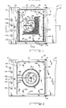
- Fig. 1 is an elevational view of the oven according to the present invention with the oven door shown in the open position;
- Fig. 2 is an elevational view of the oven of Fig. 1 with the oven door shown in the open position and with the screen and air deflector thereof removed;
- Fig. 3 is a view, in cross section, of the oven taken along line 3-3 of Fig. 1;
- Fig. 4 is a view, in cross-section, of the oven taken along line 4-4 of Fig. 1;
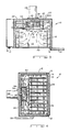
- Fig. 5 is an enlarged view of the fan and heater assembly of the oven of Fig. 1;
- Fig. 6 is a partial, enlarged, cross-sectional view of the slinger cup and water supply assembly of the oven taken along line 6-6 of Fig. 1;
- Fig. 7 is a schematic electrical diagram of the heater circuit for the oven of Fig. 1; and
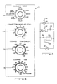
- Fig. 8 is an elevational view of the control panel for the oven of Fig. 1.
- Corresponding reference characters indicate corresponding parts throughout the several views of the drawings.
- The exemplifications set out herein illustrate a preferred embodiment of the invention, in one form thereof, and such exemplifications are not to be construed as limiting the scope of the disclosure or the scope of the invention in any manner.
- Referring to Figs. 1-4,
oven 10 is shown including anoven cabinet 12 having adoor 14 which is latched by means of alatch 13. Adoor 14 is supported on a pair ofhinges 15. Acontrol panel 16 is shown including a plurality ofcontrols 17A-17D mounted thereon for control of the oven. The oven includes acavity 18, a pair ofside walls top wall 21 and abottom wall 23. Walls 20-23 anddoor 14 of the cabinet are preferably insulated with insulation material which is inserted in the hollow space between the wall panels, as is conventional. A plurality of horizontally arrangedrails 24 are supported byvertical standoffs 25 which in turn are secured towalls Rails 24 support a plurality of trays (not shown) on which food items are supported for preparation in the oven. - Referring further to Figs. 1-4, a
fan 26 is rotatably mounted at the back portion of the oven cavity and including amotor 28 having arotatable motor shaft 30 secured to fan 26.Motor 28 is secured to backwall 32 ofoven 10 by means of a plurality ofbolts 34.Fan 26 is concentric with and is surrounded by a plurality ofheaters 36 which, in the preferred embodiment shown herein, comprise three axially spaced, generally circular heaters. These heaters are conventional in design and may be made of Calrod material. Asensor 38 is located inoven cavity 18 to provide an indication of the temperature of the air or steam inoven cavity 18 thereby enabling a control circuit to maintain the temperature of the air or steam inoven cavity 18 within selected temperature limits as further explained hereinafter. - A
deflector panel 40 is arranged inoven cavity 18 in front offan 26 andheaters 36.Deflector panel 40 is supported on plurality ofstandoffs 42 which in turn are supported on the oven backwall 32.Wing nuts 44secure panel 40 onstandoffs 42. A water supply comprising asmall tube 46 having anelbow portion 48 is arranged inoven cavity 18 with the outlet oftube 46 arranged substantially coaxially withshaft 30 ofmotor 28.Tube 46, by way of example, has a diameter in the range of 1/8 inch to 1/2 inch.Water supply tube 46 is connected to a conventional supply of water (not shown) for the supply of water tooven cavity 18. Thus, at a water supply pressure of 30-110 pounds per square inch,water supply tube 46 can continuously supply a quantity of 10-20 cubic inches of water per minute tooven cavity 18.Deflector panel 40 includes acircular opening 50 which is covered by means of ascreen 52 supported onscreen support brackets 54, four of which are shown in the disclosed embodiment. Thus, as best seen in Figs. 3 and 4, air or steam may be drawn axially intofan 26 throughopening 50 indeflector panel 40 and may then be moved radially outwardly byfan 26 acrossheaters 36, whereafter the air or steam is deflected bydeflector panel 40 and caused to flow alongside walls top wall 21 andbottom wall 23 ofoven 10 and over the foodstuffs (not shown) located on the support trays (not shown) and back tofan 26 throughopening 50. - By referring to Figs. 2, 5, and 6,
heaters 36 are shown to includeheater connector portions 60 for connecting the heaters to a source of electrical supply. Furthermore,fan 26 is mounted on afan hub 62 which in turn is secured tomotor shaft 30 and rotates therewith.Fan 26 is secured tohub 62 by means of a plurality ofrivets 64. Aslinger cup 66 is secured tomotor shaft 30 forwardly offan hub 62 by means of a threadedfastener 68.Cup 66 includes an interior surface which has an inverse taperedportion 70 to form aliquid retention volume 72 incup 66. Thus, whencup 66 is rotated withshaft 30, centrifugal force will cause water which flows fromwater supply tube 46 intoliquid retention volume 72 to be retained therein by means of centrifugal force. Thefront surface 75 ofcup 66 is generally vertical and is disposed at anangle 76 with respect to the inverse taperedsurface portion 70 thereby forming anedge 74.Angle 76 is preferably in the range of 70° to 85°. If water is continuously added tocup 66 while the cup rotates, the volume of water will overflow edge 74 of the cup.Edge 74 is preferably rather sharp so that only a thin layer of water will flow fromvolume 72 overedge 74. As the thin film or layer of water flows overedge 74, this water is spun off, or slung, outwardly in a thin sheet of water indicated at 78 by the operation of centrifugal force. This slinging action will cause the water to be atomized because of the relatively high speed with whichcup 66 rotates and the centrifugal forces acting on the thin sheet ofwater 78. The speed of rotation ofcup 66 is preferably in the range of 960 rpm to 3600 rpm. In a typical arrangement, the speed of rotation ofcup 66 is 1600 rpm. - The atomized particles of water will flow outwardly in a circular pattern, as best seen in Figs. 5 and 6, and will flow through
fan blades 82 offan 26 and acrossheaters 36 to be heated thereby, whereby the water particles will flash into steam. Since the droplets of moisture, as they are spun off fromslinger cup 66, are very small, thefan blades 82 offan 26 will not need to break up the droplets into an even finer mist. Furthermore, since the water droplets are substantially completely atomized when they flow acrossheaters 36, the transfer of thermal energy fromheaters 36 to the atomized water droplets is rapid so that the conversion of the atomized water to steam is very efficient and is readily accomplished. - Referring now to Figs. 7, an electrical schematic circuit diagram is shown for the operation of the oven. A source of alternating
electric voltage 86 is connected toheaters 36 by way of athermostat 84.Thermostat 84 also receives an input fromtemperature sensor 38.Thermostat 84 is conventional and may consist of an on/off bimetal switching arrangement wherebyheaters 36 will be turned off when the temperature of steam or air inoven cavity 18, as sensed bysensor 38, exceeds a certain level. When the temperature of the steam or air inoven cavity 18 drops below a certain level, as sensed bysensor 38,control 84 will switchheating elements 36 back into circuit with the electrical source ofsupply 86, thereby supplying further thermal energy tooven cavity 18 and raising the temperature thereof. - Also connected in parallel with
heaters 36 andthermostat 84 is atimer motor 90 including a cam (not shown) which controls the operation of aswitch 92 so thatswitch 92 is cyclically closed and opened.Switch 92 is connected in series with avalve 94 which in turn is connected in series withwater supply tube 46 to control the flow of water intocup 66.Timer 90 is selectively controlled by means of a control knob 96 so that the periods of time during which switch 92 is open may be varied. For instance,timer 90 may operate on a one minute cycle. With control knob 96 set at one end of its range, switch 92 will be continuously open. With control knob 96 set at the other end of its range, switch 92 will be continuously closed. With control knob 96 set between the extreme ends of its range, switch 92 will be opened for a predetermined portion of each minute during whichtimer 90 makes a complete revolution. Thus, knob 96 andtimer 90 comprise a cyclical control to cyclically operatevalve 94 for predetermined periods. Therefore, the amount of water supplied tocup 66 inoven cavity 18 may be controlled, as desired, by controlling the closure ofswitch 92 so that shots of water are cyclically added tooven cavity 18 when the oven operates in the moist hot air convection mode. Aswitch 93 bypasses switch 92 so thatvalve 94 may be continuously closed as desired. - Referring now to Fig. 8, the control panel for
oven 10 is shown in detail. Four control knobs, 17A, 17B, 17C, and 17D are provided.Control knob 17A controls the cooking mode which may be set for either a steam mode or a hot air convection mode. In the steam cooking mode, switch 93 is closed so that water is continuously supplied to the oven cavity for the continuous generation of steam. Two settings are provided in the steam cooking mode, namely a high steam setting and a low steam setting. In the low steam setting, the temperature of the steam is maintained to be in the range of 212°-220° In the high steam setting, the temperature of the steam is elevated and is maintained in the range of 250°-270°. The temperature of the steam in the steam mode is preset and is automatically maintained in these ranges by selecting either the high steam mode or the low steam mode and is not further controllable by means of temperature control knob 17c. In the steam mode, the fan speed is automatically set for high speed which, in the preferred embodiment, is 1600 rpm. - When the cooking
mode control knob 17A is set in the convection mode, the speed offan 26 may be selected to be high or low. In the preferred embodiment, the high speed setting of the fan is 1600 rpm and the low speed setting of the fan is 1200 rpm. Furthermore, in the convection cooking mode, the temperature of the oven cavity is selected by means of cookingtemperature control knob 17C which, in the illustrated embodiment, may be selected anywhere in the range of 100°F-550°F. In the convection cooking mode,control knob 17B is also enabled so that the convection moisture level may be selected. As explained hereinabove,control knob 17B controls the period of time for each revolution oftimer 90 during which switch 92 is closed.Switch 93 is open in the convection mode so thatswitch 92 is controlling. For the sake of convenience, the range of control forcontrol knob 17B has been divided into ten discrete control settings. Therefore, by selecting, for instance, setting 4 forcontrol knob 17B, switch 92 will be closed 4/10 of each period of revolution oftimer 90. Thus, the amount of water which will be added tooven cavity 18 may be controlled to be from 0-60 cubic inches per hour by the setting ofcontrol knob 17B. It may also be desired to cook some foods with dry air only. Thus,knob 17B may be adjusted to select the 0 setting. On the other hand, in certain modes of operation, it may be desired to have convection air with a high moisture content. For instance, if it is desired to glaze crusts or the like, it is desired to generate a moist atmosphere so that water vapor will condense on the food products to form a glazed crust. Thus,knob 17B will be adjusted to a higher setting. - The cooking mode control may also be set in the hold setting which will cause
oven cavity 18 to be maintained at a selected temperature and moisture level. During this mode,fan 26 is operated in the low speed operation. - Control knob, 17D, may be adjusted to control the amount of cooking time.
Knob 17D may also be adjusted to select continuous cooking so that the cooking cycle is not timed. - In operation, therefore, when it is desired to operate the oven in the steam mode,
control knob 17A will be set for either the high or the low temperature steam mode. Water will then be continuously supplied tocup 66 and will continuously cause steam to be developed inoven cavity 18 as explained hereinabove. As the water is converted to steam, a small amount of pressure will be developed inoven cavity 18 as the water flashes into steam. This pressure will cause air and some steam to be expelled fromoven cavity 18 throughdrain 33. By continuously generating steam,oven cavity 18 is soon purged of air so that a pure atmosphere of steam is maintained.Fan 26 continuously circulates the steam incavity 18. As some steam condenses on the food or oven walls, it will collect in the bottom ofcavity 18 and will be removed therefrom bydrain 33.Cavity 18 will thus be continuously operated at atmospheric pressure because any excess pressure which develops incavity 18 will cause more steam or air to be expelled throughdrain 33. Thus, fully saturated steam is continuously generated which causes food present inoven cavity 18 to be cooked quickly and efficiently. - It will be understood that, in the steam mode when the oven is initially turned on and if frozen food has been loaded into the oven, quite a large quantity of steam will be condensed so that the thermal energy supplied by
heaters 36 may not be sufficient to quickly create a super-heated steam atmosphere. However,heaters 36 are preferably relatively large, such as, for instance, 13,500 watts and, therefore, this condition will not last very long as the food is quickly heated up. - As explained hereinabove, steam or water vapor which condenses on the cooler food items will drip downwardly from the food items together with any moisture or juice which has cooked out of the food items. These drippings and condensed steam will flow downwardly to be collected in the bottom of the oven and to be discharged therefrom by
drain 33. Since all the condensed steam or water vapor and food juices are removed fromoven cavity 18 bydrain 33, no flavor from the food items will be redeposited on the food items to impart undesirable food flavors thereto.Drain 33, therefore, in addition to draining condensate and food juices from theoven cavity 18, will maintainoven cavity 18 at atmospheric pressure at all times. - In the convection mode,
control knob 17A is set for either high speed convection or low speed convection. Furthermore, by settingcontrol knob 17B, the moisture level inoven cavity 18 is selected and controlled. Since water is not continuously supplied tooven cavity 18 in this mode, only water vapor will be generated. Further, in this mode, some water vapor and air may also be expelled fromoven cavity 18 bydrain 33 as water vapor is generated. However, as some of the water vapor condenses on either the food or the walls ofoven cavity 18, a negative pressure is generated incavity 18 so that air may be drawn intooven cavity 18 in throughdrain 33 to mix with the air and water vapor which is present inoven cavity 18. In the convection mode,control knob 17C is set to select the desired cavity temperature. If it is desired to maintain food inoven cavity 18 at a selected temperature and moisture level,control knob 17A is set on hold and controlknobs - What has, therefore, been disclosed is an oven for rapidly and efficiently preparing food items with steam or convection hot air and wherein baked goods as well as vegetables, meats, and the like, including delicate items, may be prepared.
Claims (10)
- A steam and convection cooking oven for cooking foodstuffs, the oven comprisng: an oven cavity (18) at atmospheric pressure; a heater (36) disposed in said cavity for heating the cavity; a fan (26) for circulating air or steam in said cavity; water supply means (46) for supplying water to said cavity to be atomised by the fan and circulated in the cavity; temperature control means (84) are provided for controlling the temperature in said cavity and mode selection means (16) are provided for causing said cavity to be filled with either steam or convection air; characterised in that rotatable cup means (66) are provided for receiving water from said water supply means and for forming a sheet of water which is flung onto said fan to be atomised thereby.
- An oven as claimed in Claim 1, characterized in that selection of a steam atmosphere in said cavity (18) with said mode selection means (16) causes a continuous supply of water to said receiving means (66).
- An oven as claimed in Claim 1 or Claim 2, characterised in that said rotatable cup means has an edge portion (74) and an interior surface (70) which tapers inversely away from said edge portion whereby a volume of water will collect in said cup, and whereby a layer of said water will flow over said edge and will be atomized by centrifugal force.
- An oven as claimed in Claim 3, characterized in that the included angle between said edge portion (74) of said cup (66) and the interior surface of said cup is in the range of 70° to 85°.
- An oven as claimed in any of Claims 1 to 4, characterised in that said heater (36) surrounds said cup (66) whereby said atomized water is flashed into steam by said heater.
- An oven as claimed in any of the preceding claims, characterized in that said fan (26) is a radial flow fan concentrically mounted with said heater (36) whereby air or steam flows generally axially through said cavity toward said fan and then flows radially outwardly from said fan across said heater.
- An oven as claimed in any of the preceding claims, characterized by means for maintaining said oven cavity (18) at substantially atmospheric pressure comprising an open drain (33) for draining condensate from said cavity.
- An oven as claimed in any of the preceding claims, characterized by control means including a control setting for continuously supplying water to said slinger cup (66).
- A method for heating foodstuffs with steam utilising an oven (10), which includes an oven cavity (18), a heater (36), means (48) for supplying water to the oven cavity, means for forming a sheet of water and for atomizing the sheet of water in the oven cavity including a fan (26) for conducting the atomized water over the heater to generate steam and for circulating steam in the oven cavity, and means (84) for selectively controlling the heater; characterized in that the method comprises the steps of continuously supplying water to the interior of a rotatable cup (66) disposed in said oven, rotating the cup about an axis coincident with the axis of the mouth (74) of the cup causing the water to flow in a thin film (78) over the mouth and to be slung outwardly by centrifugal force in a substantially circular planar pattern causing the water to be atomized, the atomized water impacting on said fan (26) which conducts the water over the heater (36) and continuously converts the water to steam, the heater being controlled to maintain said oven cavity at a selected temperature.
- The method according to Claim 9, characterized in that the continuously supplied water is atomized by flowing said water in a film over a rotating, substantially circular, circumferential edge (74) of said cup whereby said film of water is dispersed in a substantially planar circular pattern and is atomized by centrifugal force.
Priority Applications (1)
| Application Number | Priority Date | Filing Date | Title |
|---|---|---|---|
| AT86308669T ATE74710T1 (en) | 1986-05-09 | 1986-11-06 | COMBINATION OF CONVECTION AND STEAM OVEN. |
Applications Claiming Priority (2)
| Application Number | Priority Date | Filing Date | Title |
|---|---|---|---|
| US861432 | 1986-05-09 | ||
| US06/861,432 US4700685A (en) | 1986-05-09 | 1986-05-09 | Combination convection and steamer oven |
Publications (3)
| Publication Number | Publication Date |
|---|---|
| EP0244538A2 EP0244538A2 (en) | 1987-11-11 |
| EP0244538A3 EP0244538A3 (en) | 1988-09-21 |
| EP0244538B1 true EP0244538B1 (en) | 1992-04-15 |
Family
ID=25335773
Family Applications (1)
| Application Number | Title | Priority Date | Filing Date |
|---|---|---|---|
| EP86308669A Expired - Lifetime EP0244538B1 (en) | 1986-05-09 | 1986-11-06 | Combination convection and steamer oven |
Country Status (12)
| Country | Link |
|---|---|
| US (1) | US4700685A (en) |
| EP (1) | EP0244538B1 (en) |
| JP (1) | JPH0637978B2 (en) |
| KR (1) | KR900005938B1 (en) |
| AT (1) | ATE74710T1 (en) |
| AU (1) | AU579040B2 (en) |
| BR (1) | BR8702139A (en) |
| CA (1) | CA1268513A (en) |
| DE (1) | DE3684913D1 (en) |
| ES (1) | ES2030663T3 (en) |
| MX (1) | MX167100B (en) |
| ZA (1) | ZA872261B (en) |
Cited By (3)
| Publication number | Priority date | Publication date | Assignee | Title |
|---|---|---|---|---|
| US6188045B1 (en) | 2000-04-03 | 2001-02-13 | Alto-Shaam, Inc. | Combination oven with three-stage water atomizer |
| DE10158425C1 (en) * | 2001-11-29 | 2003-09-11 | Neubauer Kurt Maschf | Cooking appliance with fan and water supply |
| DE20320174U1 (en) * | 2003-12-31 | 2005-05-04 | Fanta, Pavel, Dipl.-Ing. | Steam cooker, oven and microwave oven |
Families Citing this family (104)
| Publication number | Priority date | Publication date | Assignee | Title |
|---|---|---|---|---|
| DE8604451U1 (en) * | 1986-02-19 | 1986-04-30 | Eloma GmbH Bedarfsartikel zur Gemeinschaftsverpflegung, 8031 Gernlinden | Device for cooking food |
| DE3777281D1 (en) * | 1986-08-12 | 1992-04-16 | Vaporina Back Und Gefriergerae | METHOD AND DEVICE FOR REHEATING AND FINISHING FOODSTUFFS, IN PARTICULAR BAKED AND GRILLED GOODS. |
| US4835368A (en) * | 1987-11-27 | 1989-05-30 | Carter-Hoffmann Corporation | Food treatment cabinet with flash steamer |
| US4891498A (en) * | 1987-11-27 | 1990-01-02 | Carter-Hoffman Corporation | Food treatment cabinet with flash steamer |
| US5080087A (en) * | 1987-12-21 | 1992-01-14 | Gas Research Institute | Two burner bake, broil and steam gas oven |
| US4995313A (en) * | 1988-03-15 | 1991-02-26 | Welbilt Corporation | Cooking apparatus |
| DE8902903U1 (en) * | 1989-03-09 | 1989-08-10 | Lechmetall Landsberg Gmbh Edelstahlerzeugnisse, 8910 Landsberg, De | |
| IT1234689B (en) * | 1989-03-21 | 1992-05-26 | Zanussi Grandi Impianti Spa | FORCED CONVECTION COOKING OVEN |
| DE3915166A1 (en) * | 1989-05-09 | 1990-11-15 | Patzner Gmbh & Co | Steam cabinet with integral heat exchanger - has counter-current spiral water outlet and inlet formed in bottom of cabinet |
| US4954693A (en) * | 1989-07-11 | 1990-09-04 | Suga Test Instruments Co., Ltd. | Ventilation regulated hot air supplied constant temperature oven |
| CH677582A5 (en) * | 1989-08-03 | 1991-06-14 | Wuest Ernst Menu System | |
| US5014679A (en) * | 1989-09-18 | 1991-05-14 | Tecogen, Inc. | Gas fired combination convection-steam oven |
| DE4013595C2 (en) * | 1990-04-27 | 1993-10-28 | Eloma Gmbh | Steam cooking device |
| DE9007558U1 (en) * | 1990-04-27 | 1992-08-13 | Eloma Gmbh Bedarfsartikel Zur Gemeinschaftsverpflegung, 8031 Maisach, De | |
| DE4013594C2 (en) * | 1990-04-27 | 1994-10-20 | Eloma Gmbh | Steam cooking device |
| NL9001472A (en) * | 1990-06-27 | 1992-01-16 | Fri Jado Bv | APPARATUS FOR PREPARING MEAT OR THE LIKE. |
| US5139079A (en) * | 1990-07-26 | 1992-08-18 | General Electric Company | Dynamic mechanical analyzer having improved heat transfer |
| US5097754A (en) * | 1990-10-09 | 1992-03-24 | Ore-Ida Foods, Inc. | Automatic air cooking system for vending machines |
| IT1253692B (en) * | 1991-07-17 | 1995-08-22 | Zanussi Grandi Impianti Spa | STEAM GENERATION DEVICE FOR FOOD COOKING EQUIPMENT, SUCH AS COOKING OVENS OR SIMILAR. |
| US5767487A (en) * | 1992-03-17 | 1998-06-16 | Tippmann; Eugene R. | Subatmospheric pressure cooking device |
| US5235903A (en) * | 1992-03-17 | 1993-08-17 | Tippmann Eugene R | Subatmospheric pressure cook-and-hold steaming oven |
| IT1258073B (en) * | 1992-04-29 | 1996-02-20 | Zanussi Elettromecc | HUMIDITY MEASURING DEVICE FOR OVENS, IN PARTICULAR FOOD COOKING OVENS |
| AU666365B2 (en) * | 1992-04-30 | 1996-02-08 | Moffat Pty Limited | Electrically heated rotary baker's oven |
| DE69314636T2 (en) * | 1992-05-26 | 1998-04-09 | Vos Ind Pty Ltd | COOKER |
| US5313878A (en) * | 1992-06-22 | 1994-05-24 | Strait Jr Clifford C | Microwave ovenware apparatus, hydrating microwave ovens and microwave water purifier |
| US5368008A (en) * | 1992-10-09 | 1994-11-29 | Delaware Capital Formation, Inc. | Steamer apparatus |
| US5485780A (en) * | 1993-02-26 | 1996-01-23 | Food Automation Service Techniques, Inc. | Rotisserie oven |
| AU683868B2 (en) * | 1993-03-24 | 1997-11-27 | Moffat Pty Limited | Bakery equipment |
| US5530223A (en) * | 1993-08-05 | 1996-06-25 | Angelo Po Grandi Cucine S.P.A. | Convection and steam oven with a pre-atomizer |
| DE4341410A1 (en) * | 1993-12-04 | 1995-06-08 | Licentia Gmbh | Baking and roasting oven with a cooking space and a steam generator for the cooking space |
| ATE172525T1 (en) * | 1994-02-04 | 1998-11-15 | Jura Elektroapparate Ag | STEAM GENERATION DEVICE |
| DE4420821A1 (en) * | 1994-06-15 | 1995-12-21 | Bosch Siemens Hausgeraete | Oven for steaming |
| US5649476A (en) * | 1994-08-22 | 1997-07-22 | Production Engineered Designs, Inc. | Steam generator assembly and steam cooking appliances using same |
| US5632924A (en) * | 1994-10-26 | 1997-05-27 | H.J. Heinz Company | Muffin tray and process for baking muffins |
| US5515773A (en) * | 1995-02-16 | 1996-05-14 | The Rival Company | Steam oven |
| US5688422A (en) * | 1995-04-28 | 1997-11-18 | Henny Penny Corporation | Programmable fan control method and apparatus for use in a food oven |
| AU2022697A (en) * | 1996-03-12 | 1997-10-01 | Aktiebolaget Electrolux | A generator for steam |
| US5732614A (en) * | 1996-05-20 | 1998-03-31 | Delaware Capital Formation, Inc. | Food processing apparatus |
| FR2754334B1 (en) * | 1996-10-07 | 1998-12-18 | Bourgeois Prod Coop | STEAM OVEN AND FORCED CONVEXION |
| DE19731544A1 (en) * | 1997-07-23 | 1999-01-28 | Gaggenau Hausgeraete Gmbh | Steam oven with a steam generator unit |
| US5951901A (en) * | 1997-10-31 | 1999-09-14 | G.S. Blodgett Corp. | Steam control for combination oven and steamer |
| US5988154A (en) * | 1997-10-31 | 1999-11-23 | G.S. Blodgett Corporation | Combination steamer and convection oven with double doors |
| FR2775760B1 (en) * | 1998-03-09 | 2000-05-05 | Bourgeois Prod Coop | STEAM OVEN WITH FIXED SPRAY OF SPRAY WATER |
| US6100502A (en) * | 1998-10-28 | 2000-08-08 | Wing Shing Products (Bvi) Co. Ltd. | Toaster oven with steam |
| US6124572A (en) * | 1999-09-21 | 2000-09-26 | Spilger; Jon Barton | Food warmer cabinet having an improved drawer slide assembly |
| DE10017966C2 (en) * | 2000-04-12 | 2003-12-04 | Rational Ag | Device and method for cleaning a cooking appliance interior |
| JP2001304555A (en) * | 2000-04-20 | 2001-10-31 | Fujimak Corp | Vapor generating mechanism in cooking oven |
| US6481433B1 (en) | 2000-11-17 | 2002-11-19 | Middleby Marshall Incorporated | Conveyor oven having an energy management system for a modulated gas flow |
| AU2002336448A1 (en) * | 2001-09-07 | 2003-03-24 | Alto-Shaam, Inc. | Humidity control system for combination oven |
| US6592364B2 (en) | 2001-11-30 | 2003-07-15 | David Zapata | Apparatus, method and system for independently controlling airflow in a conveyor oven |
| NZ535478A (en) * | 2002-03-27 | 2006-03-31 | Enodis Corp | Conveyorized oven with moisture laden air impingement and method |
| AU2003222089A1 (en) * | 2002-03-27 | 2003-10-13 | The Garland Group | Convection oven with laminar airflow and method |
| KR100439741B1 (en) * | 2002-06-14 | 2004-07-12 | 대영제과제빵기계공업주식회사 | Convection ovens |
| KR100528293B1 (en) * | 2002-11-15 | 2005-11-15 | 삼성전자주식회사 | Microwave oven and cleaning control method thereof |
| US6619189B1 (en) * | 2002-12-09 | 2003-09-16 | Thermodyne Food Service Product, Inc. | Food rethermalizing, cooking and holding apparatus and method |
| US20070006865A1 (en) | 2003-02-21 | 2007-01-11 | Wiker John H | Self-cleaning oven |
| EP1659911B1 (en) | 2003-08-08 | 2008-10-15 | Alto-Shaam, Inc. | Oven including smoking assembly in combination with one or more additional food preparation assemblies |
| JP3835804B2 (en) * | 2004-02-10 | 2006-10-18 | 松下電器産業株式会社 | Cooking device and cooking method |
| JP3827013B2 (en) * | 2004-03-19 | 2006-09-27 | シャープ株式会社 | Steam cooker |
| US9585400B2 (en) | 2004-03-23 | 2017-03-07 | The Middleby Corporation | Conveyor oven apparatus and method |
| US8087407B2 (en) | 2004-03-23 | 2012-01-03 | Middleby Corporation | Conveyor oven apparatus and method |
| US20060112947A1 (en) * | 2004-11-29 | 2006-06-01 | Atul Saksena | Steam cooker with moving steam delivery member |
| WO2006097016A1 (en) * | 2005-03-15 | 2006-09-21 | Guangdong Ge Lan Shi Group Co. Ltd. | An electric steaming oven with a device for rapidly discharging the steam |
| US7721797B2 (en) * | 2005-04-25 | 2010-05-25 | Be Intellectual Property, Inc. | Refrigerator-oven combination for an aircraft galley food service system |
| US20060251784A1 (en) * | 2005-05-03 | 2006-11-09 | Sells Joel M | Method for cooking meat using steam |
| US20060251785A1 (en) | 2005-05-06 | 2006-11-09 | Stefania Fraccon | Method for cooking food using steam |
| US20070175884A1 (en) * | 2006-01-31 | 2007-08-02 | Atul Saksena | Steam cooker with steam delivery device |
| US20070204855A1 (en) * | 2006-02-10 | 2007-09-06 | Jason Cheng | Steam system for continuous cleaning of hood fans |
| US7867534B2 (en) | 2006-10-18 | 2011-01-11 | Whirlpool Corporation | Cooking appliance with steam generator |
| EP1975516B1 (en) * | 2007-03-29 | 2012-05-02 | Electrolux Home Products Corporation N.V. | Cooking oven and method for operating the same |
| US7841104B2 (en) * | 2007-11-02 | 2010-11-30 | Steris Inc. | Method and apparatus for drying objects in a washer |
| US8207477B2 (en) * | 2007-11-26 | 2012-06-26 | Whirlpool Corporation | Method for cooking vegetables using steam |
| US8006684B2 (en) * | 2007-12-10 | 2011-08-30 | Star Comgistic Capital Co. Ltd. | Superheated steam grill |
| WO2009089381A2 (en) * | 2008-01-09 | 2009-07-16 | Unified Brands, Inc. | Boilerless combination convection steamer oven |
| CN103329951A (en) | 2008-01-28 | 2013-10-02 | 杜克制造公司 | Convection oven |
| US20100178407A1 (en) * | 2008-12-31 | 2010-07-15 | Rizzuto Leandro P | Oven and method for cooking with dry heat and steam heat |
| WO2010083387A2 (en) * | 2009-01-16 | 2010-07-22 | Mag Aerospace Industries, Inc. | Oven steam generator systems and methods |
| DE102009026500B3 (en) * | 2009-05-27 | 2011-02-24 | Miwe Michael Wenz Gmbh | proofer |
| US8839714B2 (en) | 2009-08-28 | 2014-09-23 | The Middleby Corporation | Apparatus and method for controlling a conveyor oven |
| EP2338390A1 (en) * | 2009-12-28 | 2011-06-29 | Koninklijke Philips Electronics N.V. | Low temperature steaming functionality - power steering |
| JP5186511B2 (en) * | 2010-01-08 | 2013-04-17 | 株式会社コメットカトウ | Steam convection oven |
| DE202010000123U1 (en) | 2010-02-04 | 2010-04-15 | Rational Ag | Humidifier and food processor |
| US20110301527A1 (en) * | 2010-06-04 | 2011-12-08 | Alvin Stewart Ostrow | Moist Heat Drug Delivery Apparatus and Method |
| US20140234793A1 (en) * | 2010-06-04 | 2014-08-21 | Alvin Stewart Ostrow | Moist heat drug delivery apparatus and method |
| WO2012112704A2 (en) * | 2011-02-15 | 2012-08-23 | Duke Manufacturing Co. | Holding oven |
| CN104411174A (en) * | 2012-03-28 | 2015-03-11 | B/E航空公司 | Vehicle oven having an optimized water vapor injector |
| CA2867157C (en) * | 2012-03-29 | 2017-01-24 | B/E Aerospace, Inc. | Vehicle oven having optimized airflow |
| DE102012220812B4 (en) | 2012-11-14 | 2017-09-28 | Miwe Michael Wenz Gmbh | Water supply for steam generator |
| US10918112B2 (en) | 2013-05-23 | 2021-02-16 | Duke Manufacturing Co. | Dough preparation apparatus and methods |
| WO2014190274A1 (en) | 2013-05-23 | 2014-11-27 | Duke Manufacturing Co. | Food preparation apparatus and methods |
| DE102013112150B4 (en) * | 2013-11-05 | 2023-07-06 | Rational Aktiengesellschaft | Process for baking small products using high energy input |
| JP2017531463A (en) * | 2014-10-23 | 2017-10-26 | コーニンクレッカ フィリップス エヌ ヴェKoninklijke Philips N.V. | Apparatus and method for cooking food |
| US10969118B2 (en) | 2016-05-26 | 2021-04-06 | Electrolux Home Products, Inc. | Steam cooking appliance |
| DE102016215650A1 (en) * | 2016-08-19 | 2018-02-22 | BSH Hausgeräte GmbH | Haushaltsgargerät |
| CA3083194A1 (en) | 2017-11-22 | 2019-05-31 | Hdl Therapeutics, Inc. | Systems and methods for priming fluid circuits of a plasma processing system |
| CA3087207A1 (en) | 2017-12-28 | 2019-07-04 | Hdl Therapeutics, Inc. | Methods for preserving and administering pre-beta high density lipoprotein extracted from human plasma |
| US11835239B2 (en) * | 2018-03-29 | 2023-12-05 | Aha, Llc | Process and apparatus for cooking utilizing nebulized water particles and air |
| US10966432B2 (en) * | 2018-03-29 | 2021-04-06 | Aha, Llc | Process and apparatus for cooking utilizing nebulized water particles and air |
| PL3770511T3 (en) * | 2019-07-24 | 2022-12-19 | Bonferraro S.P.A. | Electric convection cooking oven |
| CN111227669B (en) * | 2020-01-14 | 2022-10-04 | 宁波方太厨具有限公司 | Inner container structure and oven with same |
| CA3173324A1 (en) * | 2020-03-19 | 2021-09-23 | Illinois Tool Works Inc. | Convection oven |
| US11134808B2 (en) | 2020-03-30 | 2021-10-05 | Sharkninja Operating Llc | Cooking device and components thereof |
| CN114246460B (en) * | 2020-09-21 | 2023-04-21 | 佛山市顺德区美的电热电器制造有限公司 | Cooking appliance, control method, control device, and computer-readable storage medium |
| CN112336178B (en) * | 2020-11-27 | 2021-08-31 | 广东顺德融方电器有限公司 | Integral door plant steam oven |
Family Cites Families (61)
| Publication number | Priority date | Publication date | Assignee | Title |
|---|---|---|---|---|
| US1532086A (en) * | 1925-03-31 | Pliance co | ||
| US369836A (en) * | 1887-09-13 | blackman | ||
| US2636969A (en) * | 1953-04-28 | Bun warmer | ||
| US976252A (en) * | 1910-02-24 | 1910-11-22 | Fannie M Delaih | Cooking device. |
| US1349130A (en) * | 1916-03-04 | 1920-08-10 | Jr William S Hadaway | Heating apparatus |
| US1651509A (en) * | 1921-11-25 | 1927-12-06 | Brims James Alexander | Combination dry and steam heating apparatus |
| US1814122A (en) * | 1929-02-05 | 1931-07-14 | Erie Restaurant Equipment Comp | Cooker |
| US2218625A (en) * | 1939-04-04 | 1940-10-22 | Standard Oil Dev Co | Steam spray sweeper |
| US2490076A (en) * | 1945-09-18 | 1949-12-06 | Foremost Dairies Inc | Electric oven |
| US2617349A (en) * | 1949-08-01 | 1952-11-11 | Maynard W Tucker | Freshening apparatus for baked food |
| US3077530A (en) * | 1959-05-06 | 1963-02-12 | Gen Electric | Cooking appliance |
| US3069994A (en) * | 1959-07-29 | 1962-12-25 | Albert M Lewis | Food steamer |
| US3066213A (en) * | 1960-10-31 | 1962-11-27 | Webber Owen | Oven for reconstituting frozen food |
| US3191518A (en) * | 1962-06-11 | 1965-06-29 | Toastswell Co Inc | Food freshening apparatus |
| US3192167A (en) * | 1962-09-20 | 1965-06-29 | Ogawa Abiko | Low pressure liquid vaporizer which is electrically heated |
| US3320945A (en) * | 1964-11-12 | 1967-05-23 | Robert L Dunkelman | Steam cabinet for food products |
| US3502065A (en) * | 1968-05-03 | 1970-03-24 | Rush E Lassiter | Steam heating device |
| CH522389A (en) * | 1970-03-26 | 1972-06-30 | Therma Ag | Method for operating a convection oven for large kitchens, especially in the hospitality industry and in canteens, as well as convection oven for carrying out the method |
| US3820524A (en) * | 1970-06-08 | 1974-06-28 | R Buckell | Cooking ovens |
| US3677171A (en) * | 1970-07-24 | 1972-07-18 | P Le Van Wayne | Apparatus for cooking strips of meat |
| US3735749A (en) * | 1970-11-04 | 1973-05-29 | To Restaurant Technology Inc | Bun steamer injector |
| US3774008A (en) * | 1971-03-03 | 1973-11-20 | T Maniscalco | Steam generating apparatus |
| US3639725A (en) * | 1971-03-03 | 1972-02-01 | Thomas J Maniscalco | Steam-generating apparatus |
| US3736860A (en) * | 1971-04-06 | 1973-06-05 | Vischer Products Co | Infrared cooking apparatus |
| CA929369A (en) * | 1971-08-03 | 1973-07-03 | M. Bardeau William | Devices for heating or cooking foods |
| GB1359294A (en) * | 1971-08-12 | 1974-07-10 | Jones F J | Toast warmer |
| US3732396A (en) * | 1971-09-13 | 1973-05-08 | J Tucker | Steam vessel food warmer |
| US3731614A (en) * | 1971-12-17 | 1973-05-08 | D Smith | Apparatus for cooking food products |
| US3794016A (en) * | 1972-04-03 | 1974-02-26 | Restaurant Technology | Steam injector and spatula |
| US3902044A (en) * | 1972-11-20 | 1975-08-26 | Schick Inc | Electrically heated towel steaming appliance |
| US3908533A (en) * | 1973-04-04 | 1975-09-30 | Electrolux Ab | Apparatus for continuously cooking food in sequential oven section of an elongated oven |
| US3814901A (en) * | 1973-05-07 | 1974-06-04 | Lincoln Mfg Co | Steam heating device |
| JPS5010944A (en) * | 1973-05-26 | 1975-02-04 | ||
| IT1024113B (en) * | 1974-05-18 | 1978-06-20 | Zanussi Grandi | FORCED CONVENTION FORROOM |
| US4011805A (en) * | 1975-02-19 | 1977-03-15 | Alco Standard Corporation | Convection steamer apparatus and method for processing food items or the like |
| US4010349A (en) * | 1975-02-27 | 1977-03-01 | Lincoln Manufacturing Company, Inc. | Proofing cabinet |
| US4039776A (en) * | 1975-09-19 | 1977-08-02 | National Equipment Corporation | Closed passage heat holding apparatus |
| US4409453A (en) * | 1976-05-19 | 1983-10-11 | Smith Donald P | Combined microwave and impingement heating apparatus |
| US4154861A (en) * | 1976-05-19 | 1979-05-15 | Smith Donald P | Heat treatment of food products |
| US4366749A (en) * | 1976-06-21 | 1983-01-04 | Heat And Control, Inc. | Apparatus for processing food products |
| SE394941B (en) * | 1976-09-08 | 1977-07-25 | Platslageriet Rostfri Ab | ANGUPPVERMD KOKGRYTA |
| US4121509A (en) * | 1977-01-10 | 1978-10-24 | N.P.I. Corporation | Controlled atmosphere broiler |
| JPS5710323Y2 (en) * | 1977-06-15 | 1982-02-27 | ||
| SE408256C (en) * | 1977-11-29 | 1981-07-02 | Tipe Revent Ab | CONVECTION OVEN WITH WATER-IRRIGABLE, ACCUMULATED HEAT BODY |
| US4173215A (en) * | 1977-12-05 | 1979-11-06 | Mscan Metal Canada Limitee | Apparatus for steaming foods |
| US4123969A (en) * | 1977-12-23 | 1978-11-07 | Abbate Warren J | Yeast raising baking appliance |
| FR2413035B1 (en) * | 1977-12-30 | 1985-07-05 | Scheyen Marcel | IMPROVEMENTS IN ELECTRIC BAKERY, PASTRY OVEN, OR THE LIKE |
| CH630240A5 (en) * | 1978-06-22 | 1982-06-15 | Electrolux Ag | Hot-air circulating, baking, frying and grilling oven, and method of operating it |
| US4367724A (en) * | 1979-11-16 | 1983-01-11 | Willett Paul E | Baker's ovens |
| US4264539A (en) * | 1979-12-12 | 1981-04-28 | Samuel Ray Dickenson | Liquid fuel vaporizer |
| US4343292A (en) * | 1980-02-21 | 1982-08-10 | Groen Division/Dover Corporation | Vapor jacketed cooking vessel |
| US4495932A (en) * | 1981-02-03 | 1985-01-29 | Lincoln Manufacturing Company, Inc. | Food steam heating apparatus |
| US4436082A (en) * | 1981-10-29 | 1984-03-13 | Hiller Jeffrey H | Assembly for steam heating or cooking food products and its method of operation |
| DE8131827U1 (en) * | 1981-10-31 | 1983-04-14 | Meister, Siegfried, 8910 Landsberg | DEVICE FOR HEAT-TREATING FOODSTUFFS BY MEANS OF A VAPOR-AIR MIXTURE |
| FR2516351B1 (en) * | 1981-11-13 | 1987-01-16 | Dumont Sa | AIR CONVECTION COMBUSTION OVEN, ESPECIALLY FOR BAKERY-PASTRY |
| US4438572A (en) * | 1982-06-09 | 1984-03-27 | Lincoln Manufacturing Co., Inc. | Heat duct support assembly for a food preparation oven and method |
| US4462383A (en) * | 1982-06-09 | 1984-07-31 | Lincoln Manufacturing Company, Inc. | Impingement food preparation apparatus |
| JPS58194747U (en) * | 1982-06-18 | 1983-12-24 | 大畠 隆 | processed food storage |
| US4467783A (en) * | 1983-02-04 | 1984-08-28 | Thermo Electron Corporation | Radiant/jet impingement gas-fired cooking kettle |
| GB2146222B (en) * | 1983-09-08 | 1987-04-15 | Peter Edward Cranage | Bakery oven |
| US4587946A (en) * | 1985-02-01 | 1986-05-13 | Jacques Doyon | Mobile baking oven and proofer |
-
1986
- 1986-05-09 US US06/861,432 patent/US4700685A/en not_active Expired - Lifetime
- 1986-11-06 DE DE8686308669T patent/DE3684913D1/en not_active Expired - Lifetime
- 1986-11-06 EP EP86308669A patent/EP0244538B1/en not_active Expired - Lifetime
- 1986-11-06 AT AT86308669T patent/ATE74710T1/en not_active IP Right Cessation
- 1986-11-06 ES ES198686308669T patent/ES2030663T3/en not_active Expired - Lifetime
-
1987
- 1987-03-19 CA CA000532531A patent/CA1268513A/en not_active Expired - Lifetime
- 1987-03-23 AU AU70539/87A patent/AU579040B2/en not_active Ceased
- 1987-03-27 KR KR1019870002858A patent/KR900005938B1/en not_active IP Right Cessation
- 1987-03-27 ZA ZA872261A patent/ZA872261B/en unknown
- 1987-04-14 JP JP62089995A patent/JPH0637978B2/en not_active Expired - Lifetime
- 1987-04-30 BR BR8702139A patent/BR8702139A/en unknown
- 1987-05-07 MX MX006387A patent/MX167100B/en unknown
Cited By (3)
| Publication number | Priority date | Publication date | Assignee | Title |
|---|---|---|---|---|
| US6188045B1 (en) | 2000-04-03 | 2001-02-13 | Alto-Shaam, Inc. | Combination oven with three-stage water atomizer |
| DE10158425C1 (en) * | 2001-11-29 | 2003-09-11 | Neubauer Kurt Maschf | Cooking appliance with fan and water supply |
| DE20320174U1 (en) * | 2003-12-31 | 2005-05-04 | Fanta, Pavel, Dipl.-Ing. | Steam cooker, oven and microwave oven |
Also Published As
| Publication number | Publication date |
|---|---|
| AU7053987A (en) | 1987-12-10 |
| DE3684913D1 (en) | 1992-05-21 |
| EP0244538A3 (en) | 1988-09-21 |
| KR870010834A (en) | 1987-12-18 |
| US4700685A (en) | 1987-10-20 |
| ES2030663T3 (en) | 1992-11-16 |
| CA1268513A (en) | 1990-05-01 |
| BR8702139A (en) | 1988-02-09 |
| EP0244538A2 (en) | 1987-11-11 |
| AU579040B2 (en) | 1988-11-10 |
| MX167100B (en) | 1993-03-04 |
| JPH0637978B2 (en) | 1994-05-18 |
| ZA872261B (en) | 1987-11-25 |
| KR900005938B1 (en) | 1990-08-18 |
| JPS62262953A (en) | 1987-11-16 |
| ATE74710T1 (en) | 1992-05-15 |
Similar Documents
| Publication | Publication Date | Title |
|---|---|---|
| EP0244538B1 (en) | Combination convection and steamer oven | |
| CA1196790A (en) | Convection food heating | |
| US4581989A (en) | Convection food heating | |
| US6555791B2 (en) | Oven and an oven control method | |
| IE47952B1 (en) | Appliance for cooking of heating foodstuff | |
| US3212426A (en) | Apparatus for cooking | |
| WO2005090866A1 (en) | Steam cooking apparatus | |
| CN111700511B (en) | Control method of cooking apparatus, and storage medium | |
| CA2393872A1 (en) | High speed variable size toaster | |
| US7601932B2 (en) | Oven | |
| EP0463657B1 (en) | Appliance for the preparation of meat or similar products | |
| JP3864990B2 (en) | Combined cooker | |
| JPH06272866A (en) | Composite type heating device | |
| AU3840495A (en) | Process for preparing foodstuffs in a hot air oven | |
| JPS596162Y2 (en) | High frequency heating device | |
| JPH094848A (en) | Combined cooker | |
| JP3575080B2 (en) | Combined cooking range | |
| CN116784676A (en) | Control method and device for air fryer, air fryer and readable storage medium | |
| RU2220517C2 (en) | Device for heating and processing various materials | |
| JP3867714B2 (en) | Combined cooker | |
| JPH0143214B2 (en) | ||
| JP2012241927A (en) | Heating cooker | |
| JP2004144414A (en) | Food heating method and food heating device |
Legal Events
| Date | Code | Title | Description |
|---|---|---|---|
| PUAI | Public reference made under article 153(3) epc to a published international application that has entered the european phase |
Free format text: ORIGINAL CODE: 0009012 |
|
| AK | Designated contracting states |
Kind code of ref document: A2 Designated state(s): AT BE CH DE ES FR GB GR IT LI LU NL SE |
|
| 17P | Request for examination filed |
Effective date: 19871210 |
|
| PUAL | Search report despatched |
Free format text: ORIGINAL CODE: 0009013 |
|
| RHK1 | Main classification (correction) |
Ipc: A21B 3/04 |
|
| AK | Designated contracting states |
Kind code of ref document: A3 Designated state(s): AT BE CH DE ES FR GB GR IT LI LU NL SE |
|
| RAP1 | Party data changed (applicant data changed or rights of an application transferred) |
Owner name: LINCOLN FOODSERVICE PRODUCTS, INC. |
|
| 17Q | First examination report despatched |
Effective date: 19900706 |
|
| ITTA | It: last paid annual fee | ||
| GRAA | (expected) grant |
Free format text: ORIGINAL CODE: 0009210 |
|
| AK | Designated contracting states |
Kind code of ref document: B1 Designated state(s): AT BE CH DE ES FR GB GR IT LI LU NL SE |
|
| PG25 | Lapsed in a contracting state [announced via postgrant information from national office to epo] |
Ref country code: GR Free format text: LAPSE BECAUSE OF FAILURE TO SUBMIT A TRANSLATION OF THE DESCRIPTION OR TO PAY THE FEE WITHIN THE PRESCRIBED TIME-LIMIT Effective date: 19920415 Ref country code: BE Effective date: 19920415 Ref country code: AT Effective date: 19920415 |
|
| REF | Corresponds to: |
Ref document number: 74710 Country of ref document: AT Date of ref document: 19920515 Kind code of ref document: T |
|
| RAP2 | Party data changed (patent owner data changed or rights of a patent transferred) |
Owner name: ELOMA GMBH BEDARFSARTIKEL ZUR GEMEINSCHAFTSVERPFLE |
|
| REF | Corresponds to: |
Ref document number: 3684913 Country of ref document: DE Date of ref document: 19920521 |
|
| ET | Fr: translation filed | ||
| ITF | It: translation for a ep patent filed |
Owner name: STUDIO TORTA SOCIETA' SEMPLICE |
|
| REG | Reference to a national code |
Ref country code: ES Ref legal event code: FG2A Ref document number: 2030663 Country of ref document: ES Kind code of ref document: T3 |
|
| PG25 | Lapsed in a contracting state [announced via postgrant information from national office to epo] |
Ref country code: LU Free format text: LAPSE BECAUSE OF NON-PAYMENT OF DUE FEES Effective date: 19921130 |
|
| BECN | Be: change of holder's name |
Effective date: 19920415 |
|
| PLBE | No opposition filed within time limit |
Free format text: ORIGINAL CODE: 0009261 |
|
| STAA | Information on the status of an ep patent application or granted ep patent |
Free format text: STATUS: NO OPPOSITION FILED WITHIN TIME LIMIT |
|
| 26N | No opposition filed | ||
| PGFP | Annual fee paid to national office [announced via postgrant information from national office to epo] |
Ref country code: SE Payment date: 19931025 Year of fee payment: 8 |
|
| PGFP | Annual fee paid to national office [announced via postgrant information from national office to epo] |
Ref country code: GB Payment date: 19931029 Year of fee payment: 8 |
|
| PGFP | Annual fee paid to national office [announced via postgrant information from national office to epo] |
Ref country code: ES Payment date: 19931112 Year of fee payment: 8 |
|
| PGFP | Annual fee paid to national office [announced via postgrant information from national office to epo] |
Ref country code: CH Payment date: 19931123 Year of fee payment: 8 |
|
| PGFP | Annual fee paid to national office [announced via postgrant information from national office to epo] |
Ref country code: NL Payment date: 19931130 Year of fee payment: 8 Ref country code: FR Payment date: 19931130 Year of fee payment: 8 |
|
| PG25 | Lapsed in a contracting state [announced via postgrant information from national office to epo] |
Ref country code: GB Effective date: 19941106 |
|
| PG25 | Lapsed in a contracting state [announced via postgrant information from national office to epo] |
Ref country code: SE Effective date: 19941107 Ref country code: ES Free format text: LAPSE BECAUSE OF EXPIRATION OF PROTECTION Effective date: 19941107 |
|
| PG25 | Lapsed in a contracting state [announced via postgrant information from national office to epo] |
Ref country code: LI Effective date: 19941130 Ref country code: CH Effective date: 19941130 |
|
| EAL | Se: european patent in force in sweden |
Ref document number: 86308669.0 |
|
| PG25 | Lapsed in a contracting state [announced via postgrant information from national office to epo] |
Ref country code: NL Effective date: 19950601 |
|
| GBPC | Gb: european patent ceased through non-payment of renewal fee |
Effective date: 19941106 |
|
| NLV4 | Nl: lapsed or anulled due to non-payment of the annual fee | ||
| PG25 | Lapsed in a contracting state [announced via postgrant information from national office to epo] |
Ref country code: FR Effective date: 19950731 |
|
| REG | Reference to a national code |
Ref country code: CH Ref legal event code: PL |
|
| EUG | Se: european patent has lapsed |
Ref document number: 86308669.0 |
|
| REG | Reference to a national code |
Ref country code: FR Ref legal event code: ST |
|
| REG | Reference to a national code |
Ref country code: ES Ref legal event code: FD2A Effective date: 20010301 |
|
| PGFP | Annual fee paid to national office [announced via postgrant information from national office to epo] |
Ref country code: IT Payment date: 20050427 Year of fee payment: 20 |
|
| PGFP | Annual fee paid to national office [announced via postgrant information from national office to epo] |
Ref country code: DE Payment date: 20060130 Year of fee payment: 20 |