EP0244827A2 - Improved optical head - Google Patents
Improved optical head Download PDFInfo
- Publication number
- EP0244827A2 EP0244827A2 EP87106503A EP87106503A EP0244827A2 EP 0244827 A2 EP0244827 A2 EP 0244827A2 EP 87106503 A EP87106503 A EP 87106503A EP 87106503 A EP87106503 A EP 87106503A EP 0244827 A2 EP0244827 A2 EP 0244827A2
- Authority
- EP
- European Patent Office
- Prior art keywords
- laser
- medium
- lens
- photodetector
- diffracted
- Prior art date
- Legal status (The legal status is an assumption and is not a legal conclusion. Google has not performed a legal analysis and makes no representation as to the accuracy of the status listed.)
- Withdrawn
Links
Images


Classifications
-
- G—PHYSICS
- G11—INFORMATION STORAGE
- G11B—INFORMATION STORAGE BASED ON RELATIVE MOVEMENT BETWEEN RECORD CARRIER AND TRANSDUCER
- G11B7/00—Recording or reproducing by optical means, e.g. recording using a thermal beam of optical radiation by modifying optical properties or the physical structure, reproducing using an optical beam at lower power by sensing optical properties; Record carriers therefor
- G11B7/12—Heads, e.g. forming of the optical beam spot or modulation of the optical beam
- G11B7/135—Means for guiding the beam from the source to the record carrier or from the record carrier to the detector
- G11B7/1353—Diffractive elements, e.g. holograms or gratings
-
- G—PHYSICS
- G11—INFORMATION STORAGE
- G11B—INFORMATION STORAGE BASED ON RELATIVE MOVEMENT BETWEEN RECORD CARRIER AND TRANSDUCER
- G11B11/00—Recording on or reproducing from the same record carrier wherein for these two operations the methods are covered by different main groups of groups G11B3/00 - G11B7/00 or by different subgroups of group G11B9/00; Record carriers therefor
- G11B11/10—Recording on or reproducing from the same record carrier wherein for these two operations the methods are covered by different main groups of groups G11B3/00 - G11B7/00 or by different subgroups of group G11B9/00; Record carriers therefor using recording by magnetic means or other means for magnetisation or demagnetisation of a record carrier, e.g. light induced spin magnetisation; Demagnetisation by thermal or stress means in the presence or not of an orienting magnetic field
- G11B11/105—Recording on or reproducing from the same record carrier wherein for these two operations the methods are covered by different main groups of groups G11B3/00 - G11B7/00 or by different subgroups of group G11B9/00; Record carriers therefor using recording by magnetic means or other means for magnetisation or demagnetisation of a record carrier, e.g. light induced spin magnetisation; Demagnetisation by thermal or stress means in the presence or not of an orienting magnetic field using a beam of light or a magnetic field for recording by change of magnetisation and a beam of light for reproducing, i.e. magneto-optical, e.g. light-induced thermomagnetic recording, spin magnetisation recording, Kerr or Faraday effect reproducing
- G11B11/10532—Heads
-
- G—PHYSICS
- G11—INFORMATION STORAGE
- G11B—INFORMATION STORAGE BASED ON RELATIVE MOVEMENT BETWEEN RECORD CARRIER AND TRANSDUCER
- G11B7/00—Recording or reproducing by optical means, e.g. recording using a thermal beam of optical radiation by modifying optical properties or the physical structure, reproducing using an optical beam at lower power by sensing optical properties; Record carriers therefor
- G11B7/12—Heads, e.g. forming of the optical beam spot or modulation of the optical beam
- G11B7/123—Integrated head arrangements, e.g. with source and detectors mounted on the same substrate
Definitions
- the present invention relates to optical heads for use in data recording and retrieval systems.
- Optical heads produce a focused beam of light on a medium containing information and detect the light reflected from the medium to determine the information content of the medium.
- Mechanisms for maintaining the focus and tracking of the optical head are required.
- the compact audio disc player is a significant example of how lasers are used in playing back prerecorded music, which is a form of information.
- the concept of the compact audio disc player or the long play video disc player can be applied to the storage of data for a large computer network, mini computers or even personal computers.
- the optical unit is separated into two parts.
- the first part contains a laser and a collimating lens to produce a nearly collimated (parallel) laser beam. It also contains.a beam-splitter to direct the return light reflected off the medium to a detector reading the recorded information.
- the second part contains a focusing objective lens and a mechanism for moving it up and down so that the focus spot is maintained on the medium surface.
- a laser beam from the laser diode is directly imaged onto the medium by an objective lens without the use of a collimater.
- the light is imaged on a detector by a beam-splitter.
- FIG. 1 shows one embodiment of a prior art optical read head for a compact disc player.
- the head consists of a laser pen 10 and a focusing and tracking actuator 12.
- the laser beam is focused on an information medium 14 at a spot 16.
- a laser beam 18 in the shape of an elliptical cone is emitted from the semiconductor laser diode 20.
- Laser beam 18 passes unchanged through a beam-splitter 22 to a collimating lens 24.
- Collimating lens 24 produces a substantially parallel beam of light 26 which impinges upon an objective lens 28.
- Objective lens 28 focuses beam 26 onto medium 14 at spot 16.
- the focusing of lens 28 is accomplished through the use of a magnetic coil 30 which moves objective lens 28 up and down with respect to medium 14.
- a tracking actuator 12 may move-objective lens 28 radially along the direction of medium 14, which is typically a disc.
- Figure 2 illustrates another embodiment of a prior art optical head.
- a laser diode 36 emits a diverging laser beam 38 which passes through a beam-splitter 40 directly onto an objective lens 42.
- lens 42 is mounted in a focusing and tracking actuator 44 which includes a coil 46.
- the beam impinges upon a medium 48 and a portion of the reflected beam is directed by beam-splitter 40 through biprism 50 onto photodetector 52.
- This embodiment eliminates the need for collimating lens 24 of Figure 1, but requires that the laser pen and focus and tracking actuator of Figure 1 be combined in one unit because of the need to precisely align objective lens 42 and beam-splitter 40.
- the embodiment of Figure 2 cannot be produced modularly as can the embodiment of Figure 1.
- a third prior art optical head utilizing a pair of hologram lenses is shown in Figure 3.
- a hologram lens is a diffraction grating which was produced using holographic methods.
- a diffraction grating is a grating having a series of slits so that it diffracts light shined upon it. Light impinging on a diffraction grating will produce a series of diffracted beams at different angles from the central axis of the impinging light beam. The value of the angles of diffraction depend upon the wavelength of the light and the spacing of the grating. Diffraction gratings can be created mechanically, but there is a limit to the size of the spacing that can be achieved.
- a hologram lens is a diffraction grating created by.the use of two interfering coherent laser beams in such a manner that the beams form a suitable angle relative to each other and a diffraction grating corresponding to the resulting interference pattern is formed.
- This interference pattern is projected onto a substrate, such as glass coated with photoresist.
- a substrate such as glass coated with photoresist.
- unexposed areas negative photoresist
- exposed areas positive photoresist
- Vacuum deposition of a suitable metal on the grooves provides diffraction grating of the reflection type, comprising a number of equidistant parallel lines.
- the optical head of Figure 3 uses a laser diode 54 to emit a laser beam 56.
- Laser beam 56 impinges upon a hologram lens 58, and one of the diffracted beams from hologram lens 58 impinges upon hologram lens 60.
- the diffracted beam from lens 58 to lens 60 is a parallel beam of light, and thus hologram lens 58 replaces the collimating lens of Figure 1.
- This beam hits hologram lens 60 at an angle, causing hologram lens 60 to emit a focused beam onto a-medium 62.
- hologram lens 60 replaces objective lens of Figures 1 and 2.
- the undiffracted, collimated beam of light passing through hologram lens 58 impinges upon a photodetector 64 after passing through a biprism or wedge 66.
- the collimation of the return beam allows a photodetector 64 to be placed a different distance from medium 62 than laser 54.
- Photodetector 64 includes four separate photodetectors 68.
- Biprism 66 splits the laser beam to create two focused beams of light which fall on different ones of detectors 68. A change in focus will cause these beams of light to move from one of detectors 68 to another, thereby enabling the detection of an out-of-focus condition.
- the apparatus of Figure 3 is disclosed in U.S. Patent 4,458,980.
- An alternative to a biprism lens is a cylindrical lens which is polished with two separate curvatures to produce an astigmatic beam.
- the astigmatic beam is focused on the center of a four quadrant photodetector and will be a circle when in focus. When out of focus in one direction, it will be an elliptical beam at a first angle and thus two of the photodetectors will detect more light than the other two, indicating a focus error. When out of focus in the other direction, an elliptical beam at a different angle is produced, which can also be detected.
- the optical head In addition to correcting for focus error, or the distance from the objective lens to the medium, the optical head must also track the data.
- the data is typically written onto a series of concentric or spiraling grooves on a disc.
- the grooves are very narrow and are spaced by approximately 1.6 microns to allow the placement of pits having a size on the order of 1 micron.
- Data is typically stored in the form of a combination of pits and "lands," where lands are the area between the recessed pits.
- the pits serve to scatter the laser beam while the lands reflect it.
- a change in the amount of reflected light indicates a transition from a pit to a land. Often, it is these transitions which are used to represent bits of data rather than the pits and lands themselves.
- the thin groove which the pits and lands are centered on is separated from other grooves by a distance of the same order of magnitude as the laser beam diameter, a diffraction effect is produced on the beam reflected back to the detector.
- This diffraction effect produces three beams which partially overlap. If the beam moves off the groove to the area between grooves, interferences of the overlapping beams causes the right and left half of the pattern to alternate in brightness. By using multiple photodetectors, this change in brightness can be monitored to detect tracking errors and produce a feedback signal to put the beam back on track.
- Another method for tracking is the use of a diffraction grating in front of the laser to split the laser beam into three beams before it hits the medium.
- the center tracking beam is focused on the track with the left and right sides being on the left and right sides of the track.
- These three beams are reflected back and split off by a beam-splitter to a separate set of photodiodes which detect the intensity of the two weaker beams.
- the error signal activates a servo mechanism that moves the optical head to correct for the error.
- thermal magnetic recording Another type of medium uses thermal magnetic recording to provide an erasing and rewriting capability.
- the principle of thermal magnetic recording is based on a characteristic of certain ferromagnetic material. When the temperature of the material is raised above the Currie temperature, the magnetization of the material can be affected by a small magnetic field. This principle is used for thermal magneto-optics data storage where a laser beam is focused on the recording medium to raise the temperature-of the medium above the Currie temperature. A small electro-magnet is placed on the other side of the medium to create a magnetic field near the medium to change the magnetization of the medium. To retrieve information from the medium a laser beam is again focused on the medium but at lower power.
- the polarization of the beam reflected off the medium is either unchanged or rotated by about 0.4 degree.
- a polarizer inserted before a photodetector allows the detector to sense these two different states of polarization of the returned beam.
- One method of erasing the recorded information is to first reverse the direction of magnetization of the electro-magnet and then apply a focused laser beam to raise the temperature of the medium to above the Currie temperature to uniformly magnetize the medium in one direction.
- an optical head is needed to produce a focused laser beam on the thermal magnetic medium.
- a polarizer is needed to permit the detector to read the information recorded on the medium.
- Polarizers needed for the thermal magnetic optical heads are available commercially in two forms.
- One is a sheet type polarizer based on dichroism, which is the selective absorption of one plane of polarization in preference to the other orthogonal polarization during transmission through a material.
- Sheet polarizers are manufactured from organic materials which have been imbedded into a plastic sheet. The'sheet is stretched, thereby aligning the molecules and causing them to be birefringent, and then dyed with a pigment. The dye molecules selectively attach themselves to the aligned polymer molecules, with the result that absorption is very high in one plane and relatively weak in the other. The transmitted light is then linearly polarized.
- the optical quality of the sheet type polarizers is rather low. They are used mostly for low power and visual applications.
- Another type of polarizer is based on the use of wire grid structures to separate the two orthogonal polarizations.
- the radiation whose electric vector is perpendicular to the direction of the array is reflected.
- the result is that the transmitted radiation is largely linearly polarized.
- the disadvantage of both types of polarizers is that their light efficiencies are typically less than 30%.
- the present invention is an improved optical head which uses a single diffraction grating to eliminate the need for both a beam-splitter and a biprism lens.
- This invention allows the placement of all the elements except the photodetector along a single optical axis with the photodetector being placed immediately adjacent to this optical axis. This arrangement reduces alignment problems and vibrational errors.
- a semiconductor laser is provided which produces a laser beam which impinges upon a movable objective lens.
- the objective lens focuses the laser beam onto an information medium.
- a diffraction grating which may be holographic, is placed between the laser and the objective lens. The diffracted beams on the forward path from the laser to the objective lens are not used, but on the return path, one of the diffracted beams is focused onto a photodetector.
- the photodetector is adjacent the semiconductor laser in substantially the same plane (within 2 mm).
- an additional lens is used to produce an additional focus point intermediate the laser and the medium, with the photodetector being in substantially the same plane as this additional focal point.
- the photodetector is a plurality of photodetectors having a center within five millimeters of the semiconductor laser.
- the semiconductor laser and the photodetector may be mounted on the same heat sink, thus ensuring that the photodetector will move in the same amount and direction as the laser as a result of any vibration, thus improving the accuracy of the optical head.
- a collimating lens may be included, or a mirror may be used to allow the laser and photodetector to be mounted at an angle to the axis of the objective lens and the hologram lens. Focusing may be accomplished by variations in the grating pattern of the hologram lens. For instance, an astigmatic image may be produced by having the spacing increase from one side to the other of the hologram lens. A four-quadrant photodetector can then determine whether the beam is in focus and tracking by comparing the amount of light impinging on the separate quadrant detectors.
- the hologram lens may have a grating with a first spacial frequency (spacing distance) on a first half of the lens and second spacial frequency on a second half of the lens. This will produce two diffraction beams, one from each side, which are both imaged on four parallel photodetectors. By monitoring the movement of the two beams among the four photodetectors, the focus and tracking of the beam can be monitored.
- a polarizer is placed in front of each photodetector to enable detection of changes in polarization on the medium.
- the polarizer is preferably formed from a holographic grating with a line spacing less than the wavelength of the laser beam used for reading and writing.
- a single holographic grating can be used as the polarizer, with the grating having a central portion without lines for allowing the passage of the source beam and having lines on respective sides which are orthogonal to each other to present orthogonal polarizations to a pair of photodetectors.
- a method for making such a polarizer is also disclosed.
- the present invention thus provides a simple optical head with less parts than the prior art which is less susceptible to error due to vibration than the prior art optical heads.
- the beam-splitter and biprism lens of the prior art are both replaced by the single hologram lens, allowing the placement of all of the elements of the optical head except the photodetector along a single optical axis.
- FIG. 4 A first embodiment of an optical head according to the present invention is shown in Figure 4.
- This optical head arrangement can be used for different recording mediums, such as a thermal-magnetic medium or a medium using lands and pits.
- a semiconductor laser and detector 68 radiates a laser beam 70 to a collimating lens 72.
- the collimated beam passes through a hologram lens 74 to an objective lens 76.
- Hologram lens 74 can also be put between semiconductor laser and detector 68 and the collimating lens 72.
- Objective lens 76 focuses the beam onto a medium 78.
- Objective lens 76 can be moved by a coil 80 in a focusing and tracking actuator 82.
- Semiconductor laser and detector 68, collimating lens 72 and hologram lens 74 form a laser pen 84 portion of the optical head.
- Figure 5 shows a front view of the semiconductor laser and photodetector 68.
- a semiconductor laser 86 is mounted on a heat sink 88.
- a four-quadrant photodetector 90 is mounted on the face of heat sink 88.
- a photodetector 92 is located behind semiconductor laser 86 to measure the light emitted from the semiconductor laser. Photodetector 92 is at an angle so that it does not reflect light back into semiconductor laser 86.
- Four-quadrant detector 90 is preferably within 5 millimeters of semiconductor laser 86 and is preferably within 2 mm of the same plane as laser 86.
- a typical manufacturing process results in a photodetector with a thickness of 0.25 to 0.5 mm, and thus a separation of this amount between the photodetector surface and the laser diode face. This separation can be compensated for with a hologram lens combining an astigmatic wavefront for focus error generation and a spherical wavefront similar to a conventional lens. This should place the detector within the focus error range of the optical head.
- a more detailed description of a preferred embodiment of semiconductor laser and photodetector 68 is presented in copending application Serial No. 858,411, filed May 1, 1986.
- laser beam 70 from semiconductor laser 86 is collimated or made parallel by collimating lens 72.
- This collimated beam passes through hologram lens 74 to produce a zero order diffracted beam and a number of higher order diffracted beams.
- the zero order diffracted beam is the one which continues on the same path, and not at an angle, and is the only beam used in the forward light path of the optical head.
- This beam is focused on medium 78 by objective lens 76 which can be moved with coil 80.
- the beam again hits hologram lens 74 producing zero and higher order diffracted beams.
- the zero order beam is returned to the laser and is not used for detection.
- Some prior art systems utilize the change in power of the laser due to the reflected beam to measure the intensity of the reflected beam. These systems, however, cannot do focusing and tracking in this manner.
- the reflected beam on the return path also produces higher order diffracted beams from holographic lens 74.
- One of these higher order diffracted beams is imaged onto photodetector 90.
- this is the first order diffracted beam which is diffracted by an angle of approximately 10 degrees.
- This structure has the advantage of having the semiconductor laser and photodetector mounted on the same mechanical structure. Thus, motion of this mechanical unit has little effect on the signals received by the optical head because the detector will move in the same amount and direction as the beam will move due to movement of the semiconductor laser.
- the embodiment of Figure 4 is modular in that laser pen 84 can be replaced separately from focusing and tracking actuator 82.
- the focusing and tracking actuator of Figure 4 is the same as the focusing and tracking actuator of the prior art.
- hologram lens 74 can also be constructed to perform a tracking and focusing function in conjunction with the photodetector.
- Figure 6 illustrates one construction of holographic lens 74 which can be used in conjunction with four parallel photodetectors as shown in Figure 7.
- Figure 6 shows a portion of a hologram lens 94 having a first half 96 and a second half 98 divided by a centerline 100. The spacing between lines or stripes 102 on side 98 of hologram lens 94 is less than the spacing between lines 104 on side 96.
- a laser beam is directed at centerline 100
- the light pattern on photodetector 106 is shown in Figure 7.
- the light pattern consists of a first spot 108 and a second spot 110.
- Spots 108 and 110 represent the first order diffracted beam from sides 96 and 98, respectively, with the zero order beam being to the right of photodetector 106 of Figure 7.
- Optical detector 106 of Figure 7 contains four separate photodetectors A, B, C and D.
- the focus and tracking can be monitored by comparing the signals detected by photodetectors A, B, C and D.
- spot 108 will move from detector B to detector A, and spot 110 will move from detector C to detector D.
- medium 78 moves closer to the objective lens than the focal distance
- spot 108 will move from detector A to detector B and spot 110 will move from detector D to detector C.
- the focus error signal is generated by (A - B) + (D - C).
- the sideways movement of the objective lens relative to the medium away from the tracking groove will be indicated by the modulation of the reflected beams.
- This modulation is a variation in brightness which will affect one of spots 108 or 110 before it affects the other of spots 108 or 110.
- the tracking error signal is generated by (A + B) - (C + D). This signal will show any difference between the brightness of the two spots.
- the detection of data is done by comparing the total brightness of the two beams for spots 108 and 110 or A + B + C + D, to a referenced threshold indicating the difference between a pit and a land.
- Figure 8 shows a linear spacial frequency grating in which the spacial frequency increases as a function of X.
- the position of the fringes is given bv:
- n N 1 , N 1 + 1, N 1 + 2, ... , N 2 .
- A constant
- FIGS 9A-9C The beam produced by this grating is shown in Figures 9A-9C, with Figure 9B showing the beam in its best focus, Figure 9A showing the beam out of focus when the medium is too close to the lens and Figure 9C showing the beam out of focus when the medium is too far from the lens.
- the best focus of Figure 9B is also called the circle of least confusion.
- Figure 9B also shows overlapping beams 132 and 134 which are produced by the grating effect of the grooved structure of the medium. The beam will be on track when beams 132 and 134 are of equal brightness, thus the tracking error signal is given by A - C.
- the focus error signal can be determined by noting that detectors B and D receive more light than detectors A and C in the out-of-focus condition of Figure 9A, while detectors A and C receive more light in the out-of-focus condition of Figure 9C. Accordingly, the focus error signal is given by (A + C) - (B + D).
- Figure 10 shows another astigmatic grating which has an identical effect on a beam of light as the grating of Figure 8.
- the position of the fringes of Figure 10 is given by:
- Figure 11 is another version of an astigmatic grating having astigmatic focal lines oriented at 45° with respect to the axis of the grating.
- the position of the fringes is given by the following equation:
- a hologram lens can generally be made to perform the functions of lenses of any kind.
- a hologram lens can be used for (a) beam-splitting, (b) focus error signal generation, (c) changing the focal point of a beam and (d) compensating for (or creating) off-axis aberrations such as astigmatism or coma (which may be caused by a collimating lens).
- By changing the focal point of the return beam it can be made to focus on a photodetector which is in front of the laser source.
- the period T is chosen to cause the 1st order diffracted beam to hit the photodetector according to the equation:
- phase function can be any number of functions or combinations of functions.
- a phase function according to the following equation could be used:
- the first term of the phase function example above is used to focus the return laser beam on the photodetector in front of the laser source.
- the second term corrects for the astigmatism of the collimating lens and the third term generates the focus error signal.
- FIG 13 shows another embodiment of an optical head according to the present invention in which a collimating lens has been eliminated.
- a laser diode and detector 140 produces a laser beam 142 which passes through a hologram lens 144 and an objective lens 146. The beam is imaged by objective lens 146 onto a medium 148. On the return path, the reflected beam has one of its first order diffraction beams imaged on the detector portion of the laser diode and detector 140.
- An actuator 150 is used to move objective lens 146 in response to focus and tracking error signals.
- This embodiment represents a trade-off between the modularity of the embodiment of Figure 4 and the elimination of the need for a collimating lens.
- Figure 14 shows another embodiment of an optical head according to the present invention.
- a laser diode and detector 152 is mounted on a moving mechanism 154.
- a laser beam 156 is reflected off of a mirror 158 which is at a 45° angle relative to laser diode and detector 152.
- the beam passes through a hologram lens 160 to an objective lens 162 which focuses the beam on a medium 164.
- hologram lens 160 produces a first order diffracted beam which is reflected off mirror 158 and impinges upon the detector portion of laser diode and detector 152.
- This embodiment allows focusing to be done by moving objective lens 162 closer to or farther from medium 164. Tracking errors can be corrected by moving laser diode and detector 152 sideways.
- mechanism 154 can move laser diode and detector 152 towards or away from mirror 158 to perform focus correction, while objective lens 162 can be moved sideways to perform tracking error corrections.
- Fig. 4 and Fig. 13 can be used as magnetic optical heads when they are constructed with a semiconductor laser/detector device containing polarizers (see Fig. 4 of copending application No. 858,411).
- Figure 15 shows another thermal magnetic optical head for use with a thermal magnetic medium.
- a semiconductor laser 170 produces a laser beam 172 which is imaged by a lens 174 to a focal point 176. After converging on focal point 176, the laser beam again diverges and passes through a hologram lens 178 to a collimating lens 180. Collimating lens 180 produces a parallel beam of light which is imaged by an objective lens 182 onto a medium 184; All of the elements of the optical head are aligned along a single optical axis 186.
- a reflected beam off of medium 184 passes through objective lens 182 and collimating lens 180 to diffraction grating 178, preferably a hologram lens.
- a pair of Oth order diffracted beams 188, 190 are focused upon a pair of photodetectors 192, 194, respectively.
- Diffraction grating 178 and photodetectors 192, 194 are constructed in any of the ways previously mentioned with respect to the preceding embodiments to enable focus and tracking of the laser beam.
- a polarizing lens 196 is mounted immediately in front of photodetectors 192, 194. Lens 196 is constructed, as discussed below, so that different polarizations of the beam are allowed to impinge upon photodetectors 192 and 194, respectively.
- Photodetectors 192 and 194 are mounted on a substrate 198 as shown in more detail in Figure 16.
- Figure 16 shows an embodiment of the photodetector package of Figure 15.
- Two four-quadrant photodetectors 200 and 202 are shown mounted on a supporting substrate 198 which is preferably made of either ceramic material or printed circuit board material.
- the photodetectors are wire bonded to conducting paths 204 which provide an external connection to the photodetectors.
- the centers of the two four-quadrant detectors 200, 202 are preferably less than 5mm from the center of the detector package.
- a hole 206 is provided in the center of the detector package to allow the passage of the source laser beam at focus point 176 as shown in Figure 15. Since the image of the laser beam at this focus point, or lasing junction, is less than 3 micrometers in diameter, this defines the minimum diameter of hole 206.
- a polarizer 208 is shown partially broken away in front of the photodetector package.
- a first side 210 of polarizer 208 in front of photodetector 200 has a series of lines which are orthogonal to a series of lines in a second portion 212 of the polarizer in front of photodetector 202.
- a central portion 214 of polarizer 208 has no lines at all to allow the passage of the source laser beam without polarization.
- the lasing junction of laser diode 170 of Figure 15 is arranged at a 45° angle with respect to both polarization directions of portions 210 and 212. The 45° orientation improves the ability to detect the small (0.4 degree) change in polarization of the beam by putting this change in the linear region of the cosine function. This results in a detectable difference in the intensity of the beams hitting the two photodetectors.
- Figure 17 shows an alternate embodiment to the embodiment of Figure 15 for a thermal magnetic optical head in which collimating lens 180 has been removed.
- all of the elements must be precisely aligned without the margin for error allowed in Figure 15 between collimating lens 180 and objective lens 182.
- Figure 18 shows an apparatus for producing polarizer 208 of Figure 16 as a hologram lens. It is well known in the art that light diffraction efficiency is sensitive to the polarization of the incident light. Herwig Kogelnik discussed this effect in his paper "Coupled Wave Theory for Thick Hologram Gratings," published in The Bell System Technical Journal, volume 48, number 9, pp. 2909-2946, November 1969. A more recent work on a similar topic is a paper entitled “Grating Efficiency Theory as it Applies to Blazed and Holographic Grating" by E. G. Loewen, M. Neviere and D. Maystre, published in Applied Optics, volume 16, number 10, pp. 2711-2721, October 1977. This polarization effect becomes very strong when the grating period is less than the wavelength of light.
- Figure 18 shows an arrangement for producing polarizer 208 of Figure 16.
- a laser source 216 preferably has a wavelength below 520nm.
- a laser with this wavelength is used to produce a polarizer for an optical head laser with a wavelength between 0.78 micrometers and 0.85 micrometers.
- the wavelength is selected so that a diffraction grating can be recorded on commercially available photoresist materials. With a.shorter wavelength the grating period formed on the diffraction grating can be made smaller than the near infrared wavelength of semiconductor lasers.
- the laser beam from laser source 216 is passed through a collimater 218 to produce a collimated beam 220 which passes through a beam-splitter 222 to produce a pair of collimated beams 224 and 226, respectively.
- the expanded, collimated beams preferably have a diameter of approximately 15mm.
- Beams 224 and 226 are then reflected off of mirrors 228 and 230, respectively, towards a recording material 232.
- Each of the expanded laser beams hits medium 232 at an angle e to a vector normal to the recording surface of medium 232.
- the interference pattern of the two intersecting laser beams will produce a series of lines which form the fringes of the hologram lens.
- the preferred process differs from the process discussed in the background section because no metal is deposited. Instead, the glass is etched to produce a relief pattern of a series of grooves on the glass. Since all portions of the hologram lens are thus transparent, its efficiency is much greater than a lens using a series of metal lines
- the grating period will be approximately 0.71 micrometer.
- Figure 19A shows the grating lines which can be formed by such a process.
- the parallel lines of Figure 19A are the fringes formed by the interference of the laser beams as shown in Figure 18.
- a polarizer 208 as shown in Figure 16
- a mask 234 is arranged so that its boundary 236 is at a 45° angle to the fringes 238 which are produced by the interference pattern of the laser beams.
- mask 234 is removed and a mask 240 is placed over the fringes 238 as shown in Figure 19C. This mask extends beyond the fringes 238 so that it covers more than half of the recording medium.
- the recording medium is rotated by 90° and a separate set of fringes 242 are formed on the second half of the medium.
- the resultant polarizer is shown in Figure 19D as having a series of fringes 238 on a first side which are orthogonal to a second set of -fringes 242 on a second side, with a central portion 244 of the polarizer having no fringes at all. This central portion of the polarizer allows the passage of the source laser beam without polarization.
- the relief pattern formed on photoresist on the recording medium can be replicated by an embossing process. This makes mass production of the - polarization elements possible at low cost for use in the thermal magnetic optical head according to the present invention.
- Such a phase diffraction grating has an advantage in terms of light diffraction efficiency over wire grid polarizers because the entire polarizer is transparent as discussed above.
- the present invention may be embodied in other specific forms without departing from the spirit or essential characteristics thereof.
- a different pattern could be embodied on the hologram lens to produce an image for focus and tracking error detection.
- the polarizer could be placed on the other side of diffraction grating 178 or collimating lens 180 and diffraction grating 178 could be interchanged. Accordingly, the disclosure of the preferred embodiments of the invention is intended to be illustrative, but not limiting, of the scope of the invention which is set forth in the following claims.
Abstract
Description
- The present invention relates to optical heads for use in data recording and retrieval systems.
- Optical heads produce a focused beam of light on a medium containing information and detect the light reflected from the medium to determine the information content of the medium. Mechanisms for maintaining the focus and tracking of the optical head are required. With the recent advances in semiconductor lasers, there has been an increasing use of these lasers in data retrieval and recording systems. The compact audio disc player is a significant example of how lasers are used in playing back prerecorded music, which is a form of information. The concept of the compact audio disc player or the long play video disc player can be applied to the storage of data for a large computer network, mini computers or even personal computers.
- : When lasers are employed in these devices, the light emitted by the lasers must be controlled by appropriate optical components to produce a very small spot of light on the medium surface. Light reflected off.of the medium is projected back to a detector from which recorded information and other signals relating to the status of the focus and tracking can be derived. Some examples of patents covering optical systems for such applications are U.S. Patent 4,486,791, U.S. Patent 4,193,091, U.S. Patent 4,135,083, U.S. Patent 4,034,403, U.S. Patent 3,969,573, U.S. Patent 4,057,833, U.S. Patent 3,962,720, West German Patent 2501124 and U.S. Patent 4,198,657.
- In some compact disc players the optical unit is separated into two parts. The first part contains a laser and a collimating lens to produce a nearly collimated (parallel) laser beam. It also contains.a beam-splitter to direct the return light reflected off the medium to a detector reading the recorded information. The second part contains a focusing objective lens and a mechanism for moving it up and down so that the focus spot is maintained on the medium surface.
- In another version of these devices, a laser beam from the laser diode is directly imaged onto the medium by an objective lens without the use of a collimater. In the return path, the light is imaged on a detector by a beam-splitter.
- Figure 1 shows one embodiment of a prior art optical read head for a compact disc player. The head consists of a
laser pen 10 and a focusing and trackingactuator 12. The laser beam is focused on an information medium 14 at aspot 16. Alaser beam 18 in the shape of an elliptical cone is emitted from thesemiconductor laser diode 20.Laser beam 18 passes unchanged through a beam-splitter 22 to a collimatinglens 24. Collimatinglens 24 produces a substantially parallel beam oflight 26 which impinges upon anobjective lens 28.Objective lens 28 focusesbeam 26 onto medium 14 atspot 16. The focusing oflens 28 is accomplished through the use of amagnetic coil 30 which movesobjective lens 28 up and down with respect to medium 14. In addition, atracking actuator 12 may move-objective lens 28 radially along the direction of medium 14, which is typically a disc. - When the laser beam is returned or reflected off of medium 14, part of the beam is reflected by beam-
splitter 22 and passes through a biprism orcylindrical lens 32 to aphotodetector 34.Lens 32 produces a pattern onphotodetector 34 which varies according to the focus ofspot 16. Thus, whendetector 34 detects a variation from the ideal focus, appropriate electrical signals can be supplied to coil 30 to moveobjective lens 28 to the correct position. This mechanism is somewhat complicated and requires a large number of elements which must be precisely aligned relative to each other. - Figure 2 illustrates another embodiment of a prior art optical head. A
laser diode 36 emits a diverginglaser beam 38 which passes through a beam-splitter 40 directly onto anobjective lens 42. Again,lens 42 is mounted in a focusing and trackingactuator 44 which includes acoil 46. The beam impinges upon a medium 48 and a portion of the reflected beam is directed by beam-splitter 40 throughbiprism 50 ontophotodetector 52. This embodiment eliminates the need for collimatinglens 24 of Figure 1, but requires that the laser pen and focus and tracking actuator of Figure 1 be combined in one unit because of the need to precisely alignobjective lens 42 and beam-splitter 40. Thus, the embodiment of Figure 2 cannot be produced modularly as can the embodiment of Figure 1. In the embodiment of Figure 1, the use ofcollimater lens 24 obviates the need for precise alignment of focusing and trackingactuator 12 andlaser pen 10. Thus, the disadvantage of the embodiment of Figure 2 is that in the event of a malfunction the entire unit must be repaired or replaced. - A third prior art optical head utilizing a pair of hologram lenses is shown in Figure 3. A hologram lens is a diffraction grating which was produced using holographic methods. A diffraction grating is a grating having a series of slits so that it diffracts light shined upon it. Light impinging on a diffraction grating will produce a series of diffracted beams at different angles from the central axis of the impinging light beam. The value of the angles of diffraction depend upon the wavelength of the light and the spacing of the grating. Diffraction gratings can be created mechanically, but there is a limit to the size of the spacing that can be achieved. A hologram lens is a diffraction grating created by.the use of two interfering coherent laser beams in such a manner that the beams form a suitable angle relative to each other and a diffraction grating corresponding to the resulting interference pattern is formed. This interference pattern is projected onto a substrate, such as glass coated with photoresist. Upon development of the photoresist, unexposed areas (negative photoresist) or exposed areas (positive photoresist) are removed, leaving a number of parallel grooves. Vacuum deposition of a suitable metal on the grooves provides diffraction grating of the reflection type, comprising a number of equidistant parallel lines. A discussion of the formation of a hologram lens according:to various techniques is set forth in U.S. Patent 4,560,249.
- The optical head of Figure 3 uses a
laser diode 54 to emit alaser beam 56.Laser beam 56 impinges upon ahologram lens 58, and one of the diffracted beams fromhologram lens 58 impinges upon hologram lens 60. The diffracted beam fromlens 58 to lens 60 is a parallel beam of light, and thushologram lens 58 replaces the collimating lens of Figure 1. This beam hits hologram lens 60 at an angle, causing hologram lens 60 to emit a focused beam onto a-medium 62. Thus, hologram lens 60 replaces objective lens of Figures 1 and 2. On the return path, the undiffracted, collimated beam of light passing throughhologram lens 58 impinges upon a photodetector 64 after passing through a biprism orwedge 66. The collimation of the return beam allows a photodetector 64 to be placed a different distance frommedium 62 thanlaser 54. Photodetector 64 includes fourseparate photodetectors 68. Biprism 66 splits the laser beam to create two focused beams of light which fall on different ones ofdetectors 68. A change in focus will cause these beams of light to move from one ofdetectors 68 to another, thereby enabling the detection of an out-of-focus condition. The apparatus of Figure 3 is disclosed in U.S. Patent 4,458,980. - ; An alternative to a biprism lens is a cylindrical lens which is polished with two separate curvatures to produce an astigmatic beam. The astigmatic beam is focused on the center of a four quadrant photodetector and will be a circle when in focus. When out of focus in one direction, it will be an elliptical beam at a first angle and thus two of the photodetectors will detect more light than the other two, indicating a focus error. When out of focus in the other direction, an elliptical beam at a different angle is produced, which can also be detected.
- In addition to correcting for focus error, or the distance from the objective lens to the medium, the optical head must also track the data. The data is typically written onto a series of concentric or spiraling grooves on a disc. The grooves are very narrow and are spaced by approximately 1.6 microns to allow the placement of pits having a size on the order of 1 micron. Data is typically stored in the form of a combination of pits and "lands," where lands are the area between the recessed pits. The pits serve to scatter the laser beam while the lands reflect it. A change in the amount of reflected light indicates a transition from a pit to a land. Often, it is these transitions which are used to represent bits of data rather than the pits and lands themselves.
- Because the thin groove which the pits and lands are centered on is separated from other grooves by a distance of the same order of magnitude as the laser beam diameter, a diffraction effect is produced on the beam reflected back to the detector. This diffraction effect produces three beams which partially overlap. If the beam moves off the groove to the area between grooves, interferences of the overlapping beams causes the right and left half of the pattern to alternate in brightness. By using multiple photodetectors, this change in brightness can be monitored to detect tracking errors and produce a feedback signal to put the beam back on track.
- Another method for tracking is the use of a diffraction grating in front of the laser to split the laser beam into three beams before it hits the medium. The center tracking beam is focused on the track with the left and right sides being on the left and right sides of the track. These three beams are reflected back and split off by a beam-splitter to a separate set of photodiodes which detect the intensity of the two weaker beams. When they are of different intensities, the error signal activates a servo mechanism that moves the optical head to correct for the error.
- Another type of medium uses thermal magnetic recording to provide an erasing and rewriting capability. The principle of thermal magnetic recording is based on a characteristic of certain ferromagnetic material. When the temperature of the material is raised above the Currie temperature, the magnetization of the material can be affected by a small magnetic field. This principle is used for thermal magneto-optics data storage where a laser beam is focused on the recording medium to raise the temperature-of the medium above the Currie temperature. A small electro-magnet is placed on the other side of the medium to create a magnetic field near the medium to change the magnetization of the medium. To retrieve information from the medium a laser beam is again focused on the medium but at lower power. Depending on the magnetization of the medium, the polarization of the beam reflected off the medium is either unchanged or rotated by about 0.4 degree. A polarizer inserted before a photodetector allows the detector to sense these two different states of polarization of the returned beam. One method of erasing the recorded information is to first reverse the direction of magnetization of the electro-magnet and then apply a focused laser beam to raise the temperature of the medium to above the Currie temperature to uniformly magnetize the medium in one direction.
- To use the above principle in optical data storage systems an optical head is needed to produce a focused laser beam on the thermal magnetic medium. Moreover, a polarizer is needed to permit the detector to read the information recorded on the medium.
- Polarizers needed for the thermal magnetic optical heads are available commercially in two forms. One is a sheet type polarizer based on dichroism, which is the selective absorption of one plane of polarization in preference to the other orthogonal polarization during transmission through a material. Sheet polarizers are manufactured from organic materials which have been imbedded into a plastic sheet. The'sheet is stretched, thereby aligning the molecules and causing them to be birefringent, and then dyed with a pigment. The dye molecules selectively attach themselves to the aligned polymer molecules, with the result that absorption is very high in one plane and relatively weak in the other. The transmitted light is then linearly polarized. The optical quality of the sheet type polarizers is rather low. They are used mostly for low power and visual applications.
- Another type of polarizer is based on the use of wire grid structures to separate the two orthogonal polarizations. When light radiation is incident on an array of parallel reflective stripes whose spacing is on the order of or less than the wavelength of the radiation, the radiation whose electric vector is perpendicular to the direction of the array is reflected. The result is that the transmitted radiation is largely linearly polarized. The disadvantage of both types of polarizers is that their light efficiencies are typically less than 30%.
- There is thus a need for a simpler optical head with a more efficient polarizer.
- The present invention is an improved optical head which uses a single diffraction grating to eliminate the need for both a beam-splitter and a biprism lens. This invention allows the placement of all the elements except the photodetector along a single optical axis with the photodetector being placed immediately adjacent to this optical axis. This arrangement reduces alignment problems and vibrational errors. A semiconductor laser is provided which produces a laser beam which impinges upon a movable objective lens. The objective lens focuses the laser beam onto an information medium. A diffraction grating, which may be holographic, is placed between the laser and the objective lens. The diffracted beams on the forward path from the laser to the objective lens are not used, but on the return path, one of the diffracted beams is focused onto a photodetector.
- In a first embodiment, the photodetector is adjacent the semiconductor laser in substantially the same plane (within 2 mm). In a second embodiment, an additional lens is used to produce an additional focus point intermediate the laser and the medium, with the photodetector being in substantially the same plane as this additional focal point. By using an appropriate pattern for the hologram lens, the focus point for the return laser beam can be positioned in front of the laser or the additional focus point. This simplifies construction since the photodetector cannot easily be fabricated in the same plane as the laser face.
- Preferably, the photodetector is a plurality of photodetectors having a center within five millimeters of the semiconductor laser. The semiconductor laser and the photodetector may be mounted on the same heat sink, thus ensuring that the photodetector will move in the same amount and direction as the laser as a result of any vibration, thus improving the accuracy of the optical head.
- A collimating lens may be included, or a mirror may be used to allow the laser and photodetector to be mounted at an angle to the axis of the objective lens and the hologram lens. Focusing may be accomplished by variations in the grating pattern of the hologram lens. For instance, an astigmatic image may be produced by having the spacing increase from one side to the other of the hologram lens. A four-quadrant photodetector can then determine whether the beam is in focus and tracking by comparing the amount of light impinging on the separate quadrant detectors. Alternately, the hologram lens may have a grating with a first spacial frequency (spacing distance) on a first half of the lens and second spacial frequency on a second half of the lens. This will produce two diffraction beams, one from each side, which are both imaged on four parallel photodetectors. By monitoring the movement of the two beams among the four photodetectors, the focus and tracking of the beam can be monitored.
- For applications utilizing a thermal magnetic medium, a polarizer is placed in front of each photodetector to enable detection of changes in polarization on the medium. The polarizer is preferably formed from a holographic grating with a line spacing less than the wavelength of the laser beam used for reading and writing. A single holographic grating can be used as the polarizer, with the grating having a central portion without lines for allowing the passage of the source beam and having lines on respective sides which are orthogonal to each other to present orthogonal polarizations to a pair of photodetectors. A method for making such a polarizer is also disclosed.
- The present invention thus provides a simple optical head with less parts than the prior art which is less susceptible to error due to vibration than the prior art optical heads. The beam-splitter and biprism lens of the prior art are both replaced by the single hologram lens, allowing the placement of all of the elements of the optical head except the photodetector along a single optical axis.
- For a fuller understanding of the nature and advantages of the invention, reference should be made to the ensuing detailed description taken in conjunction with the accompanying drawings.
-
- Figure 1 is a diagram of a prior art optical head using a collimating lens;
- Figure 2 is a diagram of a prior art optical head without a collimating lens;
- Figure 3 is a diagram of a prior art optical head using a pair of hologram lenses;
- Figure 4 is a diagram of a preferred embodiment of an optical head according to the present invention having a laser diode and a photodetector immediately next to each other;
- Figure 5 is a front plan view of the semiconductor laser and photodetector of Figure 4;
- Figure 6 is a diagram of the grating of a hologram lens according to the present invention having different spacing on each half;
- Figure 7 and 7A are diagrams of an image from the hologram lens of Figure 5 projected on four parallel photodetectors according to the present invention;
- Figure 8 is a diagram of an astigmatic hologram lens having parallel, straight fringes according to the present invention;
- Figures 9A, 9B and 9C are diagrams of three focus conditions of a laser beam from the hologram lens of Figure 8 imposed upon a four-quadrant photodetector according to the present invention;
- Figures 10 and 11 are diagrams of alternate configurations of astigmatic hologram lenses having parallel, curved fringes and nonparallel, curved fringes, respectively;
- Figures 12A-12C show the pattern produced by the lens of Figure 11 in three different focal planes;
- Figure 13 is a diagram of a variation of the embodiment of the optical head of Figure 4 without a collimating lens;
- Figure 14 is a diagram of an optical head according to the present invention utilizing an angled mirror;
- Figure 15 is a diagram of a second preferred embodiment of the present invention using a photodetector at a intermediate focal point of the source laser beam;
- Figure 16 is a front plan view of the photodetector and polarizer of Figure 15;
- Figure 17 is a diagram of the embodiment of Figure 15 without the collimating lens;
- Figure 18 is a diagram of an apparatus for producing the polarizer of Figure 15; and
- Figures 19A-D are diagrams of the polarizer of Figure 15 during various stages of its manufacture with the apparatus of Figure 18.
- A first embodiment of an optical head according to the present invention is shown in Figure 4. This optical head arrangement can be used for different recording mediums, such as a thermal-magnetic medium or a medium using lands and pits. A semiconductor laser and
detector 68 radiates alaser beam 70 to acollimating lens 72. The collimated beam passes through a hologram lens 74 to anobjective lens 76. Hologram lens 74 can also be put between semiconductor laser anddetector 68 and thecollimating lens 72.Objective lens 76 focuses the beam onto a medium 78.Objective lens 76 can be moved by acoil 80 in a focusing and trackingactuator 82. Semiconductor laser anddetector 68, collimatinglens 72 and hologram lens 74 form alaser pen 84 portion of the optical head. - Figure 5 shows a front view of the semiconductor laser and
photodetector 68. Asemiconductor laser 86 is mounted on aheat sink 88. A four-quadrant photodetector 90 is mounted on the face ofheat sink 88. Aphotodetector 92 is located behindsemiconductor laser 86 to measure the light emitted from the semiconductor laser.Photodetector 92 is at an angle so that it does not reflect light back intosemiconductor laser 86. Four-quadrant detector 90 is preferably within 5 millimeters ofsemiconductor laser 86 and is preferably within 2 mm of the same plane aslaser 86. A typical manufacturing process results in a photodetector with a thickness of 0.25 to 0.5 mm, and thus a separation of this amount between the photodetector surface and the laser diode face. This separation can be compensated for with a hologram lens combining an astigmatic wavefront for focus error generation and a spherical wavefront similar to a conventional lens. This should place the detector within the focus error range of the optical head. A more detailed description of a preferred embodiment of semiconductor laser andphotodetector 68 is presented in copending application Serial No. 858,411, filed May 1, 1986. - In operation,
laser beam 70 fromsemiconductor laser 86 is collimated or made parallel by collimatinglens 72. This collimated beam passes through hologram lens 74 to produce a zero order diffracted beam and a number of higher order diffracted beams. The zero order diffracted beam is the one which continues on the same path, and not at an angle, and is the only beam used in the forward light path of the optical head. This beam is focused onmedium 78 byobjective lens 76 which can be moved withcoil 80. - On the return path, the beam again hits hologram lens 74 producing zero and higher order diffracted beams. The zero order beam is returned to the laser and is not used for detection. (Some prior art systems utilize the change in power of the laser due to the reflected beam to measure the intensity of the reflected beam. These systems, however, cannot do focusing and tracking in this manner.) The reflected beam on the return path also produces higher order diffracted beams from holographic lens 74. One of these higher order diffracted beams is imaged onto
photodetector 90. Preferably, this is the first order diffracted beam which is diffracted by an angle of approximately 10 degrees. This structure has the advantage of having the semiconductor laser and photodetector mounted on the same mechanical structure. Thus, motion of this mechanical unit has little effect on the signals received by the optical head because the detector will move in the same amount and direction as the beam will move due to movement of the semiconductor laser. - The embodiment of Figure 4 is modular in that
laser pen 84 can be replaced separately from focusing and trackingactuator 82. In fact, the focusing and tracking actuator of Figure 4 is the same as the focusing and tracking actuator of the prior art. - In addition to diffracting the beam of light to move it slightly so that it will impinge upon the photodetector, hologram lens 74 can also be constructed to perform a tracking and focusing function in conjunction with the photodetector. Figure 6 illustrates one construction of holographic lens 74 which can be used in conjunction with four parallel photodetectors as shown in Figure 7. Figure 6 shows a portion of a
hologram lens 94 having afirst half 96 and asecond half 98 divided by acenterline 100. The spacing between lines orstripes 102 onside 98 ofhologram lens 94 is less than the spacing betweenlines 104 onside 96.Side 98 thus has a grating with a spacial frequency fA = f+Af whileside 96 has a grating with spacial frequency fB = f-Δf. When a laser beam is directed atcenterline 100, the light pattern onphotodetector 106 is shown in Figure 7. The light pattern consists of afirst spot 108 and asecond spot 110.Spots sides photodetector 106 of Figure 7. - This diffraction pattern can be seen more clearly in Figure 7A. The zero order beam from both the left side of the grating 98 having the spacial frequency fA and the right side of the grating 96 having the spacial frequency fB shows up as a
spot 112 on laser 114. Because fB is a lower spacial frequency (larger spacings, or period) than fA, its first order diffraction beams will show up on either side of the zero order beam at a closer distance to the center as spots 116, 118, respectively. Spot 116 is focused onphotodetector 106. Similarly, the first order diffraction beam forside 98 at frequency fA shows up as spots 120 and 122. The second order diffraction beams producespots 124 and 126, respectively, from the right and left sides ofhologram lens 94. The zero order beam, the right side first order beam and all the high order beams are not used. -
Optical detector 106 of Figure 7 contains four separate photodetectors A, B, C and D. The focus and tracking can be monitored by comparing the signals detected by photodetectors A, B, C and D. When the distance betweenmedium 78 and the objective lens increases beyond the focus distance,spot 108 will move from detector B to detector A, and spot 110 will move from detector C to detector D. Similarly, when medium 78 moves closer to the objective lens than the focal distance,spot 108 will move from detector A to detector B and spot 110 will move from detector D to detector C. Accordingly, the focus error signal is generated by (A - B) + (D - C). - The sideways movement of the objective lens relative to the medium away from the tracking groove will be indicated by the modulation of the reflected beams. This modulation is a variation in brightness which will affect one of
spots spots - The detection of data is done by comparing the total brightness of the two beams for
spots - Figure 8 shows a linear spacial frequency grating in which the spacial frequency increases as a function of X. The position of the fringes is given bv:
-

- Where n = N1,
N 1 + 1, N 1 + 2, ... , N2. A = constant - The nonuniform spacing of the fringes creates an astigmatic aberration in the diffracted beams. The beam produced by this grating is shown in Figures 9A-9C, with Figure 9B showing the beam in its best focus, Figure 9A showing the beam out of focus when the medium is too close to the lens and Figure 9C showing the beam out of focus when the medium is too far from the lens. The best focus of Figure 9B is also called the circle of least confusion. Figure 9B also shows overlapping
beams beams - Figure 10 shows another astigmatic grating which has an identical effect on a beam of light as the grating of Figure 8. The position of the fringes of Figure 10 is given by:

- Where n = 0, 1, 2, ..., N;
- T is the spacing between the lines;
- B is a constant; and
- y is a coordinate perpendicular to x.
- Figure 11 is another version of an astigmatic grating having astigmatic focal lines oriented at 45° with respect to the axis of the grating. The position of the fringes is given by the following equation:

- Where n = -N, -N+l, ... , N-l, N;
- C is a constant; and
- T is the grating period (line spacing).
- The light pattern produced by the diffraction grating of Figure 11 shown in Figures 12A-12C, with the best focus being shown for Figure 12B. As can be seen, the astigmatic focal lines have been rotated by 45° relative to the pattern shown in Figures 9A-9C. This orientation puts the tracking signal pattern of
beams beam 132 was partially in detectors A, B and D withbeam 134 bring partially within detectors D, B and C. In Figure 12B,beam 136 is wholly contained within detectors B and C andbeam 138 is wholly contained within detectors A and B, thereby eliminating overlap on the detectors. The tracking signal is thus given by (A + D) - (B + C). The focus error signal is given by (A + C) - (B + D). - The functions of the hologram lens are not restricted to those listed above. A hologram lens can generally be made to perform the functions of lenses of any kind. In particular, a hologram lens can be used for (a) beam-splitting, (b) focus error signal generation, (c) changing the focal point of a beam and (d) compensating for (or creating) off-axis aberrations such as astigmatism or coma (which may be caused by a collimating lens). By changing the focal point of the return beam, it can be made to focus on a photodetector which is in front of the laser source.
- These functions of the hologram are determined by the lines or fringes placed on the hologram lens. The general formula for these fringes is given by the following equation:

- N = a series of negative and positive integers (typically -800 to +800);
- T = the period of the grating; and
- θ(x,y) = a phase function of x,y.
- The period T is chosen to cause the 1st order diffracted beam to hit the photodetector according to the equation:

- A = wavelength of the laser beam;
- Fc = distance from the hologram lens to the laser or the focal length of the collimating lens when the hologram is placed after the collimating lens; and
- ds = distance between the laser and the photodetector.
- The series of integers N, when plugged into the equation, will give values of the x and y coordinates which define the fringes of the hologram lens.
- The phase function can be any number of functions or combinations of functions. For example, a phase function according to the following equation could be used:

- Fa = astigmatism of collimating lens
- F is defined by the equation

- Fc = focal length of the collimating lens or, where no collimating lens is used, the physical distance between the laser source and the hologram lens; and
- d = distance between the laser source and the photodetector along the optical axis.
- f = Fo2/S, where Fo is the focal length of the focusing (objective) lens and S is the focal error range.
- The first term of the phase function example above is used to focus the return laser beam on the photodetector in front of the laser source. The second term corrects for the astigmatism of the collimating lens and the third term generates the focus error signal.
- Figure 13 shows another embodiment of an optical head according to the present invention in which a collimating lens has been eliminated. A laser diode and
detector 140 produces alaser beam 142 which passes through ahologram lens 144 and anobjective lens 146. The beam is imaged byobjective lens 146 onto a medium 148. On the return path, the reflected beam has one of its first order diffraction beams imaged on the detector portion of the laser diode anddetector 140. Anactuator 150 is used to moveobjective lens 146 in response to focus and tracking error signals. This embodiment represents a trade-off between the modularity of the embodiment of Figure 4 and the elimination of the need for a collimating lens. - Figure 14 shows another embodiment of an optical head according to the present invention. A laser diode and
detector 152 is mounted on a movingmechanism 154. Alaser beam 156 is reflected off of amirror 158 which is at a 45° angle relative to laser diode anddetector 152. The beam passes through a hologram lens 160 to anobjective lens 162 which focuses the beam on a medium 164. On the return path, hologram lens 160 produces a first order diffracted beam which is reflected offmirror 158 and impinges upon the detector portion of laser diode anddetector 152. This embodiment allows focusing to be done by movingobjective lens 162 closer to or farther frommedium 164. Tracking errors can be corrected by moving laser diode anddetector 152 sideways. Alternately,mechanism 154 can move laser diode anddetector 152 towards or away frommirror 158 to perform focus correction, whileobjective lens 162 can be moved sideways to perform tracking error corrections. - The embodiments shown in Fig. 4 and Fig. 13 can be used as magnetic optical heads when they are constructed with a semiconductor laser/detector device containing polarizers (see Fig. 4 of copending application No. 858,411).
- Figure 15 shows another thermal magnetic optical head for use with a thermal magnetic medium. A
semiconductor laser 170 produces alaser beam 172 which is imaged by alens 174 to afocal point 176. After converging onfocal point 176, the laser beam again diverges and passes through ahologram lens 178 to acollimating lens 180.Collimating lens 180 produces a parallel beam of light which is imaged by anobjective lens 182 onto a medium 184; All of the elements of the optical head are aligned along a singleoptical axis 186. - Upon a return path, a reflected beam off of medium 184 passes through
objective lens 182 andcollimating lens 180 todiffraction grating 178, preferably a hologram lens. A pair of Oth order diffractedbeams photodetectors Diffraction grating 178 andphotodetectors polarizing lens 196 is mounted immediately in front ofphotodetectors Lens 196 is constructed, as discussed below, so that different polarizations of the beam are allowed to impinge uponphotodetectors Photodetectors substrate 198 as shown in more detail in Figure 16. - Figure 16 shows an embodiment of the photodetector package of Figure 15. Two four-
quadrant photodetectors substrate 198 which is preferably made of either ceramic material or printed circuit board material. The photodetectors are wire bonded to conducting paths 204 which provide an external connection to the photodetectors. The centers of the two four-quadrant detectors hole 206 is provided in the center of the detector package to allow the passage of the source laser beam atfocus point 176 as shown in Figure 15. Since the image of the laser beam at this focus point, or lasing junction, is less than 3 micrometers in diameter, this defines the minimum diameter ofhole 206. - A
polarizer 208 is shown partially broken away in front of the photodetector package. Afirst side 210 ofpolarizer 208 in front ofphotodetector 200 has a series of lines which are orthogonal to a series of lines in a second portion 212 of the polarizer in front ofphotodetector 202. Acentral portion 214 ofpolarizer 208 has no lines at all to allow the passage of the source laser beam without polarization. The lasing junction oflaser diode 170 of Figure 15 is arranged at a 45° angle with respect to both polarization directions ofportions 210 and 212. The 45° orientation improves the ability to detect the small (0.4 degree) change in polarization of the beam by putting this change in the linear region of the cosine function. This results in a detectable difference in the intensity of the beams hitting the two photodetectors. - Figure 17 shows an alternate embodiment to the embodiment of Figure 15 for a thermal magnetic optical head in which
collimating lens 180 has been removed. In this embodiment, all of the elements must be precisely aligned without the margin for error allowed in Figure 15 betweencollimating lens 180 andobjective lens 182. - Figure 18 shows an apparatus for producing
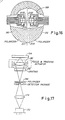
polarizer 208 of Figure 16 as a hologram lens. It is well known in the art that light diffraction efficiency is sensitive to the polarization of the incident light. Herwig Kogelnik discussed this effect in his paper "Coupled Wave Theory for Thick Hologram Gratings," published in The Bell System Technical Journal,volume 48, number 9, pp. 2909-2946, November 1969. A more recent work on a similar topic is a paper entitled "Grating Efficiency Theory as it Applies to Blazed and Holographic Grating" by E. G. Loewen, M. Neviere and D. Maystre, published in Applied Optics,volume 16,number 10, pp. 2711-2721, October 1977. This polarization effect becomes very strong when the grating period is less than the wavelength of light. - Figure 18 shows an arrangement for producing
polarizer 208 of Figure 16. Alaser source 216 preferably has a wavelength below 520nm. A laser with this wavelength is used to produce a polarizer for an optical head laser with a wavelength between 0.78 micrometers and 0.85 micrometers. The wavelength is selected so that a diffraction grating can be recorded on commercially available photoresist materials. With a.shorter wavelength the grating period formed on the diffraction grating can be made smaller than the near infrared wavelength of semiconductor lasers. - The laser beam from
laser source 216 is passed through acollimater 218 to produce acollimated beam 220 which passes through a beam-splitter 222 to produce a pair of collimatedbeams Beams mirrors recording material 232. Each of the expanded laser beams hits medium 232 at an angle e to a vector normal to the recording surface ofmedium 232. The interference pattern of the two intersecting laser beams will produce a series of lines which form the fringes of the hologram lens. The preferred process differs from the process discussed in the background section because no metal is deposited. Instead, the glass is etched to produce a relief pattern of a series of grooves on the glass. Since all portions of the hologram lens are thus transparent, its efficiency is much greater than a lens using a series of metal lines which block a portion of the light. - The distance between the lines, or the grating period, is d = 1/2 sin e, where a is the wavelength of a
laser source 216. For a laser source wavelength of 488nm and an angle 8 of 20°, the grating period will be approximately 0.71 micrometer. - Figure 19A shows the grating lines which can be formed by such a process. The parallel lines of Figure 19A are the fringes formed by the interference of the laser beams as shown in Figure 18. To manufacture a
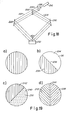
polarizer 208 as shown in Figure 16, a little more than one-half of the polarizer medium is covered by amask 234 as shown in Figure 19B. This mask is arranged so that itsboundary 236 is at a 45° angle to thefringes 238 which are produced by the interference pattern of the laser beams. After this first set offringes 238 are formed,mask 234 is removed and amask 240 is placed over thefringes 238 as shown in Figure 19C. This mask extends beyond thefringes 238 so that it covers more than half of the recording medium. The recording medium is rotated by 90° and a separate set offringes 242 are formed on the second half of the medium. The resultant polarizer is shown in Figure 19D as having a series offringes 238 on a first side which are orthogonal to a second set of -fringes 242 on a second side, with acentral portion 244 of the polarizer having no fringes at all. This central portion of the polarizer allows the passage of the source laser beam without polarization. - The relief pattern formed on photoresist on the recording medium can be replicated by an embossing process. This makes mass production of the - polarization elements possible at low cost for use in the thermal magnetic optical head according to the present invention. Such a phase diffraction grating has an advantage in terms of light diffraction efficiency over wire grid polarizers because the entire polarizer is transparent as discussed above.
- As will be understood by those familiar with the art, the present invention may be embodied in other specific forms without departing from the spirit or essential characteristics thereof. For example, a different pattern could be embodied on the hologram lens to produce an image for focus and tracking error detection. In the embodiment of Figure 15, the polarizer could be placed on the other side of
diffraction grating 178 orcollimating lens 180 anddiffraction grating 178 could be interchanged. Accordingly, the disclosure of the preferred embodiments of the invention is intended to be illustrative, but not limiting, of the scope of the invention which is set forth in the following claims.
Claims (14)
Applications Claiming Priority (4)
| Application Number | Priority Date | Filing Date | Title |
|---|---|---|---|
| US06/860,154 US4731772A (en) | 1986-05-06 | 1986-05-06 | Optical head using hologram lens for both beam splitting and focus error detection functions |
| US860154 | 1986-05-06 | ||
| US06/938,085 US4794585A (en) | 1986-05-06 | 1986-12-04 | Optical head having a hologram lens and polarizers for use with magneto-optic medium |
| US938085 | 1992-08-28 |
Publications (2)
| Publication Number | Publication Date |
|---|---|
| EP0244827A2 true EP0244827A2 (en) | 1987-11-11 |
| EP0244827A3 EP0244827A3 (en) | 1989-01-18 |
Family
ID=27127558
Family Applications (1)
| Application Number | Title | Priority Date | Filing Date |
|---|---|---|---|
| EP87106503A Withdrawn EP0244827A3 (en) | 1986-05-06 | 1987-05-05 | Improved optical head |
Country Status (4)
| Country | Link |
|---|---|
| US (1) | US4794585A (en) |
| EP (1) | EP0244827A3 (en) |
| KR (1) | KR910003043B1 (en) |
| DE (1) | DE244827T1 (en) |
Cited By (12)
| Publication number | Priority date | Publication date | Assignee | Title |
|---|---|---|---|---|
| EP0320276A2 (en) * | 1987-12-09 | 1989-06-14 | Sharp Kabushiki Kaisha | Optical pickup device |
| EP0325104A2 (en) * | 1988-01-20 | 1989-07-26 | Pencom International Corporation | Magneto-optical head with separate optical paths for error and data detection |
| EP0325103A2 (en) * | 1988-01-20 | 1989-07-26 | Pencom International Corporation | Method for constructing an optical head by varying a hologram pattern |
| EP0346907A2 (en) * | 1988-06-17 | 1989-12-20 | Pencom International Corporation | Tracking and focus actuator for a holographic optical head |
| EP0348950A2 (en) * | 1988-06-30 | 1990-01-03 | Pencom International Corporation | Hybrid surface emitting laser and detector |
| EP0365368A2 (en) * | 1988-10-21 | 1990-04-25 | Sharp Kabushiki Kaisha | An optical pickup device |
| EP0378438A2 (en) * | 1989-01-13 | 1990-07-18 | Sharp Kabushiki Kaisha | An optical pickup apparatus |
| WO1990011598A1 (en) * | 1989-03-17 | 1990-10-04 | Optical Recording Corporation | Optical recording and/or playback system with rotary scanner |
| EP0534373A2 (en) * | 1991-09-27 | 1993-03-31 | Sharp Kabushiki Kaisha | Optical pickup device |
| EP0608842A1 (en) * | 1993-01-25 | 1994-08-03 | Sony Corporation | Optical pick-up device |
| EP0634743A1 (en) * | 1993-07-15 | 1995-01-18 | GOLDSTAR CO. Ltd. | Optical pick-up device |
| EP0640962A1 (en) * | 1993-08-25 | 1995-03-01 | Sony Corporation | Optical device |
Families Citing this family (38)
| Publication number | Priority date | Publication date | Assignee | Title |
|---|---|---|---|---|
| DE3889509T2 (en) * | 1987-08-24 | 1994-10-20 | Sharp Kk | Optical scanning device and optical grating arrangement therefor. |
| JPH0770065B2 (en) * | 1988-04-20 | 1995-07-31 | シャープ株式会社 | Optical pickup device |
| US5062098A (en) * | 1988-10-19 | 1991-10-29 | Matsushita Electric Industrial Co., Ltd. | Optical pick-up device having holographic element |
| FR2642530A1 (en) * | 1989-01-30 | 1990-08-03 | Seiko Epson Corp | Focusing mechanism and optical head |
| US5050153A (en) * | 1989-06-06 | 1991-09-17 | Wai-Hon Lee | Semiconductor laser optical head assembly |
| CA2017229A1 (en) * | 1989-06-30 | 1990-12-31 | James A. Cox | Binary optical element for an optical disk read/write head |
| US5442433A (en) * | 1989-08-11 | 1995-08-15 | Nhk Spring Co., Ltd. | Identification system for an article having individually attached patches |
| US5200794A (en) * | 1989-08-11 | 1993-04-06 | Nhk Spring Co., Ltd. | Optical head for an optical authenticity identifing system |
| US5161133A (en) * | 1989-09-29 | 1992-11-03 | International Business Machines Corporation | Magneto-optical storage system |
| US5056881A (en) * | 1990-04-12 | 1991-10-15 | Amp Incorporated | Collimated laser diode |
| US5563868A (en) * | 1990-06-18 | 1996-10-08 | Matsushita-Kotobuki Electronics Industries, Ltd. | Optical servo system for magnetic disk |
| US5272550A (en) * | 1991-10-11 | 1993-12-21 | International Business Machines Corporation | Hologram system |
| US5673241A (en) * | 1991-11-08 | 1997-09-30 | Seiko Epson Corporation | Focus detection mechanism and optical head and optical storage device that use it |
| JPH07111726B2 (en) * | 1991-12-26 | 1995-11-29 | 日本発条株式会社 | Identification structure and identification object |
| KR930020374A (en) * | 1992-03-31 | 1993-10-19 | 정용문 | Optical pickup |
| JP2520346B2 (en) * | 1992-04-28 | 1996-07-31 | 日本発条株式会社 | Object identification structure |
| US5453961A (en) * | 1993-01-15 | 1995-09-26 | Eastman Kodak Company | Pick-up device for optical disk readout using waveguide gratings |
| US5517479A (en) * | 1993-03-26 | 1996-05-14 | Matsushita Electronics Corporation | Optical head including a semiconductor laser having a non-scatter incident area |
| JP3544239B2 (en) * | 1995-03-04 | 2004-07-21 | ソニー株式会社 | Optical pickup and optical recording medium reproducing apparatus |
| EP0740294A1 (en) * | 1995-04-26 | 1996-10-30 | Matsushita Electric Industrial Co., Ltd. | Optical head |
| US5789733A (en) * | 1996-09-20 | 1998-08-04 | Motorola, Inc. | Smart card with contactless optical interface |
| US7559460B2 (en) | 1996-11-15 | 2009-07-14 | Diebold Incorporated | Automated banking machine |
| US7513417B2 (en) | 1996-11-15 | 2009-04-07 | Diebold, Incorporated | Automated banking machine |
| US5923413A (en) * | 1996-11-15 | 1999-07-13 | Interbold | Universal bank note denominator and validator |
| US6573983B1 (en) | 1996-11-15 | 2003-06-03 | Diebold, Incorporated | Apparatus and method for processing bank notes and other documents in an automated banking machine |
| US7584883B2 (en) | 1996-11-15 | 2009-09-08 | Diebold, Incorporated | Check cashing automated banking machine |
| US6266473B1 (en) | 1997-02-07 | 2001-07-24 | Alliedsignal Inc. | Reflective display |
| JPH10333025A (en) * | 1997-05-28 | 1998-12-18 | Pioneer Electron Corp | Optical pickup device |
| US5991249A (en) * | 1997-07-29 | 1999-11-23 | Hoetron, Inc. | Optical track sensing device |
| JP2002124047A (en) * | 2000-10-11 | 2002-04-26 | Sony Corp | Magnetic disk device |
| US20020167727A1 (en) * | 2001-03-27 | 2002-11-14 | Hansen Douglas P. | Patterned wire grid polarizer and method of use |
| US6723980B2 (en) | 2001-07-16 | 2004-04-20 | Wai-Hon Lee | Position sensor with grating to detect moving object with periodic pattern |
| JP4285955B2 (en) * | 2001-09-07 | 2009-06-24 | 三洋電機株式会社 | Hologram optical element, misregistration detection device, and optical recording medium driving device |
| US6992765B2 (en) * | 2002-10-11 | 2006-01-31 | Intralase Corp. | Method and system for determining the alignment of a surface of a material in relation to a laser beam |
| EP1554720A2 (en) * | 2002-10-15 | 2005-07-20 | Koninklijke Philips Electronics N.V. | Optical scanning device |
| US20040090874A1 (en) * | 2002-11-08 | 2004-05-13 | Kunjithapatham Balasubramanian | Apparatus and method for effective reduction of a laser beam spot size |
| CN105628188B (en) * | 2016-01-11 | 2018-10-23 | 襄阳爱默思智能检测装备有限公司 | A kind of grating interference vibration measurement method |
| EP3345119A4 (en) * | 2016-01-29 | 2019-04-24 | Hewlett-Packard Development Company, L.P. | Optical readers |
Citations (6)
| Publication number | Priority date | Publication date | Assignee | Title |
|---|---|---|---|---|
| GB2059664A (en) * | 1979-09-25 | 1981-04-23 | Sony Corp | Optical reproducing heads |
| EP0147749A2 (en) * | 1983-12-16 | 1985-07-10 | Hitachi, Ltd. | Optical head |
| EP0219908A1 (en) * | 1985-10-17 | 1987-04-29 | Koninklijke Philips Electronics N.V. | Apparatus for optically scanning an information plane |
| EP0222238A2 (en) * | 1985-11-11 | 1987-05-20 | Sharp Kabushiki Kaisha | Pick-up device |
| EP0228620A2 (en) * | 1985-12-10 | 1987-07-15 | Nec Corporation | Optical head comprising a diffraction grating for directing two or more diffracted beams to optical detectors |
| EP0241372A1 (en) * | 1986-04-11 | 1987-10-14 | Thomson S.A. | Optical reading device for an optical-recording medium |
Family Cites Families (6)
| Publication number | Priority date | Publication date | Assignee | Title |
|---|---|---|---|---|
| FR2036613A5 (en) * | 1969-03-26 | 1970-12-24 | Jobin Et G Yvon | |
| FR2313716A1 (en) * | 1975-06-03 | 1976-12-31 | Thomson Brandt | OPTICAL READING SYSTEM BY REFLECTION OF AN INFORMATION MEDIA |
| JPS5953612B2 (en) * | 1975-11-19 | 1984-12-26 | カブシキガイシヤ フジテレビジヨン | Kodenshikisai Seihouhou |
| CA1091966A (en) * | 1976-10-15 | 1980-12-23 | Chiaki Kojima | Apparatus for reading signals recorded on a record carrier |
| US4241999A (en) * | 1978-08-24 | 1980-12-30 | Agence Nationale De Valorisation De La Recherche (Anvar) | Monochromators |
| JPS59119548A (en) * | 1982-12-25 | 1984-07-10 | Pioneer Electronic Corp | Optical pickup device |
-
1986
- 1986-12-04 US US06/938,085 patent/US4794585A/en not_active Expired - Lifetime
-
1987
- 1987-05-05 EP EP87106503A patent/EP0244827A3/en not_active Withdrawn
- 1987-05-05 DE DE198787106503T patent/DE244827T1/en active Pending
- 1987-05-06 KR KR1019870004421A patent/KR910003043B1/en active IP Right Grant
Patent Citations (6)
| Publication number | Priority date | Publication date | Assignee | Title |
|---|---|---|---|---|
| GB2059664A (en) * | 1979-09-25 | 1981-04-23 | Sony Corp | Optical reproducing heads |
| EP0147749A2 (en) * | 1983-12-16 | 1985-07-10 | Hitachi, Ltd. | Optical head |
| EP0219908A1 (en) * | 1985-10-17 | 1987-04-29 | Koninklijke Philips Electronics N.V. | Apparatus for optically scanning an information plane |
| EP0222238A2 (en) * | 1985-11-11 | 1987-05-20 | Sharp Kabushiki Kaisha | Pick-up device |
| EP0228620A2 (en) * | 1985-12-10 | 1987-07-15 | Nec Corporation | Optical head comprising a diffraction grating for directing two or more diffracted beams to optical detectors |
| EP0241372A1 (en) * | 1986-04-11 | 1987-10-14 | Thomson S.A. | Optical reading device for an optical-recording medium |
Non-Patent Citations (2)
| Title |
|---|
| PATENT ABSTRACTS OF JAPAN, vol. 8, no. 192 (P-298)[1629], 4th September 1984; & JP-A-59 79 446 (SHARP K.K.) 08-05-1984 * |
| TOPICAL MEETING ON OPTICAL DATA STORAGE, Stateline, Nevada, 11th-13th March 1987, pages 178-181; Y. KIMURA et al.: "A compact optical head using holographic optical element for CD players" * |
Cited By (22)
| Publication number | Priority date | Publication date | Assignee | Title |
|---|---|---|---|---|
| EP0320276A2 (en) * | 1987-12-09 | 1989-06-14 | Sharp Kabushiki Kaisha | Optical pickup device |
| EP0320276A3 (en) * | 1987-12-09 | 1990-06-06 | Sharp Kabushiki Kaisha | Optical pickup device optical pickup device |
| EP0325104A2 (en) * | 1988-01-20 | 1989-07-26 | Pencom International Corporation | Magneto-optical head with separate optical paths for error and data detection |
| EP0325103A2 (en) * | 1988-01-20 | 1989-07-26 | Pencom International Corporation | Method for constructing an optical head by varying a hologram pattern |
| EP0325103A3 (en) * | 1988-01-20 | 1991-08-28 | Pencom International Corporation | Method for constructing an optical head by varying a hologram pattern |
| EP0325104A3 (en) * | 1988-01-20 | 1991-06-12 | Pencom International Corporation | Magneto-optical head with separate optical paths for error and data detection |
| EP0346907A2 (en) * | 1988-06-17 | 1989-12-20 | Pencom International Corporation | Tracking and focus actuator for a holographic optical head |
| EP0346907A3 (en) * | 1988-06-17 | 1991-06-19 | Pencom International Corporation | Tracking and focus actuator for a holographic optical head |
| EP0348950A2 (en) * | 1988-06-30 | 1990-01-03 | Pencom International Corporation | Hybrid surface emitting laser and detector |
| EP0348950A3 (en) * | 1988-06-30 | 1990-07-04 | Pencom International Corporation | Hybrid surface emitting laser and detector |
| EP0365368A3 (en) * | 1988-10-21 | 1990-11-07 | Sharp Kabushiki Kaisha | An optical pickup device |
| EP0365368A2 (en) * | 1988-10-21 | 1990-04-25 | Sharp Kabushiki Kaisha | An optical pickup device |
| EP0378438A2 (en) * | 1989-01-13 | 1990-07-18 | Sharp Kabushiki Kaisha | An optical pickup apparatus |
| EP0378438A3 (en) * | 1989-01-13 | 1991-11-21 | Sharp Kabushiki Kaisha | An optical pickup apparatus |
| WO1990011598A1 (en) * | 1989-03-17 | 1990-10-04 | Optical Recording Corporation | Optical recording and/or playback system with rotary scanner |
| EP0534373A2 (en) * | 1991-09-27 | 1993-03-31 | Sharp Kabushiki Kaisha | Optical pickup device |
| EP0534373A3 (en) * | 1991-09-27 | 1993-06-09 | Sharp Kabushiki Kaisha | Optical pickup device |
| EP0608842A1 (en) * | 1993-01-25 | 1994-08-03 | Sony Corporation | Optical pick-up device |
| US5461224A (en) * | 1993-01-25 | 1995-10-24 | Sony Corporation | Optical pick-up device having light splitting means and focus error and tracking error detection |
| EP0634743A1 (en) * | 1993-07-15 | 1995-01-18 | GOLDSTAR CO. Ltd. | Optical pick-up device |
| EP0640962A1 (en) * | 1993-08-25 | 1995-03-01 | Sony Corporation | Optical device |
| US5679947A (en) * | 1993-08-25 | 1997-10-21 | Sony Corporation | Optical device having a light emitter and a photosensor on the same optical axis |
Also Published As
| Publication number | Publication date |
|---|---|
| EP0244827A3 (en) | 1989-01-18 |
| KR910003043B1 (en) | 1991-05-17 |
| DE244827T1 (en) | 1988-04-28 |
| KR870011588A (en) | 1987-12-24 |
| US4794585A (en) | 1988-12-27 |
Similar Documents
| Publication | Publication Date | Title |
|---|---|---|
| US4794585A (en) | Optical head having a hologram lens and polarizers for use with magneto-optic medium | |
| US4731772A (en) | Optical head using hologram lens for both beam splitting and focus error detection functions | |
| EP0268357B1 (en) | Optical system with grating lens assembly | |
| US5050153A (en) | Semiconductor laser optical head assembly | |
| US4918675A (en) | Magneto-optical head with separate optical paths for error and data detection | |
| KR100598645B1 (en) | Device for reading from or writing to an optical recording medium | |
| US4894815A (en) | Optical head for reading information from a magnetooptic recording medium | |
| US5684762A (en) | Opto-magnetic head apparatus | |
| EP0322714A2 (en) | Polarizing optical element and device using the same | |
| US6185176B1 (en) | Optical pickup apparatus | |
| US5243583A (en) | Optical pickup device with dual grating element | |
| JP2005339766A (en) | Optical disk apparatus | |
| USRE38648E1 (en) | Magneto-optical recording/reproducing pickup head with a diffraction grating and a wollaston prism | |
| US4987292A (en) | Method and apparatus for detecting focus and tracking errors | |
| US5182444A (en) | Split lens displaced long from each other along plane of cut | |
| JPH09180240A (en) | Optical head | |
| US5487058A (en) | Optical pick-up system with improved light-convergence construction | |
| JPS63241735A (en) | Optical pickup | |
| KR100448323B1 (en) | Optical information recording and reproducing apparatus | |
| CA1275731C (en) | Optical head having a hologram lens and polanzed for use with magnetic-opticmedium | |
| JP2618957B2 (en) | Polarizing optical element | |
| JP3558909B2 (en) | Optical pickup device | |
| JP3044667B2 (en) | Optical reader | |
| JP2685790B2 (en) | Device consisting of optical system including polarizing element | |
| JPH0457224A (en) | Optical head device |
Legal Events
| Date | Code | Title | Description |
|---|---|---|---|
| PUAI | Public reference made under article 153(3) epc to a published international application that has entered the european phase |
Free format text: ORIGINAL CODE: 0009012 |
|
| AK | Designated contracting states |
Kind code of ref document: A2 Designated state(s): DE FR GB IT NL |
|
| ITCL | It: translation for ep claims filed |
Representative=s name: UFFICIO TECNICO ING. A. MANNUCCI |
|
| TCNL | Nl: translation of patent claims filed | ||
| EL | Fr: translation of claims filed | ||
| DET | De: translation of patent claims | ||
| PUAL | Search report despatched |
Free format text: ORIGINAL CODE: 0009013 |
|
| AK | Designated contracting states |
Kind code of ref document: A3 Designated state(s): DE FR GB IT NL |
|
| 17P | Request for examination filed |
Effective date: 19890320 |
|
| 17Q | First examination report despatched |
Effective date: 19901022 |
|
| STAA | Information on the status of an ep patent application or granted ep patent |
Free format text: STATUS: THE APPLICATION IS DEEMED TO BE WITHDRAWN |
|
| 18D | Application deemed to be withdrawn |
Effective date: 19910302 |