EP0244854B1 - Wundklammerzange - Google Patents
Wundklammerzange Download PDFInfo
- Publication number
- EP0244854B1 EP0244854B1 EP87106590A EP87106590A EP0244854B1 EP 0244854 B1 EP0244854 B1 EP 0244854B1 EP 87106590 A EP87106590 A EP 87106590A EP 87106590 A EP87106590 A EP 87106590A EP 0244854 B1 EP0244854 B1 EP 0244854B1
- Authority
- EP
- European Patent Office
- Prior art keywords
- staple
- gun
- profiled
- magazine
- guide
- Prior art date
- Legal status (The legal status is an assumption and is not a legal conclusion. Google has not performed a legal analysis and makes no representation as to the accuracy of the status listed.)
- Expired - Lifetime
Links
Images

Classifications
-
- A—HUMAN NECESSITIES
- A61—MEDICAL OR VETERINARY SCIENCE; HYGIENE
- A61B—DIAGNOSIS; SURGERY; IDENTIFICATION
- A61B17/00—Surgical instruments, devices or methods, e.g. tourniquets
- A61B17/068—Surgical staplers, e.g. containing multiple staples or clamps
- A61B17/0682—Surgical staplers, e.g. containing multiple staples or clamps for applying U-shaped staples or clamps, e.g. without a forming anvil
- A61B17/0684—Surgical staplers, e.g. containing multiple staples or clamps for applying U-shaped staples or clamps, e.g. without a forming anvil having a forming anvil staying above the tissue during stapling
Definitions
- the invention relates to a wound clip pliers with a pliers main part, with a magazine held on the pliers main part, which two profile parts, which together form an elongated, cross-sectionally substantially U-shaped guide shaft for a supply of essentially U-shaped wound clips, one in the guide shaft Slidable slide and a slide feed spring to be prestressed on a clip discharge opening of the guide shaft, with stop means arranged in front of the clip discharge opening and limiting the clip ejection path, with a clip bending mechanism which has an anvil arranged in the region of the clip discharge opening of the magazine and one which is movable relative to the anvil Has pliers main part guided punch and with a pivotal handle part pivotally mounted on the pliers main part for actuating the clamp bending mechanism.
- Wound clip pliers of this type are known from EP-A-142 225. With this wound clamp pliers not only the bending punch but also the anvil is held on the main part of the pliers. The anvil forms the one in front of the staple delivery opening the magazine prevents the unwanted pushing out of the wound clips. The magazine is not interchangeable. The consequence of this is that the wound clamp forceps cannot be reloaded during the operation if the staple supply runs out. A complete second wound clamp forceps must be available, with the result that several complete wound clamp forceps must be sterilized after the operation. In addition, the known wound clip pliers are comparatively complex in terms of construction.
- WO 82/02486 discloses a wound clip pliers which, similar to the wound clip pliers explained above, comprises a main part of the forceps and a magazine held on the main part of the forceps.
- the magazine has two profile parts, which together form an elongated, generally U-shaped guide shaft in cross section for a supply of substantially U-shaped wound clips, and in the guide shaft a slide, which is biased by a clip feed spring onto a clip discharge opening of the guide slot, is arranged.
- the magazine has a front plate on which a bending mechanism designed as pliers is mounted in front of the Klarner discharge opening, which bends the wound clamp pressed against the front plate by the clip feed spring on its legs and bends it into a ring.
- a stop is arranged on the front plate of the magazine, which prevents the wound clip from escaping into the magazine during the bending process.
- the foremost wound clip in the bending mechanism is held in the magazine solely by friction.
- the two profile parts are guided together by a plug-in guide, which allows the profile parts to be assembled transversely to the longitudinal direction of the guide shaft.
- the two profile parts of the magazine have plug guides which run in the longitudinal direction of the guide shaft and fix the profile parts to one another on all sides, transversely to the guide shaft, in that the stop means limiting the staple extension path two on both sides of the staple discharge opening in front of the latter have stops arranged on the magazine that the anvil is arranged on the magazine and the staple discharge opening surrounds the anvil and that the magazine is releasably attached to the pliers main part together with the slide and the clamp feed spring.
- the stop which is preferably formed by two lugs or the like arranged on both sides of the clip ejection opening, prevents the clip feed spring from pushing the clip supply out of the magazine even when the magazine is removed. Since the profile parts can be inserted into one another in the longitudinal direction of the guide shaft, the magazine can be loaded with the wound clips without any problems, even if they are loose, i.e. wound clips that are not connected. The wound clips can be inserted into one of the two profile parts, and the other profile part can be pushed successively over the already inserted wound clips, thereby preventing the wound clips from falling out again when inserted.
- the magazine can be designed as a disposable magazine, the two profile parts expediently being permanently connected to one another, for example latched or glued, after the wound clips have been filled in.
- the magazine is also ideal for reloading. In particular, it can be easily and safely sterilized in the disassembled or at least partially opened state.
- a first of the two profile parts has an essentially U-shaped outer wall profile and closes the bottom of the magazine on the side facing away from the main part of the pliers.
- This first profile part is connected to the second profile part along its side walls projecting from the floor towards the second of the two profile parts via the plug-in guides.
- an elongated, in cross section substantially U-shaped clip guide part is inserted, from the bottom part of which side parts protrude toward the bottom of the first profile part.
- the staple guide part is adapted in its dimensions to the wound clips, which can be attached to this clip guide part with their legs towards the bottom of the first profile part.
- the bottom part of the clip guide part and the second profile part on the one hand, as well as the side parts of the clip guide part and the side walls of the first profile part on the other, are each at a distance from one another and delimit the guide shaft.
- the clip guide part and the bottom of the first profile part in turn delimit a spring chamber in which the clip feed spring, which is preferably designed as a helical compression spring, is accommodated in a space-saving manner.
- the slide has an extension which engages through a slot in the clip guide part into the spring chamber.
- the clamp guide part is preferably a bent sheet metal part which carries at its end adjacent to the clamp discharge opening a tab forming the anvil. At its other end, a support projection which extends above the height of the guide shaft and is supported on the second profile part is provided to absorb the tilting moments acting on the anvil. Spring claws or the like can be provided on the side cheeks of the bent sheet metal part for fastening the bent sheet metal part to the first profile part.
- the spring chamber is expediently accessible through an opening in an end wall of the first profile part, so that the clamp feed spring can also be installed or replaced after the sheet metal bent part has been installed.
- the clamp feed spring is supported on a closure piece which is inserted into a pocket which is open towards the second profile part after insertion of the clamp feed spring into the spring shaft in the pocket.
- the plug-in guides are expediently designed as groove-rib plug-in guides and preferably extend essentially over the entire length of the profile parts. Two pairs of grooves and ribs, which guide the two profile parts together in the manner of a dovetail guide, have proven particularly favorable.
- the guide surfaces of the grooves and ribs preferably taper towards the staple discharge opening and prevent the two profile parts from unintentionally separating from one another during use.
- the magazine can be locked to the main body of the pliers in a variety of ways.
- particularly simple replacement makes possible configurations in which one of the profile parts and the main pliers part have further plug-in guides which run essentially in the longitudinal direction of the guide shaft and which guide the one profile part on all sides of the main part of the pliers, fixed to the guide shaft.
- the magazine can be attached to the main part of the pliers along these plug-in guides. In contrast, the magazine is guided exactly in the direction of impact of the bending punch.
- a locking device consisting of a locking pawl on the main part of the pliers and a locking recess on the one profile part is particularly suitable, in particular if the locking pawl can be unlocked again by an actuating push button which is conveniently located on the main part of the pliers.
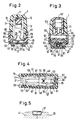
- the wound clamp pliers shown in FIGS. 1 to 4 comprise an essentially shell-shaped pliers main part 1, on which a pliers handle part 5 is pivotally mounted about an axis 3.
- the main tong part 1 has an essentially elongated shape and forms a handle 7 on one side of the axis 3, which is opposite a handle 9 of the tong handle part 5.
- the pliers main part 1 forms a chamber 11 in which a bending punch 13 is guided in a guide 15 displaceably transversely to the longitudinal direction of the pliers main part 1.
- the bending punch 13 carries a backdrop 17, in which a sliding block 19 engages at the free end of an arm 21 of the pliers handle part 5 opposite the handle 9.
- a magazine 25 is exchangeably fastened to the main pliers part 1.
- the magazine 25 encloses an elongated, in cross section essentially U-shaped guide shaft 27 (FIG. 3), in which a supply of loose, essentially U-shaped wound clips 29 is accommodated one behind the other in the longitudinal direction of the guide shaft 27.
- the Magazine carries an anvil 31, the width of which is smaller than the base length of the wound clips 29, so that the legs 33 of the wound clips protrude beyond the anvil 31 on both sides and of a bend recess 35 on the anvil-side end face of the anvil width, taking into account the thickness of the wound clips 29 Bending die 13 are bent into a wound clip ring 37 which clamps the wound halves 39, 41 together, as shown in FIG. 5.
- the magazine is interchangeably held on the main body 1 of the pliers. It comprises two elongated profile parts 43, 45 which enclose the guide shaft 27.
- the profile part 43 has a cross-sectionally substantially U-shaped outer wall profile with a bottom wall 47, from which two side walls 49 protrude toward the profile part 45.
- the longitudinal ribs 51 and longitudinal grooves 53 form plug-in guides, along which the profile part 43 is slidably guided on the profile part 45. These plug guides fix the two profile parts 43, 45 to one another transversely to the longitudinal direction.
- An essentially U-shaped clamp guide part 55 designed as a bent sheet metal part, is inserted into the profile part 43, the outside dimensions of which are adapted to the inside dimensions of the wound clips 29.
- the clamp guide part 55 together with a transverse wall 57 connecting the grooves 53 of the profile part 45 on the one hand and the side walls 49 of the profile part 43 on the other hand, delimits the guide shaft 27.
- Cheeks 61 are formed, from which, as best shown in FIG. 4, tongues 63 are punched out, which are clawed to the side walls 49 of the profile part 43 and hold the clamp guide part 55 on the profile part 43.
- the spring 69 is supported on a tab 71 of a slide 73, which rides longitudinally displaceably on the clamp guide part 55 in the guide shaft 27.
- the tab 71 engages through a longitudinal slot 75 of the clamp guide part 55 into the spring chamber 65.
- the spring 69 presses the wound clips 29 in the direction of a discharge opening 77 which surrounds the anvil 31 in a ring.
- lugs 79 projecting from the side walls 49 toward the anvil, which limit the extension path of the clips 29.
- the end of the profile part 43 opposite the anvil 31 is closed by an end wall 83 which contains an insertion opening 85 for the spring 69 which is aligned with the spring chamber 65.
- a plug 89 which can be inserted when the profile piece 45 is removed and on which the spring 69 is supported with its end facing away from the slide 73.
- the clip guide part 55 has, at its end facing away from the anvil 31, protrusion 91 projecting to the transverse wall 57 of the profile part 45, by means of which the clip guide part 55 is supported against tilting when the anvil 31 is subjected to pressure.
- the magazine 25 is assembled as follows:
- the clip guide part 55 is first inserted into the profile part 43 in the manner shown, whereby the tongues 63 claw in the side walls 49. Then the wound clips 29 are placed on the clip guide part 55, the profile part 45 being successively pushed onto the profile part 43 in order to prevent the clips already inserted from falling out and shifting.
- the slider 73 is put on and the profile part 45 is pushed close to the pocket 87 to fix the slider 73. Now the spring 69 is inserted through the insertion opening 85 and stretched with a tool, for example a screwdriver or the like, up to the pocket 87, whereupon the closure piece 89 is inserted into the pocket 87. Finally, the profile parts 43, 45 are pushed into one another.
- the guide surfaces of the longitudinal ribs 51 and the grooves 53 run towards one another, as indicated in FIGS.
- the profile part 45 holds the magazine 25 on the pliers main part 1.
- the profile part 45 On the side of the transverse wall 57 facing the pliers main part 1, the profile part 45 carries cheeks 93 which enclose the pliers main part 1 between them. Ribs 95, which extend in the longitudinal direction of the guide shaft 27 and which engage in complementary longitudinal grooves 97 of the cheeks 93, are provided on the main body 1 of the pliers. The profile part 45 and thus the magazine 25 can thus be plugged onto the main pliers part 1.
- the cheek 93 is adjacent to the staple discharge opening 77 by an end wall 99 which limits the insertion path of the magazine 25.
- a plate-shaped pawl 103 is slidably guided in grooves 101 of the chamber 11, which engages in an opening 105 of the transverse wall 57 and locks the magazine in the engaged state.
- the magazine 25 is pushed onto the longitudinal ribs 95 from the end of the pliers main part 1 facing away from the handle 7.
- the outer surface 121 of the transverse wall 57 facing the pawl 103 is designed in the form of an insertion bevel, by means of which the pawl 103 automatically snaps into the opening 105.
- the push button 117 is pressed, with which the magazine can be pulled off freely.
- the main pliers part 1, the pliers handle part 5, the lever 109 and the profile parts 43 and 45 consist of injection-molded, sterilizable plastic.
- the shaped profile part 43 expediently consists of a transparent plastic material in order to be able to recognize from the outside how many wound clips the magazine still contains.
- the bending punch 13, the guide profile part 55 and the pawl 103 are preferably made of stainless steel.
Description
- Die Erfindung betrifft eine Wundklammerzange mit einem Zangenhauptteil, mit einem an dem Zangenhauptteil gehaltenen Magazin, welches zwei Profilteile, die gemeinsam einen langgestreckten, im Querschnitt im wesentlichen U-förmigen Führungsschacht für einen Vorrat von im wesentlichen U-förmigen Wundklammern bilden, einen in dem Führungsschacht verschiebbaren Schieber sowie eine den Schieber auf eine Klammerabgabeöffnung des Führungsschachts zu vorspannende Klammervorschubfeder aufweist, mit vor der Klammerabgabeöffnung angeordneten, den Klammerausschubweg begrenzenden Anschlagmitteln, mit einem Klammerbiegemechanismus, welcher einen im Bereich der Klammerabgabeöffnung des Magazins angeordneten Amboß und einen relativ zu dem Amboß beweglich an dem Zangenhauptteil geführten Biegestempel aufweist und mit einem schwenkbar an dem Zangenhauptteil gelagerten Zangengriffteil zur Betätigung des Klammerbiegemechanismus.
- Eine Wundklammerzange dieser Art ist aus der EP-A-142 225 bekannt. Bei dieser Wundklammerzange ist nicht nur der Biegestempel sondern auch der Amboß an dem Zangenhauptteil gehalten. Der Amboß bildet den vor der Klammerabgabeöffnung des Magazins das ungewollte Ausschieben der Wundklammern verhindernden Anschlag. Das Magazin ist nicht auswechselbar. Dies hat zur Folge, daß die Wundklammerzange während der Operation nicht nachgeladen werden kann, falls der Klammervorrat zu Ende gehen sollte. Es muß eine vollständige zweite Wundklammerzange zur Verfügung stehen, mit der Folge, daß nach der Operation mehrere vollständige Wundklammerzangen sterilisiert werden müssen. Darüberhinaus ist die bekannte Wundklammerzange konstruktiv vergleichsweise aufwendig.
- Aus WO 82/02486 ist eine Wundklammerzange bekannt, die ähnlich der vorstehend erläuterten Wundklammerzange ein Zangenhauptteil und ein an dem Zangenhauptteil gehaltenes Magazin umfaßt. Das Magazin hat zwei Profilteile, die gemeinsam einen langgestreckten, im Querschnitt im wesentlichen U-förmigen Führungsschacht für einen Vorrat von im wesentlichen U-förmigen Wundklammern bilden, und in dem Führungsschacht ist ein von einer Klammervorschubfeder auf eine Klammerabgabeöffnung des Führungsschachts vorgespannter Schieber angeordnet. Das Magazin hat eine Frontplatte, an der vor der Klarnerabgabeöffnung ein als Zange ausgebildeter Biegemechanismus gelagert ist, der die von der Klammervorschubfeder gegen die Frontplatte gedrückte Wundklammer an ihren Schenkeln erfaßt und zu einem Ring biegt. An der Frontplatte des Magazins ist ein Anschlag angeordnet, der verhindert, daß die Wundklammer während des Biegevorgangs in das Magazin hinein ausweicht. Die in dem Biegemechanismus liegende, jeweils vorderste Wundklammer wird ausschließlich durch Reibung in dem Magazin gehalten. Die beiden Profilteile sind durch eine Steckführung aneinander geführt, die das Zusammensetzen der Profilteile quer zur Längsrichtung des Führungsschachts erlaubt.
- Es ist ferner bekannt, Wundklammerzangen in Einwegversion herzustellen, die nach Gebrauch weggeworfen werden. Da derartige Wundklammerzangen, obwohl sie für Einwegbenutzung konzipiert sind, vergleichsweise aufwendig sind, ist diese Lösung vergleichsweise teuer.
- Es ist Aufgabe der Erfindung, eine konstruktiv einfache Wundklammerzange anzugeben, bei welcher das Magazin betriebsmäßig auswechselbar sein soll, so daß die Wundklammerzange auch während der Operation mit einem neuen Vorrat an Wundklammern nachgeladen werden kann. Darüberhinaus soll sichergestellt sein, daß das Magazin auf einfachste Weise mit den Wundklammern geladen werden kann.
- Diese Aufgabe wird ausgehend von der eingangs erläuterten Wundklammerzange erfindungsgemäß dadurch gelöst, daß die beiden Profilteile des Magazins in Längsrichtung des Führungsschachts verlaufende Steckführungen aufweisen, die die Profilteile quer zum Führungsschacht aneinander allseitig fixiert führen, daß die den Klammerausschubweg begrenzenden Anschlagmittel zwei beiderseits der Klammerabgabeöffnung vor dieser an dem Magazin angeordnete Anschläge aufweisen, daß auch der Amboß an dem Magazin angeordnete ist und die Klammerabgabeöffnung den Amboß umgibt und daß das Magazin zusammen mit dem Schieber und der Klammervorschubfeder als Einheit lösbar an dem Zangen hauptteil befestigt ist.
- Für die Operation können mehrere mit Wundklammern gefüllte Magazine bereitgehalten werden, die nacheinander an dem Zangenhauptteil der Wundklammerzange befestigt werden. Der vorzugsweise durch zwei beiderseits der Klammerausschuböffnung angeordnete Nasen oder dergleichen gebildete Anschlag verhindert auch bei abgenommenem Magazin, daß die Klammervorschubfeder den Klammervorrat aus dem Magazin ausschiebt. Da die Profilteile in Längsrichtung des Führungsschachts ineinander steckbar sind, läßt sich das Magazin problemlos mit den Wundklammern laden, selbst wenn es sich um lose, d.h. nicht miteinander verbundene Wundklammern handelt. Die Wundklammern können in eines der beiden Profilteile eingelegt werden, und das andere Profilteil kann sukzessive über die bereits eingelegten Wundklammern geschoben werden, wodurch verhindert wird, daß die Wundklammern beim Einlegen wieder herausfallen.
- Das Magazin kann als Einwegmagazin ausgebildet sein, wobei zweckmäßigerweise die beiden Profilteile nach dem Einfüllen der Wundklammern dauerhaft miteinander verbunden, beispielsweise verrastet oder verklebt werden. Das Magazin eignet sich jedoch auch vorzüglich zum Nachladen. Insbesondere kann es in zerlegtem oder zumindest teilweise geöffnetem Zustand leicht und sicher sterilisiert werden.
- In einer bevorzugten Ausgestaltung hat ein erstes der beiden Profilteile ein im wesentlichen U-förmiges Außenwandprofil und verschließt mit seinem Boden das Magazin auf der dem Zangenhauptteil abgewandten Seite. Dieses erste Profilteil ist entlang seiner vom Boden weg zum zweiten der beiden Profilteile hin vorstehenden Seitenwände über die Steckführungen mit dem zweiten Profilteil verbunden. In das erste Profilteil ist ein langgestrecktes, im Querschnitt im wesentlichen U-förmiges Klammerführungsteil eingesetzt, von dessen Bodenteil Seitenteile zum Boden des ersten Profilteils hin abstehen. Das Klammerführungsteil ist in seinen Abmessungen den Wundklammern angepaßt, die mit ihren Schenklen zum Boden des ersten Profilteils hin auf dieses Klammerführungsteil aufgesteckt werden können. Der Bodenteil des Klammerführungsteils und das zweite Profilteil einerseits sowie die Seitenteile des Klammerführungsteils und die Seitenwände des ersten Profilteils andererseits liegen sich jeweils mit Abstand voneinander gegenüber und begrenzen den Führungsschacht. Das Klammerführungsteil und der Boden des ersten Profilteils begrenzen ihrerseits eine Federkammer, in welcher die vorzugsweise als Schraubendruckfeder ausgebildete Klammervorschubfeder platzsparend untergebracht ist. Der Schieber hat in dieser Ausgestaltung einen Ansatz, der durch einen Schlitz des Klammerführungsteils hindurch in die Federkammer eingreift.
- Bei dem Klammerführungsteil handelt es sich bevorzugt um ein Blechbiegeteil, welches an seinem der Klammerabgabeöffnung benachbarten Ende einen den Amboß bildenden Lappen trägt. An seinem anderen Ende ist zur Aufnahme der auf den Amboß wirkenden Kippmomente ein über die Höhe des Führungsschachts reichender Abstützvorsprung vorgesehen, der sich an dem zweiten Profilteil abstützt. Zur Befestigung des Blechbiegeteils an dem ersten Profilteil können an Seitenwangen des Blechbiegeteils Federkrallen oder dergleichen vorgesehen sein.
- Die Federkammer ist zweckmäßigerweise durch eine Öffnung in einer Stirnwand des ersten Profilteils zugänglich, so daß die Klammervorschubfeder auch nach dem Einbau des Blechbiegeteils eingebaut oder ausgewechselt werden kann. Die Klammervorschubfeder stützt sich an einem Verschlußstück ab, welches in eine zum zweiten Profilteil hin offene Tasche nach dem Einführen der Klammervorschubfeder in den Federschacht in die Tasche eingesteckt wird.
- Die Steckführungen sind zweckmäßigerweise als Nut-Rippen-Steckführungen ausgebildet und erstrecken sich vorzugsweise im wesentlichen über die gesamte Länge der Profilteile. Als besonders günstig haben sich zwei Paare von Nuten und Rippen erwiesen, die nach Art einer Schwalbenschwanzführung die beiden Profilteile aneinander führen. Die Führungsflächen der Nuten und Rippen verjüngen sich bevorzugt zur Klammerabgabeöffnung hin und verhindern im Klemmsitz, daß sich die beiden Profilteile beim Gebrauch unbeabsichtigt voneinander lösen.
- Die Verrastung des Magazins an dem Zangenhauptteil kann auf vielfältige Weise erfolgen. Betriebsmäßig besonders einfaches Auswechseln ermöglichen Ausgestaltungen, bei welchen eines der Profilteile und das Zangenhauptteil weitere, im wesentlichen in Längsrichtung der Führungsschachts verlaufende Steckführungen aufweisen, die das eine Profilteil quer zum Führungsschacht allseitig fixiert an dem Zangenhauptteil führen. Das Magazin kann längs dieser Steckführungen auf das Zangenhauptteil aufgesteckt werden. In Auftreffrichtung des Biegestempels hingegen wird das Magazin exakt geführt. Zur Fixierung in Richtung der Steckführungen eignet sich insbesondere eine aus einer Rastklinke am Zangenhauptteil und einer Rastaussparung an dem einen Profilteil bestehende Verriegelungsvorrichtung, insbesondere dann, wenn die Rastklinke durch einen griffgünstig am Zangenhauptteil angeordneten Betätigungs-Druckknopf wieder entriegelt werden kann.
- Im folgenden soll ein Ausführungsbeispiel der Erfindung anhand von Zeichnungen näher erläutert werden. Es zeigt:
- Fig. 1
- einen Längsschnitt durch eine Wundklammerzange;
- Fig. 2
- einen Querschnitt durch die Wundklammerzange entlang einer Linie II-II in Fig. 1;
- Fig. 3
- einen Querschnitt durch die Wundklammerzange gesehen entlang einer Linie III-III in Fig. 1;
- Fig. 4
- einen Querschnitt durch das Magazin der Wundklammerzange, gesehen entlang einer Linie IV-IV in Fig. 1 und
- Fig. 5
- eine schematische Darstellung einer mit der Wundklammerzange der Fig. 1 gebogenen Wundklammer.
- Die in den Fig. 1 bis 4 dargestellte Wundklammerzange umfaßt ein im wesentlichen schalenförmiges Zangenhauptteil 1, an welchem um eine Achse 3 schwenkbar ein Zangengriffteil 5 gelagert ist. Das Zangenhauptteil 1 hat im wesentlichen langgestreckte Form und bildet auf einer Seite der Achse 3 einen Handgriff 7, dem ein Handgriff 9 des Zangengriffteils 5 gegenüberliegt. Auf der dem Handgriff 7 gegenüberliegenden Seiten der Achse 3 bildet das Zangenhauptteil 1 eine Kammer 11, in der quer zur Längsrichtung des Zangenhauptteils 1 ein Biegestempel 13 in einer Führung 15 verschiebbar geführt ist. Der Biegestempel 13 trägt eine Kulisse 17, in die ein Kulissenstein 19 am freien Ende eines dem Handgriff 9 gegenüberliegenden Arms 21 des Zangengriffteils 5 eingreift. Eine zwischen den Handgriffen 7 und 9 geführt eingespannte Schraubendruckfeder 23 hält den Biegestempel 13 in seiner in die Kammer 11 eingezogenen Stellung, aus der er durch Zusammendrücken der Handgriffe 7, 9 ausgeschoben werden kann.
- Dem Ausschubende des Biegestemptels 13 gegenüberliegend ist an dem Zangenhauptteil 1 ein Magazin 25 auswechselbar befestigt. Das Magazin 25 umschließt einen langgestreckten, im Querschnitt im wesentlichen U-förmigen Führungsschacht 27 (Fig. 3), in welchem ein Vorrat loser, im wesentlichen U-förmiger Wundklammern 29 in Längsrichtung des Führungsschachts 27 hintereinander untergebracht ist. Das Magazin trägt einen Amboß 31, dessen Breite kleiner ist als die Basislänge der Wundklammern 29, so daß die Schenkel 33 der Wundklammern beiderseits über den Amboß 31 vorstehen und von einer der Amboßbreite unter Berücksichtigung der Dicke der Wundklammern 29 angepaßten Biegeaussparung 35 an der amboßseitigen Stirnseite des Biegestempels 13 zu einem Wundklammerring 37 gebogen werden, der die Wundhälften 39, 41 zusammenklammert, wie dies in Fig. 5 dargestellt ist.
- Das Magazin ist als Einheit auswechselbar an dem Zangenhauptteil 1 gehalten. Es umfaßt zwei langgestreckte Profilteile 43, 45, die den Führungsschacht 27 umschließen. Das Profilteil 43 hat ein im Querschnitt im wesentlichen U-förmiges Außenwandprofil mit einer Bodenwand 47, von der zwei Seitenwände 49 zum Profilteil 45 hin abstehen. An den freien Längsrändern der Seitenwände 49 sind in Längsrichtung des Führungskanals 27 verlaufende, voneinander weg abstehende Längsrippen 51 vorgesehen, die nach Art einer Schwalbenschwanzführung in komplementäre, am anderen Profilteil 45 vorgesehene Längsnuten 53 eingreifen. Die Längsrippen 51 und Längsnuten 53 bilden Steckführungen, längs der das Profilteil 43 an dem Profilteil 45 verschiebbar geführt ist. Quer zur Längsrichtung fixieren diese Steckführungen die beiden Profilteile 43, 45 aneinander.
- In das Profilteil 43 ist ein im wesentlichen U-förmiges, als Blechbiegeteil ausgebildetes Klammerführungsteil 55 eingesetzt, dessen Außenabmessungen den Innenabmessungen der Wundklammern 29 angepaßt ist. Das Klammerführungsteil 55 begrenzt zusammen mit einer die Nuten 53 verbindenden Querwand 57 des Profilteils 45 einerseits und den Seitenwänden 49 des Profilteils 43 andererseits den Führungsschacht 27. An den freien Längsrändern der Seitenteile 59 des Klammerführungsteils 55 sind voneinander weg abstehende Wangen 61 angeformt, aus welchen, wie am besten Fig. 4 zeigt, Zungen 63 freigestanzt sind, die mit den Seitenwänden 49 des Profilteils 43 verkrallt sind und das Klammerführungsteil 55 an dem Profilteil 43 halten.
- Der vom Inneren des Klammerführungsteils 55 und der Bodenwand 47 umschlossene Bereich bildet eine Federkammer 65, in welcher durch Rippen 67 geführt eine längs des Führungsschachts 27 wirkende Schraubendruckfeder 69 angeordnet ist. Die Feder 69 stützt sich an einem Lappen 71 eines Schiebers 73 ab, der in dem Führungsschacht 27 längsverschiebbar auf dem Klammerführungsteil 55 reitet. Der Lappen 71 greift durch einen Längsschlitz 75 des Klammerführungsteils 55 hindurch in die Federkammer 65.
- Die Feder 69 drückt die Wundklammern 29 in Richtung einer den Amboß 31 ringförmig umgebenden Abgabeöffnung 77. Vor der Abgabeöffnung 77 sind von den Seitenwänden 49 zum Amboß hin vorstehende Nasen 79 angeordnet, die den Ausschubweg der Klammern 29 begrenzen.
- Das dem Amboß 31 gegenüberliegende Ende des Profilteils 43 ist durch eine Stirnwand 83 verschlossen, welche eine mit der Federkammer 65 fluchtende Einführöffnung 85 für die Feder 69 enthält. In einer Tasche 87 der Stirnwand 83 sitzt ein bei abgenommenem Profilstück 45 einsteckbares Verschlußstück 89, an welchem sich die Feder 69 mit ihrem dem Schieber 73 abgewandten Ende abstützt. Das Klammerführungsteil 55 hat an seinem dem Amboß 31 abgewandten Ende zur Querwand 57 des Profilteils 45 vorstehende Anprägung 91, über die sich das Klammerführungsteil 55 bei der Druckbelastung des Ambosses 31 kippsicher abstützt. Das Magazin 25 wird wie folgt zusammengebaut:
- Das Klammerführungsteil 55 wird zunächst in der dargestellten Weise in das Profilteil 43 eingesetzt, wobei sich die Zungen 63 in den Seitenwänden 49 verkrallen. Dann werden die Wundklammern 29 auf das klammerführungsteil 55 aufgelegt, wobei sukzessive das Profilteil 45 auf das Profilteil 43 aufgesteckt wird, um das Herausfallen und Verschieben der bereits eingelegten Klammern zu verhindern. Es wird der Schieber 73 aufgesetzt und das Profilteil 45 zur Fixierung des Schiebers 73 bis nahe an die Tasche 87 herangeschoben. Jetzt wird die Feder 69 durch die Einführöffnung 85 eingeführt und mit einem Werkzeug, beispielsweise einem Schraubenzieher oder dergleichen bis vor die Tasche 87 gespannt, worauf das Verschlußstück 89 in die Tasche 87 eingesetzt wird. Abschließend werden die Profilteile 43, 45 fertig ineinandergeschoben. Die Führungsflächen der Längsrippen 51 und der Nuten 53 verlaufen, wie in den Fig. 2 bis 4 angedeutet ist, aufeinander zu, so daß das Profilteil 43 im Klemmsitz zur Abgabeöffnung 77 hin fixiert ist.
- Das Profilteil 45 hält das Magazin 25 an dem Zangenhauptteil 1. Auf der zum Zangenhauptteil 1 weisenden Seite der Querwand 57 trägt das Profilteil 45 Wangen 93, die das Zangenhauptteil 1 zwischen sich einschließen. An dem Zangenhauptteil 1 sind in Längsrichtung des Führungsschachts 27 verlaufende Rippen 95 vorgesehen, die in komplementäre Längsnuten 97 der Wangen 93 eingreifen. Das Profilteil 45 und damit das Magazin 25 läßt sich somit auf das Zangenhauptteil 1 aufstecken. Der Klammerabgabeöffnung 77 benachbart sind die Wangen 93 durch eine Stirnwand 99 miteinander verbunden, die den Einschubweg des Magazins 25 begrenzt.
- Zur Verriegelung des Magazins 25 an den Zangenhauptteil 1 ist in Nuten 101 der Kammer 11 eine plattenförmige Klinke 103 verschiebbar geführt, die in eine Öffnung 105 der Querwand 57 eingreift und im Eingriffszustand das Magazin verrastet. Ein an einer Achse 107 schwenkbar an dem Zangenhauptteil 1 gelagerter, doppelarmiger Bedienungshebel 109 greift mit seinem einen Arm 111 in die Klinke 103 und trägt an seinem anderen Arm 113 einen durch eine Öffnung 115 auf der dem Magazin 25 abgewandten Seite des Zangenhauptteils 1 austretenden Betätigungs-Druckknopf 117. Eine zwischen dem Arm 113 und dem Handgriff 9 des Zangengriffteils 5 geführt eingespannte Schraubendruckfeder 119 spannt die Klinke 103 in Verriegelungsrichtung vor und unterstützt, da sie wirkungsmäßig der Feder 23 parallel geschaltet ist, die Öffnungsbewegung der Zange, so daß die Feder 23 schwächer dimensioniert sein kann.
- Das Magazin 25 wird von der dem Handgriff 7 abgewandten Ende des Zangenhauptteils 1 auf die Längsrippen 95 aufgesteckt. Die der Klinke 103 zugewandte Außenfläche 121 der Querwand 57 ist in Form einer Einführschräge ausgebildet, über die die Klinke 103 in die Öffnuing 105 selbttätig einschnappt. Zum Lösen des Magazins 25 wird der Druckknopf 117 gedrückt, womit das Magazin frei abgezogen werden kann.
- Das Zangenhauptteil 1, das Zangengriffteil 5, der Hebel 109 sowie die Profilteile 43 und 45 bestehen aus spritzgußgeformtem, sterilisierbarem Kunststoff. Zweckmäßigerweise besteht das Profilformteil 43 aus einem transparenten Kunststoffmaterial, um von außen her erkennen zu können, wieviele Wundklammern das Magazin noch enthält. Der Biegestempel 13, das Führungsprofilteil 55 und die Klinke 103 sind vorzugsweise aus nichtrostendem Stahl gefertigt.
Claims (11)
- Wundklammerzange,
mit einem Zangenhauptteil (1),
mit einem an dem Zangenhauptteil (1) gehaltenen Magazin (25), welches zwei Profilteile (43, 45), die gemeinsam einen langgestreckten, im Querschnitt im wesentlichen U-förmigen Führungsschacht (27) für einen Vorrat von im wesentlichen U-förmigen Wundklammern (29) bilden, einen in dem Führungsschacht (27) verschiebbaren Schieber (73) sowie eine den Schieber (73) auf eine Klammerabgabeöffnung (77) des Führungsschachts (27) zu vorspannende Klammervorschubfeder (69) aufweist,
mit vor der Klammerabgabeöffnung (77) angeordneten, den Klammerausschubweg begrenzenden Anschlagmitteln (79), mit einem Klammerbiegemechanismus, welcher einen im Bereich der Klammerabgabeöffnung (77) des Magazins (25) angeordneten Amboß (31) und einen relativ zu dem Amboß (31) beweglich an dem Zangenhauptteil (1) geführten Biegestempel (13) aufweist
und mit einem schwenkbar an dem Zangenhauptteil (1) gelagerten Zangengriffteil (5) zur Betätigung des Klammerbiegemechanismus,
dadurch gekennzeichnet, daß die beiden Profilteile (43, 45) des Magazins (25) in Längsrichtung des Führungsschachts (27) verlaufende Steckführungen (51, 53) aufweisen, die die Profilteile (43, 45) quer zum Führungsschacht (27) aneinander allseitig fixiert führen,
daß die den Klammerausschubweg begrenzenden Anschlagmittel zwei beiderseits der Klammerabgabeöffnung (77) vor dieser an dem Magazin (25) angeordnete Anschläge (79) aufweisen, daß auch der Amboß (31) an dem Magazin (25) angeordnet ist und die Klammerabgabeöffnung (77) den Amboß (31) umbigt und daß das Magazin (25) zusammen mit dem Schieber (73) und der Klammervorschubfeder (69) als Einheit lösbar an dem Zangenhauptteil (1) befestigt ist. - Wundklammerzange nach Anspruch 1, dadurch gekennzeichnet, daß ein erstes (43) der Profilteile ein im wesentlichen U-förmiges Außenwandprofil hat und mit seinem Boden (47) das Magazin (25) auf der dem Zangenhauptteil (1) abgewandten Seite verschließt sowie entlang seiner vom Boden (47) weg zum zweiten (45) der Profilteile vorstehenden Seitenwände (49) über die Steckführungen (51, 53) mit dem zweiten Profilteil (45) verbunden ist, daß in das erste Profilteil (43) ein langgestrecktes, im Querschnitt im wesentlichen U-förmiges Klammerführungsteil (55) eingesetzt ist, von dessen Bodenteil Seitenteile (59) zum Boden (47) des ersten Profilteils (43) abstehen, wobei sich der Bodenteil und das zweite Profilteil (43) einerseits sowie die Seitenteile (59) und die Seitenwände (49) des ersten Profilteils (43) andererseits jeweils mit Abstand voneinander gegenüberliegen und den Führungsschacht (27) begrenzen,
daß die Klammervorschubfeder (69) in einer durch das Klammerführungsteil (55) und den Boden (47) des ersten Profilteils (43) begrenzten Federkammer (65) angeordnet ist
und daß das Klammerführungsteil (55) einen in Längsrichtung verlaufenden Schlitz (75) aufweist, durch den hindurch ein Ansatz (71) des Schiebers (73) in die Federkammer (65) eingreift. - Wundklammerzange nach Anspruch 2, dadurch gekennzeichnet, daß das Klammerführungsteil (55) als Blechbiegeteil ausgebildet ist und an seinem der Klammerabgabeöffnung (77) benachbarten Ende einen den Amboß (31) bildenden Lappen und an seinem anderen Ende einen zum zweiten Profilteil (45) vorspringenden Abstützvorsprung (91) trägt.
- Wundklammerzange nach Anspruch 3, dadurch gekennzeichnet, daß die dem Bodenteil abgewandten Längsränder der Seitenteile (59) des Klammerführungsteils (55) an den Seitenwänden (49) des ersten Profilteils (43) abgestützte Seitenwangen (61) haben, aus welchen Federkrallen (63) freigestanzt sind.
- Wundklammerzange nach einem der Ansprüche 2 bis 4, dadurch gekennzeichnet, daß das der Klammerabgabeöffnung (77) abgewandte Ende des Führungsschachts (27) durch eine Stirnwand (83) des ersten Profilteils (43) verschlossen ist, daß die Stirnwand (83) eine Öffnung (85) zum Einführen der Klammervorschubfeder (69) in die Federkammer (65) aufweist und daß im Bereich der Stirnwand (83) eine zum zweiten Profilteil (45) hin offene Tasche (87) zum Einstecken eines die Einführöffnung (85) verschließenden Verschlußstücks (89) vorgesehen ist, an dem sich die Klammervorschubfeder (69) abstützt.
- Wundklammerzange nach einem der Ansprüche 1 bis 5, dadurch gekennzeichnet, daß die Steckführungen (51, 53) als im wesentlichen über die gesamte Länge eines (45) der Profilteile sich erstreckende Nuten (53) ausgebildet sind, denen in Längsrichtung sich erstreckende Rippen (51) des anderen Profilteils (43) zugeordnet sind.
- Wundklammerzange nach Anspruch 6, dadurch gekennzeichnet, daß zwei zueinander entgegengerichtet vorspringende Paare von Nuten (53) und Rippen (51) vorgesehen sind, deren Führungsflächen in Längsrichtung zur Klammerabgabeöffnung hin aufeinander zu verlaufen.
- Wundklammerzange nach einem der Ansprüche 1 bis 7, dadurch gekennzeichnet, daß eines der Profilteile (45) und das Zangenhauptteil (1) weitere, im wesentlichen in Längsrichtung des Führungsschachts (27) verlaufende Steckführungen (95, 97) aufweisen, die das eine Profilteil (45) quer zum Führungsschacht (27) allseitig fixiert an dem Zangenhauptteil (1) führen.
- Wundklammerzange nach Anspruch 8, dadurch gekennzeichnet, daß in dem einen Profilteil (45) eine Rastaussparung (105) und an dem Zangenhauptteil (1) eine Rastklinke (103) beweglich geführt ist, die von einer Rastfeder (119) in Richtung des Eingriffs in die Rastaussparung (105) vorgespannt ist.
- Wundklammerzange nach Anspruch 9, dadurch gekennzeichnet, daß in dem Zangenhauptteil (1) parallelachsig zum Zangengriffteil (5) ein doppelarmiger Hebel (109) gelagert ist, der mit seinem einen Arm (111) mit der Rastklinke (103) verbunden ist und dessen anderer Arm (113) einen durch eine Öffnung (115) des Zangenhauptteils (1) austretenden Betätigungs-Druckknopf (117) bildet.
- Wundklammerzange nach Anspruch 10, dadurch gekennzeichnet, daß die Rastfeder (119) zwischen dem anderen Arm (113) und dem Zangengriffteil (5) eingespannt ist und das Zangengriffteil (5) in Zangenöffnungsrichtung belastet.
Priority Applications (1)
| Application Number | Priority Date | Filing Date | Title |
|---|---|---|---|
| AT87106590T ATE91867T1 (de) | 1986-05-07 | 1987-05-07 | Wundklammerzange. |
Applications Claiming Priority (2)
| Application Number | Priority Date | Filing Date | Title |
|---|---|---|---|
| DE3615405A DE3615405C2 (de) | 1986-05-07 | 1986-05-07 | Wundklammerzange |
| DE3615405 | 1986-05-07 |
Publications (3)
| Publication Number | Publication Date |
|---|---|
| EP0244854A2 EP0244854A2 (de) | 1987-11-11 |
| EP0244854A3 EP0244854A3 (en) | 1988-12-21 |
| EP0244854B1 true EP0244854B1 (de) | 1993-07-28 |
Family
ID=6300318
Family Applications (1)
| Application Number | Title | Priority Date | Filing Date |
|---|---|---|---|
| EP87106590A Expired - Lifetime EP0244854B1 (de) | 1986-05-07 | 1987-05-07 | Wundklammerzange |
Country Status (6)
| Country | Link |
|---|---|
| US (1) | US4813586A (de) |
| EP (1) | EP0244854B1 (de) |
| JP (1) | JPS6323652A (de) |
| AT (1) | ATE91867T1 (de) |
| DE (2) | DE3615405C2 (de) |
| ES (1) | ES2043618T3 (de) |
Families Citing this family (40)
| Publication number | Priority date | Publication date | Assignee | Title |
|---|---|---|---|---|
| DE3934698A1 (de) * | 1989-10-18 | 1991-04-25 | Beiersdorf Ag | Chirurgisches geraet zum setzen von wundklammern |
| DE4027474C2 (de) * | 1990-08-30 | 1999-09-02 | Diener | Wundklammerzange |
| DE4108952A1 (de) * | 1991-03-19 | 1992-09-24 | Beiersdorf Ag | Geraet zum setzen von wundklammern |
| US5258010A (en) * | 1991-05-30 | 1993-11-02 | United States Surgical Corporation | Anvilless surgical apparatus for applying surgical fasteners |
| DE4303544A1 (en) * | 1992-02-07 | 1993-09-23 | Storz Karl Gmbh & Co | Surgical instrument for applying clips to surgical incision - has reloading magazine which holds clips in sterile environment |
| DE4421695A1 (de) * | 1994-06-21 | 1996-01-04 | Pierre Nicolas Dr Med Foss | Verfahren zur Ligation oberflächlicher Gefässe |
| US9579091B2 (en) | 2000-01-05 | 2017-02-28 | Integrated Vascular Systems, Inc. | Closure system and methods of use |
| US6461364B1 (en) | 2000-01-05 | 2002-10-08 | Integrated Vascular Systems, Inc. | Vascular sheath with bioabsorbable puncture site closure apparatus and methods of use |
| US6942674B2 (en) | 2000-01-05 | 2005-09-13 | Integrated Vascular Systems, Inc. | Apparatus and methods for delivering a closure device |
| US7842068B2 (en) | 2000-12-07 | 2010-11-30 | Integrated Vascular Systems, Inc. | Apparatus and methods for providing tactile feedback while delivering a closure device |
| US6391048B1 (en) | 2000-01-05 | 2002-05-21 | Integrated Vascular Systems, Inc. | Integrated vascular device with puncture site closure component and sealant and methods of use |
| EP1372489B1 (de) | 2000-04-11 | 2011-01-05 | United States Surgical Corporation | Vorrichtung zum reparieren des meniskus in einer einzigen operation |
| AU8800801A (en) * | 2000-09-08 | 2002-03-22 | James E Coleman | Surgical staple |
| US6626918B1 (en) | 2000-10-06 | 2003-09-30 | Medical Technology Group | Apparatus and methods for positioning a vascular sheath |
| US6695867B2 (en) * | 2002-02-21 | 2004-02-24 | Integrated Vascular Systems, Inc. | Plunger apparatus and methods for delivering a closure device |
| US6623510B2 (en) | 2000-12-07 | 2003-09-23 | Integrated Vascular Systems, Inc. | Closure device and methods for making and using them |
| US7211101B2 (en) * | 2000-12-07 | 2007-05-01 | Abbott Vascular Devices | Methods for manufacturing a clip and clip |
| US7905900B2 (en) * | 2003-01-30 | 2011-03-15 | Integrated Vascular Systems, Inc. | Clip applier and methods of use |
| US8690910B2 (en) | 2000-12-07 | 2014-04-08 | Integrated Vascular Systems, Inc. | Closure device and methods for making and using them |
| US7806904B2 (en) * | 2000-12-07 | 2010-10-05 | Integrated Vascular Systems, Inc. | Closure device |
| IES20010547A2 (en) * | 2001-06-07 | 2002-12-11 | Christy Cummins | Surgical Staple |
| US7850709B2 (en) * | 2002-06-04 | 2010-12-14 | Abbott Vascular Inc. | Blood vessel closure clip and delivery device |
| US7416556B2 (en) * | 2002-06-06 | 2008-08-26 | Abbott Laboratories | Stop-cock suture clamping system |
| US20030229377A1 (en) * | 2002-06-10 | 2003-12-11 | Thomas Tong | Tube and rod suture clamping system |
| US7108710B2 (en) * | 2002-11-26 | 2006-09-19 | Abbott Laboratories | Multi-element biased suture clip |
| US8398656B2 (en) | 2003-01-30 | 2013-03-19 | Integrated Vascular Systems, Inc. | Clip applier and methods of use |
| US7857828B2 (en) * | 2003-01-30 | 2010-12-28 | Integrated Vascular Systems, Inc. | Clip applier and methods of use |
| US8905937B2 (en) | 2009-02-26 | 2014-12-09 | Integrated Vascular Systems, Inc. | Methods and apparatus for locating a surface of a body lumen |
| SE0301441D0 (sv) * | 2003-05-16 | 2003-05-16 | Astrazeneca Ab | Diarylmethylidene piperidine derivatives, preparations thereof and uses thereof |
| IES20040368A2 (en) | 2004-05-25 | 2005-11-30 | James E Coleman | Surgical stapler |
| JP2006305136A (ja) * | 2005-04-28 | 2006-11-09 | Manii Kk | 医療用ステープラー |
| US8926633B2 (en) | 2005-06-24 | 2015-01-06 | Abbott Laboratories | Apparatus and method for delivering a closure element |
| US8313497B2 (en) | 2005-07-01 | 2012-11-20 | Abbott Laboratories | Clip applier and methods of use |
| USD611144S1 (en) | 2006-06-28 | 2010-03-02 | Abbott Laboratories | Apparatus for delivering a closure element |
| US7954687B2 (en) * | 2007-11-06 | 2011-06-07 | Tyco Healthcare Group Lp | Coated surgical staples and an illuminated staple cartridge for a surgical stapling instrument |
| US8893947B2 (en) | 2007-12-17 | 2014-11-25 | Abbott Laboratories | Clip applier and methods of use |
| US7841502B2 (en) | 2007-12-18 | 2010-11-30 | Abbott Laboratories | Modular clip applier |
| US9486191B2 (en) | 2009-01-09 | 2016-11-08 | Abbott Vascular, Inc. | Closure devices |
| JP5628542B2 (ja) * | 2010-03-31 | 2014-11-19 | マニー株式会社 | 医療用ステープラー |
| US9364209B2 (en) | 2012-12-21 | 2016-06-14 | Abbott Cardiovascular Systems, Inc. | Articulating suturing device |
Family Cites Families (8)
| Publication number | Priority date | Publication date | Assignee | Title |
|---|---|---|---|---|
| US4179057A (en) * | 1978-11-17 | 1979-12-18 | Senco Products, Inc. | Disposable surgical stapling instrument |
| AU540655B2 (en) * | 1980-05-14 | 1984-11-29 | United States Surgical Corporation | Surgical stapler |
| US4406392A (en) * | 1980-05-27 | 1983-09-27 | American Cyanamid Company | Surgical stapling instrument |
| US4591086A (en) * | 1980-09-26 | 1986-05-27 | American Cyanamid Company | Surgical stapling instrument |
| US4375866A (en) * | 1981-01-22 | 1983-03-08 | Edward Weck & Company, Inc. | Skin clip applier |
| US4410125A (en) * | 1981-10-02 | 1983-10-18 | United States Surgical Corporation | Surgical stapler apparatus with curved staple pusher |
| US4491133A (en) * | 1982-02-05 | 1985-01-01 | Ethicon, Inc. | Folding cartridge for a multiple clip applier |
| US4582237A (en) * | 1983-08-26 | 1986-04-15 | Anthony Storace | Surgical stapling system, apparatus and staple |
-
1986
- 1986-05-07 DE DE3615405A patent/DE3615405C2/de not_active Expired - Fee Related
-
1987
- 1987-04-24 US US07/042,320 patent/US4813586A/en not_active Expired - Fee Related
- 1987-05-07 DE DE8787106590T patent/DE3786697D1/de not_active Expired - Fee Related
- 1987-05-07 EP EP87106590A patent/EP0244854B1/de not_active Expired - Lifetime
- 1987-05-07 JP JP62109940A patent/JPS6323652A/ja active Pending
- 1987-05-07 AT AT87106590T patent/ATE91867T1/de not_active IP Right Cessation
- 1987-05-07 ES ES87106590T patent/ES2043618T3/es not_active Expired - Lifetime
Also Published As
| Publication number | Publication date |
|---|---|
| ATE91867T1 (de) | 1993-08-15 |
| DE3786697D1 (de) | 1993-09-02 |
| US4813586A (en) | 1989-03-21 |
| EP0244854A2 (de) | 1987-11-11 |
| EP0244854A3 (en) | 1988-12-21 |
| ES2043618T3 (es) | 1994-01-01 |
| DE3615405C2 (de) | 1995-06-22 |
| JPS6323652A (ja) | 1988-01-30 |
| DE3615405A1 (de) | 1987-11-12 |
Similar Documents
| Publication | Publication Date | Title |
|---|---|---|
| EP0244854B1 (de) | Wundklammerzange | |
| DE3249116C2 (de) | Chirurgisches Instrument | |
| DE2845213C3 (de) | Vorrichtung zum Setzen chirurgischer Klammern | |
| DE3323671C2 (de) | Ligaturinstrument zum Applizieren von Klammern auf Blutgefäße o.dgl. | |
| DE3590364C2 (de) | Instrument zum Anbringen von chirurgischen Klemmen | |
| DE3347519C2 (de) | Heftwerkzeug | |
| DE3390238C2 (de) | Instrument zum Anbringen einer chirurgischen Klammer an K¦rpergewebe | |
| DE19752331C1 (de) | Magazin für ein chirurgisches Clipanlegegerät | |
| DE19752332C1 (de) | Clipanlegegerät | |
| DE2739809C3 (de) | Chirurgisches Werkzeug zum Formen und Implantieren einer Klammer | |
| DE3029083C2 (de) | Chirurgisches Instrument zum Applizieren von Gefäßklemmen | |
| DE3490450C2 (de) | Instrument zum Einsetzen von chirurgischen Befestigungselementen | |
| DE102009018820A1 (de) | Magazin mit einer Vielzahl C-förmiger Ligaturklammern | |
| DE2743900A1 (de) | Breite faszienklammer und patrone dafuer | |
| DE1791114B1 (de) | Chirurgisches Geraet zum Klammernaehen von Geweben | |
| DE202008014110U1 (de) | Abisolierzange | |
| DE2309396B2 (de) | Vorrichtung für Einsatzschraubenschlüssel zur lösbaren axialen Befestigung eines Steckschlüssels | |
| DE19537299A1 (de) | Klammerapplikator | |
| DE3038565C2 (de) | Heftapparat | |
| DE2926386C2 (de) | Heftgerät, insbesondere Schreibtischhefter | |
| DE102012112882B4 (de) | Stechhilfe zur Gewinnung von Körperflüssigkeitsproben | |
| DE819542C (de) | Heftgeraet, insbesondere Taschengeraet | |
| DE2618074A1 (de) | Magazinhalterung | |
| DE102007000838A1 (de) | Auspressvorrichtung | |
| EP1537953B1 (de) | Magaziniervorrichtung |
Legal Events
| Date | Code | Title | Description |
|---|---|---|---|
| PUAI | Public reference made under article 153(3) epc to a published international application that has entered the european phase |
Free format text: ORIGINAL CODE: 0009012 |
|
| 17P | Request for examination filed |
Effective date: 19870507 |
|
| AK | Designated contracting states |
Kind code of ref document: A2 Designated state(s): AT BE CH DE ES FR GB GR IT LI LU NL SE |
|
| PUAL | Search report despatched |
Free format text: ORIGINAL CODE: 0009013 |
|
| AK | Designated contracting states |
Kind code of ref document: A3 Designated state(s): AT BE CH DE ES FR GB GR IT LI LU NL SE |
|
| 17Q | First examination report despatched |
Effective date: 19920319 |
|
| GRAA | (expected) grant |
Free format text: ORIGINAL CODE: 0009210 |
|
| AK | Designated contracting states |
Kind code of ref document: B1 Designated state(s): AT BE CH DE ES FR GB GR IT LI LU NL SE |
|
| PG25 | Lapsed in a contracting state [announced via postgrant information from national office to epo] |
Ref country code: SE Effective date: 19930728 Ref country code: NL Effective date: 19930728 Ref country code: GR Free format text: LAPSE BECAUSE OF FAILURE TO SUBMIT A TRANSLATION OF THE DESCRIPTION OR TO PAY THE FEE WITHIN THE PRESCRIBED TIME-LIMIT Effective date: 19930728 |
|
| REF | Corresponds to: |
Ref document number: 91867 Country of ref document: AT Date of ref document: 19930815 Kind code of ref document: T |
|
| ITF | It: translation for a ep patent filed |
Owner name: JACOBACCI CASETTA & PERANI S.P.A. |
|
| GBT | Gb: translation of ep patent filed (gb section 77(6)(a)/1977) |
Effective date: 19930727 |
|
| REF | Corresponds to: |
Ref document number: 3786697 Country of ref document: DE Date of ref document: 19930902 |
|
| ET | Fr: translation filed | ||
| REG | Reference to a national code |
Ref country code: ES Ref legal event code: FG2A Ref document number: 2043618 Country of ref document: ES Kind code of ref document: T3 |
|
| NLV1 | Nl: lapsed or annulled due to failure to fulfill the requirements of art. 29p and 29m of the patents act | ||
| PG25 | Lapsed in a contracting state [announced via postgrant information from national office to epo] |
Ref country code: LU Free format text: LAPSE BECAUSE OF NON-PAYMENT OF DUE FEES Effective date: 19940531 |
|
| PLBE | No opposition filed within time limit |
Free format text: ORIGINAL CODE: 0009261 |
|
| STAA | Information on the status of an ep patent application or granted ep patent |
Free format text: STATUS: NO OPPOSITION FILED WITHIN TIME LIMIT |
|
| 26N | No opposition filed | ||
| PGFP | Annual fee paid to national office [announced via postgrant information from national office to epo] |
Ref country code: FR Payment date: 19950418 Year of fee payment: 9 |
|
| PGFP | Annual fee paid to national office [announced via postgrant information from national office to epo] |
Ref country code: GB Payment date: 19950419 Year of fee payment: 9 |
|
| PGFP | Annual fee paid to national office [announced via postgrant information from national office to epo] |
Ref country code: CH Payment date: 19950421 Year of fee payment: 9 |
|
| PGFP | Annual fee paid to national office [announced via postgrant information from national office to epo] |
Ref country code: BE Payment date: 19950510 Year of fee payment: 9 |
|
| PGFP | Annual fee paid to national office [announced via postgrant information from national office to epo] |
Ref country code: ES Payment date: 19950516 Year of fee payment: 9 |
|
| PGFP | Annual fee paid to national office [announced via postgrant information from national office to epo] |
Ref country code: AT Payment date: 19950531 Year of fee payment: 9 |
|
| PG25 | Lapsed in a contracting state [announced via postgrant information from national office to epo] |
Ref country code: GB Effective date: 19960507 Ref country code: AT Effective date: 19960507 |
|
| PG25 | Lapsed in a contracting state [announced via postgrant information from national office to epo] |
Ref country code: ES Free format text: LAPSE BECAUSE OF NON-PAYMENT OF DUE FEES Effective date: 19960508 |
|
| PG25 | Lapsed in a contracting state [announced via postgrant information from national office to epo] |
Ref country code: LI Effective date: 19960531 Ref country code: CH Effective date: 19960531 Ref country code: BE Effective date: 19960531 |
|
| BERE | Be: lapsed |
Owner name: DIENER HELMUT Effective date: 19960531 |
|
| GBPC | Gb: european patent ceased through non-payment of renewal fee |
Effective date: 19960507 |
|
| REG | Reference to a national code |
Ref country code: CH Ref legal event code: PL |
|
| PG25 | Lapsed in a contracting state [announced via postgrant information from national office to epo] |
Ref country code: FR Effective date: 19970131 |
|
| REG | Reference to a national code |
Ref country code: FR Ref legal event code: ST |
|
| REG | Reference to a national code |
Ref country code: ES Ref legal event code: FD2A Effective date: 19990201 |
|
| PGFP | Annual fee paid to national office [announced via postgrant information from national office to epo] |
Ref country code: DE Payment date: 19990531 Year of fee payment: 13 |
|
| PG25 | Lapsed in a contracting state [announced via postgrant information from national office to epo] |
Ref country code: DE Free format text: LAPSE BECAUSE OF NON-PAYMENT OF DUE FEES Effective date: 20010301 |
|
| PG25 | Lapsed in a contracting state [announced via postgrant information from national office to epo] |
Ref country code: IT Free format text: LAPSE BECAUSE OF NON-PAYMENT OF DUE FEES;WARNING: LAPSES OF ITALIAN PATENTS WITH EFFECTIVE DATE BEFORE 2007 MAY HAVE OCCURRED AT ANY TIME BEFORE 2007. THE CORRECT EFFECTIVE DATE MAY BE DIFFERENT FROM THE ONE RECORDED. Effective date: 20050507 |