EP0245584A1 - Röntgenuntersuchungsgerät mit einer ein Röntgensystem tragenden Säule - Google Patents
Röntgenuntersuchungsgerät mit einer ein Röntgensystem tragenden Säule Download PDFInfo
- Publication number
- EP0245584A1 EP0245584A1 EP87101523A EP87101523A EP0245584A1 EP 0245584 A1 EP0245584 A1 EP 0245584A1 EP 87101523 A EP87101523 A EP 87101523A EP 87101523 A EP87101523 A EP 87101523A EP 0245584 A1 EP0245584 A1 EP 0245584A1
- Authority
- EP
- European Patent Office
- Prior art keywords
- column
- ray
- carriage
- ray system
- examination apparatus
- Prior art date
- Legal status (The legal status is an assumption and is not a legal conclusion. Google has not performed a legal analysis and makes no representation as to the accuracy of the status listed.)
- Granted
Links
Images
Classifications
-
- F—MECHANICAL ENGINEERING; LIGHTING; HEATING; WEAPONS; BLASTING
- F16—ENGINEERING ELEMENTS AND UNITS; GENERAL MEASURES FOR PRODUCING AND MAINTAINING EFFECTIVE FUNCTIONING OF MACHINES OR INSTALLATIONS; THERMAL INSULATION IN GENERAL
- F16C—SHAFTS; FLEXIBLE SHAFTS; ELEMENTS OR CRANKSHAFT MECHANISMS; ROTARY BODIES OTHER THAN GEARING ELEMENTS; BEARINGS
- F16C29/00—Bearings for parts moving only linearly
- F16C29/04—Ball or roller bearings
- F16C29/045—Ball or roller bearings having rolling elements journaled in one of the moving parts
-
- A—HUMAN NECESSITIES
- A61—MEDICAL OR VETERINARY SCIENCE; HYGIENE
- A61B—DIAGNOSIS; SURGERY; IDENTIFICATION
- A61B6/00—Apparatus for radiation diagnosis, e.g. combined with radiation therapy equipment
- A61B6/44—Constructional features of apparatus for radiation diagnosis
- A61B6/4429—Constructional features of apparatus for radiation diagnosis related to the mounting of source units and detector units
- A61B6/4435—Constructional features of apparatus for radiation diagnosis related to the mounting of source units and detector units the source unit and the detector unit being coupled by a rigid structure
- A61B6/4441—Constructional features of apparatus for radiation diagnosis related to the mounting of source units and detector units the source unit and the detector unit being coupled by a rigid structure the rigid structure being a C-arm or U-arm
-
- F—MECHANICAL ENGINEERING; LIGHTING; HEATING; WEAPONS; BLASTING
- F16—ENGINEERING ELEMENTS AND UNITS; GENERAL MEASURES FOR PRODUCING AND MAINTAINING EFFECTIVE FUNCTIONING OF MACHINES OR INSTALLATIONS; THERMAL INSULATION IN GENERAL
- F16C—SHAFTS; FLEXIBLE SHAFTS; ELEMENTS OR CRANKSHAFT MECHANISMS; ROTARY BODIES OTHER THAN GEARING ELEMENTS; BEARINGS
- F16C29/00—Bearings for parts moving only linearly
- F16C29/005—Guide rails or tracks for a linear bearing, i.e. adapted for movement of a carriage or bearing body there along
-
- F—MECHANICAL ENGINEERING; LIGHTING; HEATING; WEAPONS; BLASTING
- F16—ENGINEERING ELEMENTS AND UNITS; GENERAL MEASURES FOR PRODUCING AND MAINTAINING EFFECTIVE FUNCTIONING OF MACHINES OR INSTALLATIONS; THERMAL INSULATION IN GENERAL
- F16C—SHAFTS; FLEXIBLE SHAFTS; ELEMENTS OR CRANKSHAFT MECHANISMS; ROTARY BODIES OTHER THAN GEARING ELEMENTS; BEARINGS
- F16C29/00—Bearings for parts moving only linearly
- F16C29/04—Ball or roller bearings
- F16C29/048—Ball or roller bearings with thin walled races, e.g. tracks of sheet metal
-
- F—MECHANICAL ENGINEERING; LIGHTING; HEATING; WEAPONS; BLASTING
- F16—ENGINEERING ELEMENTS AND UNITS; GENERAL MEASURES FOR PRODUCING AND MAINTAINING EFFECTIVE FUNCTIONING OF MACHINES OR INSTALLATIONS; THERMAL INSULATION IN GENERAL
- F16C—SHAFTS; FLEXIBLE SHAFTS; ELEMENTS OR CRANKSHAFT MECHANISMS; ROTARY BODIES OTHER THAN GEARING ELEMENTS; BEARINGS
- F16C2300/00—Application independent of particular apparatuses
- F16C2300/10—Application independent of particular apparatuses related to size
- F16C2300/14—Large applications, e.g. bearings having an inner diameter exceeding 500 mm
-
- F—MECHANICAL ENGINEERING; LIGHTING; HEATING; WEAPONS; BLASTING
- F16—ENGINEERING ELEMENTS AND UNITS; GENERAL MEASURES FOR PRODUCING AND MAINTAINING EFFECTIVE FUNCTIONING OF MACHINES OR INSTALLATIONS; THERMAL INSULATION IN GENERAL
- F16C—SHAFTS; FLEXIBLE SHAFTS; ELEMENTS OR CRANKSHAFT MECHANISMS; ROTARY BODIES OTHER THAN GEARING ELEMENTS; BEARINGS
- F16C2316/00—Apparatus in health or amusement
- F16C2316/10—Apparatus in health or amusement in medical appliances, e.g. in diagnosis, dentistry, instruments, prostheses, medical imaging appliances
Definitions
- the invention relates to an X-ray examination device with a column carrying an X-ray system, which can be moved in parallel rails on the floor and on the ceiling of the examination room.
- a C-arm with an X-ray emitter and a radiation receiver at its ends can be provided as the X-ray system.
- a device of this type can be used for angiocardiography and interventional technology.
- the area of the patient to be examined is selected by adjusting the C-arm along its circumferential direction, by pivoting the C-arm and by moving the column.
- the invention has for its object to provide an X-ray examination device of the type mentioned in such a way that the X-ray system is longitudinally displaceable in a simple manner on the column.
- the column is a closed box profile and on two parallel longitudinal sides opposite each other has a U-shaped, longitudinally extending recess, the recesses serving as rails for a longitudinally displaceable carriage on the column, the X-ray system wearing.
- a carriage carrying the X-ray system can be adjusted in the longitudinal direction on the column, special rails not being provided for this carriage.
- the Rails are formed by the column itself, which is designed as a hollow profile, specifically from its walls.
- the column can expediently be made of light metal in the extrusion process.
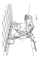
- a C-arm 1 is shown in FIG. 1, which carries at its ends an X-ray emitter 2 and an X-ray image intensifier 3 with a subsequent single-image camera 4 and a television camera that is not visible.
- the C-arm 1 is adjustably mounted along its circumference on a holder 5 which is connected to a carriage 7 so as to be pivotable about a horizontal axis 6.
- the carriage 7 is mounted in a longitudinally displaceable manner on a vertical column 8, which runs in a ceiling rail 9 and a floor rail 10, which run parallel to one another and to the longitudinal direction of a patient support table 11 which is displaceable. This C-arm 1 grips the patient positioning table 11 transversely.
- the patient support table 11 is mounted on a base 14 so that it can be adjusted in height, to which a control panel 15 is attached. It is adjustable relative to the base 14 in the longitudinal and transverse directions (floating storage), but the travel in the longitudinal direction is relatively small (order of magnitude 40 cm).
- the area examined is selected essentially by adjusting the X-ray emitter 2 and the X-ray image intensifier 3, that is to say not by adjustment of the patient table 11.
- the setting can be made in the following way:
- the column 8 is moved completely to the left by motor. In the position reached in this way, the C-arm 1 is brought into the respective examination position (image intensifier 3 above or below the patient positioning table 11 or to the side thereof). The column 8 is then retracted until the x-ray emitter 2 and the x-ray image intensifier 3 lie below or above the area of the patient to be irradiated or to the side thereof. The respective altitude of the isocenter is set via the carriage 7. Finally, the beam direction can also be varied by pivoting the C-arm 1 about the axis 6.
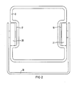
- FIG. 2 shows that the column 8 consists of a closed box section which, on two parallel longitudinal sides, has a U-shaped recess 17, 18 extending in the longitudinal direction opposite each other.
- the depressions 17, 18 serve as rails for the carriage 7.
- a bow-shaped part 19 is shown, on which wheels 20, 21 are rotatably mounted, which roll in the depressions 17, 18 in the longitudinal direction of the column 8.
Abstract
Description
- Die Erfindung betrifft ein Röntgenuntersuchungsgerät mit einer ein Röntgensystem tragenden Säule, die in parallelen Schienen am Fußboden und an der Decke des Untersuchungsraumes verschiebbar ist.
- Bei einem Röntgenuntersuchungsgerät dieser Art kann als Röntgensystem ein C-Bogen mit einem Röntgenstrahler und einem Strahlenempfänger an seinen Enden vorgesehen sein Ein Gerät dieser Art kann für die Angiokardiographie und die interventionelle Technik verwendet werden. Der zu untersuchende Bereich des Patienten wird dabei durch Einstellung des C-Bogens längs seiner Umfangsrichtung, durch Verschwenken des C-Bogens und durch Verfahren der Säule gewählt.
- Der Erfindung liegt die Aufgabe zugrunde, ein Röntgenuntersuchungsgerät der eingangs genannten Art so auszubilden, daß das Röntgensystem in einfacher Weise auf der Säule längsverschiebbar ist.
- Diese Aufgabe ist erfindungsgemäß dadurch gelöst, daß die Säule ein geschlossenes Kastenprofil ist und an zwei parallelen Längsseiten einander gegenüberliegend je eine U-förmige, in Längsrichtung verlaufende Vertiefung aufweist, wobei die Vertiefungen als Schienen für einen auf der Säule längsverschiebbaren Wagen dienen, der das Röntgensystem trägt. Bei dem erfindungsgemäßen Röntgenuntersuchungsgerät ist ein das Röntgensystem tragender Wagen auf der Säule in Längsrichtung einstellbar, wobei besondere Schienen für diesen Wagen nicht vorgesehen sind. Die Schienen sind von der als Hohlprofil ausgebildeten Säule selbst, und zwar von deren Wandungen gebildet. Die Säule kann dabei zweckmäßigerweise aus Leichtmetall im Strangpreßverfahren hergestellt werden.
- Die Erfindung ist nachfolgend anhand eines in der Zeichnung dargestellten Ausführungsbeispieles näher erläutert.
Es zeigen: - Fig. 1 ein Röntgenuntersuchungsgerät nach der Erfindung, und
- Fig. 2 eine Einzelheit des Röntgenuntersuchungsgerätes gemäß Figur 1.
- In der Figur 1 ist ein C-Bogen 1 dargestellt, der an seinen Enden einen Röntgenstrahler 2 und einen Röntgenbildverstärker 3 mit nachgeschalteter Einzelbildkamera 4 sowie nicht sichtbarer Fernsehkamera trägt. Der C-Bogen 1 ist längs seines Umfanges an einem Halter 5 verstellbar gelagert, welcher um eine horizontale Achse 6 schwenkbar mit einem Wagen 7 verbunden ist. Der Wagen 7 ist an einer vertikalen Säule 8 längsverschiebbar gelagert, welche in einer Deckenschiene 9 und einer Bodenschiene 10, welche parallel zueinander und zur Längsrichtung eines Patientenlagerungstisches 11 verlaufen, der verschiebbar ist. Dieser C-Bogen 1 umgreift den Patientenlagerungstisch 11 quer. Der Patientenlagerungstisch 11 ist auf einem Sockel 14 höhenverstellbar gelagert, an dem ein Bedienpult 15 befestigt ist. Er ist gegenüber dem Sockel 14 in Längs- und Querrichtung verstellbar (schwimmende Lagerung), wobei jedoch der Stellweg in Längsrichtung relativ klein ist (Größenordnung 40 cm).
- Die Wahl des untersuchten Bereiches erfolgt im wesentlichen durch Einstellung des Röntgenstrahlers 2 und des Röntgenbildverstärkers 3, also nicht durch Verstellung des Patientenlagerungstisches 11. Die Einstellung kann dabei in folgender Weise erfolgen:
- Zunächst wird die Säule 8 motorisch ganz nach links verfahren. In der so erreichten Stellung wird der C-Bogen 1 in die jeweilige Untersuchungslage gebracht (Bildverstärker 3 oberhalb oder unterhalb des Patientenlagerungstisches 11 oder seitlich von diesem). Anschließend wird die Säule 8 so weit zurückgefahren, bis der Röntgenstrahler 2 und der Röntgenbildverstärker 3 unter bzw. über dem zu durchstrahlenden Bereich des Patienten oder seitlich von diesem liegen. Die jeweilige Höhenlage des Isozentrums wird dabei über den Wagen 7 eingestellt. Schließlich kann die Strahlenrichtung auch noch durch Schwenken des C-Bogens 1 um die Achse 6 variiert werden.
- Die Figur 2 zeigt, daß die Säule 8 aus einem geschlossenen Kastenprofil besteht, das an zwei parallelen Längsseiten einander gegenüberliegend je eine U-förmige, in Längsrichtung verlaufende Vertiefung 17, 18 aufweist. Die Vertiefungen 17, 18 dienen als Schienen für den Wagen 7. Vom Wagen 7 ist ein bügelförmiger Teil 19 dargestellt, an dem Räder 20, 21 drehbar gelagert sind, die in den Vertiefungen 17, 18 in Längsrichtung der Säule 8 abrollen.
Claims (1)
- Röntgenuntersuchungsgerät mit einer ein Röntgensystem (2, 3, 4) tragenden Säule (8), auf der ein Wagen (7) längsverschiebbar gelagert ist, der das Röntgensystem (2, 3, 4) trägt, dadurch gekennzeichnet, daß die Säule (8) ein geschlossenes Kastenprofil ist und an zwei parallelen Längsseiten einander gegenüberliegend je eine U-förmige, in Längsrichtung verlaufende Vertiefung (17, 18) aufweist, wobei die Vertiefungen (17, 18) als Schienen für einen auf der Säule (8) längsverschiebbaren Wagen (7) dienen, der das Röntgensystem (2, 3, 4) trägt.
Applications Claiming Priority (2)
| Application Number | Priority Date | Filing Date | Title |
|---|---|---|---|
| DE8612867U | 1986-05-12 | ||
| DE8612867U DE8612867U1 (de) | 1986-05-12 | 1986-05-12 |
Publications (2)
| Publication Number | Publication Date |
|---|---|
| EP0245584A1 true EP0245584A1 (de) | 1987-11-19 |
| EP0245584B1 EP0245584B1 (de) | 1990-05-23 |
Family
ID=6794535
Family Applications (1)
| Application Number | Title | Priority Date | Filing Date |
|---|---|---|---|
| EP87101523A Expired - Lifetime EP0245584B1 (de) | 1986-05-12 | 1987-02-05 | Röntgenuntersuchungsgerät mit einer ein Röntgensystem tragenden Säule |
Country Status (4)
| Country | Link |
|---|---|
| US (1) | US4866752A (de) |
| EP (1) | EP0245584B1 (de) |
| JP (1) | JPH0434811Y2 (de) |
| DE (2) | DE8612867U1 (de) |
Cited By (1)
| Publication number | Priority date | Publication date | Assignee | Title |
|---|---|---|---|---|
| WO1993022969A1 (de) * | 1992-05-18 | 1993-11-25 | Groenemeyer Dietrich H W | Einrichtung für die minimal invasive therapie und mikrotherapie |
Families Citing this family (6)
| Publication number | Priority date | Publication date | Assignee | Title |
|---|---|---|---|---|
| DE3916093A1 (de) * | 1989-05-17 | 1990-11-22 | Wolf Gmbh Richard | Lithotriptor |
| US4979202A (en) * | 1989-08-25 | 1990-12-18 | Siczek Aldona A | Support structure for X-ray imaging apparatus |
| DE4237571A1 (de) * | 1992-05-05 | 1994-05-11 | Siemens Ag | Medizinische Einrichtung mit einer Vorrichtung zum Tragen einer Komponente |
| DE4319598C2 (de) * | 1993-06-14 | 1996-02-22 | Siemens Ag | Medizinisches Gerät mit einem C-Bogen und einer Kabelführung |
| EP0744914A1 (de) * | 1994-12-12 | 1996-12-04 | Koninklijke Philips Electronics N.V. | Medizinisches diagnose- und/oder therapie-gerät mit c-bogen aus profilmaterial |
| WO2010046839A1 (en) * | 2008-10-24 | 2010-04-29 | Philips Intellectual Property & Standards Gmbh | Reverse helical x-ray tomography with a ceiling mounted c-arm system |
Citations (3)
| Publication number | Priority date | Publication date | Assignee | Title |
|---|---|---|---|---|
| FR1020382A (fr) * | 1949-05-27 | 1953-02-05 | Thomson Houston Comp Francaise | Perfectionnements aux équipements à rayons chi |
| US2822477A (en) * | 1951-11-16 | 1958-02-04 | Gen Electric | X-ray apparatus |
| US2835520A (en) * | 1954-07-08 | 1958-05-20 | Picker X Ray Corp | Tubular telescopic column |
Family Cites Families (12)
| Publication number | Priority date | Publication date | Assignee | Title |
|---|---|---|---|---|
| GB608646A (en) * | 1946-02-06 | 1948-09-17 | Gen Electric Co Ltd | Improvements in or relating to x-ray apparatus |
| US3609355A (en) * | 1968-05-31 | 1971-09-28 | Schick X Ray Co Inc | X-ray mammograph in which the x-ray source and film cassette are rotatable about the subject being photograph |
| US3833813A (en) * | 1972-09-25 | 1974-09-03 | Philips Corp | Device for examining a patient, in particular by means of x-rays |
| US3862734A (en) * | 1973-05-17 | 1975-01-28 | Berthold Ag H | Instrument head mounting |
| JPS5134382U (de) * | 1974-09-05 | 1976-03-13 | ||
| FI56621C (fi) * | 1977-10-24 | 1980-03-10 | Soredex Oy | Anordning foer stoedande av patienten vid panorama-roentgenfotografering |
| US4358856A (en) * | 1980-10-31 | 1982-11-09 | General Electric Company | Multiaxial x-ray apparatus |
| JPS601517Y2 (ja) * | 1981-05-09 | 1985-01-16 | 株式会社田中レントゲン製作所 | 移動型x線装置 |
| NL8102286A (nl) * | 1981-05-11 | 1981-07-01 | Philips Nv | Medisch apparaat. |
| JPS60142499U (ja) * | 1984-02-29 | 1985-09-20 | 株式会社島津製作所 | X線管保持装置 |
| DE3413348A1 (de) * | 1984-04-09 | 1985-10-17 | Siemens AG, 1000 Berlin und 8000 München | Roentgenuntersuchungsgeraet |
| US4653083A (en) * | 1985-03-11 | 1987-03-24 | John K. Grady | Spherical X-ray angulation and patient tilting system |
-
1986
- 1986-05-12 DE DE8612867U patent/DE8612867U1/de not_active Expired
-
1987
- 1987-02-05 DE DE8787101523T patent/DE3762796D1/de not_active Expired - Fee Related
- 1987-02-05 EP EP87101523A patent/EP0245584B1/de not_active Expired - Lifetime
- 1987-05-06 JP JP1987067793U patent/JPH0434811Y2/ja not_active Expired
-
1988
- 1988-10-13 US US07/256,264 patent/US4866752A/en not_active Expired - Fee Related
Patent Citations (3)
| Publication number | Priority date | Publication date | Assignee | Title |
|---|---|---|---|---|
| FR1020382A (fr) * | 1949-05-27 | 1953-02-05 | Thomson Houston Comp Francaise | Perfectionnements aux équipements à rayons chi |
| US2822477A (en) * | 1951-11-16 | 1958-02-04 | Gen Electric | X-ray apparatus |
| US2835520A (en) * | 1954-07-08 | 1958-05-20 | Picker X Ray Corp | Tubular telescopic column |
Cited By (1)
| Publication number | Priority date | Publication date | Assignee | Title |
|---|---|---|---|---|
| WO1993022969A1 (de) * | 1992-05-18 | 1993-11-25 | Groenemeyer Dietrich H W | Einrichtung für die minimal invasive therapie und mikrotherapie |
Also Published As
| Publication number | Publication date |
|---|---|
| US4866752A (en) | 1989-09-12 |
| EP0245584B1 (de) | 1990-05-23 |
| JPH0434811Y2 (de) | 1992-08-19 |
| JPS62183805U (de) | 1987-11-21 |
| DE8612867U1 (de) | 1987-09-17 |
| DE3762796D1 (de) | 1990-06-28 |
Similar Documents
| Publication | Publication Date | Title |
|---|---|---|
| DE10161322B4 (de) | Röntgeneinrichtung | |
| DE69727045T2 (de) | Radiotherapieliege | |
| DE2608461A1 (de) | Roentgenuntersuchungsgeraet | |
| DE3508730A1 (de) | Messvorrichtung fuer medizinische zwecke | |
| EP0365737B1 (de) | Röntgenuntersuchungsgerät | |
| EP0100490A2 (de) | Hubvorrichtung für insbesondere einen zahnärztlichen Patientenstuhl | |
| EP0245584B1 (de) | Röntgenuntersuchungsgerät mit einer ein Röntgensystem tragenden Säule | |
| EP0332937A1 (de) | Röntgenuntersuchungseinrichtung mit zwei Bildaufnahmeeinheiten | |
| DE19728108A1 (de) | Röntgenuntersuchungsgerät mit einem schwenkbaren Patientenlagerungstisch | |
| EP0244596A1 (de) | Röntgenuntersuchungsgerät mit einem C-Bogen | |
| DE3615633C2 (de) | Röntgenuntersuchungsgerät mit einer ein Röntgensystem tragenden Säule | |
| EP0071017B1 (de) | Röntgenuntersuchungsgerät | |
| EP0164439B1 (de) | Übungs- und Untersuchungsgerät für die menschlichen Augen | |
| DE3222332A1 (de) | Roentgenuntersuchungstisch | |
| EP0788767A1 (de) | Röntgendiagnostikgerät | |
| DE2922960A1 (de) | Roentgenuntersuchungsapparat mit einem bewegbaren patientenlager und einer bewegbaren strahlungsquelle und einem bewegbaren bildverstaerker | |
| DE2200816C3 (de) | Lichtvisieranordnung zur Justierung einer Strahlenquelle oder Strahlenmeßsonde | |
| DE102018122817A1 (de) | Vorrichtung zur 3d-datenerfassung mittels projektionsbildern eines untersuchungsobjektes | |
| EP0100491B1 (de) | Zahnärztlicher Patientenstuhl | |
| DE889963C (de) | Roentgen-Untersuchungsgeraet mit umlegbarer Lagerstatt | |
| DE3447113A1 (de) | Vorrichtung zum verschwenken eines rahmens o.dgl. | |
| DE2819616A1 (de) | Vorrichtung zum aufnehmen von mehreren werkstuecken | |
| DE4102894C1 (de) | ||
| DE2603167B1 (de) | Verfahren und vorrichtung zum ausschneiden der einzelnen scheiben von gebogenem mehrscheibensicherheitsglas | |
| DE19518572A1 (de) | Urologietisch |
Legal Events
| Date | Code | Title | Description |
|---|---|---|---|
| PUAI | Public reference made under article 153(3) epc to a published international application that has entered the european phase |
Free format text: ORIGINAL CODE: 0009012 |
|
| AK | Designated contracting states |
Kind code of ref document: A1 Designated state(s): DE FR |
|
| 17P | Request for examination filed |
Effective date: 19871204 |
|
| 17Q | First examination report despatched |
Effective date: 19890301 |
|
| GRAA | (expected) grant |
Free format text: ORIGINAL CODE: 0009210 |
|
| AK | Designated contracting states |
Kind code of ref document: B1 Designated state(s): DE FR |
|
| REF | Corresponds to: |
Ref document number: 3762796 Country of ref document: DE Date of ref document: 19900628 |
|
| ET | Fr: translation filed | ||
| PLBE | No opposition filed within time limit |
Free format text: ORIGINAL CODE: 0009261 |
|
| STAA | Information on the status of an ep patent application or granted ep patent |
Free format text: STATUS: NO OPPOSITION FILED WITHIN TIME LIMIT |
|
| 26N | No opposition filed | ||
| PGFP | Annual fee paid to national office [announced via postgrant information from national office to epo] |
Ref country code: FR Payment date: 19930219 Year of fee payment: 7 |
|
| PG25 | Lapsed in a contracting state [announced via postgrant information from national office to epo] |
Ref country code: FR Effective date: 19941031 |
|
| REG | Reference to a national code |
Ref country code: FR Ref legal event code: ST |
|
| PGFP | Annual fee paid to national office [announced via postgrant information from national office to epo] |
Ref country code: DE Payment date: 19960419 Year of fee payment: 10 |
|
| PG25 | Lapsed in a contracting state [announced via postgrant information from national office to epo] |
Ref country code: DE Effective date: 19971101 |