EP0245737A1 - Honeycomb body, particularly a catalyst carrier, provided with opposedly folded metal sheet layers, and its manufacturing process - Google Patents
Honeycomb body, particularly a catalyst carrier, provided with opposedly folded metal sheet layers, and its manufacturing process Download PDFInfo
- Publication number
- EP0245737A1 EP0245737A1 EP87106405A EP87106405A EP0245737A1 EP 0245737 A1 EP0245737 A1 EP 0245737A1 EP 87106405 A EP87106405 A EP 87106405A EP 87106405 A EP87106405 A EP 87106405A EP 0245737 A1 EP0245737 A1 EP 0245737A1
- Authority
- EP
- European Patent Office
- Prior art keywords
- sheets
- stack
- honeycomb body
- catalyst carrier
- casing tube
- Prior art date
- Legal status (The legal status is an assumption and is not a legal conclusion. Google has not performed a legal analysis and makes no representation as to the accuracy of the status listed.)
- Granted
Links
- 239000003054 catalyst Substances 0.000 title claims abstract description 31
- 239000002184 metal Substances 0.000 title claims description 32
- 238000004519 manufacturing process Methods 0.000 title claims description 20
- 239000000945 filler Substances 0.000 claims abstract description 13
- 238000005516 engineering process Methods 0.000 claims abstract description 10
- 238000005304 joining Methods 0.000 claims abstract description 10
- 239000007789 gas Substances 0.000 claims abstract description 4
- 238000000034 method Methods 0.000 claims description 5
- 229910000679 solder Inorganic materials 0.000 claims description 5
- 230000001788 irregular Effects 0.000 claims description 4
- 230000006698 induction Effects 0.000 claims description 2
- 230000005855 radiation Effects 0.000 claims description 2
- 238000005476 soldering Methods 0.000 abstract description 5
- 241001016380 Reseda luteola Species 0.000 description 3
- 230000002349 favourable effect Effects 0.000 description 3
- 238000003780 insertion Methods 0.000 description 3
- 230000037431 insertion Effects 0.000 description 3
- 230000000694 effects Effects 0.000 description 2
- 206010047697 Volvulus Diseases 0.000 description 1
- 238000005452 bending Methods 0.000 description 1
- 238000005520 cutting process Methods 0.000 description 1
- 238000009826 distribution Methods 0.000 description 1
- 239000011888 foil Substances 0.000 description 1
- 239000006072 paste Substances 0.000 description 1
- 239000000843 powder Substances 0.000 description 1
- 238000004904 shortening Methods 0.000 description 1
- 239000007858 starting material Substances 0.000 description 1
- 230000008646 thermal stress Effects 0.000 description 1
- 238000003466 welding Methods 0.000 description 1
Images
Classifications
-
- B01J35/56—
-
- F—MECHANICAL ENGINEERING; LIGHTING; HEATING; WEAPONS; BLASTING
- F01—MACHINES OR ENGINES IN GENERAL; ENGINE PLANTS IN GENERAL; STEAM ENGINES
- F01N—GAS-FLOW SILENCERS OR EXHAUST APPARATUS FOR MACHINES OR ENGINES IN GENERAL; GAS-FLOW SILENCERS OR EXHAUST APPARATUS FOR INTERNAL COMBUSTION ENGINES
- F01N13/00—Exhaust or silencing apparatus characterised by constructional features ; Exhaust or silencing apparatus, or parts thereof, having pertinent characteristics not provided for in, or of interest apart from, groups F01N1/00 - F01N5/00, F01N9/00, F01N11/00
- F01N13/011—Exhaust or silencing apparatus characterised by constructional features ; Exhaust or silencing apparatus, or parts thereof, having pertinent characteristics not provided for in, or of interest apart from, groups F01N1/00 - F01N5/00, F01N9/00, F01N11/00 having two or more purifying devices arranged in parallel
- F01N13/017—Exhaust or silencing apparatus characterised by constructional features ; Exhaust or silencing apparatus, or parts thereof, having pertinent characteristics not provided for in, or of interest apart from, groups F01N1/00 - F01N5/00, F01N9/00, F01N11/00 having two or more purifying devices arranged in parallel the purifying devices are arranged in a single housing
-
- F—MECHANICAL ENGINEERING; LIGHTING; HEATING; WEAPONS; BLASTING
- F01—MACHINES OR ENGINES IN GENERAL; ENGINE PLANTS IN GENERAL; STEAM ENGINES
- F01N—GAS-FLOW SILENCERS OR EXHAUST APPARATUS FOR MACHINES OR ENGINES IN GENERAL; GAS-FLOW SILENCERS OR EXHAUST APPARATUS FOR INTERNAL COMBUSTION ENGINES
- F01N3/00—Exhaust or silencing apparatus having means for purifying, rendering innocuous, or otherwise treating exhaust
- F01N3/08—Exhaust or silencing apparatus having means for purifying, rendering innocuous, or otherwise treating exhaust for rendering innocuous
- F01N3/10—Exhaust or silencing apparatus having means for purifying, rendering innocuous, or otherwise treating exhaust for rendering innocuous by thermal or catalytic conversion of noxious components of exhaust
- F01N3/24—Exhaust or silencing apparatus having means for purifying, rendering innocuous, or otherwise treating exhaust for rendering innocuous by thermal or catalytic conversion of noxious components of exhaust characterised by constructional aspects of converting apparatus
- F01N3/28—Construction of catalytic reactors
- F01N3/2803—Construction of catalytic reactors characterised by structure, by material or by manufacturing of catalyst support
- F01N3/2807—Metal other than sintered metal
- F01N3/281—Metallic honeycomb monoliths made of stacked or rolled sheets, foils or plates
- F01N3/2814—Metallic honeycomb monoliths made of stacked or rolled sheets, foils or plates all sheets, plates or foils being corrugated
-
- F—MECHANICAL ENGINEERING; LIGHTING; HEATING; WEAPONS; BLASTING
- F01—MACHINES OR ENGINES IN GENERAL; ENGINE PLANTS IN GENERAL; STEAM ENGINES
- F01N—GAS-FLOW SILENCERS OR EXHAUST APPARATUS FOR MACHINES OR ENGINES IN GENERAL; GAS-FLOW SILENCERS OR EXHAUST APPARATUS FOR INTERNAL COMBUSTION ENGINES
- F01N2260/00—Exhaust treating devices having provisions not otherwise provided for
- F01N2260/18—Exhaust treating devices having provisions not otherwise provided for for improving rigidity, e.g. by wings, ribs
-
- F—MECHANICAL ENGINEERING; LIGHTING; HEATING; WEAPONS; BLASTING
- F01—MACHINES OR ENGINES IN GENERAL; ENGINE PLANTS IN GENERAL; STEAM ENGINES
- F01N—GAS-FLOW SILENCERS OR EXHAUST APPARATUS FOR MACHINES OR ENGINES IN GENERAL; GAS-FLOW SILENCERS OR EXHAUST APPARATUS FOR INTERNAL COMBUSTION ENGINES
- F01N2330/00—Structure of catalyst support or particle filter
- F01N2330/02—Metallic plates or honeycombs, e.g. superposed or rolled-up corrugated or otherwise deformed sheet metal
- F01N2330/04—Methods of manufacturing
-
- F—MECHANICAL ENGINEERING; LIGHTING; HEATING; WEAPONS; BLASTING
- F01—MACHINES OR ENGINES IN GENERAL; ENGINE PLANTS IN GENERAL; STEAM ENGINES
- F01N—GAS-FLOW SILENCERS OR EXHAUST APPARATUS FOR MACHINES OR ENGINES IN GENERAL; GAS-FLOW SILENCERS OR EXHAUST APPARATUS FOR INTERNAL COMBUSTION ENGINES
- F01N2470/00—Structure or shape of gas passages, pipes or tubes
- F01N2470/24—Concentric tubes or tubes being concentric to housing, e.g. telescopically assembled
-
- Y—GENERAL TAGGING OF NEW TECHNOLOGICAL DEVELOPMENTS; GENERAL TAGGING OF CROSS-SECTIONAL TECHNOLOGIES SPANNING OVER SEVERAL SECTIONS OF THE IPC; TECHNICAL SUBJECTS COVERED BY FORMER USPC CROSS-REFERENCE ART COLLECTIONS [XRACs] AND DIGESTS
- Y10—TECHNICAL SUBJECTS COVERED BY FORMER USPC
- Y10T—TECHNICAL SUBJECTS COVERED BY FORMER US CLASSIFICATION
- Y10T29/00—Metal working
- Y10T29/49—Method of mechanical manufacture
- Y10T29/49345—Catalytic device making
-
- Y—GENERAL TAGGING OF NEW TECHNOLOGICAL DEVELOPMENTS; GENERAL TAGGING OF CROSS-SECTIONAL TECHNOLOGIES SPANNING OVER SEVERAL SECTIONS OF THE IPC; TECHNICAL SUBJECTS COVERED BY FORMER USPC CROSS-REFERENCE ART COLLECTIONS [XRACs] AND DIGESTS
- Y10—TECHNICAL SUBJECTS COVERED BY FORMER USPC
- Y10T—TECHNICAL SUBJECTS COVERED BY FORMER US CLASSIFICATION
- Y10T428/00—Stock material or miscellaneous articles
- Y10T428/12—All metal or with adjacent metals
- Y10T428/1234—Honeycomb, or with grain orientation or elongated elements in defined angular relationship in respective components [e.g., parallel, inter- secting, etc.]
-
- Y—GENERAL TAGGING OF NEW TECHNOLOGICAL DEVELOPMENTS; GENERAL TAGGING OF CROSS-SECTIONAL TECHNOLOGIES SPANNING OVER SEVERAL SECTIONS OF THE IPC; TECHNICAL SUBJECTS COVERED BY FORMER USPC CROSS-REFERENCE ART COLLECTIONS [XRACs] AND DIGESTS
- Y10—TECHNICAL SUBJECTS COVERED BY FORMER USPC
- Y10T—TECHNICAL SUBJECTS COVERED BY FORMER US CLASSIFICATION
- Y10T428/00—Stock material or miscellaneous articles
- Y10T428/13—Hollow or container type article [e.g., tube, vase, etc.]
-
- Y—GENERAL TAGGING OF NEW TECHNOLOGICAL DEVELOPMENTS; GENERAL TAGGING OF CROSS-SECTIONAL TECHNOLOGIES SPANNING OVER SEVERAL SECTIONS OF THE IPC; TECHNICAL SUBJECTS COVERED BY FORMER USPC CROSS-REFERENCE ART COLLECTIONS [XRACs] AND DIGESTS
- Y10—TECHNICAL SUBJECTS COVERED BY FORMER USPC
- Y10T—TECHNICAL SUBJECTS COVERED BY FORMER US CLASSIFICATION
- Y10T428/00—Stock material or miscellaneous articles
- Y10T428/16—Two dimensionally sectional layer
- Y10T428/161—Two dimensionally sectional layer with frame, casing, or perimeter structure
-
- Y—GENERAL TAGGING OF NEW TECHNOLOGICAL DEVELOPMENTS; GENERAL TAGGING OF CROSS-SECTIONAL TECHNOLOGIES SPANNING OVER SEVERAL SECTIONS OF THE IPC; TECHNICAL SUBJECTS COVERED BY FORMER USPC CROSS-REFERENCE ART COLLECTIONS [XRACs] AND DIGESTS
- Y10—TECHNICAL SUBJECTS COVERED BY FORMER USPC
- Y10T—TECHNICAL SUBJECTS COVERED BY FORMER US CLASSIFICATION
- Y10T428/00—Stock material or miscellaneous articles
- Y10T428/23—Sheet including cover or casing
- Y10T428/234—Sheet including cover or casing including elements cooperating to form cells
- Y10T428/236—Honeycomb type cells extend perpendicularly to nonthickness layer
-
- Y—GENERAL TAGGING OF NEW TECHNOLOGICAL DEVELOPMENTS; GENERAL TAGGING OF CROSS-SECTIONAL TECHNOLOGIES SPANNING OVER SEVERAL SECTIONS OF THE IPC; TECHNICAL SUBJECTS COVERED BY FORMER USPC CROSS-REFERENCE ART COLLECTIONS [XRACs] AND DIGESTS
- Y10—TECHNICAL SUBJECTS COVERED BY FORMER USPC
- Y10T—TECHNICAL SUBJECTS COVERED BY FORMER US CLASSIFICATION
- Y10T428/00—Stock material or miscellaneous articles
- Y10T428/23—Sheet including cover or casing
- Y10T428/239—Complete cover or casing
-
- Y—GENERAL TAGGING OF NEW TECHNOLOGICAL DEVELOPMENTS; GENERAL TAGGING OF CROSS-SECTIONAL TECHNOLOGIES SPANNING OVER SEVERAL SECTIONS OF THE IPC; TECHNICAL SUBJECTS COVERED BY FORMER USPC CROSS-REFERENCE ART COLLECTIONS [XRACs] AND DIGESTS
- Y10—TECHNICAL SUBJECTS COVERED BY FORMER USPC
- Y10T—TECHNICAL SUBJECTS COVERED BY FORMER US CLASSIFICATION
- Y10T428/00—Stock material or miscellaneous articles
- Y10T428/24—Structurally defined web or sheet [e.g., overall dimension, etc.]
- Y10T428/24149—Honeycomb-like
Definitions
- the present invention relates to a honeycomb body, in particular a catalyst carrier body, according to the preamble of claim 1, as is preferably used in motor vehicles.
- honeycomb bodies e.g. B. as a catalyst support body and the problems encountered with this structure. Elongation and thermal stress are described, for example, in EP-A-0 121 174 and DE-A-33 12 944. Various solutions for controlling the expansion problems are described for spirally wound and soldered sheet metal layers.
- the object of the present invention is to relate the problems. Controlling expansion and temperature distribution using a suitable structure, in particular in order to increase the service life of such catalyst carrier bodies even under extreme loads.
- a honeycomb body which consists of a stack of sheets intertwined in opposite directions.
- This structure leads to a very stable, but also very elastic structure when stretched due to the convoluted shape of the sheets and the fact that they can be joined at their ends to the casing tube.
- the stack which is devoured to the later honeycomb body, in cross section have the same area as the later honeycomb body. Depending on the selected height of the stack, this always results in a certain length for round cross-sectional shapes. In order to obtain particularly elastic shapes, the stack should preferably have a height of one third to one fifth or even one ninth of the diameter of the honeycomb body to be produced. However, other height ratios are possible without any problems. As stated in claim 3, it is also possible according to the inventive concept to fill elongated round or even angular cross sections of honeycomb bodies in a similar manner with structured metal sheets. The difference in the production and the later appearance lies mainly in the arrangement of the fixed points and possibly in the shape of the stack, as will be explained in more detail with reference to the drawing.
- honeycomb bodies according to the invention it is possible according to claim 4 to additionally solder the honeycomb bodies according to the invention entirely or at least in partial areas to one another. Since it cannot be ensured in all cases that each individual layer touches the casing tube at both ends, it can be helpful to additionally solder the structured metal sheets to one another in a narrow edge zone area in order to ensure secure mounting.
- alternating layers of smooth and corrugated sheets are preferred in the present invention.
- this is only one of many possible embodiments, since other known structures, e.g. B. double wave structures or sheet layers with omega-shaped corrugations can be used.
- smooth and corrugated sheets it is advantageous according to claim 6 to produce the smooth sheets slightly longer than the corrugated sheets, so that the smooth sheets protrude on both sides over the corrugated sheets by a small length. The layering of a stack with such sheets of course requires more effort than with sheets of the same length, but can be easily accomplished.
- corrugated sheets have straight sections at their ends, which run approximately in the middle between the adjacent smooth sheets.
- the ends of all sheet metal layers uniformly touch the casing tube, and they preferably nestle against it, which facilitates a firm connection.
- the metal sheets should be connected at their ends to the casing tube at their ends by approximately circumferential welds.
- the durability of these connections can be increased in that the weld root sinks somewhat inwards by a suitable choice of the welding parameters, so that an additional form-fitting connection is created between the casing tube and the ends of the sheets.
- cross-sectional shapes may be required, which, according to the system described so far, cannot be completely filled with a sheet pile stacked in opposite directions.
- Irregular cross-sectional shapes, but in particular also oval cross-sectional shapes, which have a more favorable stability behavior at a relatively high internal pressure, can, however, be produced according to the invention if filler pieces are used which fill the excess cross-sectional area and which in turn can be wound or layered from structured sheets.
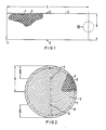
- a quasi-round-conical (or barrel-shaped, or hemispherical) end face shape can also be achieved with the honeycomb bodies according to the invention.
- a shape of the end faces is more favorable than a flat end face for some applications.
- Claim 12 describes the production of a honeycomb body with a round cross section
- claim 13 specifies the modified production for elongated cross sections
- Claim 14 additionally specifies a method for producing honeycomb bodies with an oval or irregular cross-sectional area. Except for the insertion of suitably shaped filler pieces in the sheet metal stack serving as the starting material, the method does not differ from those already described. In principle, it would also be possible to carry out the filler pieces by means of a suitable insertion device after the sheet stack has been devoured in opposite directions.
- honeycomb body with a round cross section is produced, as described in features a, b and c of claim 12.
- the ends of the structured metal sheets can then be fastened by joining technology and / or in a form-fitting manner only approximately in the middle of the jacket tube in the circumferential direction, preferably by a weld seam running in the circumferential direction around the jacket tube, if the friction forces which are present in any case are insufficient for the following steps.
- the central region of the honeycomb body thus formed is then pressed out to one end side using a stamp or the like.
- the individual sheets may rotate about the only fastening seam in their center, but do not tear away, so that considerable forces can be used for the deformation.
- both ends of each sheet metal layer touch the jacket tube, which makes it possible to connect each sheet metal layer to the jacket tube on both sides.
- the sheet metal layers no longer necessarily have to be connected to one another as a result of their opposing interweaving, however, they can hardly be moved out of position if they are firmly connected over the entire length or at several points of their jacket contact line.
- a technical connection of the ends only with the casing tube brings further advantages in manufacture according to claim 16. For example, only the inside of the casing tube needs to be provided with solder, e.g. B.
- honeycomb structures are generally very difficult to heat up, the jacket tube alone can be brought to the soldering temperature much more easily, for example by means of induction coils or external heat radiation. Apart from the greater elasticity of the honeycomb body according to the invention, this is a further essential advantage for the production.
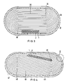
- Figure 1 shows a stack of alternating layers of smooth 1 and corrugated 2 sheets stacked with the height h and length L.
- the stack does not necessarily have to be layered into a cuboid with flat side faces 4 at the beginning of the production process be.
- Other forms, e.g. B. parallelogram or the like may be more advantageous in the manufacture.
- Such a stack 3 is gripped at the fixed points 5, 6 by means of a fork or similarly acting device and devoured in opposite directions by turning the fork or bending the stack ends. In this way, a shape is created as shown schematically in FIG.
- the casing tube can also consist of several segments, for example.
- the individual sheets 1, 2 can be soldered to one another on the end face, preferably in an annular edge zone region 8. In this way, a stable structure is created even if individual layers should not touch the casing tube due to length deviations.
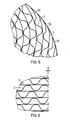
- FIG. 3 shows a correspondingly produced catalyst carrier body with an elongated cross-sectional area, which can be produced from a correspondingly longer stack of sheets 1, 2. Only the fixed points 35, 36 have to be selected offset from one another, which directly results in the desired cross-sectional shape, which fits into a corresponding jacket tube 37. Again, the end faces can be soldered in whole or in part, in particular in the edge zone area 38.
- FIG. 4 Another arrangement of the sheet metal layers 1, 2 in an elongated cross section, which is even more favorable under elasticity and stability considerations, is shown in FIG.
- This arrangement too, can be produced analogously to the previously described methods from a stack of metal sheets by engaging fixed points 45, 46 offset from one another.
- the stack may also have an approximately parallelogram-shaped cross section.
- the individual layers only need to be connected by their ends to the tubular casing 47.
- frontal soldering in particular in the edge zone area 48, is possible.
- the corrugated sheets 2 have straight sections 52 at their ends, which run approximately in the middle between the adjacent smooth sheets 1. With this configuration, the ends of all the sheets have the same scope for contact with the jacket tube, so that they nestle against it and a firm connection to the jacket tube can be accomplished more easily at different contact angles.
- FIG. 6 shows section VI from the edge area of FIG. 1.
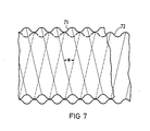
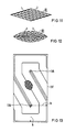
- FIG. 7 shows an alternative structure for the sheet metal layers of the catalyst carrier body according to the invention. Then both sheet metal layers 71, 72 can have corrugations which form a small angle ⁇ with one another.
- This embodiment has the advantage that no smooth sheet metal layers are required as intermediate layers and that in addition the channels formed by the corrugations intersect and communicate with one another, which leads to swirling of the gases and thus better contacting of the surfaces.
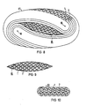
- FIG. 8 shows a further exemplary embodiment of the invention, which makes it clear that oval or more complicated cross sections can also be filled with sheet metal layers using the method according to the invention.
- the catalyst carrier body basically consists of a stack of smooth 1 and corrugated 2 which are intertwined in opposite directions Sheets. The entangling takes place analogously to the exemplary embodiment shown in FIG. 4 around the fixed points 85, 86.
- a filler 81 is additionally required, which is inserted into the stack before or after the entanglement.
- Such a filler 81 must be preformed in accordance with the cross-sectional area still to be filled, and in turn can in turn consist of structured metal sheets. In this way, almost any cross section can be filled within a casing tube 87.
- FIGS. 9, 10, 11 and 12 Suitable filler pieces are shown in FIGS. 9, 10, 11 and 12.
- the filler 81 shown in FIG. 9 consists of layered, different lengths of smooth 1 and corrugated 2 sheet metal strips.
- the filler is made of smooth 1 and corrugated 2 sheet metal strips which are spirally wound one above the other.
- FIGS. 11 and 12 show further variants suitable as filler pieces.
- FIG. 13 shows an example of the multitude of cross sections that can be filled in accordance with the present invention, an end view of a honeycomb body that is rectangular in cross section.
- the fixed points 135, 136 are in turn offset from the stack and have the same distance h on both their narrow sides and on both long sides. To produce such a cross section, however, several deformation steps of the sheet stack are necessary before insertion into the casing tube 137.
- Catalyst carrier bodies constructed according to the invention are insensitive to thermal alternating loads and can therefore be used in the vicinity of the engine with an extended service life.
Abstract
Die vorliegende Erfindung betrifft einen Wabenkörper, insbesondere Katalysator-Trägerkörper, welcher gegen thermische Belastungen und Dehnungen unempfindlich ist und daher eine verlängerte Lebensdauer aufweist. Ein solcher Katalysator-Trägerkörper ist aus lagenweise angeordneten strukturierten Blechen (1, 2), die eine Vielzahl von für Gase durchströmbaren Kanälen bilden, aufgebaut, wobei die Bleche in einem Mantelrohr (7) angeordnet und mit diesem fügetechnisch verbunden sind. Erfindungsgemäß besteht der Katalysator-Trägerkörper aus einem Stapel von strukturierten Blechen (1, 2), dessen Enden jeweils gegensinnig um zwei Fixpunkte (5, 6) verschlungen sind. Die Enden der Bleche (1, 2) sind fügetechnisch mit dem Mantelrohr (7) verbunden, vorzugsweise verlötet. Durch unterschiedliche Wahl der Fixpunkte (5, 6) und ggf. Hinzufügen von Füllstücken lassen sich verschiedene Querschnittsformen herstellen. 
Description
Die vorliegende Erfindung betrifft einen Wabenkörper, insbesondere Katalysator-Trägerkörper, nach dem Oberbegriff des Anspruchs 1, wie er vorzugsweise bei Kraftfahrzeugen angewendet wird.The present invention relates to a honeycomb body, in particular a catalyst carrier body, according to the preamble of
Solche Wabenkörper, z. B. als Katalysator-Trägerkörper und die bei diesem Aufbau auftretenden Probleme bez. Dehnung und thermischer Belastung sind beispielsweise in der EP-A-0 121 174 und der DE-A-33 12 944 beschrieben. Für spiralförmig gewickelte und untereinander verlötete Blechlagen sind verschiedene Lösungen zur Beherrschung der Dehnungsprobleme beschrieben.Such honeycomb bodies, e.g. B. as a catalyst support body and the problems encountered with this structure. Elongation and thermal stress are described, for example, in EP-A-0 121 174 and DE-A-33 12 944. Various solutions for controlling the expansion problems are described for spirally wound and soldered sheet metal layers.
Aufgabe der vorliegenden Erfindung ist es, die Probleme bez. Dehnung und Temperaturverteilung durch einen geeigneten Aufbau zu beherrschen, insbesondere um die Lebensdauer solcher Katalysator-Trägerkörper auch unter extremen Belastungen zu erhöhen.The object of the present invention is to relate the problems. Controlling expansion and temperature distribution using a suitable structure, in particular in order to increase the service life of such catalyst carrier bodies even under extreme loads.
Zur Lösung dieser Aufgabe wird ein Wabenkörper gemäß dem Anspruch 1 vorgeschlagen, welcher aus einem Stapel von gegensinnig verschlungenen Blechen besteht. Dieser Aufbau führt durch die verschlungene Form der Bleche und dadurch, daß diese an ihren Enden mit dem Mantelrohr fügetechnisch verbunden werden können, zu einem sehr stabilen, aber bei Dehnungen auch sehr elastischen Aufbau.To achieve this object, a honeycomb body is proposed, which consists of a stack of sheets intertwined in opposite directions. This structure leads to a very stable, but also very elastic structure when stretched due to the convoluted shape of the sheets and the fact that they can be joined at their ends to the casing tube.
Wie sich aus Anspruch 2 ergibt, muß der Stapel, welcher zu dem späteren Wabenkörper verschlungen wird, im Querschnitt den gleichen Flächeninhalt haben wie der spätere Wabenkörper. Dadurch ergibt sich je nach der gewählten Höhe des Stapels für runde Querschnittsformen immer eine bestimmte Länge. Um besonders elastische Formen zu erhalten, sollte der Stapel vorzugsweise eine Höhe von einem Drittel bis einem Fünftel oder sogar einem Neuntel des Durchmessers des herzustellenden Wabenkörpers haben. Andere Höhenverhältnisse sind jedoch problemlos möglich. Wie im Anspruch 3 angegeben, ist es gemäß dem Erfindungsgedanken auch möglich, langgestreckte runde oder auch eckige Querschnitte von Wabenkörpern auf ähnliche Weise mit strukturierten Blechen zu füllen. Der Unterschied bei der Herstellung und dem späteren Aussehen liegt hauptsächlich in der Anordnung der Fixpunkte und ggf. in der Form des Stapels, wie anhand der Zeichnung näher erläutert wird.As can be seen from
Für bestimmte Anwendungsfälle ist es gemäß Anspruch 4 möglich, die erfindungsgemäßen Wabenkörper zusätzlich stirnseitig ganz oder zumindest in Teilbereichen untereinander zu verlöten. Da nicht in allen Fällen sichergestellt werden kann, daß jede einzelne Lage an beiden Enden das Mantelrohr berührt, kann es hilfreich sein, in einem schmalen Randzonenbereich die strukturierten Bleche zusätzlich untereinander zu verlöten, um eine sichere Halterung zu gewährleisten.For certain applications, it is possible according to claim 4 to additionally solder the honeycomb bodies according to the invention entirely or at least in partial areas to one another. Since it cannot be ensured in all cases that each individual layer touches the casing tube at both ends, it can be helpful to additionally solder the structured metal sheets to one another in a narrow edge zone area in order to ensure secure mounting.
Gemäß dem Anspruch 5 werden auch bei der vorliegenden Erfindung abwechselnde Lagen von glatten und gewellten Blechen bevorzugt. Dies ist jedoch nur eine von vielen möglichen Ausführungsformen, da auch andere bekannte Strukturen, z. B. Doppelwellenstrukturen oder Blechlagen mit omegaförmigen Wellungen verwendbar sind. Bei Verwendung glatter und gewellter Bleche jedoch ist es gemäß Anspruch 6 vorteilhaft, die glatten Bleche geringfügig länger herzustellen als die gewellten Bleche, so daß die glatten Bleche an beiden Seiten über die gewellten Bleche um eine geringe Länge hinausragen. Die Schichtung eines Stapels mit solchen Blechen erfordert natürlich mehr Aufwand als bei Blechen gleicher Länge, kann aber leicht bewerkstelligt werden.According to
Dafür gelingt es bei einer solchen Anordnung wesentlich leichter, die Enden aller gewellten und glatten Blechlagen mit dem Mantelrohr fügetechnisch zu verbinden, da sich nicht mehr Enden von gewellten Blechlagen zwischen das Mantelrohr und Enden von glatten Blechlagen schieben können.For such an arrangement, however, it is much easier to join the ends of all corrugated and smooth sheet metal layers with the casing tube by joining technology, since no more ends of corrugated sheet metal layers can slide between the casing tube and ends of smooth sheet metal layers.
Ein gleicher Effekt kann gemäß Anspruch 7 auch dadurch erreicht werden, daß die gewellten Bleche an ihren Enden gerade Abschnitte aufweisen, welche etwa mittig zwischen den angrenzenden glatten Blechen verlaufen. Auch bei dieser Ausgestaltung berühren die Enden aller Blechlagen gleichförmig das Mantelrohr, und zwar schmiegen sie sich vorzugsweise an dieses an, wodurch eine feste Verbindung erleichtert wird.A similar effect can also be achieved according to claim 7 in that the corrugated sheets have straight sections at their ends, which run approximately in the middle between the adjacent smooth sheets. In this embodiment, too, the ends of all sheet metal layers uniformly touch the casing tube, and they preferably nestle against it, which facilitates a firm connection.
Eine weitere Ausführungsform der Erfindung wird in Anspruch 8 vorgeschlagen. Eine derartige Anordnung ist im Prinzip für Filter aus der EP-A-0 025 584 bekannt. Durch Verwendung abwechselnd angeordneter gewellter Bleche, deren Wellung untereinander einen kleinen Winkel bildet, lassen sich verschiedene Vorteile erreichen, beispielsweise eine gewisse Quervermischung zwischen den einzelnen Abgaskanälen und eine geringfügig unregelmäßige Stirnfläche, welche den dort auftretenden Druckverlust über eine kurze Länge verteilt. Die Anwendung eines solchen Aufbaues war bisher für spiralig gewickelte Katalysator-Trägerkörper kaum zu verwirklichen, da eine schräge Wellung äußerst schwierig herzustellen ist. Ineinander greifende Zahnwalzen mit einer schrägen Zahnung verformen nämlich im allgemeinen einen Blechstreifen sehr stark, so daß längere Stücke mit einer feinen gleichmäßigen schrägen Wellung kaum herstellbar sind. Bei der vorliegenden Erfindung werden jedoch nur relativ kurze Stücke benötigt, welche sogar von einem einzigen Zahnwalzenpaar hergestellt werden können. Dazu brauchen lediglich Bleche mit vorbestimmter Länge jeweils abwechselnd mit geringfügiger Schrägstellung zu der einen bzw. anderen Seite in ein genügend breites Zahnwalzenpaar eingeführt zu werden, wobei hinter dem Zahnwalzenpaar diese Bleche wieder zu einem Stapel zusammengeführt werden. Im übrigen ergeben sich praktisch keine Veränderungen im Herstellungsverfahren gegenüber anders strukturierten Blechen, da der sehr kleine Winkel zwischen den Wellungen die Handhabung ansonsten kaum beeinflußt.Another embodiment of the invention is proposed in claim 8. Such an arrangement is known in principle for filters from EP-A-0 025 584. By using alternately arranged corrugated sheets, the corrugation of which forms a small angle with one another, various advantages can be achieved, for example a certain cross-mixing between the individual exhaust gas channels and a slightly irregular end face, which distributes the pressure loss occurring there over a short length. The use of such a structure has hitherto hardly been possible for spiral-wound catalyst carrier bodies, since an oblique corrugation is extremely difficult to produce. Interlocking toothed rollers with oblique teeth generally deform a sheet metal strip very strongly, so that longer pieces with a fine, uniform oblique corrugation can hardly be produced. In the present invention, however, only relatively short pieces are required, which can even be produced by a single pair of toothed rollers. To do this, only sheets with a predetermined length need to be inserted alternately with a slight inclination to one or the other side in a sufficiently wide pair of toothed rollers, behind which Toothed roller pair of these sheets are brought together again in a stack. Otherwise, there are practically no changes in the manufacturing process compared to differently structured sheets, since the very small angle between the corrugations otherwise hardly affects the handling.
In Anspruch 9 wird weiterhin vorgeschlagen, daß die Bleche durch etwa in Umfangsrichtung verlaufende Schweißnähte an ihren Enden mit dem Mantelrohr verbunden sein sollen. Dabei kann die Haltbarkeit dieser Verbindungen dadurch verstärkt werden, daß durch geeignete Wahl der Schweißparameter die Schweißwurzel etwas nach innen einsinkt, so daß zusätzlich eine Formschlußverbindung zwischen dem Mantelrohr und den Enden der Bleche entsteht.In
Für bestimmte Anwendungsfälle werden ggf. Querschnittsformen benötigt, welche sich nach dem bisher beschriebenen System nicht vollständig mit einem gegensinnig verschlungenen Blechstapel ausfüllen lassen. Unregelmäßige Querschnittsformen, insbesondere aber auch ovale Querschnittsformen, welche ein günstigeres Stabilitätsverhalten bei relativ hohem Innendruck aufweisen, lassen sich jedoch erfindungsgemäß herstellen, wenn Füllstücke verwendet werden, welche die überschüssige Querschnittsfläche ausfüllen und ihrerseits wiederum aus strukturierten Blechen gewickelt oder geschichtet sein können.For certain applications, cross-sectional shapes may be required, which, according to the system described so far, cannot be completely filled with a sheet pile stacked in opposite directions. Irregular cross-sectional shapes, but in particular also oval cross-sectional shapes, which have a more favorable stability behavior at a relatively high internal pressure, can, however, be produced according to the invention if filler pieces are used which fill the excess cross-sectional area and which in turn can be wound or layered from structured sheets.
Gemäß Anspruch 11 läßt sich bei den erfindungsgemäßen Wabenkörpern auch eine quasi-rund-konische (oder tonnenförmige, bzw. halbkugelförmige) Stirnseitenform erreichen. Eine solche Form der Stirnseiten ist strömungstechnisch für manche Anwendungen günstiger als eine ebene Stirnfläche. Zwar läßt sich nicht genau die gleiche Form erreichen, wie sie durch teleskopartiges Auseinanderziehen bei spiralig gewickelten Katalysator-Trägerkörpern entsteht, jedoch ist ein ähnlicher Effekt erreichbar, und zwar um so leichter, je kleiner die Höhe des für die Herstellung eines solchen Wabenkörpers verwendeten Blechstapels ist.According to claim 11, a quasi-round-conical (or barrel-shaped, or hemispherical) end face shape can also be achieved with the honeycomb bodies according to the invention. In terms of flow technology, such a shape of the end faces is more favorable than a flat end face for some applications. Although it is not possible to achieve exactly the same shape as is produced by telescopically pulling apart in the case of spirally wound catalyst carrier bodies, a similar effect can be achieved, and the easier the smaller the height of the one used for the production of such a honeycomb body Sheet stack is.
In den Ansprüchen 12, 13, 14, 15 und 16 werden beispielhaft einige Herstellungsverfahren zur Herstellung der erfindungsgemäßen Wabenkörper beschrieben. Anspruch 12 beschreibt die Herstellung eines Wabenkörpers mit rundem Querschnitt, während Anspruch 13 die modifizierte Herstellung für langgestreckte Querschnitte angibt. Im Anspruch 14 wird zusätzlich ein Verfahren zur Herstellung von Wabenkörpern mit ovaler oder unregelmäßiger Querschnittsfläche angegeben. Bis auf das Einlegen geeignet geformter Füllstücke in den als Ausgangsmaterial dienenden Blechstapel unterscheidet sich das Verfahren nicht von den bereits beschriebenen. Grundsätzlich wäre es auch möglich, die Füllstücke mittels einer geeigneten Einführvorrichtung nach dem gegensinnigen Verschlingen des Blechstapels vorzunehmen.In
Eine weitere Herstellungsvariante ist im Anspruch 15 angegeben. Zunächst wird ein Wabenkörper mit rundem Querschnitt hergestellt, wie in den Merkmalen a, b und c des Anspruchs 12 beschrieben. Die Enden der strukturierten Bleche können dann fügetechnisch und/oder formschlüssig nur etwa in der Mitte des Mantelrohres in Umfangsrichtung befestigt werden, vorzugsweise durch eine in Umfangsrichtung um das Mantelrohr verlaufende Schweißnaht, falls die ohnehin vorhandenen Reibungskräfte für die folgenden Schritte nicht ausreichen. Anschließend wird mit einem Stempel oder dergleichen der Zentralbereich des so gebildeten Wabenkörpers zu einer Stirnseite herausgedrückt. Die einzelnen Bleche drehen sich dabei ggf. um die einzige Befestigungsnaht in ihrer Mitte, reißen jedoch nicht los, so daß für die Verformung erhebliche Kräfte aufgewendet werden können. Es entsteht eine etwa rund-konische, halbkugelförmige oder tonnenförmige Stirnseite, wobei die einzelnen Kanäle nicht mehr ganz exakt in axialer Richtung des Katalysator-Trägerkörpers verlaufen, was jedoch keine Nachteile mit sich bringt. Der so verformte Wabenkörper wird durch (weitere) fügetechnische und/oder formschlüssige Verbindungen der Bleche zum Mantelrohr befestigt.Another manufacturing variant is specified in claim 15. First, a honeycomb body with a round cross section is produced, as described in features a, b and c of
Hervorzuheben ist noch, daß bei allen erfindungsgemäß hergestellten Katalysator-Trägerkörpern im Prinzip beide Enden jeder Blechlage das Mantelrohr berühren, wodurch eine beidseitige fügetechnische Verbindung jeder Blechlage mit dem Mantelrohr möglich wird. Untereinander brauchen die Blechlagen dadurch nicht mehr unbedingt verbunden zu werden, da sie sich wegen ihrer gegensinnigen Verschlingung trotzdem kaum aus ihrer Lage bringen lassen, wenn sie über die ganze Länge oder an mehreren Stellen ihrer Mantelberührungslinie fügetechnisch fest verbunden sind. Eine fügetechnische Verbindung der Enden nur mit dem Mantelrohr bringt gemäß Anspruch 16 weitere Vorteile bei der Herstellung mit sich. So braucht beispielsweise nur noch die Innenseite des Mantelrohres mit Lot versehen zu werden, z. B. in Form von Lotpulver, -Paste, oder -Folie, und beim Lötvorgang ist auch nur eine Aufwärmung des Mantelrohres auf Löttemperatur nötig. Während sich Wabenstrukturen insgesamt sehr schlecht aufheizen lassen, kann das Mantelrohr allein sehr viel leichter auf Löttemperatur gebracht werden, beispielsweise durch Induktionsspulen oder Wärmebestrahlung von außen. Dies ist, abgesehen von der größeren Elastizität des erfindungsgemäßen Wabenkörpers ein weiterer wesentlicher Vorteil für die Herstellung.It should also be emphasized that in all catalyst carrier bodies produced according to the invention, in principle both ends of each sheet metal layer touch the jacket tube, which makes it possible to connect each sheet metal layer to the jacket tube on both sides. The sheet metal layers no longer necessarily have to be connected to one another as a result of their opposing interweaving, however, they can hardly be moved out of position if they are firmly connected over the entire length or at several points of their jacket contact line. A technical connection of the ends only with the casing tube brings further advantages in manufacture according to claim 16. For example, only the inside of the casing tube needs to be provided with solder, e.g. B. in the form of solder powder, paste, or foil, and only a warm-up of the jacket tube to the soldering temperature is necessary during the soldering process. While honeycomb structures are generally very difficult to heat up, the jacket tube alone can be brought to the soldering temperature much more easily, for example by means of induction coils or external heat radiation. Apart from the greater elasticity of the honeycomb body according to the invention, this is a further essential advantage for the production.
Ausführungsbeispiele der Erfindung werden anhand von schematischen Querschnitten bzw. Stirnansichten erfindungsgemäßer Wabenkörper näher erläutert. Es zeigen
Figur 1 einen Blechstapel zu Beginn des Herstellungsprozesses,Figur 2 einen daraus durch gegensinnige Verschlingung hergestellten Katalysator-Trägerkörper,Figur 3 schematisch den Aufbau eines Katalysator-Trägerkörpers mit langgestrecktem Querschnitt,- Figur 4 ebenfalls einen Katalysator-Trägerkörper mit langgestrecktem Querschnitt aber mit diagonal verlaufenden, verschlungenen Blechschichten,
Figur 5 den Ausschnitt V aus dem Randbereich von Figur 4,Figur 6 den Ausschnitt VI aus dem Randbereich vonFigur 1,- Figur 7 zwei Blechlagen, deren Wellung einen kleinen Winkel untereinander bildet,
- Figur 8 den Aufbau eines Katalysator-Trägerkörpers mit ovalem Querschnitt,
Figur 9 den Aufbau desFüllstückes 81 aus Figur 8,Figuren 10, 11, 12 alternative Ausgestaltungen des Füllstückes und- Figur 13 den Aufbau eines Katalysator-Trägerkörpers mit rechteckigem Querschnitt.
- FIG. 1 shows a stack of metal sheets at the start of the manufacturing process,
- FIG. 2 shows a catalyst carrier body produced therefrom by intertwining in opposite directions,
- FIG. 3 shows schematically the structure of a catalyst carrier body with an elongated cross section,
- Figure 4 also with a catalyst carrier elongated cross section but with diagonally running, intertwined sheet metal layers,
- FIG. 5 shows section V from the edge area of FIG. 4,
- FIG. 6 shows section VI from the edge area of FIG. 1,
- FIG. 7 two sheet metal layers, the corrugation of which forms a small angle with one another,
- FIG. 8 shows the structure of a catalyst carrier body with an oval cross section,
- FIG. 9 shows the structure of the filling
piece 81 from FIG. 8, - Figures 10, 11, 12 alternative configurations of the filler and
- Figure 13 shows the structure of a catalyst carrier body with a rectangular cross section.
Figur 1 zeigt einen aus abwechselnden Lagen glatter 1 und gewellter 2 Bleche geschichteten Stapel mit der Höhe h und der Länge L. Je nach Fertigungsmethode und gewünschtem, herzustellendem Querschnitt braucht der Stapel zu Beginn des Herstellungsvorganges nicht unbedingt zu einem Quader mit ebenen Seitenflächen 4 geschichtet zu sein. Andere Formen, z. B. Parallelogramm oder dergleichen, können bei der Herstellung vorteilhafter sein. Ein solcher Stapel 3 wird mittels einer Gabel oder ähnlich fixierend wirkenden Vorrichtung an den Fixpunkten 5, 6 gefaßt und durch Drehen der Gabel bzw. Umbiegen der Stapelenden gegensinnig verschlungen. Auf diese Weise entsteht eine Form, wie sie schematisch in Figur 2 dargestellt ist. So verschlungene Bleche lassen sich in einem Mantelrohr 7 fügetechnisch befestigen, wodurch ein elastischer, aber doch stabiler Katalysator-Trägerkörper entsteht. Grundsätzlich kann das Mantelrohr auch beispielsweise aus mehreren Segmenten bestehen. Zur Verbesserung der Stabilität können die einzelnen Bleche 1, 2 stirnseitig, vorzugsweise in einem ringförmigen Randzonenbereich 8 untereinander verlötet sein. Auf diese Weise entsteht ein stabiles Gefüge auch dann, wenn einzelne Lagen aufgrund von Längenabweichungen das Mantelrohr nicht berühren sollten.Figure 1 shows a stack of alternating layers of smooth 1 and corrugated 2 sheets stacked with the height h and length L. Depending on the manufacturing method and the desired cross section to be produced, the stack does not necessarily have to be layered into a cuboid with flat side faces 4 at the beginning of the production process be. Other forms, e.g. B. parallelogram or the like may be more advantageous in the manufacture. Such a
In Figur 3 ist ein entsprechend hergestellter Katalysator-Trägerkörper mit langgestreckter Querschnittsfläche dargestellt, wobei dieser aus einem entsprechend längeren Stapel von Blechen 1, 2 herstellbar ist. Lediglich die Fixpunkte 35, 36 müssen gegeneinander versetzt gewählt werden, wodurch sich direkt die gewünschte Querschnittsform ergibt, welche in ein entsprechendes Mantelrohr 37 hineinpaßt. Wiederum können die Stirnseiten ganz oder teilweise, insbesondere im Randzonenbereich 38 verlötet sein.FIG. 3 shows a correspondingly produced catalyst carrier body with an elongated cross-sectional area, which can be produced from a correspondingly longer stack of
Eine andere, unter Elastizitäts- und Stabilitätsüberlegungen noch günstigere Anordnungen der Blechlagen 1, 2 in einem langgestreckten Querschnitt ist in Figur 4 dargestellt. Auch diese Anordnung läßt sich analog den bisher beschriebenen Verfahren aus einem Blechstapel durch Angreifen an gegeneinander versetzten Fixpunkten 45, 46 herstellen. Der Stapel kann ggf. dabei allerdings zusätzlich einen etwa parallelogrammförmigen Querschnitt aufweisen. Auch bei der in Figur 4 gezeigten Ausführung brauchen die einzelnen Lagen nur mit ihren Enden an dem Mantelrohr 47 fügetechnisch verbunden zu werden. Eine stirnseitige Verlötung, insbesondere im Randzonenbereich 48 ist jedoch möglich.Another arrangement of the
Es sei darauf hingewiesen, daß bei den Ausführungsbeispielen der Figuren 2, 3 und 4 im allgemeinen die glatten äußeren Blechlagen 9, 39 bzw. 49 des Ausgangsstapels gegeneinander gefaltet werden, so daß diese Schicht aus einer doppelten glatten Blechlage besteht. Dies kann natürlich prinzipiell vermieden werden, indem die oberste bzw. unterste Blechlage des Stapels direkt neben den Fixpunkten abgeschnitten wird. Von großer Bedeutung ist eine solche Maßnahme jedoch nicht, da die Bleche ohnehin sehr dünn sind.It should be pointed out that in the exemplary embodiments of FIGS. 2, 3 and 4 the smooth
In Figur 5 ist der Ausschnitt V aus dem Randbereich der Figur 4 vergrößert dargestellt. Gemäß diesem Ausführungsbeispiel weisen die gewellten Bleche 2 an ihren Enden gerade Abschnitte 52 auf, welche etwa mittig zwischen den angrenzenden glatten Blechen 1 verlaufen. Durch diese Ausgestaltung haben die Enden aller Bleche den gleichen Spielraum für eine Berührung mit dem Mantelrohr, so daß sie sich an dieses anschmiegen und eine feste Verbindung zum Mantelrohr bei verschiedenen Berührungswinkeln leichter bewerkstelligt werden kann.In FIG. 5, the detail V from the edge area of FIG. 4 is shown enlarged. According to this exemplary embodiment, the
Das gleiche Ergebnis läßt sich durch eine Ausführungsform gemäß Figur 6, welche den Ausschnitt VI aus dem Randbereich der Figur 1 zeigt, erreichen. Durch Verkürzung der gewellten Blechlagen 2 gegenüber den glatten Blechlagen 1 um einen Abstand d wird ebenfalls erreicht, daß alle Enden der Blechlagen das Mantelrohr berühren und sich daran anschmiegen können. Um einen gleichmäßigen Stapel aus längeren glatten Blechen 1 und kürzeren gewellten Blechen 2 herstellen zu können, kann es vorteilhaft sein, die glatten Bleche an ihren Enden mit Nuten der Tiefe d zu versehen, in welche beim Stapeln Querstäbe eingesetzt werden, zwischen denen die gewellten Bleche 2 ihre genaue Position einnehmen können.The same result can be achieved by an embodiment according to FIG. 6, which shows section VI from the edge area of FIG. 1. By shortening the corrugated
Figur 7 zeigt eine alternative Struktur für die Blechlagen des erfindungsgemäßen Katalysator-Trägerkörpers. Danach können beide Blechlagen 71, 72 Wellungen aufweisen, welche untereinander einen kleinen Winkel α bilden. Diese Ausführungsform hat den Vorteil, daß keine glatten Blechlagen als Zwischenlagen benötigt werden und daß zusätzlich die durch die Wellungen gebildeten Kanäle sich untereinander kreuzen und miteinander kommunizieren, was zu einer Verwirbelung der Gase und damit einer besseren Kontaktierung der Oberflächen führt.FIG. 7 shows an alternative structure for the sheet metal layers of the catalyst carrier body according to the invention. Then both sheet metal layers 71, 72 can have corrugations which form a small angle α with one another. This embodiment has the advantage that no smooth sheet metal layers are required as intermediate layers and that in addition the channels formed by the corrugations intersect and communicate with one another, which leads to swirling of the gases and thus better contacting of the surfaces.
In Figur 8 ist ein weiteres Ausführungsbeispiel der Erfindung dargestellt, welches deutlich macht, daß auch ovale oder kompliziertere Querschnitte nach dem erfindungsgemäßen Verfahren mit Blechlagen ausgefüllt werden können. Wiederum besteht der Katalysator-Trägerkörper prinzipiell aus einem Stapel gegensinnig verschlungener glatter 1 und gewellter 2 Bleche. Die Verschlingung erfolgt analog zu dem in Figur 4 dargestellten Ausführungsbeispiel um die Fixpunkte 85, 86. Um jedoch den ganzen Querschnitt ausfüllen zu können, wird zusätzlich ein Füllstück 81 benötigt, welches vor oder nach der Verschlingung des Stapels in diesen eingesetzt wird. Ein solches Füllstück 81 muß entsprechend der noch aufzufüllenden Querschnittsfläche vorgeformt sein und kann seinerseits wiederum aus strukturierten Blechen bestehen. Auf diese Weise läßt sich fast jeder Querschnitt innerhalb eines Mantelrohres 87 ausfüllen.FIG. 8 shows a further exemplary embodiment of the invention, which makes it clear that oval or more complicated cross sections can also be filled with sheet metal layers using the method according to the invention. Again, the catalyst carrier body basically consists of a stack of smooth 1 and corrugated 2 which are intertwined in opposite directions Sheets. The entangling takes place analogously to the exemplary embodiment shown in FIG. 4 around the fixed
In den Figuren 9, 10, 11 und 12 werden geeignete Füllstücke dargestellt. Das in Figur 9 gezeigte Füllstück 81 besteht aus geschichteten, unterschiedlich langen glatten 1 und gewellten 2 Blechstreifen. In Figur 10 ist das Füllstück aus spiralig übereinander gewickelten glatten 1 und gewellten 2 Blechstreifen hergestellt. Die Figuren 11 und 12 zeigen weitere als Füllstücke geeignete Varianten.Suitable filler pieces are shown in FIGS. 9, 10, 11 and 12. The
In Figur 13 ist beispielhaft für die Vielzahl der gemäß vorliegender Erfindung ausfüllbaren Querschnitte eine Stirnansicht eines im Querschnitt rechteckigen Wabenkörpers gezeigt. Die Fixpunkte 135, 136 liegen wiederum versetzt zu dem Stapel und haben sowohl zu ihrer jeweiligen Schmalseite wie zu beiden Längsseiten den gleichen Abstand h. Zur Herstellung eines solchen Querschnittes sind vor dem Einsetzen in das Mantelrohr 137 jedoch mehrere Verformungsschritte des Blechstapels nötig.FIG. 13 shows an example of the multitude of cross sections that can be filled in accordance with the present invention, an end view of a honeycomb body that is rectangular in cross section. The
Erfindungsgemäß aufgebaute Katalysator-Trägerkörper sind unempfindlich gegen thermische Wechselbelastungen und können daher bei verlängerter Lebensdauer im motornahen Bereich eingesetzt werden.Catalyst carrier bodies constructed according to the invention are insensitive to thermal alternating loads and can therefore be used in the vicinity of the engine with an extended service life.
Claims (17)
gekennzeichnet durch folgende Merkmale:
characterized by the following features:
gekennzeichnet durch folgende Merkmale:
characterized by the following features:
Priority Applications (1)
| Application Number | Priority Date | Filing Date | Title |
|---|---|---|---|
| AT87106405T ATE45781T1 (en) | 1986-05-12 | 1987-05-04 | HONEYCOMB BODY, IN PARTICULAR CATALYST CARRIER|BODY, WITH METAL SHEET LAYERS INTERLOCKED IN OPPOSITIONS AND PROCESS FOR ITS MANUFACTURE. |
Applications Claiming Priority (2)
| Application Number | Priority Date | Filing Date | Title |
|---|---|---|---|
| DE3615902 | 1986-05-12 | ||
| DE3615902 | 1986-05-12 |
Publications (2)
| Publication Number | Publication Date |
|---|---|
| EP0245737A1 true EP0245737A1 (en) | 1987-11-19 |
| EP0245737B1 EP0245737B1 (en) | 1989-08-23 |
Family
ID=6300625
Family Applications (1)
| Application Number | Title | Priority Date | Filing Date |
|---|---|---|---|
| EP87106405A Expired EP0245737B1 (en) | 1986-05-12 | 1987-05-04 | Honeycomb body, particularly a catalyst carrier, provided with opposedly folded metal sheet layers, and its manufacturing process |
Country Status (10)
| Country | Link |
|---|---|
| US (2) | US4832998A (en) |
| EP (1) | EP0245737B1 (en) |
| JP (1) | JPS62273051A (en) |
| KR (1) | KR950013327B1 (en) |
| AT (1) | ATE45781T1 (en) |
| BR (1) | BR8702369A (en) |
| CA (1) | CA1270204A (en) |
| DE (1) | DE3760479D1 (en) |
| ES (1) | ES2010201B3 (en) |
| GR (2) | GR880300176T1 (en) |
Cited By (27)
| Publication number | Priority date | Publication date | Assignee | Title |
|---|---|---|---|---|
| DE3818512A1 (en) * | 1988-05-31 | 1989-12-07 | Interatom | METHOD FOR GLUING AND SOLDERING A METAL CATALYST SUPPORT BODY AND RELATED DEVICE |
| DE4112354A1 (en) * | 1991-04-16 | 1992-10-22 | Behr Gmbh & Co | DEVICE FOR CATALYTIC DETOXING OF EXHAUST GAS |
| DE4233404A1 (en) * | 1992-10-05 | 1994-04-07 | Degussa | Supported metal catalyst with a matrix made of catalytically coated metal strips welded into a jacket tube |
| US5328774A (en) * | 1990-08-06 | 1994-07-12 | Emitec Gesellschaft Fur Emissionstechnologie Mbh | Monolithic metal honeycomb body with varying number of channels |
| US5355671A (en) * | 1990-10-15 | 1994-10-18 | Emitec Gesellschaft Fur Emmissionstechnologie mbH | Method and apparatus for monitoring the function of a catalytic converter |
| DE4409026A1 (en) * | 1994-03-16 | 1995-11-09 | Bayerische Motoren Werke Ag | Exhaust gas catalytic converter, in particular for internal combustion engines |
| DE19514986A1 (en) * | 1995-04-24 | 1996-10-31 | Audi Ag | Catalyser converting harmful exhaust components |
| DE19521685A1 (en) * | 1995-06-14 | 1996-12-19 | Emitec Emissionstechnologie | Device and method for producing a honeycomb body |
| CN1035894C (en) * | 1992-05-14 | 1997-09-17 | 埃米特放射技术股份有限公司 | Apparatus for catalytic exhaust gas cleaning |
| WO1999061151A1 (en) * | 1998-05-26 | 1999-12-02 | Emitec Gesellschaft Für Emissionstechnologie Mbh | Monolithic, metallic honeycomb bodies with a number of varying channels |
| EP0919280A3 (en) * | 1997-09-05 | 2000-01-19 | Kemira Metalkat Oy | Honeycomb structure for a catalyst |
| US6109386A (en) * | 1998-02-03 | 2000-08-29 | Emitec Gesellschaft Fuer Emissionstechnologie Mbh | Honeycomb body with a flattened cross-sectional region and a method for producing the honeycomb body |
| WO2000068550A1 (en) * | 1999-05-10 | 2000-11-16 | Emitec Gesellschaft Für Emissionstechnologie Mbh | Honeycomb body structure comprising various sections in a casing tube |
| WO2001019561A1 (en) * | 1999-09-14 | 2001-03-22 | Emitec Gesellschaft Für Emissionstechnologie Mbh | Method and device for joining a support matrix of a honeycomb on the end face using bonding technology |
| WO2003087548A1 (en) | 2002-04-18 | 2003-10-23 | Emitec Gesellschaft Für Emissionstechnologie Mbh | Catalyst support body with corrugated sleeve and method for production thereof |
| WO2003087549A1 (en) * | 2002-04-18 | 2003-10-23 | Emitec Gesellschaft Für Emissionstechnologie Mbh | Calibrated catalyst carrier element comprising a corrugated sheath and method for the production thereof |
| WO2004063541A1 (en) * | 2003-01-09 | 2004-07-29 | Emitec Gesellschaft Für Emissionstechnologie Mbh | Method for treating a fluid and honeycomb body |
| WO2005033484A1 (en) * | 2003-10-02 | 2005-04-14 | Emitec Gesellschaft Für Emissionstechnologie Mbh | Method for the production of a metallic honeycomb element comprising layers with different lengths |
| US7011893B2 (en) | 2002-08-02 | 2006-03-14 | Emitec Gesellschaft Fuer Emissionstechnologie Mbh | Metallic layer with regions of varying material thickness, method for producing such a metallic layer and honeycomb body at least partly produced from such metallic layers |
| US7197822B2 (en) | 2003-06-27 | 2007-04-03 | Emitec Gesellschaft Für Emissionstechnologie Mbh | Metallic honeycomb structure and process for producing the same |
| US7404254B2 (en) | 2002-04-18 | 2008-07-29 | Emitec Gesellschaft Fuer Emissions Technologie Mbh | Calibrated catalyst carrier body with corrugated casing and method for manufacturing the same |
| DE102007010759A1 (en) | 2007-03-06 | 2008-09-11 | Emitec Gesellschaft Für Emissionstechnologie Mbh | Method for producing a honeycomb body and corresponding honeycomb body |
| US7476366B2 (en) | 2002-04-18 | 2009-01-13 | Emitec Gesellschaft Fuer Emissionstechnologie Mbh | Catalyst carrier body with corrugated casing and process for producing the same |
| DE102009035612A1 (en) | 2009-07-31 | 2011-02-03 | Emitec Gesellschaft Für Emissionstechnologie Mbh | Method for soldering a honeycomb body for vehicle with a combustion engine, comprises inserting the honeycomb body into a fixing means, soldering the honeycomb body and removing the fixing means from the honeycomb body |
| DE102016125640A1 (en) | 2016-12-23 | 2018-06-28 | Karlsruher Institut Für Technologie (Kit) | Process for producing a metallic shaped body |
| DE102016125641A1 (en) | 2016-12-23 | 2018-06-28 | Karlsruher Institut Für Technologie (Kit) | Process for producing a natural gas substition from hydrogen-containing gas mixtures |
| US11192058B2 (en) | 2016-05-25 | 2021-12-07 | Vitesco Technologies GmbH | Honeycomb body for exhaust gas aftertreatment |
Families Citing this family (107)
| Publication number | Priority date | Publication date | Assignee | Title |
|---|---|---|---|---|
| ATE52836T1 (en) * | 1987-01-15 | 1990-06-15 | Emitec Emissionstechnologie | METALLIC CATALYST CARRIER WITH SHORTENED JACKET. |
| DE8801788U1 (en) * | 1988-02-11 | 1989-06-15 | Emitec Emissionstechnologie | |
| DE3809105A1 (en) * | 1988-03-18 | 1989-09-28 | Eberspaecher J | DEVICE FOR CATALYTICALLY PURIFYING THE EXHAUST GASES OF AN INTERNAL COMBUSTION ENGINE AND METHOD FOR THE PRODUCTION THEREOF |
| DE8816514U1 (en) * | 1988-04-25 | 1989-10-26 | Emitec Emissionstechnologie | |
| DE8810816U1 (en) * | 1988-08-26 | 1989-12-21 | Emitec Emissionstechnologie | |
| WO1990003220A1 (en) * | 1988-09-22 | 1990-04-05 | Emitec Gesellschaft Für Emissionstechnologie Mbh | Honeycomb structure, in particular catalyst support, composed of a plurality of interlaced bundles of sheet metal |
| US5135794A (en) * | 1988-09-22 | 1992-08-04 | Emitec Gesellschaft Fur Emissionstechnologie Mbh | Honeycomb body, in particular catalyst carrier body, formed of a plurality of entwined bundles of sheet metal |
| EP0389645B1 (en) * | 1988-10-04 | 1995-03-22 | Nippon Steel Corporation | Metal carrier having thermal fatigue resistance for automobile exhaust gas cleaning catalysts |
| US5403558A (en) * | 1988-10-04 | 1995-04-04 | Nippon Steel Corporation | Heat and fatigue resistant metallic carrier for automobile exhaust gas-purifying catalyst |
| DE8812762U1 (en) * | 1988-10-11 | 1989-06-29 | Emitec Emissionstechnologie | |
| US5190732A (en) * | 1988-10-11 | 1993-03-02 | Emitec Gesellschaft Fur Emissionstechnologie Mbh | Catalyst with a double casing system |
| JPH0541782Y2 (en) * | 1989-04-10 | 1993-10-21 | ||
| IT1232749B (en) * | 1989-04-12 | 1992-03-05 | I R T I Istituto Di Ricerca E | EXHAUST GAS PURIFIER WITH CATALYTIC ACTIVITY AND SILENCER FOR INTERNAL COMBUSTION ENGINES |
| JPH0823409B2 (en) * | 1989-06-20 | 1996-03-06 | エミテツク ゲゼルシヤフト フユア エミツシオンス テクノロギー ミツト ベシユレンクテル ハフツング | Method and apparatus for heat generation by flameless combustion of fuel in a gas stream |
| JP2890503B2 (en) * | 1989-07-26 | 1999-05-17 | 株式会社日本自動車部品総合研究所 | Porous carrier |
| DE8909128U1 (en) * | 1989-07-27 | 1990-11-29 | Emitec Emissionstechnologie | |
| FR2656376B1 (en) * | 1989-12-22 | 1994-04-29 | Rosi Ets | EXHAUST, ESPECIALLY CATALYTIC, FOR BURNED GASES FROM INTERNAL COMBUSTION ENGINES. |
| ES2050049T3 (en) * | 1989-12-22 | 1994-05-01 | Emitec Emissionstechnologie | EXHAUST GAS DUCT WITH CATALYST SUPPORT BODY ATTACKED BY THE FLOW IN THE FORM OF A PROPELLER. |
| RU2082888C1 (en) * | 1990-03-19 | 1997-06-27 | Эмитек Гезельшафт Фюр Эмиссионстехнологи Мбх | Method of and device for checking operation of catalytic converter of internal combustion engine and design of catalytic converter |
| JP2654430B2 (en) * | 1990-03-19 | 1997-09-17 | エミテツク ゲゼルシヤフト フユア エミツシオンス テクノロギー ミツト ベシユレンクテル ハフツング | Method and apparatus for controlling an internal combustion engine |
| DE4016276C1 (en) * | 1990-05-21 | 1991-06-20 | Behr Gmbh & Co | |
| EP0541585B1 (en) * | 1990-07-30 | 1994-01-19 | Emitec Gesellschaft für Emissionstechnologie mbH | Electrically heated honeycomb body, in particular a catalytic converter body, with internal support structures |
| DE4025434A1 (en) * | 1990-08-10 | 1992-02-13 | Emitec Emissionstechnologie | HONEYCOMB BODY WITH CROSS-SECTIONAL AREAS OF DIFFERENT CHANNEL SIZES, IN PARTICULAR CATALYST SUPPORT BODY |
| DE4027207A1 (en) * | 1990-08-28 | 1992-03-05 | Emitec Emissionstechnologie | MONITORING THE CATALYTIC ACTIVITY OF A CATALYST IN THE EXHAUST SYSTEM OF AN INTERNAL COMBUSTION ENGINE |
| JPH0815559B2 (en) * | 1990-11-13 | 1996-02-21 | 新日本製鐵株式会社 | Race track type metal carrier for automobile exhaust gas catalyst with excellent thermal stress and thermal fatigue resistance |
| DE4038829A1 (en) * | 1990-12-05 | 1992-06-11 | Emitec Emissionstechnologie | DETERMINATION OF A REACTION ZONE IN A CATALYST |
| DE4111712A1 (en) * | 1991-04-10 | 1992-10-22 | Emitec Emissionstechnologie | ELECTRICALLY CONDUCTIVE HONEYCOMB |
| KR0140505B1 (en) * | 1991-01-31 | 1998-06-01 | 볼프강 마우스, 지그프리트 나스 | Honeycomb body with non-uniform electric heating |
| US5525309A (en) * | 1991-01-31 | 1996-06-11 | Emitec Gesellschaft Fuer Emissionstechnologie Mbh | Honeycomb body with a plurality of disks braced against one another |
| US5240682A (en) * | 1991-05-06 | 1993-08-31 | W. R. Grace & Co.-Conn | Reinforced corrugated thin metal foil strip useful in a catalytic converter core, a catalytic converter core containing said strip and an electrically heatable catalytic converter containing said core |
| JP2509478B2 (en) * | 1991-05-09 | 1996-06-19 | 昭和飛行機工業株式会社 | Honeycomb structure and manufacturing method thereof |
| DE4142533A1 (en) * | 1991-12-21 | 1993-06-24 | Emitec Emissionstechnologie | METHOD FOR SOLDERING SUPPORTING BODIES OF EXHAUST GAS CATALYSTS |
| CA2083742A1 (en) * | 1992-02-19 | 1993-08-20 | David T. Sheller | Core element for catalytic converter |
| DE59300601D1 (en) * | 1992-04-03 | 1995-10-19 | Emitec Emissionstechnologie | CONICAL HONEYCOMB. |
| EP0569109A1 (en) * | 1992-05-04 | 1993-11-10 | W.R. Grace & Co.-Conn. | Core element for catalytic converter |
| US5272876A (en) * | 1992-05-20 | 1993-12-28 | W. R. Grace & Co.-Conn. | Core element for catalytic converter |
| KR100301170B1 (en) * | 1992-07-14 | 2002-04-24 | 베. 마우스; 베. 디트리히 | Honeycomb body of wound sheet metal layer and its manufacturing method |
| JP3224609B2 (en) * | 1992-09-29 | 2001-11-05 | 新日本製鐵株式会社 | Metal carrier for exhaust gas purification catalyst |
| US5308591A (en) * | 1992-11-09 | 1994-05-03 | W. R. Grace & Co.-Conn. | Core body for catalytic converter |
| DE4241469A1 (en) * | 1992-12-09 | 1994-06-16 | Emitec Emissionstechnologie | Catalytic converter with two or more honeycomb bodies in a tubular casing and process for its production |
| JP3392895B2 (en) * | 1993-01-08 | 2003-03-31 | 臼井国際産業株式会社 | X-wrap type metal honeycomb body |
| US5866230A (en) * | 1993-01-11 | 1999-02-02 | Emitec Gesellschaft Fuer Emissionstechnologie Gmbh | Extruded honeycomb body of ceramic and/or metallic material with increased flexibility |
| DE4303950C1 (en) * | 1993-02-10 | 1994-10-06 | Emitec Emissionstechnologie | Metallic honeycomb body held in an inner and an outer jacket tube, in particular a catalyst carrier body |
| JPH06246167A (en) * | 1993-02-23 | 1994-09-06 | Usui Internatl Ind Co Ltd | Honeycomb body |
| DE4310933C2 (en) * | 1993-04-02 | 1999-01-07 | Bayerische Motoren Werke Ag | Exhaust gas catalytic converter, in particular for internal combustion engines |
| DE4411302C1 (en) * | 1994-03-31 | 1995-10-19 | Degussa | Process for the preparation of a coated, monolithic supported catalyst |
| JPH0824670A (en) * | 1994-07-11 | 1996-01-30 | Usui Internatl Ind Co Ltd | Metallic honeycomb body for purifying exhaust gas |
| DE19525262A1 (en) * | 1994-07-11 | 1996-02-15 | Usui Kokusai Sangyo K K Ltd | Metal substrate assembly for exhaust gas catalysts |
| US5814164A (en) | 1994-11-09 | 1998-09-29 | American Scientific Materials Technologies L.P. | Thin-walled, monolithic iron oxide structures made from steels, and methods for manufacturing such structures |
| US6045628A (en) * | 1996-04-30 | 2000-04-04 | American Scientific Materials Technologies, L.P. | Thin-walled monolithic metal oxide structures made from metals, and methods for manufacturing such structures |
| US5657923A (en) * | 1995-02-01 | 1997-08-19 | W. R. Grace & Co.-Conn. | Brazing of catalyzed converter bodies |
| DE19507299A1 (en) * | 1995-03-02 | 1996-09-05 | Emitec Emissionstechnologie | Honeycomb body with only partial connection to a casing tube |
| JP3755008B2 (en) * | 1995-05-22 | 2006-03-15 | 株式会社日本自動車部品総合研究所 | Method for producing metal catalyst carrier for exhaust gas purification |
| US6029488A (en) * | 1995-06-20 | 2000-02-29 | Emitec Gesellschaft Fuer Emissionstechnologie Mbh | Apparatus and process for producing a honeycomb body from intertwined sheet metal layers |
| DE19522327A1 (en) * | 1995-06-20 | 1997-01-02 | Emitec Emissionstechnologie | Device and method for producing a honeycomb body from intertwined sheet metal layers |
| US5846495A (en) * | 1995-07-12 | 1998-12-08 | Engelhard Corporation | Structure for converter body |
| DE19530850A1 (en) | 1995-08-22 | 1997-02-27 | Emitec Emissionstechnologie | Method for producing a honeycomb body from sheet metal layers which are at least partially constructed in layers |
| AU7602196A (en) * | 1995-12-22 | 1997-07-17 | W.R. Grace & Co.-Conn. | Assembly and method for making catalytic converter structure |
| WO1997023325A1 (en) * | 1995-12-22 | 1997-07-03 | W.R. Grace & Co. | Assembly and method for making catalytic converter structures |
| US6060173A (en) * | 1996-04-17 | 2000-05-09 | Englehard Corporation | Metal honeycomb body |
| US6602477B2 (en) | 1996-08-05 | 2003-08-05 | Usui Kokusai Sangyo Kaisha, Ltd. | Metal honeycomb structure |
| US5735158A (en) * | 1996-10-10 | 1998-04-07 | Engelhard Corporation | Method and apparatus for skew corrugating foil |
| DE19643934A1 (en) | 1996-10-30 | 1998-05-07 | Emitec Emissionstechnologie | Method and device for producing structured metal sheets |
| DE19704521A1 (en) | 1997-02-06 | 1998-08-13 | Emitec Emissionstechnologie | Method and device for producing a honeycomb body |
| GB2325424B (en) * | 1997-05-20 | 2001-01-24 | Emitec Emissionstechnologie | Production of a honeycomb body of twisted sheet layers |
| DE19805563A1 (en) | 1998-02-11 | 1999-08-19 | Emitec Emissionstechnologie | Method for producing a honeycomb body using a hard plate |
| DE19825018A1 (en) | 1998-06-04 | 1999-12-09 | Emitec Emissionstechnologie | Method and laminated core for producing a honeycomb body with a plurality of channels that are permeable to a fluid |
| DE19844075A1 (en) * | 1998-09-25 | 2000-03-30 | Man Nutzfahrzeuge Ag | Compact cross-channel mixer |
| US6461562B1 (en) | 1999-02-17 | 2002-10-08 | American Scientific Materials Technologies, Lp | Methods of making sintered metal oxide articles |
| DE19928237A1 (en) * | 1999-06-21 | 2000-12-28 | Emitec Emissionstechnologie | Stress-free engine exhaust catalyst structure in flat and corrugated sheet metal, has arrangement of diametrically-opposite layers with no connections to casing |
| DE10208871A1 (en) | 2001-03-16 | 2003-09-18 | Emitec Emissionstechnologie | Honeycomb body production process involves reading hole positions and boundaries from memory |
| DE10117088B4 (en) * | 2001-04-06 | 2005-09-08 | Emitec Gesellschaft Für Emissionstechnologie Mbh | Method and device for producing metallic honeycomb bodies with radiant heaters |
| DE10122082C1 (en) * | 2001-05-07 | 2002-11-14 | Emitec Emissionstechnologie | Sheet metal foil with sliding structure, honeycomb body and process for its production |
| DE10162161A1 (en) | 2001-12-17 | 2003-07-03 | Emitec Emissionstechnologie | Device and method for sound attenuation in the exhaust system of an internal combustion engine |
| DE10226282A1 (en) | 2002-06-13 | 2003-12-24 | Emitec Emissionstechnologie | Non-cylindrical catalyst carrier body and tool and method for its production |
| DE10235767C1 (en) * | 2002-08-02 | 2003-12-04 | Emitec Emissionstechnologie | Honeycomb structure, for IC motor exhaust system, has corrugated sheets with zones of different sheet thickness, with overlapping transit to give constant corrugation peaks and valleys without weakness |
| DE10237512C1 (en) * | 2002-08-16 | 2003-11-13 | Emitec Emissionstechnologie | Metallic honeycomb body used as catalyst carrier for treating IC engine exhaust gases or for adsorber material has holes in partial volume of axial length and specified distance of radial extension in all sheet layers |
| US7083860B2 (en) | 2002-08-16 | 2006-08-01 | Emitec Gesellschaft Fuer Emissionstechnologie Mbh | Metallic honeycomb body having at least partially perforated sheet-metal layers |
| DE10239205A1 (en) | 2002-08-21 | 2004-03-04 | Emitec Gesellschaft Für Emissionstechnologie Mbh | Method and device for producing honeycomb bodies and honeycomb bodies |
| EP1583891A1 (en) * | 2003-01-14 | 2005-10-12 | Emitec Gesellschaft für Emissionstechnologie mbH | Space-saving unit for post-treating exhaust gases provided with round-tripping imbricated flow areas having a gas input and output on the same side |
| DE10311235A1 (en) | 2003-03-14 | 2004-10-14 | Emitec Gesellschaft Für Emissionstechnologie Mbh | Multi-line exhaust system with at least one sensor, honeycomb body with a recess for at least one sensor and method for operating a multi-line exhaust system |
| DE10321105A1 (en) * | 2003-05-09 | 2004-12-02 | Emitec Gesellschaft Für Emissionstechnologie Mbh | Regeneration of a particle trap |
| DE10329000A1 (en) * | 2003-06-27 | 2005-01-27 | Emitec Gesellschaft Für Emissionstechnologie Mbh | Exhaust gas aftertreatment system with a countercurrent housing, as well as a corresponding procedure for exhaust aftertreatment |
| DE10337265A1 (en) | 2003-08-13 | 2005-03-10 | Emitec Emissionstechnologie | Roll seam welded body for exhaust gas treatment |
| DE10338360A1 (en) * | 2003-08-21 | 2005-03-31 | Emitec Gesellschaft Für Emissionstechnologie Mbh | Method and device for producing a honeycomb body |
| DE10345896A1 (en) | 2003-09-30 | 2005-04-21 | Emitec Emissionstechnologie | Honeycomb body for a vehicle engine comprises channels through which a fluid flow and extending between two front surfaces |
| DE102004058268B4 (en) * | 2003-12-11 | 2016-05-19 | Continental Automotive Gmbh | Reinforced housing of an exhaust gas purification component |
| DE102004001418A1 (en) | 2004-01-09 | 2005-07-28 | Emitec Gesellschaft Für Emissionstechnologie Mbh | Fluid transformation of metal sheets |
| DE102004021038A1 (en) | 2004-04-29 | 2005-11-24 | Emitec Gesellschaft Für Emissionstechnologie Mbh | Process for producing a high temperature resistant structure |
| DE102004021037A1 (en) * | 2004-04-29 | 2005-11-24 | Emitec Gesellschaft Für Emissionstechnologie Mbh | Process for producing a high temperature resistant structure |
| US7320778B2 (en) * | 2004-07-21 | 2008-01-22 | Catacel Corp. | High-performance catalyst support |
| DE102004058285A1 (en) * | 2004-12-02 | 2006-06-08 | Emitec Gesellschaft Für Emissionstechnologie Mbh | Connecting material for positioning of solder material, method for producing a honeycomb body and corresponding honeycomb body |
| US7655194B2 (en) * | 2005-01-18 | 2010-02-02 | Dcl International Inc. | Catalyst substrate support |
| DE102005007403A1 (en) | 2005-02-18 | 2006-08-31 | Emitec Gesellschaft Für Emissionstechnologie Mbh | Honeycomb body with internal caverns |
| DE102005009585A1 (en) | 2005-02-28 | 2006-08-31 | Emitec Gesellschaft Für Emissionstechnologie Mbh | Looped or coated honeycomb body is made of sheet steel and one part of sheet metal layers on inlet front side or outlet front side comprise recesses which are arranged on edges thereof |
| DE102005028044A1 (en) * | 2005-06-17 | 2006-12-28 | Emitec Gesellschaft Für Emissionstechnologie Mbh | Honeycomb body for after-treatment of exhaust gas in automobile sector has housing and layers with curved gradient and of specific length, which in each case comprises partly structured metal film |
| GB2427578B (en) * | 2005-06-24 | 2007-09-12 | Reef Resources Ltd | Handling foraminous sheets in industrial catalysis |
| US7501102B2 (en) * | 2005-07-28 | 2009-03-10 | Catacel Corp. | Reactor having improved heat transfer |
| DE102005038572A1 (en) * | 2005-08-12 | 2007-02-15 | Emitec Gesellschaft Für Emissionstechnologie Mbh | Apparatus and method for producing metallic honeycomb bodies having at least one mold segment |
| DE102008016148A1 (en) * | 2008-03-28 | 2009-10-01 | Emitec Gesellschaft Für Emissionstechnologie Mbh | Honeycomb body and method for producing a soldered honeycomb body |
| CN203321645U (en) * | 2013-06-01 | 2013-12-04 | 黄小春 | Pore-passage-staggered high-performance metallic honeycomb carrier |
| CN103628957A (en) * | 2013-06-01 | 2014-03-12 | 黄小春 | Hole-channel-staggering-type high-performance metal honeycomb carrier |
| CN103670623B (en) * | 2013-12-27 | 2016-08-17 | 吉林省众鑫汽车装备有限公司 | Automobile and metal fiber mesh carrier |
| US10479678B2 (en) * | 2014-05-15 | 2019-11-19 | Lawrence Livermore National Security, Llc | Ortho-H2 refueling for extended cryogenic pressure vessel dormancy |
| CN106469232A (en) * | 2015-08-19 | 2017-03-01 | 南京理工大学 | A kind of method calculating bending cell element honeycomb axial compressive stress |
| RU2721686C1 (en) * | 2016-09-23 | 2020-05-21 | Басф Корпорейшн | Catalytic substrates |
| CN108994476B (en) * | 2018-09-12 | 2021-09-03 | 上海电气核电设备有限公司 | Welding process for improving quality of J-shaped groove weld joint formed by connecting pipe and end enclosure |
Citations (3)
| Publication number | Priority date | Publication date | Assignee | Title |
|---|---|---|---|---|
| DE2727967A1 (en) * | 1977-06-22 | 1979-01-18 | Audi Nsu Auto Union Ag | Monolithic metal catalyst for exhaust gas detoxification - with metal foils joined by laser beam welding (SW 4.12.78) |
| GB2079174A (en) * | 1980-07-10 | 1982-01-20 | Gen Motors Corp | Wound foil catalytic converter structure and method for manufacturing same |
| DE3341868A1 (en) * | 1983-11-19 | 1985-05-30 | Süddeutsche Kühlerfabrik Julius Fr. Behr GmbH & Co KG, 7000 Stuttgart | MATRIX FOR A CATALYTIC REACTOR |
Family Cites Families (12)
| Publication number | Priority date | Publication date | Assignee | Title |
|---|---|---|---|---|
| JPS548202B2 (en) * | 1972-12-07 | 1979-04-13 | ||
| US3890108A (en) * | 1973-02-09 | 1975-06-17 | Hughes Aircraft Co | Structural panel bent from laminated honeycomb |
| US4014968A (en) * | 1974-07-19 | 1977-03-29 | Corning Glass Works | Shrinkage control of cellular ceramic bodies having axial cavities |
| US4042162A (en) * | 1975-07-11 | 1977-08-16 | General Motors Corporation | Airfoil fabrication |
| CA1102706A (en) * | 1977-05-06 | 1981-06-09 | Rainer Scholz | Monolithic metal catalyst for the detoxication of the exhaust gases of internal combustion engines |
| US4256172A (en) * | 1979-06-14 | 1981-03-17 | Ford Motor Company | Heat exchanger matrix configuration with high thermal shock resistance |
| US4245769A (en) * | 1979-06-28 | 1981-01-20 | General Motors Corporation | Laminate bonding method |
| DE2937209C2 (en) * | 1979-09-14 | 1984-06-07 | Kernforschungsanlage Jülich GmbH, 5170 Jülich | Fission product filter |
| DE3311654A1 (en) * | 1983-03-30 | 1984-10-04 | Interatom Internationale Atomreaktorbau Gmbh, 5060 Bergisch Gladbach | CATALYST SUPPORT BODY FOR INTERNAL COMBUSTION ENGINES WITH EXPANSION SLOTS |
| DE3312944A1 (en) * | 1983-04-11 | 1984-10-11 | Interatom Internationale Atomreaktorbau Gmbh, 5060 Bergisch Gladbach | Stress-relaxed metal support housing for exhaust gas catalysts having high thermal operating load |
| US4598063A (en) * | 1985-08-09 | 1986-07-01 | Retallick William B | Spiral catalyst support and method of making it |
| US4708757A (en) * | 1986-07-21 | 1987-11-24 | Guthrie Walker L | Method of forming corrugated panel |
-
1987
- 1987-05-04 DE DE8787106405T patent/DE3760479D1/en not_active Expired
- 1987-05-04 EP EP87106405A patent/EP0245737B1/en not_active Expired
- 1987-05-04 ES ES87106405T patent/ES2010201B3/en not_active Expired
- 1987-05-04 AT AT87106405T patent/ATE45781T1/en active
- 1987-05-08 JP JP62113748A patent/JPS62273051A/en not_active Expired - Lifetime
- 1987-05-08 CA CA000536663A patent/CA1270204A/en not_active Expired - Fee Related
- 1987-05-11 BR BR8702369A patent/BR8702369A/en not_active IP Right Cessation
- 1987-05-11 US US07/048,361 patent/US4832998A/en not_active Expired - Lifetime
- 1987-05-12 KR KR87004622A patent/KR950013327B1/en not_active IP Right Cessation
-
1989
- 1989-03-13 US US07/322,772 patent/US4923109A/en not_active Expired - Lifetime
- 1989-06-22 GR GR88300176T patent/GR880300176T1/en unknown
- 1989-08-24 GR GR89400153T patent/GR3000134T3/en unknown
Patent Citations (3)
| Publication number | Priority date | Publication date | Assignee | Title |
|---|---|---|---|---|
| DE2727967A1 (en) * | 1977-06-22 | 1979-01-18 | Audi Nsu Auto Union Ag | Monolithic metal catalyst for exhaust gas detoxification - with metal foils joined by laser beam welding (SW 4.12.78) |
| GB2079174A (en) * | 1980-07-10 | 1982-01-20 | Gen Motors Corp | Wound foil catalytic converter structure and method for manufacturing same |
| DE3341868A1 (en) * | 1983-11-19 | 1985-05-30 | Süddeutsche Kühlerfabrik Julius Fr. Behr GmbH & Co KG, 7000 Stuttgart | MATRIX FOR A CATALYTIC REACTOR |
Cited By (33)
| Publication number | Priority date | Publication date | Assignee | Title |
|---|---|---|---|---|
| DE3818512A1 (en) * | 1988-05-31 | 1989-12-07 | Interatom | METHOD FOR GLUING AND SOLDERING A METAL CATALYST SUPPORT BODY AND RELATED DEVICE |
| US5328774A (en) * | 1990-08-06 | 1994-07-12 | Emitec Gesellschaft Fur Emissionstechnologie Mbh | Monolithic metal honeycomb body with varying number of channels |
| US5355671A (en) * | 1990-10-15 | 1994-10-18 | Emitec Gesellschaft Fur Emmissionstechnologie mbH | Method and apparatus for monitoring the function of a catalytic converter |
| DE4112354A1 (en) * | 1991-04-16 | 1992-10-22 | Behr Gmbh & Co | DEVICE FOR CATALYTIC DETOXING OF EXHAUST GAS |
| CN1035894C (en) * | 1992-05-14 | 1997-09-17 | 埃米特放射技术股份有限公司 | Apparatus for catalytic exhaust gas cleaning |
| DE4233404A1 (en) * | 1992-10-05 | 1994-04-07 | Degussa | Supported metal catalyst with a matrix made of catalytically coated metal strips welded into a jacket tube |
| DE4409026A1 (en) * | 1994-03-16 | 1995-11-09 | Bayerische Motoren Werke Ag | Exhaust gas catalytic converter, in particular for internal combustion engines |
| DE19514986A1 (en) * | 1995-04-24 | 1996-10-31 | Audi Ag | Catalyser converting harmful exhaust components |
| DE19521685A1 (en) * | 1995-06-14 | 1996-12-19 | Emitec Emissionstechnologie | Device and method for producing a honeycomb body |
| DE19521685C2 (en) * | 1995-06-14 | 1998-04-16 | Emitec Emissionstechnologie | Method and device for manufacturing a honeycomb body |
| EP0919280A3 (en) * | 1997-09-05 | 2000-01-19 | Kemira Metalkat Oy | Honeycomb structure for a catalyst |
| US6109386A (en) * | 1998-02-03 | 2000-08-29 | Emitec Gesellschaft Fuer Emissionstechnologie Mbh | Honeycomb body with a flattened cross-sectional region and a method for producing the honeycomb body |
| WO1999061151A1 (en) * | 1998-05-26 | 1999-12-02 | Emitec Gesellschaft Für Emissionstechnologie Mbh | Monolithic, metallic honeycomb bodies with a number of varying channels |
| WO2000068550A1 (en) * | 1999-05-10 | 2000-11-16 | Emitec Gesellschaft Für Emissionstechnologie Mbh | Honeycomb body structure comprising various sections in a casing tube |
| WO2001019561A1 (en) * | 1999-09-14 | 2001-03-22 | Emitec Gesellschaft Für Emissionstechnologie Mbh | Method and device for joining a support matrix of a honeycomb on the end face using bonding technology |
| WO2003087549A1 (en) * | 2002-04-18 | 2003-10-23 | Emitec Gesellschaft Für Emissionstechnologie Mbh | Calibrated catalyst carrier element comprising a corrugated sheath and method for the production thereof |
| WO2003087548A1 (en) | 2002-04-18 | 2003-10-23 | Emitec Gesellschaft Für Emissionstechnologie Mbh | Catalyst support body with corrugated sleeve and method for production thereof |
| US7943096B2 (en) | 2002-04-18 | 2011-05-17 | Emitec Gesellschaft Fuer Emissionstechnologie Mbh | Calibrated catalyst carrier body with corrugated casing |
| KR100913877B1 (en) * | 2002-04-18 | 2009-08-26 | 에미텍 게젤샤프트 퓌어 에미시온스테크놀로기 엠베하 | Calibrated catalyst carrier element comprising a corrugated sheath and method for the production thereof |
| US7476366B2 (en) | 2002-04-18 | 2009-01-13 | Emitec Gesellschaft Fuer Emissionstechnologie Mbh | Catalyst carrier body with corrugated casing and process for producing the same |
| CN100356043C (en) * | 2002-04-18 | 2007-12-19 | 排放技术有限公司 | Calibrated catalyst carrier body with corrugated casing and method for manufacturing the same |
| US7404254B2 (en) | 2002-04-18 | 2008-07-29 | Emitec Gesellschaft Fuer Emissions Technologie Mbh | Calibrated catalyst carrier body with corrugated casing and method for manufacturing the same |
| US7011893B2 (en) | 2002-08-02 | 2006-03-14 | Emitec Gesellschaft Fuer Emissionstechnologie Mbh | Metallic layer with regions of varying material thickness, method for producing such a metallic layer and honeycomb body at least partly produced from such metallic layers |
| US7448201B2 (en) | 2003-01-09 | 2008-11-11 | Emitec Gesellschaft Fuer Emissionstechnologie Mbh | Honeycomb body and method for treating a fluid |
| WO2004063541A1 (en) * | 2003-01-09 | 2004-07-29 | Emitec Gesellschaft Für Emissionstechnologie Mbh | Method for treating a fluid and honeycomb body |
| US7197822B2 (en) | 2003-06-27 | 2007-04-03 | Emitec Gesellschaft Für Emissionstechnologie Mbh | Metallic honeycomb structure and process for producing the same |
| WO2005033484A1 (en) * | 2003-10-02 | 2005-04-14 | Emitec Gesellschaft Für Emissionstechnologie Mbh | Method for the production of a metallic honeycomb element comprising layers with different lengths |
| DE102007010759A1 (en) | 2007-03-06 | 2008-09-11 | Emitec Gesellschaft Für Emissionstechnologie Mbh | Method for producing a honeycomb body and corresponding honeycomb body |
| DE102009035612A1 (en) | 2009-07-31 | 2011-02-03 | Emitec Gesellschaft Für Emissionstechnologie Mbh | Method for soldering a honeycomb body for vehicle with a combustion engine, comprises inserting the honeycomb body into a fixing means, soldering the honeycomb body and removing the fixing means from the honeycomb body |
| US11192058B2 (en) | 2016-05-25 | 2021-12-07 | Vitesco Technologies GmbH | Honeycomb body for exhaust gas aftertreatment |
| DE102016125640A1 (en) | 2016-12-23 | 2018-06-28 | Karlsruher Institut Für Technologie (Kit) | Process for producing a metallic shaped body |
| DE102016125641A1 (en) | 2016-12-23 | 2018-06-28 | Karlsruher Institut Für Technologie (Kit) | Process for producing a natural gas substition from hydrogen-containing gas mixtures |
| DE102016125641B4 (en) | 2016-12-23 | 2022-08-25 | Karlsruher Institut Für Technologie (Kit) | Reactor and process for producing a natural gas substitute from hydrogen-containing gas mixtures |
Also Published As
| Publication number | Publication date |
|---|---|
| ES2010201B3 (en) | 1989-11-01 |
| CA1270204A (en) | 1990-06-12 |
| KR950013327B1 (en) | 1995-11-02 |
| JPS62273051A (en) | 1987-11-27 |
| DE3760479D1 (en) | 1989-09-28 |
| GR3000134T3 (en) | 1990-11-29 |
| KR870011350A (en) | 1987-12-22 |
| US4832998A (en) | 1989-05-23 |
| GR880300176T1 (en) | 1989-06-22 |
| US4923109A (en) | 1990-05-08 |
| BR8702369A (en) | 1988-02-17 |
| ATE45781T1 (en) | 1989-09-15 |
| JPH0464740B1 (en) | 1992-10-15 |
| EP0245737B1 (en) | 1989-08-23 |
Similar Documents
| Publication | Publication Date | Title |
|---|---|---|
| EP0245737B1 (en) | Honeycomb body, particularly a catalyst carrier, provided with opposedly folded metal sheet layers, and its manufacturing process | |
| EP0650552B1 (en) | Metal honeycomb body of entwined layers of sheet metal and process for producing it | |
| EP0263324B1 (en) | Catalyst carrier for an exhaust gas cleaning reactor | |
| EP0436533B1 (en) | Honeycomb structure, in particular with s-shaped, partially reinforced layers of sheet metal | |
| DE4016276C1 (en) | ||
| DE2827188C2 (en) | Borehole screen | |
| EP0245738A1 (en) | Metallic honeycomb body, particularly a catalyst carrier, provided with a supporting wall, and its manufacturing process | |
| WO1994013939A1 (en) | Catalytic converter with two or more honeycomb elements inside a tubular shealth, and a method of manufacturing it | |
| DE3922264C2 (en) | Support body made of metal for an exhaust gas purification catalyst and method for its production | |
| DE3738537C2 (en) | ||
| EP0542805B1 (en) | Honeycomb body with channels having different cross-sectional dimensions, in particular catalyzer bearing body | |
| DE3744265C2 (en) | Soot filter for exhaust gas cleaning in motor vehicles | |
| EP1644620B1 (en) | Method for producing a metal honeycomb structure | |
| WO1998053187A1 (en) | Honeycomb body with a system for avoiding mechanical vibrations | |
| EP0332891B1 (en) | Apparatus for catalytically purifying exhaust gases, and process for its production | |
| EP0958053B1 (en) | Method and device for producing a honeycomb body | |
| EP1525378B1 (en) | Metallic layer with regions of varying material thickness, method for production of such a metallic layer and honeycomb at least partly made from such metallic layers | |
| DE19646242A1 (en) | Catalytic converter for a small engine | |
| DE4243079C2 (en) | Honeycomb body and process for its manufacture | |
| DE4219673A1 (en) | Automative catalytic converter corrugated and flat sheet metal substrate - where sheet metal substrates consist of elongated metal strips first drawn out then smoothed | |
| DE4129894A1 (en) | ELECTRICAL INSULATION OF STRUCTURES IN A HONEYCOMB BODY, IN PARTICULAR AN ELECTRICALLY HEATED CATALYST CARRIER BODY | |
| DE4223134A1 (en) | Honeycomb shaped catalytic support - produced by deforming structured sheet at paint, where the sheet rotation direction is changed | |
| DE19601172A1 (en) | Honeycomb sandwich core structure of paper plastics or fabric | |
| EP0798526A2 (en) | Heating element, more particularly radiator | |
| DD283667A5 (en) | PROCESS FOR PRODUCING AND REINFORCING A CATALYST WASH BODY FOR OXYGEN CLEANING |
Legal Events
| Date | Code | Title | Description |
|---|---|---|---|
| PUAI | Public reference made under article 153(3) epc to a published international application that has entered the european phase |
Free format text: ORIGINAL CODE: 0009012 |
|
| AK | Designated contracting states |
Kind code of ref document: A1 Designated state(s): AT BE CH DE ES FR GB GR IT LI LU NL SE |
|
| 17P | Request for examination filed |
Effective date: 19871218 |
|
| 17Q | First examination report despatched |
Effective date: 19880429 |
|
| GRAA | (expected) grant |
Free format text: ORIGINAL CODE: 0009210 |
|
| AK | Designated contracting states |
Kind code of ref document: B1 Designated state(s): AT BE CH DE ES FR GB GR IT LI LU NL SE |
|
| REF | Corresponds to: |
Ref document number: 45781 Country of ref document: AT Date of ref document: 19890915 Kind code of ref document: T |
|
| REF | Corresponds to: |
Ref document number: 3760479 Country of ref document: DE Date of ref document: 19890928 |
|
| ET | Fr: translation filed | ||
| ITF | It: translation for a ep patent filed |
Owner name: STUDIO JAUMANN |
|
| GBT | Gb: translation of ep patent filed (gb section 77(6)(a)/1977) | ||
| REG | Reference to a national code |
Ref country code: GR Ref legal event code: FG4A Free format text: 3000134 |
|
| PLBE | No opposition filed within time limit |
Free format text: ORIGINAL CODE: 0009261 |
|
| STAA | Information on the status of an ep patent application or granted ep patent |
Free format text: STATUS: NO OPPOSITION FILED WITHIN TIME LIMIT |
|
| 26N | No opposition filed | ||
| ITTA | It: last paid annual fee | ||
| EPTA | Lu: last paid annual fee | ||
| EAL | Se: european patent in force in sweden |
Ref document number: 87106405.1 |
|
| PGFP | Annual fee paid to national office [announced via postgrant information from national office to epo] |
Ref country code: AT Payment date: 19980506 Year of fee payment: 12 |
|
| PGFP | Annual fee paid to national office [announced via postgrant information from national office to epo] |
Ref country code: GR Payment date: 19980513 Year of fee payment: 12 |
|
| PGFP | Annual fee paid to national office [announced via postgrant information from national office to epo] |
Ref country code: LU Payment date: 19980514 Year of fee payment: 12 Ref country code: BE Payment date: 19980514 Year of fee payment: 12 |
|
| PGFP | Annual fee paid to national office [announced via postgrant information from national office to epo] |
Ref country code: NL Payment date: 19980518 Year of fee payment: 12 |
|
| PGFP | Annual fee paid to national office [announced via postgrant information from national office to epo] |
Ref country code: CH Payment date: 19980810 Year of fee payment: 12 |
|
| PG25 | Lapsed in a contracting state [announced via postgrant information from national office to epo] |
Ref country code: LU Free format text: LAPSE BECAUSE OF NON-PAYMENT OF DUE FEES Effective date: 19990504 Ref country code: AT Free format text: LAPSE BECAUSE OF NON-PAYMENT OF DUE FEES Effective date: 19990504 |
|
| PG25 | Lapsed in a contracting state [announced via postgrant information from national office to epo] |
Ref country code: LI Free format text: LAPSE BECAUSE OF NON-PAYMENT OF DUE FEES Effective date: 19990531 Ref country code: CH Free format text: LAPSE BECAUSE OF NON-PAYMENT OF DUE FEES Effective date: 19990531 Ref country code: BE Free format text: LAPSE BECAUSE OF NON-PAYMENT OF DUE FEES Effective date: 19990531 |
|
| BERE | Be: lapsed |
Owner name: INTERATOM G.M.B.H. Effective date: 19990531 |
|
| PG25 | Lapsed in a contracting state [announced via postgrant information from national office to epo] |
Ref country code: NL Free format text: LAPSE BECAUSE OF NON-PAYMENT OF DUE FEES Effective date: 19991201 |
|
| PG25 | Lapsed in a contracting state [announced via postgrant information from national office to epo] |
Ref country code: GR Free format text: LAPSE BECAUSE OF NON-PAYMENT OF DUE FEES Effective date: 19991207 |
|
| REG | Reference to a national code |
Ref country code: CH Ref legal event code: PL |
|
| NLV4 | Nl: lapsed or anulled due to non-payment of the annual fee |
Effective date: 19991201 |
|
| REG | Reference to a national code |
Ref country code: GB Ref legal event code: IF02 |
|
| PGFP | Annual fee paid to national office [announced via postgrant information from national office to epo] |
Ref country code: GB Payment date: 20060424 Year of fee payment: 20 |
|
| PGFP | Annual fee paid to national office [announced via postgrant information from national office to epo] |
Ref country code: ES Payment date: 20060508 Year of fee payment: 20 |
|
| PGFP | Annual fee paid to national office [announced via postgrant information from national office to epo] |
Ref country code: FR Payment date: 20060518 Year of fee payment: 20 |
|
| PGFP | Annual fee paid to national office [announced via postgrant information from national office to epo] |
Ref country code: SE Payment date: 20060523 Year of fee payment: 20 |
|
| PGFP | Annual fee paid to national office [announced via postgrant information from national office to epo] |
Ref country code: IT Payment date: 20060531 Year of fee payment: 20 |
|
| PGFP | Annual fee paid to national office [announced via postgrant information from national office to epo] |
Ref country code: DE Payment date: 20060707 Year of fee payment: 20 |
|
| PG25 | Lapsed in a contracting state [announced via postgrant information from national office to epo] |
Ref country code: ES Free format text: LAPSE BECAUSE OF EXPIRATION OF PROTECTION Effective date: 20070505 |
|
| REG | Reference to a national code |
Ref country code: GB Ref legal event code: PE20 |
|
| EUG | Se: european patent has lapsed | ||
| REG | Reference to a national code |
Ref country code: ES Ref legal event code: FD2A Effective date: 20070505 |
|
| PG25 | Lapsed in a contracting state [announced via postgrant information from national office to epo] |
Ref country code: GB Free format text: LAPSE BECAUSE OF EXPIRATION OF PROTECTION Effective date: 20070503 |