EP0246067B1 - Sheet feed apparatus and cartridge therefor - Google Patents
Sheet feed apparatus and cartridge therefor Download PDFInfo
- Publication number
- EP0246067B1 EP0246067B1 EP87304206A EP87304206A EP0246067B1 EP 0246067 B1 EP0246067 B1 EP 0246067B1 EP 87304206 A EP87304206 A EP 87304206A EP 87304206 A EP87304206 A EP 87304206A EP 0246067 B1 EP0246067 B1 EP 0246067B1
- Authority
- EP
- European Patent Office
- Prior art keywords
- stack
- sheets
- sheet
- tray
- sheet feed
- Prior art date
- Legal status (The legal status is an assumption and is not a legal conclusion. Google has not performed a legal analysis and makes no representation as to the accuracy of the status listed.)
- Expired - Lifetime
Links
Images
Classifications
-
- G—PHYSICS
- G03—PHOTOGRAPHY; CINEMATOGRAPHY; ANALOGOUS TECHNIQUES USING WAVES OTHER THAN OPTICAL WAVES; ELECTROGRAPHY; HOLOGRAPHY
- G03G—ELECTROGRAPHY; ELECTROPHOTOGRAPHY; MAGNETOGRAPHY
- G03G15/00—Apparatus for electrographic processes using a charge pattern
- G03G15/65—Apparatus which relate to the handling of copy material
- G03G15/6502—Supplying of sheet copy material; Cassettes therefor
-
- B—PERFORMING OPERATIONS; TRANSPORTING
- B65—CONVEYING; PACKING; STORING; HANDLING THIN OR FILAMENTARY MATERIAL
- B65H—HANDLING THIN OR FILAMENTARY MATERIAL, e.g. SHEETS, WEBS, CABLES
- B65H1/00—Supports or magazines for piles from which articles are to be separated
- B65H1/08—Supports or magazines for piles from which articles are to be separated with means for advancing the articles to present the articles to the separating device
- B65H1/14—Supports or magazines for piles from which articles are to be separated with means for advancing the articles to present the articles to the separating device comprising positively-acting mechanical devices
Definitions
- This invention relates to a sheet feed apparatus, particularly but not exclusively for use in a xerographic or like copier, comprising a support tray for a stack of sheets to be fed, and means for feeding the top sheet of the stack, wherein the tray is elevated automatically to maintain the top sheet of the stack in operative contact with the sheet feed means.
- Sheet feeders with automatically elevating support trays are well known and are used particularly in high performance commercial copiers where high capacity trays are required.
- the main copy sheet supply tray in both cases is of this automatic elevator type.
- the operator places a loose stack of sheets on the tray by hand.
- an appropriate signal is given, e.g. by pressing a control button or closing a cover door, the tray is raised automatically until the top sheet of the stack is brought into operative contact with the feed mechanism.
- the height of the stack reduces and as it does so, the tray is elevated automatically to keep the top sheet of the stack in contact with the feed mechanism.
- the support tray is automatically lowered to a base position in response to an appropriate signal, for example when the cover door is opened or when the operator presses an appropriate control button.
- the stack has to be physically handled by the operator first as it is inserted into the machine and subsequently as it is removed to make way for a stack of different material.
- the loose stacks of different sheets are vulnerable to contamination and damage which are detrimental to copy quality, high performance machines especially being sensitive to the surface characteristics of the copy sheets, their moisture content, and also to any debris present on the surface of the sheets.
- US-A-4 504 053 discloses a sheet feed apparatus of a different type, comprising a fixed base table rather than an elevating support tray.
- a sheet containing bin is located on the base table.
- a lift is located at the centre of the base table and is arranged to rise through an opening therein.
- the bin which has a completely open top face, also has an opening in its bottom face through which the lift moves to engage a pallet supporting a stack of sheets within the bin thus raising the stack to a top-sheet feeding apparatus, the bin being locked automatically to the base table when the lift is operational.
- FR-A-2 019 154 Yet another type of sheet feed apparatus, which also does not have an elevating support tray, is disclosed in FR-A-2 019 154.
- a stack of sheets is supported on a receiving plate which, during operation of the apparatus, remains stationary.
- the sheet feed means comprises a roller supported on a rocking arm so that, as sheets are fed from the stack, the roller can move downwards to remain in operative engagement with the top of the stack.
- a sheet feed apparatus having the features specified in the opening paragraph is characterised in that at least one upwardly projecting member is present on the tray in fixed relation therewith, and in that the stack of sheets is provided on the tray in a cartridge having in its bottom face adjacent the support tray an opening permitting entry of said projecting member, the cartridge containing vertically movable plate for supporting the stack of sheets and extending over the opening in the bottom face thereby in operation the projecting member on the elevating tray bears against the underside of the plate so that the plate and the stack of sheets supported thereon are raised to bring the top sheet of the stack into operative contact with the feed means.
- the shape of the opening in the bottom face of the cartridge is complementary to the shape of the projecting member, thereby providing a locating feature for the cartridge on the tray.
- the cartridge comprises a generally enclosed rectangular container for holding the stack of sheets, the container having a first opening in the top face for exposing a portion of the top sheet to permit the sheet feed means to engage said top sheet, and a second opening in a side face and extending to the top edge of said side face, through which second opening sheets can be fed from the top of the stack.
- the top sheet of the stack is brought into contact with the top face of the container thereby raising the container until the top sheet of the stack is brought into operative contact with the sheet feed means.
- this cartridge to hold the stack of sheets not only simplifies change over of throughput material, but also means that the individual sheets are less likely to be damaged or contaminated because the operator does not actually touch the stack when it is being loaded into and out of the sheet feed apparatus.
- the cartridge also provides a convenient means of storing either full or part-used stacks of sheets, its generally enclosed construction helping to protect the contents from the environment without the need for a separate protective storage box.
- the at least one upwardly projecting member may be removably mounted on the supporting tray.
- the apparatus may, for example, include means for attaching the projecting member(s) to the upper side of the support tray, to removably mount the projecting member in fixed relationship with the support tray.
- a known sheet feed apparatus of the type used in the main paper supply tray of commercially available xerographic machines such as the Xerox 9700 and 1050.
- the apparatus comprises a horizontal support tray 100 on which is located a loose stack of sheets 5 to be fed.
- the sheets may be retained by lateral guide members not shown in the Figure.
- the support tray 100 is driven and controlled in such a manner that it rises automatically to keep the top sheet of the stack in operative contact with a top-sheet feed roll 10 so that when the roll 10 is driven in the direction of arrow A the top sheet is fed from the stack in the direction of arrow B into the copier.
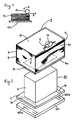
- FIG. 2 shows how the known apparatus is converted to operate with a cartridge in accordance with the invention.
- an adaptor 20 is provided which comprises a flat rectangular platform 1 having an upwardly projecting rectangular block 2 at its centre.
- the adaptor 20 is attached to the elevating paper tray 100, for example, by means of complementary magnetic strips 1a, 1b; 100a, 100b disposed on the underside of the platform 1 and the upper side of the tray 100 respectively.
- the tray 100 itself is made of a material which is itself magnetic, e.g. steel, the magnetic strips thereon can be dispensed with.
- there are many different ways of fixing the adaptor 20 to the tray 100 for example by screwing, riveting or glueing.
- the advantage of the adaptor is that it enables an existing apparatus having a conventional flat elevating support tray 100 to be converted quickly and easily by the operator without the need for a retrofit by a skilled engineer. Also, the adaptor can easily be removed or replaced by the operator for different applications. Alternatively, however the projecting member may be designed into the original apparatus in which case the projecting member may be provided as an integral part of the elevating paper tray.
- the cartridge 3 holding the stack of sheets 5 to be fed.
- the cartridge 3 comprises a generally enclosed rectangular container 4 made, for example, of paper board or plastics material.
- the walls of the container 4 are shown to be transparent so the contents can readily been seen.
- a rectangular aperture 7 slightly larger than the block 2.
- a rigid, rectangular plate 8 covering the aperture 7.
- the plate which may be made of, for example, paper board is loose and, being slightly smaller than the container 4, is slidable vertically therein.
- the stack of sheets 5 to be fed is disposed on the plate 8.
- the lateral dimensions of the container are such that the stack of sheets fits loosely therein and the depth of the container 4 is chosen to accommodate the desired number of sheets, typically 500 or 1000.
- the top face 6b of the container 4 has a concave cutaway portion 9 at the front edge, exposing the top sheet of the stack.
- the top-sheet feed roll 10 can thus bear against the top sheet and as the feed roll 10 is rotatably driven the top sheet is fed out through an elongate aperture 11 at the top edge of the front face 6c of the container 4, the aperture 11 extending substantially the full width of the front face 6c.
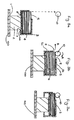
- the support tray 100 is lowered automatically (as in the known apparatus) to a base position well below the level of the feed roll 10 as shown in Figure 3a.
- the operator then takes the cartridge 3 filled, or partially filled, with the stack of sheets 5 to be fed, and locates the aperture 7 in the bottom face 6a of the container 4 over the projecting block 2 so that the block 2 bears against the underside of the plate 8 inside the container 4.
- the tray 100 is then raised automatically (again as in the known apparatus) until the top-sheet feed roll 10 engages the top sheet of the stack 5 through the aperture 9 in the top face 6b of the cartridge container 4, see Figure 3b.
- FIG. 3c shows the situation when about half of the sheets have already been fed from the stack and the tray 100 has been raised automatically to compensate so as to keep the top sheet in contact with the feed roll 10.
- the tray will continue rising automatically until the last sheet in the stack has been fed, whereupon it may be lowered automatically back to the base position for the operator to reload a fresh cartridge.
- the height of the block 2 must be approximately the same as (or greater than) the depth of the container 4 in order to ensure that the bottom sheets of the stack will be pushed up as far as the feed roll 10.
- the tray 100 Before the entire stackof sheets has been used up the tray 100 may be lowered at the operator's instigation, e.g. by pushing a control button or opening a cover door in known manner. Thus a cartridge can be removed before it is empty and changed for a different cartridge containing different sheet material, e.g. different coloured paper.
- the newly inserted cartridge may contain a part-used stack of sheets in which case Figure 3c represents the situation immediately after the cartridge has been inserted and the tray 100 has been raised automatically until the top sheet of the part-used stack engages the feed roll 10. As before the tray 100 will continue to rise automatically thereafter to keep the top sheet in operative contact with the feed roll 10 until all the sheets have been fed or until the operator wishes to change the cartridge again.
- the aperture in the top face of the container may be rectangular rather than concave, and may extend the full width of the cartridge.
- the projecting member may comprise, instead of a relatively large central block, an array of, for example five pillars, four being located at the corners of a rectangle and one at the centre thereof.
- the opening in the bottom face of the container may remain as a single rectangular aperture, but large enough to accommodate all the pillars, or alternatively there may be five individual apertures complementing the five pillars.
Description
- This invention relates to a sheet feed apparatus, particularly but not exclusively for use in a xerographic or like copier, comprising a support tray for a stack of sheets to be fed, and means for feeding the top sheet of the stack, wherein the tray is elevated automatically to maintain the top sheet of the stack in operative contact with the sheet feed means.
- Sheet feeders with automatically elevating support trays are well known and are used particularly in high performance commercial copiers where high capacity trays are required. For example, in the Xerox 9700 and 1050 machines the main copy sheet supply tray in both cases is of this automatic elevator type. The operator places a loose stack of sheets on the tray by hand. Then when an appropriate signal is given, e.g. by pressing a control button or closing a cover door, the tray is raised automatically until the top sheet of the stack is brought into operative contact with the feed mechanism. As the sheets are fed from the top of the stack into the processing portion of the copier during use, the height of the stack reduces and as it does so, the tray is elevated automatically to keep the top sheet of the stack in contact with the feed mechanism. To replace or change the stack of copy sheets at any time the support tray is automatically lowered to a base position in response to an appropriate signal, for example when the cover door is opened or when the operator presses an appropriate control button.
- In some circumstances it may be desirable to change the stack of copy sheets quite frequently. For example, particularly in a "copy centre" environment, there will be a need to run a whole variety of different throughput materials such as various weights and colours of paper, card stock, pre-punched paper, envelopes, labels, transparencies for overhead projectors, drawing film, and customised pre-printed materials like letter headed paper.
- Each time a different throughput material is used the stack has to be physically handled by the operator first as it is inserted into the machine and subsequently as it is removed to make way for a stack of different material. During handling and also during storage the loose stacks of different sheets are vulnerable to contamination and damage which are detrimental to copy quality, high performance machines especially being sensitive to the surface characteristics of the copy sheets, their moisture content, and also to any debris present on the surface of the sheets.
- US-A-4 504 053 discloses a sheet feed apparatus of a different type, comprising a fixed base table rather than an elevating support tray. A sheet containing bin is located on the base table. A lift is located at the centre of the base table and is arranged to rise through an opening therein. The bin, which has a completely open top face, also has an opening in its bottom face through which the lift moves to engage a pallet supporting a stack of sheets within the bin thus raising the stack to a top-sheet feeding apparatus, the bin being locked automatically to the base table when the lift is operational.
- Yet another type of sheet feed apparatus, which also does not have an elevating support tray, is disclosed in FR-A-2 019 154. In that apparatus, a stack of sheets is supported on a receiving plate which, during operation of the apparatus, remains stationary. The sheet feed means comprises a roller supported on a rocking arm so that, as sheets are fed from the stack, the roller can move downwards to remain in operative engagement with the top of the stack.
- According to the present invention, a sheet feed apparatus having the features specified in the opening paragraph is characterised in that at least one upwardly projecting member is present on the tray in fixed relation therewith, and in that the stack of sheets is provided on the tray in a cartridge having in its bottom face adjacent the support tray an opening permitting entry of said projecting member, the cartridge containing vertically movable plate for supporting the stack of sheets and extending over the opening in the bottom face thereby in operation the projecting member on the elevating tray bears against the underside of the plate so that the plate and the stack of sheets supported thereon are raised to bring the top sheet of the stack into operative contact with the feed means.
- Preferably the shape of the opening in the bottom face of the cartridge is complementary to the shape of the projecting member, thereby providing a locating feature for the cartridge on the tray.
- In one embodiment the cartridge comprises a generally enclosed rectangular container for holding the stack of sheets, the container having a first opening in the top face for exposing a portion of the top sheet to permit the sheet feed means to engage said top sheet, and a second opening in a side face and extending to the top edge of said side face, through which second opening sheets can be fed from the top of the stack. In operation, the top sheet of the stack is brought into contact with the top face of the container thereby raising the container until the top sheet of the stack is brought into operative contact with the sheet feed means.
- The use of this cartridge to hold the stack of sheets not only simplifies change over of throughput material, but also means that the individual sheets are less likely to be damaged or contaminated because the operator does not actually touch the stack when it is being loaded into and out of the sheet feed apparatus. The cartridge also provides a convenient means of storing either full or part-used stacks of sheets, its generally enclosed construction helping to protect the contents from the environment without the need for a separate protective storage box.
- In apparatus in accordance with the invention, the at least one upwardly projecting member may be removably mounted on the supporting tray. The apparatus may, for example, include means for attaching the projecting member(s) to the upper side of the support tray, to removably mount the projecting member in fixed relationship with the support tray. In that way, a conventional sheet feed apparatus having an automatically elevating stack support tray can be converted quickly and easily to operate with a cartridge instead of a loose stack of sheets.
- An embodiment of the invention will now be described by way of example with reference to the accompanying drawings in which:-
- Figure 1 is a schematic sectional view of a known sheet feed apparatus of the automatic elevator type,
- Figure 2 is a schematic perspective view of a sheet feed apparatus employing a cartridge for holding the sheets to be fed in accordance with the invention, and
- Figures 3a to 3c are schematic sectional views of the sheet feed apparatus in Figure 1 at various stages during operation.
- For comparative purposes there is shown schematically in Fig. 1 a known sheet feed apparatus of the type used in the main paper supply tray of commercially available xerographic machines such as the Xerox 9700 and 1050. The apparatus comprises a
horizontal support tray 100 on which is located a loose stack ofsheets 5 to be fed. The sheets may be retained by lateral guide members not shown in the Figure. Thesupport tray 100 is driven and controlled in such a manner that it rises automatically to keep the top sheet of the stack in operative contact with a top-sheet feed roll 10 so that when theroll 10 is driven in the direction of arrow A the top sheet is fed from the stack in the direction of arrow B into the copier. - Figure 2 shows how the known apparatus is converted to operate with a cartridge in accordance with the invention. For this purpose an adaptor 20 is provided which comprises a flat
rectangular platform 1 having an upwardly projectingrectangular block 2 at its centre. The adaptor 20 is attached to the elevatingpaper tray 100, for example, by means of complementarymagnetic strips 1a, 1b; 100a, 100b disposed on the underside of theplatform 1 and the upper side of thetray 100 respectively. If, however, thetray 100 itself is made of a material which is itself magnetic, e.g. steel, the magnetic strips thereon can be dispensed with. Needless to say there are many different ways of fixing the adaptor 20 to thetray 100, for example by screwing, riveting or glueing. The advantage of the adaptor is that it enables an existing apparatus having a conventional flat elevating support tray 100 to be converted quickly and easily by the operator without the need for a retrofit by a skilled engineer. Also, the adaptor can easily be removed or replaced by the operator for different applications. Alternatively, however the projecting member may be designed into the original apparatus in which case the projecting member may be provided as an integral part of the elevating paper tray. - Above the
block 2 is present acartridge 3 holding the stack ofsheets 5 to be fed. Thecartridge 3 comprises a generally enclosedrectangular container 4 made, for example, of paper board or plastics material. In Figure 2 the walls of thecontainer 4 are shown to be transparent so the contents can readily been seen. In the bottom face 6a of thecontainer 4 at the centre is a rectangular aperture 7 slightly larger than theblock 2. - Inside the
container 4, adjacent the bottom face 6a is a rigid,rectangular plate 8 covering the aperture 7. The plate which may be made of, for example, paper board is loose and, being slightly smaller than thecontainer 4, is slidable vertically therein. The stack ofsheets 5 to be fed is disposed on theplate 8. The lateral dimensions of the container are such that the stack of sheets fits loosely therein and the depth of thecontainer 4 is chosen to accommodate the desired number of sheets, typically 500 or 1000. Thetop face 6b of thecontainer 4 has a concavecutaway portion 9 at the front edge, exposing the top sheet of the stack. The top-sheet feed roll 10 can thus bear against the top sheet and as thefeed roll 10 is rotatably driven the top sheet is fed out through anelongate aperture 11 at the top edge of the front face 6c of thecontainer 4, theaperture 11 extending substantially the full width of the front face 6c. - The manner in which the apparatus operates with a cartridge as described above will now be described with references to Figures 3a to 3c.
- In order to insert or change a
cartridge 3 thesupport tray 100 is lowered automatically (as in the known apparatus) to a base position well below the level of thefeed roll 10 as shown in Figure 3a. The operator then takes thecartridge 3 filled, or partially filled, with the stack ofsheets 5 to be fed, and locates the aperture 7 in the bottom face 6a of thecontainer 4 over the projectingblock 2 so that theblock 2 bears against the underside of theplate 8 inside thecontainer 4. Thetray 100 is then raised automatically (again as in the known apparatus) until the top-sheet feed roll 10 engages the top sheet of thestack 5 through theaperture 9 in thetop face 6b of thecartridge container 4, see Figure 3b. As thefeed roll 10 is driven in the direction of arrow A the top sheet is fed from the stack out through theelongate aperture 11 in the front face 6c of thecontainer 4 in the direction of arrow B into the copier. Figure 3c shows the situation when about half of the sheets have already been fed from the stack and thetray 100 has been raised automatically to compensate so as to keep the top sheet in contact with thefeed roll 10. The tray will continue rising automatically until the last sheet in the stack has been fed, whereupon it may be lowered automatically back to the base position for the operator to reload a fresh cartridge. It will be evident from the foregoing that the height of theblock 2 must be approximately the same as (or greater than) the depth of thecontainer 4 in order to ensure that the bottom sheets of the stack will be pushed up as far as thefeed roll 10. - Before the entire stackof sheets has been used up the
tray 100 may be lowered at the operator's instigation, e.g. by pushing a control button or opening a cover door in known manner. Thus a cartridge can be removed before it is empty and changed for a different cartridge containing different sheet material, e.g. different coloured paper. Of course the newly inserted cartridge may contain a part-used stack of sheets in which case Figure 3c represents the situation immediately after the cartridge has been inserted and thetray 100 has been raised automatically until the top sheet of the part-used stack engages thefeed roll 10. As before thetray 100 will continue to rise automatically thereafter to keep the top sheet in operative contact with thefeed roll 10 until all the sheets have been fed or until the operator wishes to change the cartridge again. - It will be evident to a person skilled in the art that various modifications may be made within the scope of the present invention. For example, the aperture in the top face of the container may be rectangular rather than concave, and may extend the full width of the cartridge. Also, the projecting member may comprise, instead of a relatively large central block, an array of, for example five pillars, four being located at the corners of a rectangle and one at the centre thereof. In this case, the opening in the bottom face of the container may remain as a single rectangular aperture, but large enough to accommodate all the pillars, or alternatively there may be five individual apertures complementing the five pillars.
Claims (5)
- A sheet feed apparatus comprising a support tray (100) for a stack of sheets to be fed, and means (10) for feeding the top sheet of the stack, wherein said tray is elevated automatically to maintain the top sheet of the stack in operative contact with the sheet feed means, characterised in that
at least one upwardly projecting member (2) is present on the tray in fixed relationship therewith, and in that the stack of sheets (5) is provided in a cartridge (3) having in its bottom face (6a) adjacent the support tray an opening (7) permitting entry of said projecting member,
the cartridge containing a vertically movable plate (8) for supporting the stack of sheets and extending over the opening in the bottom face whereby in operation the projecting member on the elevating tray bears against the underside of the plate so that the plate and the stack of sheets supported thereon are raised to bring the top sheet of the stack into operative contact with the feed means. - A sheet feed apparatus as claimed in claim 1, wherein the shape of the opening in the bottom face of the cartridge is complementary to the shape of the projecting member, thereby providing locating means for the cartridge.
- A sheet feed apparatus as claimed in claim 1 or claim 2, wherein
the cartridge comprises a generally enclosed rectangular container for holding the stack of sheets, the container having
a first opening (9) in the top face (6b) for exposing a portion of the top sheet to permit the sheet feed means to engage said top sheet, and
a second opening (11) in a side face (6c) and extending to the top edge of said side face, through which second opening sheets can be fed from the top of the stack,
whereby in operation the top sheet of the stack is brought into contact with the top face of the container thereby raising the container until the top sheet of the stack is brought into operative contact with the sheet feed means. - A sheet feed apparatus as claimed in any one of the preceding claims, in which the at least one upwardly projecting member is removably mounted on the support tray.
- A sheet feed apparatus as claimed in any one of the preceding claims, including means (1a, 100a; 1b, 100b) for attaching said projecting member(s) to the upper side of the support tray, to removably mount the projecting member in fixed relationship with the support tray.
Applications Claiming Priority (2)
| Application Number | Priority Date | Filing Date | Title |
|---|---|---|---|
| GB868611792A GB8611792D0 (en) | 1986-05-14 | 1986-05-14 | Sheet feed apparatus & cartridge |
| GB8611792 | 1986-05-14 |
Publications (3)
| Publication Number | Publication Date |
|---|---|
| EP0246067A2 EP0246067A2 (en) | 1987-11-19 |
| EP0246067A3 EP0246067A3 (en) | 1988-06-01 |
| EP0246067B1 true EP0246067B1 (en) | 1993-02-10 |
Family
ID=10597879
Family Applications (1)
| Application Number | Title | Priority Date | Filing Date |
|---|---|---|---|
| EP87304206A Expired - Lifetime EP0246067B1 (en) | 1986-05-14 | 1987-05-12 | Sheet feed apparatus and cartridge therefor |
Country Status (5)
| Country | Link |
|---|---|
| US (1) | US4830354A (en) |
| EP (1) | EP0246067B1 (en) |
| JP (1) | JPH07115761B2 (en) |
| DE (1) | DE3784096T2 (en) |
| GB (1) | GB8611792D0 (en) |
Families Citing this family (13)
| Publication number | Priority date | Publication date | Assignee | Title |
|---|---|---|---|---|
| US5106074A (en) * | 1989-12-28 | 1992-04-21 | Brother Kogyo Kabushiki Kaisha | Sheet supplying apparatus having sheet storing cassette |
| DE19581661C2 (en) | 1994-09-22 | 1998-11-26 | Advantest Corp | Ic receiving cup storage device and mounting device for this |
| US5940116A (en) * | 1996-02-13 | 1999-08-17 | Samsung Electronics Co., Ltd. | Device for connecting an option tray of a laser beam printer simultaneously with the placement thereof |
| JP3756331B2 (en) * | 1998-10-23 | 2006-03-15 | 富士写真フイルム株式会社 | Recording paper package |
| US6932527B2 (en) * | 1999-01-25 | 2005-08-23 | Fargo Electronics, Inc. | Card cartridge |
| US6286827B1 (en) * | 1999-11-18 | 2001-09-11 | Xerox Corporation | High capacity automatic sheet input system for a reproduction apparatus |
| US6758616B2 (en) * | 2000-01-21 | 2004-07-06 | Fargo Electronics, Inc. | Identification card printer |
| US6398210B1 (en) * | 2000-11-22 | 2002-06-04 | Toshiba Tec Kabushiki Kaisha | Sheet cartridge and sheet feeding apparatus |
| US6945527B2 (en) * | 2003-02-28 | 2005-09-20 | Hewlett-Packard Development Company, L.P. | High capacity media apparatus and method |
| US7093737B2 (en) * | 2003-04-16 | 2006-08-22 | Kimberly-Clark Worldwide, Inc. | Container and cartridge for dispensing paper products |
| US7124911B2 (en) * | 2003-04-16 | 2006-10-24 | Kimberly-Clark Worldwide, Inc. | Container and cartridge for dispensing paper products |
| US7568850B2 (en) * | 2004-08-18 | 2009-08-04 | Hewlett-Packard Development Company, L.P. | Media stack control |
| JP2006256705A (en) * | 2005-03-15 | 2006-09-28 | Pfu Ltd | Hopper unit |
Family Cites Families (23)
| Publication number | Priority date | Publication date | Assignee | Title |
|---|---|---|---|---|
| US2391125A (en) * | 1942-05-25 | 1945-12-18 | Charles H Carpenter | Commodity conveying apparatus |
| DE1230042B (en) * | 1965-06-29 | 1966-12-08 | Siemens Ag | Stack lifting device |
| US3635468A (en) * | 1968-09-30 | 1972-01-18 | Ricoh Kk | Sheet container and feeding device |
| JPS4926847B1 (en) * | 1969-10-22 | 1974-07-12 | ||
| US3767188A (en) * | 1971-05-24 | 1973-10-23 | Burt & Co F N | Paper feeding device |
| US3919972A (en) * | 1971-06-04 | 1975-11-18 | Canon Kk | Automatic cut sheet feeding unit |
| US4219192A (en) * | 1978-01-03 | 1980-08-26 | Pitney Bowes Inc. | Sheet loading and storing assembly |
| CA1104599A (en) * | 1978-04-20 | 1981-07-07 | Benzion Landa | Large capacity combination magazine and sheet feeder for copying machines |
| GB2038289B (en) * | 1978-12-29 | 1983-05-05 | Ricoh Kk | Sheet separating apparatus |
| GB2041886B (en) * | 1979-02-08 | 1983-01-26 | Simon Container Mach Ltd | Stack elevating device |
| US4248525A (en) * | 1979-05-03 | 1981-02-03 | Eastman Kodak Company | Apparatus for producing sets of collated copies |
| JPS5815393Y2 (en) * | 1979-05-31 | 1983-03-28 | コニカ株式会社 | Copy paper supply cassette |
| JPS56114957A (en) * | 1980-02-18 | 1981-09-09 | Canon Inc | Transfer material feeder |
| JPS5774344U (en) * | 1980-10-24 | 1982-05-08 | ||
| US4504053A (en) * | 1981-02-19 | 1985-03-12 | Konishiroku Photo Industry Co., Ltd. | Paper feeding means for recording apparatus |
| GB2120214B (en) * | 1982-05-14 | 1986-08-28 | Bell Printers Limited Peter | Dispenser for sheets or forms |
| JPS5939631A (en) * | 1982-08-31 | 1984-03-05 | Konishiroku Photo Ind Co Ltd | Universal paper feed cassette |
| CA1235503A (en) * | 1982-09-06 | 1988-04-19 | John N. Dent | Label handling apparatus |
| JPS59138541A (en) * | 1983-01-28 | 1984-08-09 | Canon Inc | Sheet stacking device |
| JPS59190128A (en) * | 1983-04-12 | 1984-10-27 | Mita Ind Co Ltd | Paper feed device of copying machine and paper feed cassette used for copying machine |
| US4555105A (en) * | 1983-04-15 | 1985-11-26 | At&T Technologies, Inc. | Method and apparatus utilizing magnetically coupled rollers to feed sheets |
| GB2141406A (en) * | 1983-06-13 | 1984-12-19 | Inoventors Ltd | Dispensers for stacks of sheets |
| JPH112540A (en) * | 1997-06-13 | 1999-01-06 | Matsushita Electric Ind Co Ltd | Route retrieval device |
-
1986
- 1986-05-14 GB GB868611792A patent/GB8611792D0/en active Pending
-
1987
- 1987-05-11 US US07/048,160 patent/US4830354A/en not_active Expired - Fee Related
- 1987-05-12 DE DE8787304206T patent/DE3784096T2/en not_active Expired - Fee Related
- 1987-05-12 EP EP87304206A patent/EP0246067B1/en not_active Expired - Lifetime
- 1987-05-13 JP JP62116706A patent/JPH07115761B2/en not_active Expired - Lifetime
Also Published As
| Publication number | Publication date |
|---|---|
| DE3784096T2 (en) | 1993-06-24 |
| JPS62275934A (en) | 1987-11-30 |
| EP0246067A3 (en) | 1988-06-01 |
| GB8611792D0 (en) | 1986-06-25 |
| JPH07115761B2 (en) | 1995-12-13 |
| EP0246067A2 (en) | 1987-11-19 |
| DE3784096D1 (en) | 1993-03-25 |
| US4830354A (en) | 1989-05-16 |
Similar Documents
| Publication | Publication Date | Title |
|---|---|---|
| EP0246067B1 (en) | Sheet feed apparatus and cartridge therefor | |
| US3919972A (en) | Automatic cut sheet feeding unit | |
| KR100226091B1 (en) | Manual sheet feeding device | |
| EP1101718B1 (en) | High capacity automatic sheet input system for a reproduction apparatus | |
| EP0601734B1 (en) | High capacity dual tray variable sheet size sheet feeder | |
| US4765605A (en) | Paper cassette tray with front edge positioning cams | |
| US4579328A (en) | Copy paper feeding device for electrophotographic copying machine | |
| US3635468A (en) | Sheet container and feeding device | |
| US4478401A (en) | Apparatus for feeding sheets | |
| US5328167A (en) | Sheet feed apparatus | |
| JP2774676B2 (en) | Image forming device | |
| KR100226018B1 (en) | Printer | |
| US5338021A (en) | Paper feeding mechanism | |
| US20060244208A1 (en) | Sheet discharge tray and a multiple bin sorter equipped with the same | |
| US4982945A (en) | Plural mode document restacking tray for a copier document handler | |
| US4946157A (en) | Sheet loading and unloading mechanism | |
| US5207413A (en) | Vacuum sheet film transport and method | |
| JP2774670B2 (en) | Paper feeder for printing press | |
| KR20010052700A (en) | Tray for narrow and normal width sheets | |
| JPS6150859B2 (en) | ||
| JPH042512B2 (en) | ||
| JPH0339933B2 (en) | ||
| JPS6016579Y2 (en) | feeding cassette | |
| JP3224470B2 (en) | Sheet loading device and image forming device | |
| JPH0420839Y2 (en) |
Legal Events
| Date | Code | Title | Description |
|---|---|---|---|
| PUAI | Public reference made under article 153(3) epc to a published international application that has entered the european phase |
Free format text: ORIGINAL CODE: 0009012 |
|
| AK | Designated contracting states |
Kind code of ref document: A2 Designated state(s): DE FR GB IT SE |
|
| PUAL | Search report despatched |
Free format text: ORIGINAL CODE: 0009013 |
|
| AK | Designated contracting states |
Kind code of ref document: A3 Designated state(s): DE FR GB IT SE |
|
| 17P | Request for examination filed |
Effective date: 19881201 |
|
| 17Q | First examination report despatched |
Effective date: 19910517 |
|
| GRAA | (expected) grant |
Free format text: ORIGINAL CODE: 0009210 |
|
| AK | Designated contracting states |
Kind code of ref document: B1 Designated state(s): DE FR GB IT SE |
|
| ET | Fr: translation filed | ||
| REF | Corresponds to: |
Ref document number: 3784096 Country of ref document: DE Date of ref document: 19930325 |
|
| ITF | It: translation for a ep patent filed |
Owner name: MODIANO & ASSOCIATI S.R.L. |
|
| PLBE | No opposition filed within time limit |
Free format text: ORIGINAL CODE: 0009261 |
|
| STAA | Information on the status of an ep patent application or granted ep patent |
Free format text: STATUS: NO OPPOSITION FILED WITHIN TIME LIMIT |
|
| 26N | No opposition filed | ||
| EAL | Se: european patent in force in sweden |
Ref document number: 87304206.3 |
|
| PGFP | Annual fee paid to national office [announced via postgrant information from national office to epo] |
Ref country code: SE Payment date: 19950214 Year of fee payment: 9 |
|
| PGFP | Annual fee paid to national office [announced via postgrant information from national office to epo] |
Ref country code: GB Payment date: 19950501 Year of fee payment: 9 |
|
| PGFP | Annual fee paid to national office [announced via postgrant information from national office to epo] |
Ref country code: FR Payment date: 19950510 Year of fee payment: 9 |
|
| PGFP | Annual fee paid to national office [announced via postgrant information from national office to epo] |
Ref country code: DE Payment date: 19950511 Year of fee payment: 9 |
|
| PG25 | Lapsed in a contracting state [announced via postgrant information from national office to epo] |
Ref country code: GB Effective date: 19960512 |
|
| PG25 | Lapsed in a contracting state [announced via postgrant information from national office to epo] |
Ref country code: SE Effective date: 19960513 |
|
| GBPC | Gb: european patent ceased through non-payment of renewal fee |
Effective date: 19960512 |
|
| PG25 | Lapsed in a contracting state [announced via postgrant information from national office to epo] |
Ref country code: FR Effective date: 19970131 |
|
| PG25 | Lapsed in a contracting state [announced via postgrant information from national office to epo] |
Ref country code: DE Effective date: 19970201 |
|
| EUG | Se: european patent has lapsed |
Ref document number: 87304206.3 |
|
| REG | Reference to a national code |
Ref country code: FR Ref legal event code: ST |
|
| PG25 | Lapsed in a contracting state [announced via postgrant information from national office to epo] |
Ref country code: IT Free format text: LAPSE BECAUSE OF NON-PAYMENT OF DUE FEES;WARNING: LAPSES OF ITALIAN PATENTS WITH EFFECTIVE DATE BEFORE 2007 MAY HAVE OCCURRED AT ANY TIME BEFORE 2007. THE CORRECT EFFECTIVE DATE MAY BE DIFFERENT FROM THE ONE RECORDED. Effective date: 20050512 |