EP0248090A1 - Aperiodic generator - Google Patents
Aperiodic generator Download PDFInfo
- Publication number
- EP0248090A1 EP0248090A1 EP85400465A EP85400465A EP0248090A1 EP 0248090 A1 EP0248090 A1 EP 0248090A1 EP 85400465 A EP85400465 A EP 85400465A EP 85400465 A EP85400465 A EP 85400465A EP 0248090 A1 EP0248090 A1 EP 0248090A1
- Authority
- EP
- European Patent Office
- Prior art keywords
- transformer
- aperiodic
- adaptation
- generators
- autotransformer
- Prior art date
- Legal status (The legal status is an assumption and is not a legal conclusion. Google has not performed a legal analysis and makes no representation as to the accuracy of the status listed.)
- Withdrawn
Links
Images
Classifications
-
- H—ELECTRICITY
- H05—ELECTRIC TECHNIQUES NOT OTHERWISE PROVIDED FOR
- H05B—ELECTRIC HEATING; ELECTRIC LIGHT SOURCES NOT OTHERWISE PROVIDED FOR; CIRCUIT ARRANGEMENTS FOR ELECTRIC LIGHT SOURCES, IN GENERAL
- H05B6/00—Heating by electric, magnetic or electromagnetic fields
- H05B6/02—Induction heating
- H05B6/04—Sources of current
Definitions
- the present invention relates to an improvement made to induction heating generators, called “aperiodic generators”.
- generators constructed according to this technique there is in the generator itself an adaptation transformer of the aperiodic transformer carrying mainly active energy and whose object is to adapt the operating impedance of the electronic tube used in these generators to the power line.
- these transformers consist of a primary and a secondary or of several primary windings and of multiple secondary; these are always identical and interconnected.
- the transformation ratios usually used are between 5 and 7.
- the frequency of these generators is usually between 50 and 300 KHz, it is necessary to use materials with low dielectric losses for cable insulation.
- the multi-conductor cables used for the transport of energy are usually insulated with polyethylene and are the subject of special projects.
- the practical operating voltages used on induction generators are usually between 300 and 500 volts; these voltages being determined by the limit voltages of the capacitor banks usable for low-voltage induction heating.
- This transformer usually has intermediate sockets allowing the voltage to be adjusted to plus or minus 20% around the ratio of the matching transformer located at the end of the cable.
- the object of the present invention is to obtain directly from the aperiodic transformer the practical operating voltages between 300 and 500 volts.
- the aperiodic transformer described above each of the secondary and divided into two separate half aecondaries. tincts each connected to an energy transport cable.
- these cables can be connected either in series or in parallel so as to obtain exactly the same possibilities as in the case described above.
- the present invention further simplifies both the production of the aperiodic transformers and the adapter boxes.
- the invention consists in making an aperiodic transformer comprising at least one primary winding connected in alternation between the anode of the tube and the cathode and one or more secondary comprising at least three sockets; these three sockets being, one the reference potential, the second the minimum operating voltage, the third the operating voltage.
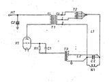
- the tube VI is connected to the aperiodic transformer Tl where the primary winding is represented at El and the secondary winding E2.
- the taps 1 and 2 of this winding are connected to an auxiliary autotransformer T2 intended to carry out a voltage division in order to adapt the generator to its load.
- the energy transport line L1 connects this device to the adaptation box, the composition of which is limited to a battery of capacitors CI associated with the inductor N1. 1
- a second line L2 brings the voltage drawn across the oscillating circuit CI-NI to the excitation autotransformer T3.
- the resistance RI is the gate self-polarization resistance which is associated with the decoupling capacitor Cl; C2 is the decoupling capacitor of the anode voltage.
- Such a device makes it possible to limit the adaptation box to the single capacitor bank; all the adaptation and excitation transformers found in the generator and no longer as previously in the adaptation box.
- the transformer T2 is no longer necessary because it can be provided directly on the secondary of the aperiodic transformer, the number of sockets allowing the desired adaptation.
- the generator is connected to several adaptation boxes, it is possible to provide switching by contactor, as in the known embodiments, but the same excitation transformers T3 and adaptation T2 are used independently of the number of cabinets while in known embodiments each adapter cabinet required an autotransformer and a separate grid transformer.
Abstract
Description
La présente invention a pour objet un perfectionnement apporté aux générateurs de chauffage par induction, dits "générateurs apériodiques".The present invention relates to an improvement made to induction heating generators, called "aperiodic generators".
Dans les générateurs contruits selon cette technique, on dispose dans le générateur proprement dit d'un transformateur d'adaptation du transformateur apériodique véhiculant principalement de l'énergie active et dont l'objet est d'adapter l'impédance de fonctionnement du tube électronique utilisé dans ces générateurs à la ligne de transport d'énergie. Dans la pratique, ces transformateurs sont constitués d'un primaire et d'un secondaire ou de plusieurs enroulements primaires et de secondaires multiples ; ces derniers sont toujours identiques et reliés entre eux. Les rapports de transformation habituellement utilisés sont situés entre 5 et 7.In generators constructed according to this technique, there is in the generator itself an adaptation transformer of the aperiodic transformer carrying mainly active energy and whose object is to adapt the operating impedance of the electronic tube used in these generators to the power line. In practice, these transformers consist of a primary and a secondary or of several primary windings and of multiple secondary; these are always identical and interconnected. The transformation ratios usually used are between 5 and 7.
La conséquence de cette façon de faire est de situer la tension appliquée au cable de transport d'énergie à des valeurs comprises entre 500 et 1200 volts, selon les rapports de transformation utilisés ainsi que selon les tensions appliquées au tube électronique de ces générateurs.The consequence of this way of doing things is to locate the voltage applied to the energy transport cable at values between 500 and 1200 volts, according to the transformation ratios used as well as according to the voltages applied to the electronic tube of these generators.
A titre d'exemple pratique, pour un générateur utilisant une tension de fonctionnement de 8000 volts, et un rapport de transformation de 6, la tension efficace fournie par la lampe serait de 8000 s 2 soit 5660 volts, ce qui amène au secondaire du transformateur et, par conséquent, sur le cable de transport d'énergie une tension'de 5660 s 6 = 943 volts.As a practical example, for a generator using an operating voltage of 8000 volts, and a transformation ratio of 6, the effective voltage supplied by the lamp would be 8000
Comme la fréquence de ces générateurs se situe habituellement entre 50 et 300 KHz, il est nécessaire d'employer pour l'isolation du cable des matériaux présentant des pertes diélectriques faibles.
Les cables multi conducteurs utilisés pour le transport d'énergie sont habituellement isolés à l'aide de polyéthylène et font l'objet de réalisations spéciales.As the frequency of these generators is usually between 50 and 300 KHz, it is necessary to use materials with low dielectric losses for cable insulation.
The multi-conductor cables used for the transport of energy are usually insulated with polyethylene and are the subject of special projects.
En outre, les tensions d'utilisation pratiques utilisées sur les générateurs à induction sont habituellement comprises entre 300 et 500 volts; ces tensions étant déterminées par les tensions limites des batteries de condensateurs utilisables pour le chauffage par induction en basse tension.In addition, the practical operating voltages used on induction generators are usually between 300 and 500 volts; these voltages being determined by the limit voltages of the capacitor banks usable for low-voltage induction heating.
On est donc amenés dans la pratique à disposer d'un deuxième transformateur habituellement situé à l'extrémité du cable, et qui divise la tension par deux. Ce transformateur comporte habituellement des prises intermédiaires permettant d'ajuster la tension à plus ou moins 20 % autour du rapport du transformateur d'adaptation situé à l'extrémité du cable.We are therefore led in practice to have a second transformer usually located at the end of the cable, and which divides the voltage by two. This transformer usually has intermediate sockets allowing the voltage to be adjusted to plus or minus 20% around the ratio of the matching transformer located at the end of the cable.
L'objet de la présente invention est d'obtenir directement depuis le transformateur apériodique les tensions pratiques d'utilisation comprises entre 300 et 500 volts. A cet effet, sur le transformateur apériodique décrit précédemment chacun des secondaires et divisé en deux demi aecondaires distincts.
tincts reliés chacun à un cable de transport d'énérgie.The object of the present invention is to obtain directly from the aperiodic transformer the practical operating voltages between 300 and 500 volts. For this purpose, on the aperiodic transformer described above each of the secondary and divided into two separate half aecondaries.
tincts each connected to an energy transport cable.
La tension de transport de l'énergie n'a glus que la moitié de ce qu'elle était précédemment. Les pertes diélectriques sont divisées par quatre et il est plus nécessaire d'utiliser dés cables spéciaux.The voltage of energy transport has glued only half of what it was previously. Dielectric losses are divided by four and it is no longer necessary to use special cables.
A l'exptrémité de ces cables, côté utilisation, ces cables peuvent être reliés soit en série, soit en parallèle de façon à obtenir exactement les mêmes possibilités que dans le cas précédemment décrit. On peut ajouter, toujours du côté utilisation, un transformateur ou un autotransformateur d'adaptation complémentaire permettant un ajustage de la tension à plus ou moins 20 % de la puissance au maximum et peut être réduit dans un volume de 1 à 4 environ par rapport à la réalisation précédemment décrite.At the end of these cables, on the use side, these cables can be connected either in series or in parallel so as to obtain exactly the same possibilities as in the case described above. One can add, always on the use side, a transformer or an autotransformer of complementary adaptation allowing an adjustment of the tension to more or less 20% of the power to the maximum and can be reduced in a volume from 1 to 4 approximately compared to the embodiment previously described.
Il est ainsi possible de fabriquer des coffrets d'adaptation dont le volume est lui-même dans un rapport de 1 à 4 par rapport aux réalisations antérieures. Il en résulte parallèlement une réduction du coût et une amélioration de conditions d'utilisation puisque il est souhaitable de donner à l'utilisateur un coffret d'adaptation de dimension et de poids aussi réduit que possible.It is thus possible to manufacture adaptation boxes whose volume is itself in a ratio of 1 to 4 compared to previous embodiments. At the same time, this results in a reduction in cost and an improvement in conditions of use since it is desirable to give the user an adaptation box of dimension and weight as reduced as possible.
Dans le brevet d'invention auquel le présent certificat se réfère, il est prévu d'utiliser 2 secondaires connectés en série ou en parallèle, dans le but de simplifier la réalisation des coffrets d'adaptation destinés au générateur dit "générateur apériodique".In the invention patent to which this certificate refers, it is planned to use 2 secondary connected in series or in parallel, in order to simplify the production of adaptation boxes for the generator called "aperiodic generator".
La présente invention permet de simplifier encore à la fois la réalisation des transformateurs apériodiques et les coffrets d'adaptation.The present invention further simplifies both the production of the aperiodic transformers and the adapter boxes.
L'invention consiste à réaliser un transformateur apériodique comportant au moins un enroulement primaire connecté en alternatif entre l'anode du tube et la cathode et un ou plusieurs secondaires comportant au moins trois prises ; ces trois prises étant, l'une le potentiel de référence, la deuxième la tension minimum d'utilisation, la troisième la tension d'utilisation.The invention consists in making an aperiodic transformer comprising at least one primary winding connected in alternation between the anode of the tube and the cathode and one or more secondary comprising at least three sockets; these three sockets being, one the reference potential, the second the minimum operating voltage, the third the operating voltage.
Il est évidemment possible de disposer de prises intermédiaires entre les deux prises en question, mais en pratique, les tensions par spire utilisées dans les transformateurs apériodiques haute fréquence étant de l'ordre de 150 V ; il apparait plus avantageux de disposer entre les prises 1 et 2 un autotransformateur distinct destiné à effectuer une adaptation fine du générateur à sa charge.It is obviously possible to have intermediate sockets between the two sockets in question, but in practice, the voltages per turn used in the high frequency aperiodic transformers being of the order of 150 V; it appears more advantageous to have between the sockets 1 and 2 a separate autotransformer intended to carry out a fine adaptation of the generator to its load.
Dans le schéma illustrant le dispositif objet de la présente invention, le tube VI est relié au transformateur apériodique Tl où l'enroulement primaire est représenté en El et l'enroulement secondaire E2.In the diagram illustrating the device which is the subject of the present invention, the tube VI is connected to the aperiodic transformer Tl where the primary winding is represented at El and the secondary winding E2.
Les prises 1 et 2 de cet enroulement sont reliées à un autotransformateur auxilliaire T2 destiné à effectuer une division de tension dans le but d'adapter le générateur à sa charge.The
La ligne de transport d'énergie Ll relie ce dispositif au coffret d'adaptation dont la composition se limite à une batterie de condensateurs CI associée à l'inducteur N1. 1The energy transport line L1 connects this device to the adaptation box, the composition of which is limited to a battery of capacitors CI associated with the inductor N1. 1
Une deuxième ligne L2 ramène la tension prélevée aux bornes du circuit oscillant CI-NI à l'autotransformateur d'excitation T3. La résistance RI est la résistance d'autopolarisation de grille qui est associée au condensateur de découplage Cl ; C2 est le condensateur de découplage de la tension d'anode.A second line L2 brings the voltage drawn across the oscillating circuit CI-NI to the excitation autotransformer T3. The resistance RI is the gate self-polarization resistance which is associated with the decoupling capacitor Cl; C2 is the decoupling capacitor of the anode voltage.
Un tel dispositif permet de limiter le coffret d'adaptation à la seule batterie de condensateurs ; l'ensemble des transformateurs d'adaptation et d'excitation se trouvant dans le générateur et non plus comme antérieurement dans le coffret d'adaptation.Such a device makes it possible to limit the adaptation box to the single capacitor bank; all the adaptation and excitation transformers found in the generator and no longer as previously in the adaptation box.
Dans le cas des générateurs moyenne fréquence ou les tensions par spire sont beaucoup plus faibles qu'en haute fréquence, (entre 30 et 60 V par spire habituellement), le transformateur T2 n'est plus nécessaire car on peut prévoir directement sur le secondaire du transformateur apériodique, le nombre de prises permettant l'adaptation souhaitée.In the case of medium frequency generators where the voltages per turn are much lower than at high frequency, (between 30 and 60 V per turn usually), the transformer T2 is no longer necessary because it can be provided directly on the secondary of the aperiodic transformer, the number of sockets allowing the desired adaptation.
Si le générateur est relié à plusieurs coffrets d'adaptation, il est possible de prévoir une commutation par contacteur, comme dans les réalisations connues, mais ce sont les mêmes transformateurs d'excitation T3 et d'adaptation T2 qui sont utilisées indépendamment du nombre de coffrets alors que dans les réalisations connues chaque coffret d'adaptation nécessitait un autotransformateur d'adaptation et un transformateur de grille distinct.If the generator is connected to several adaptation boxes, it is possible to provide switching by contactor, as in the known embodiments, but the same excitation transformers T3 and adaptation T2 are used independently of the number of cabinets while in known embodiments each adapter cabinet required an autotransformer and a separate grid transformer.
Claims (4)
Applications Claiming Priority (4)
| Application Number | Priority Date | Filing Date | Title |
|---|---|---|---|
| FR8415736A FR2571887A1 (en) | 1984-10-11 | 1984-10-11 | Improvement to aperiodic generator |
| FR8415736 | 1984-10-11 | ||
| FR8419859 | 1984-12-24 | ||
| FR8419859A FR2587538B1 (en) | 1984-12-24 | 1984-12-24 | IMPROVEMENT IN THE APERIODIC GENERATOR |
Publications (1)
| Publication Number | Publication Date |
|---|---|
| EP0248090A1 true EP0248090A1 (en) | 1987-12-09 |
Family
ID=26224200
Family Applications (1)
| Application Number | Title | Priority Date | Filing Date |
|---|---|---|---|
| EP85400465A Withdrawn EP0248090A1 (en) | 1984-10-11 | 1985-03-12 | Aperiodic generator |
Country Status (1)
| Country | Link |
|---|---|
| EP (1) | EP0248090A1 (en) |
Cited By (1)
| Publication number | Priority date | Publication date | Assignee | Title |
|---|---|---|---|---|
| AU620482B2 (en) * | 1989-07-14 | 1992-02-20 | Mitsubishi Jukogyo Kabushiki Kaisha | Induction heating apparatus |
Citations (7)
| Publication number | Priority date | Publication date | Assignee | Title |
|---|---|---|---|---|
| FR928971A (en) * | 1945-06-26 | 1947-12-12 | Rca Corp | Improvements to current transformer devices |
| FR977968A (en) * | 1942-12-01 | 1951-04-09 | Radio Electr Soc Fr | Lamp equipment for the heat treatment of metals by high frequency |
| CH287694A (en) * | 1949-06-22 | 1952-12-15 | Csf | High frequency current generator, especially for induction heating. |
| US2964608A (en) * | 1958-09-30 | 1960-12-13 | William R Maclean | Induction heating thermostable work circuit |
| FR1384779A (en) * | 1963-11-27 | 1965-01-08 | Applic Electro Thermiques Soc | Aperiodic matching transformer generator |
| US3571644A (en) * | 1969-01-27 | 1971-03-23 | Heurtey Sa | High frequency oscillator for inductive heating |
| FR2216746A1 (en) * | 1973-01-31 | 1974-08-30 | Jakoubovitch Albert |
-
1985
- 1985-03-12 EP EP85400465A patent/EP0248090A1/en not_active Withdrawn
Patent Citations (7)
| Publication number | Priority date | Publication date | Assignee | Title |
|---|---|---|---|---|
| FR977968A (en) * | 1942-12-01 | 1951-04-09 | Radio Electr Soc Fr | Lamp equipment for the heat treatment of metals by high frequency |
| FR928971A (en) * | 1945-06-26 | 1947-12-12 | Rca Corp | Improvements to current transformer devices |
| CH287694A (en) * | 1949-06-22 | 1952-12-15 | Csf | High frequency current generator, especially for induction heating. |
| US2964608A (en) * | 1958-09-30 | 1960-12-13 | William R Maclean | Induction heating thermostable work circuit |
| FR1384779A (en) * | 1963-11-27 | 1965-01-08 | Applic Electro Thermiques Soc | Aperiodic matching transformer generator |
| US3571644A (en) * | 1969-01-27 | 1971-03-23 | Heurtey Sa | High frequency oscillator for inductive heating |
| FR2216746A1 (en) * | 1973-01-31 | 1974-08-30 | Jakoubovitch Albert |
Cited By (1)
| Publication number | Priority date | Publication date | Assignee | Title |
|---|---|---|---|---|
| AU620482B2 (en) * | 1989-07-14 | 1992-02-20 | Mitsubishi Jukogyo Kabushiki Kaisha | Induction heating apparatus |
Similar Documents
| Publication | Publication Date | Title |
|---|---|---|
| US2521513A (en) | Stationary induction apparatus | |
| US3749975A (en) | Adjustable waveform spark source | |
| US3688232A (en) | Capacitive inductive winding | |
| FR2507842A1 (en) | SEMICONDUCTOR VOLTAGE REGULATOR AND RADIOLOGY GENERATOR COMPRISING SUCH A REGULATOR | |
| EP0248090A1 (en) | Aperiodic generator | |
| FR2571887A1 (en) | Improvement to aperiodic generator | |
| FR2587538A1 (en) | Improvement to the aperiodic generator | |
| US3849701A (en) | Integrated dual voltage power supply | |
| US2817803A (en) | Direct current voltage step-up device | |
| US1321505A (en) | Rectifier system | |
| SU1277408A1 (en) | Device for transmission of information via wires of electric power lines | |
| BE814168A (en) | IMPEDANCE ADAPTATION DEVICE FOR APERIODIC GENERATORS. | |
| SU29195A1 (en) | Telephone set with the elimination of the influence of the outgoing current on your telephone | |
| SU714590A1 (en) | Ferromagnetic frequency converter | |
| SU723546A1 (en) | Inductive-capacitive converter of voltage source into current source | |
| SU603975A2 (en) | Three-phase inductive-capacitive converter of voltage source to current source | |
| Austin et al. | Two applications of nonlinear circuits | |
| SU760351A1 (en) | Single-phase inverter | |
| SU813720A1 (en) | Reservoir capacitor charging device | |
| SU806492A1 (en) | Device for series compensation of traction a.c.system of electric railway | |
| SU99906A1 (en) | A device for adding the power of two generators to a common load resistance | |
| SU1077729A1 (en) | Apparatus for supplying welding arc with a.c. | |
| SU1498648A1 (en) | Apparatus for traction a.c. power supplying of railways | |
| US1638647A (en) | ml taylor | |
| SU1257529A1 (en) | Inductance voltage divider |
Legal Events
| Date | Code | Title | Description |
|---|---|---|---|
| PUAI | Public reference made under article 153(3) epc to a published international application that has entered the european phase |
Free format text: ORIGINAL CODE: 0009012 |
|
| AK | Designated contracting states |
Kind code of ref document: A1 Designated state(s): DE |
|
| 17P | Request for examination filed |
Effective date: 19880505 |
|
| 17Q | First examination report despatched |
Effective date: 19900913 |
|
| STAA | Information on the status of an ep patent application or granted ep patent |
Free format text: STATUS: THE APPLICATION HAS BEEN WITHDRAWN |
|
| 18W | Application withdrawn |
Withdrawal date: 19911227 |