EP0248537B1 - A therapeutic bed - Google Patents
A therapeutic bed Download PDFInfo
- Publication number
- EP0248537B1 EP0248537B1 EP87304026A EP87304026A EP0248537B1 EP 0248537 B1 EP0248537 B1 EP 0248537B1 EP 87304026 A EP87304026 A EP 87304026A EP 87304026 A EP87304026 A EP 87304026A EP 0248537 B1 EP0248537 B1 EP 0248537B1
- Authority
- EP
- European Patent Office
- Prior art keywords
- support platform
- patient support
- therapeutic bed
- motor
- bed
- Prior art date
- Legal status (The legal status is an assumption and is not a legal conclusion. Google has not performed a legal analysis and makes no representation as to the accuracy of the status listed.)
- Expired - Lifetime
Links
Images


Classifications
-
- A—HUMAN NECESSITIES
- A61—MEDICAL OR VETERINARY SCIENCE; HYGIENE
- A61G—TRANSPORT, PERSONAL CONVEYANCES, OR ACCOMMODATION SPECIALLY ADAPTED FOR PATIENTS OR DISABLED PERSONS; OPERATING TABLES OR CHAIRS; CHAIRS FOR DENTISTRY; FUNERAL DEVICES
- A61G7/00—Beds specially adapted for nursing; Devices for lifting patients or disabled persons
- A61G7/002—Beds specially adapted for nursing; Devices for lifting patients or disabled persons having adjustable mattress frame
- A61G7/008—Beds specially adapted for nursing; Devices for lifting patients or disabled persons having adjustable mattress frame tiltable around longitudinal axis, e.g. for rolling
-
- A—HUMAN NECESSITIES
- A61—MEDICAL OR VETERINARY SCIENCE; HYGIENE
- A61G—TRANSPORT, PERSONAL CONVEYANCES, OR ACCOMMODATION SPECIALLY ADAPTED FOR PATIENTS OR DISABLED PERSONS; OPERATING TABLES OR CHAIRS; CHAIRS FOR DENTISTRY; FUNERAL DEVICES
- A61G5/00—Chairs or personal conveyances specially adapted for patients or disabled persons, e.g. wheelchairs
- A61G5/10—Parts, details or accessories
- A61G5/1078—Parts, details or accessories with shock absorbers or other suspension arrangements between wheels and frame
-
- A—HUMAN NECESSITIES
- A61—MEDICAL OR VETERINARY SCIENCE; HYGIENE
- A61G—TRANSPORT, PERSONAL CONVEYANCES, OR ACCOMMODATION SPECIALLY ADAPTED FOR PATIENTS OR DISABLED PERSONS; OPERATING TABLES OR CHAIRS; CHAIRS FOR DENTISTRY; FUNERAL DEVICES
- A61G7/00—Beds specially adapted for nursing; Devices for lifting patients or disabled persons
- A61G7/05—Parts, details or accessories of beds
- A61G7/0527—Weighing devices
Definitions
- the present invention relates to hospital beds and more particularly to therapeutic beds.
- Therapeutic beds are used for chronic patients such as paraplegics, patients that are partially or fully paralysed, patients suffering from head injuries or other serious injuries particularly spine injuries. These therapeutic beds are used to either render a patient incapable of voluntary movement or to in some way restrict some other movements. The problem with patients who are confined is that they suffer among other things from constipation, muscular wasting, bone decalcification and bed sores.
- a therapeutic hospital bed in which the patient supporting platform is mounted for controlled oscillation or controlled rotation within a bed frame relative to a bed support on which the bed frame is mounted.
- a bed has lateral supports for a patient lying on the platform which are provided by upstanding side members detachably secured to the platform.
- DE-A-1566447 (equivalent to US 3 434 165) discloses a therapeutic bed having a patient supporting platform mounted for controlled oscillation.
- the patient supporting platform is oscillated with respect to a frame which is rotatably mounted on a carriage.
- the present invention is directed towards overcoming these problems and to providing a more efficient construction of such a therapeutic bed.
- a therapeutic bed of the type comprising: a patient support platform on pivot mountings in a main bed frame; a base frame; a pair of spaced-apart end uprights on the base frame and supporting the main bed frame therebetween; and a motor drive for oscillating the patient support platform relative to the main bed frame characterised in that the upstanding end uprights are individually height adjustable and at least one end upright is pivotally connected to a crankshaft which in turn is pivotally connected to the adjacent frame, the two crankshaft pivot axes being offset.
- crankshaft is used in this specification to cover a conventional crankshaft but also any linkage that allows a member to pivot about a pivot axis which pivot axis is offset from the mounting of the member relative to the pivot axis.
- the major advantage of the mounting of the uprights in this manner is that it ensures that the bed remains in a stable condition at all times. Without this mounting arrangement movement of the bed across the floor can take place when a height adjustment is made to one or both of the end uprights. This could place further unnecessary stress on the patient.
- one end upright is suspended from the base frame by the crankshaft. This is a preferable way of mounting the upright as it is closest to the ground. It could however, be easily mounted at its upper end.
- the motor drive incorporates a drive connection, which is non-slip below a predetermined load, between it and the patient support platform and actuation means for engaging and disengaging the drive connection.
- the non-slip drive connection is preferably a belt.
- the belt drive obviates the necessity of incorporating a slip clutch to protect the motor as there is no solid linkage between the drive and the driven patient support platform and furthermore it makes it possible to engage/disengage the motor drive when the bed platform is in any position of rotation.
- the motor drive includes an electric motor, mounted on the main bed frame, driving an output pulley through a gear box and an arcuate belt engaging track on an end board connected to the patient support platform and a drive belt secured adjacent both ends of the track and engaging the output pulley intermediate its ends.
- a weighing means for the patient support platform In another embodiment of the invention there is provided a weighing means for the patient support platform.
- a weighing means is particularly advantageous with the present construction of therapeutic bed.
- the weighing means is incorporated in the pivot mountings. This again is particularly advantageous in that by controlling and approaching as close as possible to the patient weight a more accurate measurement is achieved. This is preferable to weighing the whole bed where problems arise with what has been placed on the bed or removed from the bed since the last weighing. Further, continuous monitoring of the weight of a patient is often desirable if not essential.
- a method of controlling the rotation of the patient support platform of the therapeutic bed comprising the steps of: sensing and recording the angular velocity of the patient support platform; sensing and recording the angular velocity of the pulley; comparing the recorded values to obtain a measured velocity difference; comparing this measured velocity difference with an acceptable pre-set velocity difference value causing the motor to reverse its direction of rotation if the measured velocity difference is greater than the pre-set velocity difference value and return the patient support platform to a horizontal position.
- FIG. 1 For example, the mounting of a patient support platform within a main bed frame is not fully illustrated.
- the main bed frame may preferably be a U-shaped bed frame but is not fully illustrated.
- the purpose of these drawings is to merely show the modification of similar types of therapeutic beds and therefore, for clarity many details have been deliberately omitted as they add nothing to the understanding of the invention and would merely confuse the reader.
- a therapeutic hospital bed indicated generally by the reference numeral 1 comprising a patient support platform 2 rotatably and pivotally secured within a main bed frame 3 on pivot mountings 4.
- the main bed frame 3 is supported on a base frame 5 by two spaced-apart end uprights formed by a pair of hydraulic rams 6.
- Each end upright is individually height adjustable and in this embodiment one of the pairs of hydraulic rams 6 is pivotally connected to the base frame 5 by a crankshaft 7 which in turn is pivotally connected by a pivot 8 to the base frame 5.
- the crank shaft provides two offset pivot axes.
- the other pair of rams 6 is pivotally mounted on a shaft 9.
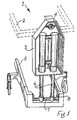
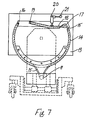
- Figs. 5 to 8 there is illustrated portion of the motor drive which comprises a combined electric motor and gear box 10 having an output pulley 11.
- the combined motor and gearbox 10 is mounted by antivibration mountings 12 on the main bed frame 3.
- An end board 13 only illustrated in some of the Figs.is mounted on the patient support platform 2 and has secured thereto an arcuate track 14.
- a drive belt 15, illustrated partly by interrupted lines is secured at one end 16 of the track 14 and is led over the output pulley 11 back onto the track 14 over a further pulley 17 into a guide 18 and is in turn secured rigidly therein.
- the guide 18 is pivotally mounted at 19 on the end board 13.
- Above the guide 14 is a camming lever 20 operable by a handle 21.
- the therapeutic bed 1 incorporates an electronic control system (not shown), of generally conventional construction, which senses and records the angular velocities of the patient support platform 2 and the pulley 11 and compares these values of angular velocity to obtain a measured velocity difference. This measured velocity difference is then compared with an acceptable pre-set velocity difference value, and if the measured velocity difference is greater than the pre-set velocity difference value a signal is sent to the motor 10 causing the motor 10 to reverse its direction of rotation and return the patient support platform 2 to the horizontal position.
- an electronic control system (not shown), of generally conventional construction, which senses and records the angular velocities of the patient support platform 2 and the pulley 11 and compares these values of angular velocity to obtain a measured velocity difference. This measured velocity difference is then compared with an acceptable pre-set velocity difference value, and if the measured velocity difference is greater than the pre-set velocity difference value a signal is sent to the motor 10 causing the motor 10 to reverse its direction of rotation and return the patient support platform 2 to the horizontal position.
- the electronic control system detects a change in the relative angular velocity of the pulley 11 and the patient support platform 2 and signals the motor 10 to stop, reverse and return the patient support platform 2 to the horizontal position, simultaneously initiating audio and visual alarm signals.
- the control unit 30 is mounted on a shaft 31 forming part of one of the pivot mountings 4 housed within a bearing 32 on the main bed frame 3. Projecting from the shaft 31 is a pin 33 engaging a slot in a disc 34 on a shaft 35 of a potentiometer 36.
- the base voltage on the potentiometer 36 it is possible to vary the angle of rotation on either side by adding or subtracting from the base voltage.
- the potentiometer 36 is connected to the controls of the gearbox motor 10 so that when the correct voltage is reached the motor is stopped and reverses in direction.
- conventional control equipment may be used to vary this base control voltage to the potentiometer not alone in absolute terms but also over time.
- Such control equipment is essentially conventional and it is not necessary to describe it.
- its use with a therapeutic bed according to the invention is particularly advantageous. Not alone is it advantageous in that by varying the arc of oscillation on either side of the vertical axis account is taken of possible injuries to a patient.
- the advantage of varying the arc of oscillation over time is that, particularly with nervous patients, it is possible to gradually increase the arc of oscillation without causing undue distress. Further, in certain cases it may be desirable to have a large arc of oscillation but due to the particular injuries or problems of the patient it may not be possible to do so. By this control method it is possible to vary the therapeutic effects of the bed. It is envisaged that a shaft position encoder could also be used.
- FIG. 11 and 12 there is illustrated portion of the patient support platform 2 on which is mounted an upstanding side member 40 for support of a patient.
- the side member 40 is mounted on a plate 41 and has a depending shaft 42.
- the shaft 42 incorporates a collar 43 (see Fig. 13) for lateral engagement within a longitudinal slot 44 in the patient support platform 2.
- Mounted on the shaft 42 is a cup-shaped housing 45 and co-operating male locking member 46 biased away from each other by spring washers 47.
- Mounted on the shaft 42 by a pin 48 is a cam 49 and handle 50. Rotation of the handle 50 in the direction of the arrow A to the position illustrated in Fig. 12 causes the cam 49 to bear against the locking member 46 and compress the spring washers 47 therebetween and the cup-shaped housing 45 thus locking the side member 40 in position.
- the advantage of such a quick release mechanism will be readily appreciated.
- FIGs. 14 and 15 there is illustrated in outline portion of an alternative construction of therapeutic bed according to the present invention indicated generally by the reference numeral 60 and parts similar to those described with reference to the previous drawings are identified by the same reference numerals and various parts of the bed are omitted.
- the patient support platform 2 is again mounted on the main bed frame 3 through the pivot mountings 4.
- the pivot mountings 4 are now mounted on a mounting block 61 which is suspended from or bearing on a cantilevered beam 62 which incorporates a load cell (not shown), the beam 62 having a free end 63 and a fixed end 64.
- the free end 63 of the beam 62 is secured to the mounting block 61 and the fixed end 64 of the beam 62 is rigidly attached to the main bed frame 3 by a bracket 65.
- the load cell feeds in conventional manner through cabling 66 a junction box 67 and in conventional manner a suitable indicator or readout.
Abstract
Description
- The present invention relates to hospital beds and more particularly to therapeutic beds.
- Therapeutic beds are used for chronic patients such as paraplegics, patients that are partially or fully paralysed, patients suffering from head injuries or other serious injuries particularly spine injuries. These therapeutic beds are used to either render a patient incapable of voluntary movement or to in some way restrict some other movements. The problem with patients who are confined is that they suffer among other things from constipation, muscular wasting, bone decalcification and bed sores.
- One of the best ways of overcoming this problem is a therapeutic hospital bed in which the patient supporting platform is mounted for controlled oscillation or controlled rotation within a bed frame relative to a bed support on which the bed frame is mounted. Generally speaking such a bed has lateral supports for a patient lying on the platform which are provided by upstanding side members detachably secured to the platform.
- DE-A-1566447 (equivalent to US 3 434 165) discloses a therapeutic bed having a patient supporting platform mounted for controlled oscillation. The patient supporting platform is oscillated with respect to a frame which is rotatably mounted on a carriage.
- It has been found that in many cases the support platform must oscillate continuously but not to the full extent of its rotating arc on either side of a vertical axis. For example, where a patient has considerable injuries to one side it may be important that the bed does not oscillate to put too much weight onto that portion of the patient. There is thus a need to provide such a bed in which the arc of oscillation can be controlled.
- A further problem arises with such beds in that because the patients are relatively immobile or almost totally immobile that the nurse or sick bay attendant has to perform every operation for the patient. In many treatments it is necessary to raise one or other end of the patient support platform or indeed, to raise the support platform horizontally.
- Further, it has been found in practice that it is essential that the drive of the bed be disconnected at certain times. Indeed, this problem has been appreciated and various methods have been proposed for solving it.
- Lastly, it has been found that the upstanding side members used to locate a patient often have to be moved and that there is need for an efficient way of disconnecting the lateral or upstanding side members.
- The present invention is directed towards overcoming these problems and to providing a more efficient construction of such a therapeutic bed.
- According to the invention there is provided a therapeutic bed of the type comprising: a patient support platform on pivot mountings in a main bed frame; a base frame; a pair of spaced-apart end uprights on the base frame and supporting the main bed frame therebetween; and a motor drive for oscillating the patient support platform relative to the main bed frame characterised in that the upstanding end uprights are individually height adjustable and at least one end upright is pivotally connected to a crankshaft which in turn is pivotally connected to the adjacent frame, the two crankshaft pivot axes being offset. The term crankshaft is used in this specification to cover a conventional crankshaft but also any linkage that allows a member to pivot about a pivot axis which pivot axis is offset from the mounting of the member relative to the pivot axis.
- The major advantage of the mounting of the uprights in this manner is that it ensures that the bed remains in a stable condition at all times. Without this mounting arrangement movement of the bed across the floor can take place when a height adjustment is made to one or both of the end uprights. This could place further unnecessary stress on the patient.
- Ideally one end upright is suspended from the base frame by the crankshaft. This is a preferable way of mounting the upright as it is closest to the ground. It could however, be easily mounted at its upper end.
- In a preferred embodiment of the invention the motor drive incorporates a drive connection, which is non-slip below a predetermined load, between it and the patient support platform and actuation means for engaging and disengaging the drive connection. The non-slip drive connection is preferably a belt. The belt drive obviates the necessity of incorporating a slip clutch to protect the motor as there is no solid linkage between the drive and the driven patient support platform and furthermore it makes it possible to engage/disengage the motor drive when the bed platform is in any position of rotation.
- In a particularly suitable embodiment of the invention the motor drive includes an electric motor, mounted on the main bed frame, driving an output pulley through a gear box and an arcuate belt engaging track on an end board connected to the patient support platform and a drive belt secured adjacent both ends of the track and engaging the output pulley intermediate its ends.
- This is a very simple drive which in the event of maintenance being required can be easily repaired and a drive belt can be replaced.
- In another embodiment of the invention there is provided a weighing means for the patient support platform. A weighing means is particularly advantageous with the present construction of therapeutic bed.
- Further, in accordance with the invention the weighing means is incorporated in the pivot mountings. This again is particularly advantageous in that by controlling and approaching as close as possible to the patient weight a more accurate measurement is achieved. This is preferable to weighing the whole bed where problems arise with what has been placed on the bed or removed from the bed since the last weighing. Further, continuous monitoring of the weight of a patient is often desirable if not essential.
- In a further embodiment of the invention there is provided a method of controlling the rotation of the patient support platform of the therapeutic bed comprising the steps of:
sensing and recording the angular velocity of the patient support platform;
sensing and recording the angular velocity of the pulley;
comparing the recorded values to obtain a measured velocity difference;
comparing this measured velocity difference with an acceptable pre-set velocity difference value causing the motor to reverse its direction of rotation if the measured velocity difference is greater than the pre-set velocity difference value and return the patient support platform to a horizontal position. - The invention will be more clearly understood from the following description of some embodiments thereof given by way of example only with reference to the accompanying drawings in which:-
- Fig. 1 is a perspective view of portion of the therapeutic bed according to the invention in the raised position,
- Fig. 2 is an end perspective view of portion of the other end of the therapeutic bed of Fig. 1,
- Fig. 3 is a side view of portion of the therapeutic bed in the raised position illustrated in Fig. 1,
- Fig. 4 is an end view of the portion of the therapeutic bed as illustrated in Fig. 1 in the lowered position,
- Fig. 5 is an end view of portion of a therapeutic bed according to the invention,
- Fig. 6 is a part sectional view in the direction of the arrows VI-VI of Fig. 5,
- Fig. 7 is a view similar to Fig. 5 showing the therapeutic bed in a slightly different position,
- Fig. 8 is a side view of another portion of the therapeutic bed,
- Fig. 9 is a side cross-sectional view of portion of the therapeutic bed,
- Fig. 10 is an enlarged sectional view of part of Fig. 9,
- Fig. 11 is a typical cross-sectional view showing an upstanding support on portion of a patient support platform for a therapeutic bed according to the invention,
- Fig. 12 is a cross-sectional view similar to Fig. 11 showing the upstanding support in the locked position,
- Fig. 13 is a detail view of portion of the upstanding support of Fig. 11,
- Fig. 14 is a side schematic view of an alternative construction of therapeutic bed according to the invention, and
- Fig. 15 is an end view of the therapeutic bed of Fig. 14.
- It must be appreciated that only portions of the therapeutic hospital bed are illustrated in the drawings. For example, the mounting of a patient support platform within a main bed frame is not fully illustrated. The main bed frame may preferably be a U-shaped bed frame but is not fully illustrated. The purpose of these drawings is to merely show the modification of similar types of therapeutic beds and therefore, for clarity many details have been deliberately omitted as they add nothing to the understanding of the invention and would merely confuse the reader.
- Referring to drawings and initially to Figs. 1 to 4 thereof there is illustrated a therapeutic hospital bed indicated generally by the
reference numeral 1 comprising apatient support platform 2 rotatably and pivotally secured within amain bed frame 3 onpivot mountings 4. Themain bed frame 3 is supported on abase frame 5 by two spaced-apart end uprights formed by a pair ofhydraulic rams 6. Each end upright is individually height adjustable and in this embodiment one of the pairs ofhydraulic rams 6 is pivotally connected to thebase frame 5 by acrankshaft 7 which in turn is pivotally connected by apivot 8 to thebase frame 5. In effect the crank shaft provides two offset pivot axes. The other pair oframs 6 is pivotally mounted on a shaft 9. Thus, when it is required to raise and lower one or both ends of thepatient support platform 2 it may be readily easily done. - For trendelenburg or reverse trendelenburg it will be seen quite clearly from Fig. 3 that any tilting of the bed in this operation does not effect the stability of the whole assembly.
- Referring to Figs. 5 to 8 there is illustrated portion of the motor drive which comprises a combined electric motor and
gear box 10 having anoutput pulley 11. The combined motor andgearbox 10 is mounted byantivibration mountings 12 on themain bed frame 3. Anend board 13 only illustrated in some of the Figs.is mounted on thepatient support platform 2 and has secured thereto anarcuate track 14. Adrive belt 15, illustrated partly by interrupted lines is secured at oneend 16 of thetrack 14 and is led over theoutput pulley 11 back onto thetrack 14 over afurther pulley 17 into aguide 18 and is in turn secured rigidly therein. Theguide 18 is pivotally mounted at 19 on theend board 13. Above theguide 14 is acamming lever 20 operable by ahandle 21. Movement of thehandle 21 from the position illustrated in Fig. 5 to the position illustrated in Fig. 7 will cause thebelt 15 to engage firmly on thepulley 11. Thus, quick engagement and disengagement of the drive may be achieved. Thebelt 15 gives a strong and positive drive that will not slip under normal operating conditions. - The
therapeutic bed 1 incorporates an electronic control system (not shown), of generally conventional construction, which senses and records the angular velocities of thepatient support platform 2 and thepulley 11 and compares these values of angular velocity to obtain a measured velocity difference. This measured velocity difference is then compared with an acceptable pre-set velocity difference value, and if the measured velocity difference is greater than the pre-set velocity difference value a signal is sent to themotor 10 causing themotor 10 to reverse its direction of rotation and return thepatient support platform 2 to the horizontal position. - Thus, in the event of an obstruction which prevents the
patient support platform 2 from rotating the electronic control system detects a change in the relative angular velocity of thepulley 11 and thepatient support platform 2 and signals themotor 10 to stop, reverse and return thepatient support platform 2 to the horizontal position, simultaneously initiating audio and visual alarm signals. - In an effort to control the rotating arc of oscillation it has been found that continuous control is most important.
- Referring therefore, to Figs. 9 and 10 there is illustrated a control unit indicated generally by the
reference numeral 30 incorporated in thepivot mountings 4. Again only portion of the control unit is illustrated for clarity. Thecontrol unit 30 is mounted on ashaft 31 forming part of one of thepivot mountings 4 housed within a bearing 32 on themain bed frame 3. Projecting from theshaft 31 is apin 33 engaging a slot in adisc 34 on ashaft 35 of apotentiometer 36. - In use, by varying the base voltage on the
potentiometer 36 it is possible to vary the angle of rotation on either side by adding or subtracting from the base voltage. Thepotentiometer 36 is connected to the controls of thegearbox motor 10 so that when the correct voltage is reached the motor is stopped and reverses in direction. It is envisaged that conventional control equipment may be used to vary this base control voltage to the potentiometer not alone in absolute terms but also over time. Such control equipment is essentially conventional and it is not necessary to describe it. However, its use with a therapeutic bed according to the invention is particularly advantageous. Not alone is it advantageous in that by varying the arc of oscillation on either side of the vertical axis account is taken of possible injuries to a patient. The advantage of varying the arc of oscillation over time is that, particularly with nervous patients, it is possible to gradually increase the arc of oscillation without causing undue distress. Further, in certain cases it may be desirable to have a large arc of oscillation but due to the particular injuries or problems of the patient it may not be possible to do so. By this control method it is possible to vary the therapeutic effects of the bed. It is envisaged that a shaft position encoder could also be used. - Referring to Figs. 11 and 12 there is illustrated portion of the
patient support platform 2 on which is mounted anupstanding side member 40 for support of a patient. Theside member 40 is mounted on aplate 41 and has a dependingshaft 42. Theshaft 42 incorporates a collar 43 (see Fig. 13) for lateral engagement within alongitudinal slot 44 in thepatient support platform 2. Mounted on theshaft 42 is a cup-shapedhousing 45 and co-operatingmale locking member 46 biased away from each other byspring washers 47. Mounted on theshaft 42 by apin 48 is acam 49 and handle 50. Rotation of thehandle 50 in the direction of the arrow A to the position illustrated in Fig. 12 causes thecam 49 to bear against the lockingmember 46 and compress thespring washers 47 therebetween and the cup-shapedhousing 45 thus locking theside member 40 in position. The advantage of such a quick release mechanism will be readily appreciated. - Referring to Figs. 14 and 15 there is illustrated in outline portion of an alternative construction of therapeutic bed according to the present invention indicated generally by the
reference numeral 60 and parts similar to those described with reference to the previous drawings are identified by the same reference numerals and various parts of the bed are omitted. In this embodiment thepatient support platform 2 is again mounted on themain bed frame 3 through thepivot mountings 4. However, thepivot mountings 4 are now mounted on a mountingblock 61 which is suspended from or bearing on a cantileveredbeam 62 which incorporates a load cell (not shown), thebeam 62 having afree end 63 and afixed end 64. Thefree end 63 of thebeam 62 is secured to the mountingblock 61 and thefixed end 64 of thebeam 62 is rigidly attached to themain bed frame 3 by abracket 65. The load cell feeds in conventional manner through cabling 66 ajunction box 67 and in conventional manner a suitable indicator or readout. - It will be appreciated that the placing of the load cell as close as possible to the
patient support platform 2 will greatly facilitate accurate weighing. Indeed, by the use of suitable controls the weight of a patient can be continuously monitored. In certain circumstances even minute variations in weight are of considerable significance.
Claims (14)
sensing and recording the angular velocity of the patient support platform (2);
sensing and recording the angular velocity of the motor (10) output pulley (11);
comparing the recorded values to obtain a measured velocity difference;
comparing this measured velocity difference with an acceptable pre-set velocity difference value, causing the motor (10) to reverse its direction of rotation if the measured velocity difference is greater than the pre-set velocity difference value and return the patient support platform (2) to a horizontal position.
Priority Applications (1)
| Application Number | Priority Date | Filing Date | Title |
|---|---|---|---|
| AT87304026T ATE68689T1 (en) | 1986-05-02 | 1987-05-05 | THERAPEUTIC BED. |
Applications Claiming Priority (2)
| Application Number | Priority Date | Filing Date | Title |
|---|---|---|---|
| IE117086A IE58731B1 (en) | 1986-05-02 | 1986-05-02 | A therapeutic bed |
| IE117086 | 1986-05-02 |
Publications (3)
| Publication Number | Publication Date |
|---|---|
| EP0248537A2 EP0248537A2 (en) | 1987-12-09 |
| EP0248537A3 EP0248537A3 (en) | 1988-08-03 |
| EP0248537B1 true EP0248537B1 (en) | 1991-10-23 |
Family
ID=11023007
Family Applications (1)
| Application Number | Title | Priority Date | Filing Date |
|---|---|---|---|
| EP87304026A Expired - Lifetime EP0248537B1 (en) | 1986-05-02 | 1987-05-05 | A therapeutic bed |
Country Status (5)
| Country | Link |
|---|---|
| US (1) | US4868937A (en) |
| EP (1) | EP0248537B1 (en) |
| AT (1) | ATE68689T1 (en) |
| DE (1) | DE3773999D1 (en) |
| IE (1) | IE58731B1 (en) |
Families Citing this family (43)
| Publication number | Priority date | Publication date | Assignee | Title |
|---|---|---|---|---|
| EP0349945A3 (en) * | 1988-07-05 | 1990-07-18 | Hermann Ruf | Bed for immobilised patients |
| US4939801A (en) * | 1988-12-22 | 1990-07-10 | Schaal Gary A | Patient transporting and turning gurney |
| WO1990014816A1 (en) * | 1989-05-30 | 1990-12-13 | Mediscus Products Limited | Therapeutic turning bed |
| US5285539A (en) * | 1992-02-22 | 1994-02-15 | Andermac, Inc. | Shower bath for a bedridden patient |
| ES2158296T3 (en) * | 1995-03-08 | 2001-09-01 | Alliance Invest Ltd | THERAPEUTIC BED. |
| US6874181B1 (en) | 1995-12-18 | 2005-04-05 | Kci Licensing, Inc. | Therapeutic bed |
| ATE235872T1 (en) * | 1995-12-18 | 2003-04-15 | Alliance Invest Ltd | THERAPEUTIC DEVICE |
| WO1999007320A2 (en) | 1997-08-08 | 1999-02-18 | Hill-Rom, Inc. | Proning bed |
| AU4836499A (en) | 1998-06-26 | 2000-01-17 | Jack J. Brooks | Proning bed |
| JP2003521964A (en) | 1999-04-21 | 2003-07-22 | ヒル−ロム サービシーズ,インコーポレイティド | Prone bed |
| EP2327385B1 (en) * | 1999-12-29 | 2016-03-16 | Hill-Rom Services, Inc. | Patient support with barrier |
| US6385801B1 (en) * | 2000-03-13 | 2002-05-14 | Kabushikikaisha Nihon M.D.M. | Rocking bed |
| AU2001245792A1 (en) * | 2000-03-17 | 2001-10-03 | Hill-Rom, Inc. | Proning bed |
| US6817363B2 (en) | 2000-07-14 | 2004-11-16 | Hill-Rom Services, Inc. | Pulmonary therapy apparatus |
| US6685605B1 (en) | 2000-10-30 | 2004-02-03 | Mark A Klossner | Exercise apparatus for the limbs and joints |
| CA2586138C (en) * | 2001-03-29 | 2010-05-04 | Kci Licensing, Inc. | Prone positioning therapeutic bed |
| US6671905B2 (en) * | 2001-03-29 | 2004-01-06 | Kci Licensing, Inc. | Prone positioning therapeutic bed |
| US20050246835A1 (en) * | 2004-05-10 | 2005-11-10 | Chin-Chuan Tu | Adjustable cribs |
| EP1604628A3 (en) * | 2004-06-11 | 2006-07-19 | Hill-Rom Services, Inc. | Hospital bed for the treatment of pulmonary diseases and nosocomial pressure ulcers |
| US20060117482A1 (en) * | 2004-12-07 | 2006-06-08 | Branson Gregory W | Touch screen control for lateral rotation of a hospital bed mattress |
| US7565708B2 (en) * | 2005-02-22 | 2009-07-28 | Jackson Roger P | Patient positioning support structure |
| US8261381B2 (en) | 2006-09-18 | 2012-09-11 | Sleep Safe Beds, Llc | Safety bed frame mounting system |
| WO2008036668A1 (en) * | 2006-09-18 | 2008-03-27 | Sleep Safe Beds, Llc. | Safety bed having elevating mattress |
| US8202226B2 (en) * | 2007-01-23 | 2012-06-19 | Kci Licensing, Inc. | Providing automated or manual guidance on dynamic patient positioning based on measured variables for ventilation control |
| US7761942B2 (en) * | 2007-10-09 | 2010-07-27 | Bedlab, Llc | Bed with adjustable patient support framework |
| US7716762B2 (en) * | 2007-10-14 | 2010-05-18 | Bedlab, Llc | Bed with sacral and trochanter pressure relieve functions |
| US7886379B2 (en) * | 2007-10-14 | 2011-02-15 | Bedlab, Llc | Support surface that modulates to cradle a patient's midsection |
| US20090094745A1 (en) * | 2007-10-14 | 2009-04-16 | Eduardo Rene Benzo | Modulating Support Surface to Aid Patient Entry and Exit |
| US7559102B1 (en) | 2008-05-14 | 2009-07-14 | Bedlab, Llc | Adjustable bed with sliding subframe for torso section |
| RU2464002C2 (en) * | 2009-06-04 | 2012-10-20 | Общество с ограниченной ответственностью "СТРОЙИНЖИНИРИНГ СМ" | Multifunctional bed |
| US8039766B2 (en) * | 2009-09-15 | 2011-10-18 | Hill-Rom Services, Inc. | Obstruction detecting force sensing system wherein the threshold force value for detecting an obstruction is set according to the configuration of the bed |
| IT1402366B1 (en) * | 2010-10-26 | 2013-09-04 | Cerioli | SENSITIVE AND STIMULATING THERAPEUTIC DEVICE |
| US9498397B2 (en) | 2012-04-16 | 2016-11-22 | Allen Medical Systems, Inc. | Dual column surgical support system |
| US9572736B2 (en) | 2014-10-28 | 2017-02-21 | Bedlab, Llc | Adjustable bed with improved shear reducing mechanism |
| US10492973B2 (en) | 2015-01-05 | 2019-12-03 | Allen Medical Systems, Inc. | Dual modality prone spine patient support apparatuses |
| US9655793B2 (en) | 2015-04-09 | 2017-05-23 | Allen Medical Systems, Inc. | Brake release mechanism for surgical table |
| US10561559B2 (en) | 2015-10-23 | 2020-02-18 | Allen Medical Systems, Inc. | Surgical patient support system and method for lateral-to-prone support of a patient during spine surgery |
| US10363189B2 (en) | 2015-10-23 | 2019-07-30 | Allen Medical Systems, Inc. | Surgical patient support for accommodating lateral-to-prone patient positioning |
| US10857054B2 (en) | 2015-11-13 | 2020-12-08 | Allen Medical Systems, Inc. | Person support apparatuses for subject repositioning |
| US11213448B2 (en) | 2017-07-31 | 2022-01-04 | Allen Medical Systems, Inc. | Rotation lockout for surgical support |
| CN109907904B (en) * | 2017-12-12 | 2020-10-23 | 山西白求恩医院(山西医学科学院) | Improved intelligent defecation nursing bed |
| US11202731B2 (en) | 2018-02-28 | 2021-12-21 | Allen Medical Systems, Inc. | Surgical patient support and methods thereof |
| US11471354B2 (en) | 2018-08-30 | 2022-10-18 | Allen Medical Systems, Inc. | Patient support with selectable pivot |
Family Cites Families (6)
| Publication number | Priority date | Publication date | Assignee | Title |
|---|---|---|---|---|
| US3267493A (en) * | 1964-07-20 | 1966-08-23 | Borg Warner | Adjustable bed |
| US3434165A (en) * | 1967-07-03 | 1969-03-25 | Vickers Ltd | Hospital bed |
| US3763507A (en) * | 1971-08-27 | 1973-10-09 | Miller Herman Inc | Pediatric bed |
| DE2445764A1 (en) * | 1974-09-25 | 1976-04-15 | Hermann Oerthel | DEVICE FOR LIFTING, REPOSITIONING AND TRANSPORTING PATIENTS |
| US4175550A (en) * | 1978-03-27 | 1979-11-27 | Leininger James R | Therapeutic bed |
| US4638516A (en) * | 1981-01-19 | 1987-01-27 | Kinetic Concepts, Inc. | Therapeutic bed support |
-
1986
- 1986-05-02 IE IE117086A patent/IE58731B1/en not_active IP Right Cessation
-
1987
- 1987-05-05 AT AT87304026T patent/ATE68689T1/en not_active IP Right Cessation
- 1987-05-05 EP EP87304026A patent/EP0248537B1/en not_active Expired - Lifetime
- 1987-05-05 DE DE8787304026T patent/DE3773999D1/en not_active Expired - Fee Related
- 1987-12-08 US US07/130,371 patent/US4868937A/en not_active Expired - Lifetime
Also Published As
| Publication number | Publication date |
|---|---|
| ATE68689T1 (en) | 1991-11-15 |
| US4868937A (en) | 1989-09-26 |
| DE3773999D1 (en) | 1991-11-28 |
| IE861170L (en) | 1987-11-02 |
| EP0248537A2 (en) | 1987-12-09 |
| EP0248537A3 (en) | 1988-08-03 |
| IE58731B1 (en) | 1993-11-03 |
Similar Documents
| Publication | Publication Date | Title |
|---|---|---|
| EP0248537B1 (en) | A therapeutic bed | |
| EP1623692B1 (en) | Equipment support rail for hospital bed | |
| US4654903A (en) | Bedsore prevention device in an invalid bed arrangement | |
| US8006332B2 (en) | Hospital bed | |
| US4372452A (en) | Transfer hoist for disabled persons | |
| US5156166A (en) | Medical patient support table | |
| US9815439B2 (en) | Patient support apparatus with lift system | |
| EP0818189B1 (en) | Device for raising or moving a person | |
| US6689075B2 (en) | Powered gait orthosis and method of utilizing same | |
| EP0858311B1 (en) | An invalid lifting device | |
| AU2001286760A1 (en) | Powered gait orthosis and method of utilizing same | |
| WO2007075701A2 (en) | Hospital bed | |
| RU2221534C1 (en) | Functional bed | |
| RU2064787C1 (en) | Functional bed | |
| JPH01151457A (en) | Treatment bed | |
| CA2259633C (en) | Improved mobile x-ray apparatus | |
| KR20220085553A (en) | Bed top of patient bed |
Legal Events
| Date | Code | Title | Description |
|---|---|---|---|
| PUAI | Public reference made under article 153(3) epc to a published international application that has entered the european phase |
Free format text: ORIGINAL CODE: 0009012 |
|
| AK | Designated contracting states |
Kind code of ref document: A2 Designated state(s): AT BE CH DE ES FR GB GR IT LI LU NL SE |
|
| PUAL | Search report despatched |
Free format text: ORIGINAL CODE: 0009013 |
|
| AK | Designated contracting states |
Kind code of ref document: A3 Designated state(s): AT BE CH DE ES FR GB GR IT LI LU NL SE |
|
| 17P | Request for examination filed |
Effective date: 19890202 |
|
| 17Q | First examination report despatched |
Effective date: 19900726 |
|
| GRAA | (expected) grant |
Free format text: ORIGINAL CODE: 0009210 |
|
| AK | Designated contracting states |
Kind code of ref document: B1 Designated state(s): AT BE CH DE ES FR GB GR IT LI LU NL SE |
|
| PG25 | Lapsed in a contracting state [announced via postgrant information from national office to epo] |
Ref country code: IT Free format text: LAPSE BECAUSE OF FAILURE TO SUBMIT A TRANSLATION OF THE DESCRIPTION OR TO PAY THE FEE WITHIN THE PRE;WARNING: LAPSES OF ITALIAN PATENTS WITH EFFECTIVE DATE BEFORE 2007 MAY HAVE OCCURRED AT ANY TIME BEFORE 2007. THE CORRECT EFFECTIVE DATE MAY BE DIFFERENT FROM THE ONE RECORDED.SCRIBED TIME-LIMIT Effective date: 19911023 Ref country code: BE Effective date: 19911023 Ref country code: AT Effective date: 19911023 Ref country code: NL Effective date: 19911023 Ref country code: SE Effective date: 19911023 Ref country code: GR Free format text: LAPSE BECAUSE OF FAILURE TO SUBMIT A TRANSLATION OF THE DESCRIPTION OR TO PAY THE FEE WITHIN THE PRESCRIBED TIME-LIMIT Effective date: 19911023 Ref country code: LI Effective date: 19911023 Ref country code: CH Effective date: 19911023 Ref country code: FR Effective date: 19911023 |
|
| REF | Corresponds to: |
Ref document number: 68689 Country of ref document: AT Date of ref document: 19911115 Kind code of ref document: T |
|
| REF | Corresponds to: |
Ref document number: 3773999 Country of ref document: DE Date of ref document: 19911128 |
|
| REG | Reference to a national code |
Ref country code: CH Ref legal event code: PL |
|
| PG25 | Lapsed in a contracting state [announced via postgrant information from national office to epo] |
Ref country code: ES Free format text: LAPSE BECAUSE OF FAILURE TO SUBMIT A TRANSLATION OF THE DESCRIPTION OR TO PAY THE FEE WITHIN THE PRESCRIBED TIME-LIMIT Effective date: 19920203 |
|
| EN | Fr: translation not filed | ||
| NLV1 | Nl: lapsed or annulled due to failure to fulfill the requirements of art. 29p and 29m of the patents act | ||
| PG25 | Lapsed in a contracting state [announced via postgrant information from national office to epo] |
Ref country code: GB Effective date: 19920505 |
|
| PG25 | Lapsed in a contracting state [announced via postgrant information from national office to epo] |
Ref country code: LU Free format text: LAPSE BECAUSE OF NON-PAYMENT OF DUE FEES Effective date: 19920531 |
|
| PLBE | No opposition filed within time limit |
Free format text: ORIGINAL CODE: 0009261 |
|
| STAA | Information on the status of an ep patent application or granted ep patent |
Free format text: STATUS: NO OPPOSITION FILED WITHIN TIME LIMIT |
|
| 26N | No opposition filed | ||
| GBPC | Gb: european patent ceased through non-payment of renewal fee |
Effective date: 19920505 |
|
| PG25 | Lapsed in a contracting state [announced via postgrant information from national office to epo] |
Ref country code: DE Effective date: 19930202 |