EP0254391A1 - Indicating device for aerosol dispensers - Google Patents
Indicating device for aerosol dispensers Download PDFInfo
- Publication number
- EP0254391A1 EP0254391A1 EP87303617A EP87303617A EP0254391A1 EP 0254391 A1 EP0254391 A1 EP 0254391A1 EP 87303617 A EP87303617 A EP 87303617A EP 87303617 A EP87303617 A EP 87303617A EP 0254391 A1 EP0254391 A1 EP 0254391A1
- Authority
- EP
- European Patent Office
- Prior art keywords
- aerosol container
- container
- outlet
- housing
- indicating
- Prior art date
- Legal status (The legal status is an assumption and is not a legal conclusion. Google has not performed a legal analysis and makes no representation as to the accuracy of the status listed.)
- Withdrawn
Links
Images


Classifications
-
- G—PHYSICS
- G06—COMPUTING; CALCULATING OR COUNTING
- G06M—COUNTING MECHANISMS; COUNTING OF OBJECTS NOT OTHERWISE PROVIDED FOR
- G06M1/00—Design features of general application
- G06M1/22—Design features of general application for visual indication of the result of count on counting mechanisms, e.g. by window with magnifying lens
-
- A—HUMAN NECESSITIES
- A61—MEDICAL OR VETERINARY SCIENCE; HYGIENE
- A61M—DEVICES FOR INTRODUCING MEDIA INTO, OR ONTO, THE BODY; DEVICES FOR TRANSDUCING BODY MEDIA OR FOR TAKING MEDIA FROM THE BODY; DEVICES FOR PRODUCING OR ENDING SLEEP OR STUPOR
- A61M15/00—Inhalators
- A61M15/0065—Inhalators with dosage or measuring devices
- A61M15/0068—Indicating or counting the number of dispensed doses or of remaining doses
- A61M15/007—Mechanical counters
- A61M15/0071—Mechanical counters having a display or indicator
- A61M15/0075—Mechanical counters having a display or indicator on a disc
-
- A—HUMAN NECESSITIES
- A61—MEDICAL OR VETERINARY SCIENCE; HYGIENE
- A61M—DEVICES FOR INTRODUCING MEDIA INTO, OR ONTO, THE BODY; DEVICES FOR TRANSDUCING BODY MEDIA OR FOR TAKING MEDIA FROM THE BODY; DEVICES FOR PRODUCING OR ENDING SLEEP OR STUPOR
- A61M15/00—Inhalators
- A61M15/009—Inhalators using medicine packages with incorporated spraying means, e.g. aerosol cans
-
- G—PHYSICS
- G06—COMPUTING; CALCULATING OR COUNTING
- G06M—COUNTING MECHANISMS; COUNTING OF OBJECTS NOT OTHERWISE PROVIDED FOR
- G06M1/00—Design features of general application
- G06M1/04—Design features of general application for driving the stage of lowest order
Definitions
- the present invention relates to a device for indicating the number of doses dispensed from an aerosol container, and, also, to aerosol devices, for example, inhalation devices by which medicaments contained in an aerosol may be administered to a patient.
- the aerosol container is placed in the tubular housing with the outlet valve member of the container communicating via a support with the outlet tube, for example, a nozzle or mouthpiece.
- the housing is then held by the patient in a more or less upright condition and the mouthpiece or nozzle of the inhalation device is placed in the mouth or nose of the patient.
- the aerosol container is pressed towards the support to dispense a dose of medicament from the container which is then inhaled by the patient.
- a disadvantage arising from use of such known devices is that the patient cannot determine the amount of medicament in the aerosol container at any given time. In an extreme case this could mean that the patient, possibly suffering from severe bronchospasm and needing a dose of medicament, will find that the aerosol container will not dispense a dose because its contents have already been exhausted.
- An object of the present invention is to provide means of overcoming this disadvantage.
- the present invention provides a device for indicating the number of doses dispensed from an aerosol container having a body and an outlet member movable relative to the body to dispense its contents in measured doses, said device comprising movement detection means responsive to relative movement between the body and the outlet member, and indicating means responsive to the movement detection means so that the indicator means is indicative of the number of movements of the body relative to the outlet member and, therefore, of the quantity of the contents of the container remaining therein or which have been discharged therefrom.
- the device of the present invention is preferably adapted for removable mounting to an aerosol container located in the housing of the medical inhalation device.
- an actuator member which comprises a ring-form member for mounting to the body of the aerosol container.
- a further member is provided which during at least a portion of the movement of the actuator member, is held stationary with respect to the outlet member. In a preferred embodiment, this further member is held stationary by abutment with a housing in which the aerosol container is received and in which the outlet member of the aerosol container is supported during relative movement of the container body.
- the device preferably comprises a ratchet wheel which is caused to rotate, by relative movement between the container body and the container housing, through a pre-determined angle.
- This wheel may itself bear markings to indicate the number of relative movements made between the aerosol container and outlet member but is preferably adapted to drive, for example, an indicator rack or toothed wheel bearing such markings, employing a suitable step-down gear ratio. This latter arrangement permits the number of doses indicated to exceed many times the number of teeth on the ratchet wheel and, hence the production of a compact device.
- an aerosol dispensing device comprising a housing in which an aerosol container can be located, an outlet leading from the housing and a support in the housing arranged to receive an outlet member of the aerosol container and having a passage through which the contents of the aerosol container may pass to the outlet, the aerosol dispensing device being provided with a dose indicating device according to the invention.
- the inhalation device shown in Figures 1 and 2 comprises a tubular housing 1 in which an aerosol container 2 can be located.
- the housing is open at one end (which will hereinafter be considered to be the top of the device for convenience of description) and is closed at the other.
- An outlet 3 leads laterally from the closed end of the housing 1.
- the outlet 3 is in the form of a mouthpiece intended for insertion into the mouth of the patient, but it may, if desired, be designed as a nozzle for insertion into the patient's nostril.
- the aerosol container 2 has an outlet valve member 4 at one end.
- This valve member can be depressed to release a measured dose from the aerosol container or, alternatively, the valve member 4 can be fixed and the main body of the container can be moved relative to the valve member to release the dose.
- the aerosol container 2 is located in the housing 1 so that one end protrudes from its open top. Spacer ribs (not shown) may be provided inside the housing to hold the external surface of the container 2 spaced from the internal surface of the housing 1.
- a support 5 is provided at the lower end of the housing 1 and has a passage 6 in which the valve member 4 of the aerosol container 2 can be located and supported.
- a second passage 7 is provided in the support 5 and is directed towards the interior of the outlet 3.
- the protruding portion of the aerosol container 2 can be depressed to move the container relative to the valve member 4 to open the valve and a dose of medicament contained in the aerosol will be discharged through the passage 7 and into the outlet 3 from which it can be inhaled by a patient.
- One dose will be released from the aerosol container each time it is fully depressed.
- FIGS 1 and 2 also show an embodiment of the dose indicating device of the present invention.
- This device A comprises an actuator member in the form of a ring-shaped cap member 8 which is removably located on the end of the protruding portion of the body of the aerosol container 2.
- the cap member 8 is retained on the body of the aerosol container 2 by means of longitudinal ribs 21 on its internal surface so that once it is on the body it cannot be removed too easily.
- the top of the cap abuts the end of the body of the container 2 and moves with the body throughout its displacement towards and away from the support 5.
- a pair of symmetrically placed spacing elements 19, of which one can be seen in Figure 1, extend from the lip of the cap member 8 into the housing 1 and slide against the internal wall of this housing so as to guide the movement of the aerosol container body therein.
- a housing 22 which defines an indicator compartment 13. This housing 22 extends from the cap member 8 along the external surface of the tubular housing 1. The length of this indicator housing 22 is such that when mounted to the tubular housing 1, it does not abut the outlet 3 as it moves downwardly with the container body.
- a driving arm 11 is slidably retained within the housing 22 and is guided for movement between two limit positions defined by stop surfaces 23a and 23b.
- the driving arm 11 supports a projection 11a which extends through and is movable within a slot 11b in the wall of the indicator housing 22 mounted adjacent the tubular housing 1. In this embodiment, projection 11a rests on the top edge 1a of the wall of the tubular housing 1.
- the driving arm 11 engages a ratchet wheel 14 which is mounted to the wall of the indicator housing 22.
- This ratchet wheel cooperates with a ratchet pawl 15.
- the ratchet wheel 14 moves downwards with the cap member 8 while the driving arm 11 remains stationary with respect to the support 5 by virtue of the abutment of projection 11a with the wall of the tubular housing 1.
- this relative linear movement between these two elements results in rotation of the ratchet wheel 14 in an anticlockwise direction (as viewed in Figure 2) through the angle subtended by a ratchet wheel tooth.
- a spur wheel 15a which is rotatable with the ratchet wheel 14, engages a toothed indicator rack 20.
- the gear ratio between the ratchet and spur wheel is such that the indicator rack moves through one "step” for a predetermined number of ratchet wheel “steps” and, hence, doses dispensed.
- the front of the housing 22 has a window (not shown) through which a portion of the indicator rack 20 is visible.
- This indicator rack carries suitable markings which are displayed through the window when the given marking registers with this window. Any suitable markings may be employed, though preferably not letters, numbers or like characters which require to be read.
- the rack can be marked with different colours of different portions so that, for example, when a red portion is displayed through the window, the patient will know that a new aerosol container must be obtained.
- the indicator rack may be marked with numbers to indicate the proportion of the contents still remaining or the number of doses dispensed from or remaining in the aerosol container.
- the markings on the indicator rack indicate that the aerosol container is empty after a predetermined number of doses, for example 200, have been dispensed, this predetermined number being less than the number of doses with which the container has been charged, say 220, so as to allow for a margin of error.
- the device illustrated in Figures 1 and 2 may be modified by replacing the indicator rack 20 by a toothed indicator wheel which is engaged by the spur wheel 15A.
- the spur wheel 15A drives this indicator wheel.
- the spur wheel 15A is replaced on the ratchet wheel 14 by a single start worm and the toothed indicator rack 20 is replaced by an indicator rack having a row of projections engageable by this single start worm.
- rotations of the ratchet wheel 14 rotates the single start worm which in turn drives the indicator rack.
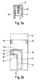
- Figure 2a shows a modification of part of what is shown in Figure 2, the resilient member 24 being replaced by a compression spring 24 ⁇ .
- Figure 2b shows a device according to the invention viewed from the opposite side to Figure 2.
- the view shows a plate 30 which forms a cover for the mechanism visible in Figure 2b.
- a slot 31 is formed in the plate 30 to define a tongue 32, having the shape of an inverted L, connected to the remainder of the cover only by a narrow bridge 33.
- An upstanding lug 34 is formed on the base of the L and a similar lug 35 is formed on the remainder of the cover on the opposite side of the slot to the lug 34.
- the material, e.g. plastics material, of which the plate is formed is sufficiently resilient that a user can urge the lugs towards one another, for example by gripping them between a thumb and finger, in which process flexing about the bridge 33 occurs.
- the axle 14a on which the wheel 14 rotates is mounted in the tongue 32, so that urging the lugs 34 and 35 together moves the wheel out of engagement with the rack 20.
- This enables the rack 20 to slide down to the end position in which it represents a value of zero doses having been dispensed. In this way the counter is reset to zero.
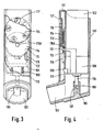
- the housing 101 is open at one end which will hereinafter be considered the top of the device for convenience of description.
- the housing 101 is closed at the other end.
- An outlet 103 leads laterally from near the closed end of the housing 101.
- the outlet 103 is in the form of a mouthpiece intended for insertion into the mouth of a patient, but it may, if desired, be designed as a nozzle for insertion into the nostril of a patient.
- the aerosol container 102 has an outlet valve member 104 at one end. This valve member can be depressed to release a dose from the aerosol container or, alternatively, the valve member 104 can be fixed and the main body of the container can be moved relatively to the valve member 104 to release a dose.
- the aerosol container 102 is located in the housing 101 so that one end protrudes from the open top of the housing as shown clearly in Figure 4. Spacer ribs, not shown, may be provided inside the housing to hold the external surface of the container spaced from the internal surface of the housing.
- a support or stem block 105 is provided at the lower end of the housing 101 and has a passage 106 in which the valve member 104 of the aerosol container 102 can be located and supported.
- a second passage 107 is provided in the support 105 and is directed towards the interior of the outlet 103.
- An actuator and container retainer member in the form of a ring 108 is guided for sliding movement in the housing 101. Locating lugs 109 protrude from the ring 108 and slide in slots 110 in the wall of the housing.
- the aerosol container 102 is fitted in the ring 108 in such a way that once it is fitted therein it cannot be removed therefrom and also so that the ring will move with the container 102 when it is depressed to open the outlet valve of the aerosol container.
- the fact that the aerosol container cannot be removed once it has been fitted prevents misuse or abuse of the product by replacement with an alternative product which may be detrimental or even dangerous to the wellbeing of a patient and contrary to medical instructions.
- a driving arm 111 extends from the ring 108 through a slot 112 in the wall of the housing 101 into an indicator compartment 113.
- the driving arm 111 engages a ratchet wheel 114 in the indicator compartment.
- the ratchet wheel co-operates with a ratchet pawl 115.
- the driving arm 111 moves downwards and forwards to the centre of the ratchet wheel 114, so engaging the next adjacent ratchet tooth.
- the driving arm 111 moves upwards causing the ratchet wheel 114 to rotate the distance of one tooth.
- Rotatable with the ratchet wheel 114 is a spur gear 115A which engages a toothed indicator wheel 116.
- the indicator wheel 116 rotates one step for each dose dispensed by depression of the body of the aerosol container 112.
- the front of the indicator housing 113 has a window 117 through which a portion of the indicator wheel 116 is indicated.
- This indicator wheel can be given suitable markings which are displayed through the window when the given markings registers with the window.
- the indicator wheel has markings "1/4", "1/2", “3/4", "F", and “E”.
- the markings "F” and “E” respectively denoting full and empty. Any suitable markings may be made on the indicator wheel.
- the wheel can be marked with different colours at different positions so that, for example, when a red portion is displayed through the window, the patient will know that a new inhalation device must be obtained.
- the indicator wheel may be marked with numbers to indicate either the number of doses dispensed from the aerosol container or the number of doses remaining to be dispensed.
- the indicator wheel is arranged to display that the aerosol container is empty after 200 doses have been dispensed, in that case the container having been charged with, say, 220 doses, to allow a margin of error.
- the invention has hereinbefore been described in relation to medical inhalation devices but it is apparent that the invention may be applied to any container having a depressable dispensing valve, to determine the quantity of product used or that which is left in the container.
Abstract
Description
- The present invention relates to a device for indicating the number of doses dispensed from an aerosol container, and, also, to aerosol devices, for example, inhalation devices by which medicaments contained in an aerosol may be administered to a patient.
- It is well known to treat patients with medicaments contained in an aerosol, for example, in bronchodilator therapy. It is also known to use for such therapy, medicaments which are contained in an aerosol and are administered to a patient by means of an inhalation device comprising a tubular housing or sleeve in which the aerosol container is located and an outlet tube leading out of the tubular housing. The aerosol containers used in such inhalation devices have an outlet valve member at one end which can be opened either by depressing the valve member while the container is held stationary or by depressing the container while the valve member is held stationary. In the use of such devices, the aerosol container is placed in the tubular housing with the outlet valve member of the container communicating via a support with the outlet tube, for example, a nozzle or mouthpiece. When used for dispensing medicaments, for example in bronchodilation therapy, the housing is then held by the patient in a more or less upright condition and the mouthpiece or nozzle of the inhalation device is placed in the mouth or nose of the patient. The aerosol container is pressed towards the support to dispense a dose of medicament from the container which is then inhaled by the patient.
- A disadvantage arising from use of such known devices is that the patient cannot determine the amount of medicament in the aerosol container at any given time. In an extreme case this could mean that the patient, possibly suffering from severe bronchospasm and needing a dose of medicament, will find that the aerosol container will not dispense a dose because its contents have already been exhausted.
- An object of the present invention is to provide means of overcoming this disadvantage.
- Accordingly, the present invention provides a device for indicating the number of doses dispensed from an aerosol container having a body and an outlet member movable relative to the body to dispense its contents in measured doses, said device comprising movement detection means responsive to relative movement between the body and the outlet member, and indicating means responsive to the movement detection means so that the indicator means is indicative of the number of movements of the body relative to the outlet member and, therefore, of the quantity of the contents of the container remaining therein or which have been discharged therefrom.
- The device of the present invention is preferably adapted for removable mounting to an aerosol container located in the housing of the medical inhalation device.
- In one preferred embodiment, an actuator member is provided which comprises a ring-form member for mounting to the body of the aerosol container. A further member is provided which during at least a portion of the movement of the actuator member, is held stationary with respect to the outlet member. In a preferred embodiment, this further member is held stationary by abutment with a housing in which the aerosol container is received and in which the outlet member of the aerosol container is supported during relative movement of the container body.
- The device preferably comprises a ratchet wheel which is caused to rotate, by relative movement between the container body and the container housing, through a pre-determined angle. This wheel may itself bear markings to indicate the number of relative movements made between the aerosol container and outlet member but is preferably adapted to drive, for example, an indicator rack or toothed wheel bearing such markings, employing a suitable step-down gear ratio. This latter arrangement permits the number of doses indicated to exceed many times the number of teeth on the ratchet wheel and, hence the production of a compact device.
- According to a further aspect of the present invention there is provided an aerosol dispensing device comprising a housing in which an aerosol container can be located, an outlet leading from the housing and a support in the housing arranged to receive an outlet member of the aerosol container and having a passage through which the contents of the aerosol container may pass to the outlet, the aerosol dispensing device being provided with a dose indicating device according to the invention.
- Embodiments of the present invention will now be described with reference to the accompanying drawings in which:
- Figure 1 is a side view, partially in section, of a first embodiment of the indicating device of the present invention mounted to a medical inhalation device;
- Figure 2 is a front view of the arrangement shown in Figure 1 in which the indicating device is shown in section;
- Figure 2a shows part of modified embodiment from one side;
- Figure 2b shows a view, from the opposite side to Figure 2 of a feature applicable both to the embodiment of Figures 1 and 2, and the modified embodiment of Figure 2a;
- Figure 3 is a front view of a further embodiment of the invention, part of a front wall of the device being broken away;
- Figure 4 is a sectional view of the device of Figure 3;
- Figures 5 and 6 are similar views illustrating one modification of the device illustrated in Figures 3 and 4; and
- Figures 7 and 8 are similar views of another modification.
- The inhalation device shown in Figures 1 and 2 comprises a
tubular housing 1 in which anaerosol container 2 can be located. The housing is open at one end (which will hereinafter be considered to be the top of the device for convenience of description) and is closed at the other. Anoutlet 3 leads laterally from the closed end of thehousing 1. In the embodiment illustrated, theoutlet 3 is in the form of a mouthpiece intended for insertion into the mouth of the patient, but it may, if desired, be designed as a nozzle for insertion into the patient's nostril. - The
aerosol container 2 has an outlet valve member 4 at one end. This valve member can be depressed to release a measured dose from the aerosol container or, alternatively, the valve member 4 can be fixed and the main body of the container can be moved relative to the valve member to release the dose. - As shown clearly in Figure 1, the
aerosol container 2 is located in thehousing 1 so that one end protrudes from its open top. Spacer ribs (not shown) may be provided inside the housing to hold the external surface of thecontainer 2 spaced from the internal surface of thehousing 1. Asupport 5 is provided at the lower end of thehousing 1 and has apassage 6 in which the valve member 4 of theaerosol container 2 can be located and supported. A second passage 7 is provided in thesupport 5 and is directed towards the interior of theoutlet 3. Thus, when the parts are in the positions shown in Figures 1 and 2, the protruding portion of theaerosol container 2 can be depressed to move the container relative to the valve member 4 to open the valve and a dose of medicament contained in the aerosol will be discharged through the passage 7 and into theoutlet 3 from which it can be inhaled by a patient. One dose will be released from the aerosol container each time it is fully depressed. - Figures 1 and 2 also show an embodiment of the dose indicating device of the present invention. This device A comprises an actuator member in the form of a ring-
shaped cap member 8 which is removably located on the end of the protruding portion of the body of theaerosol container 2. Thecap member 8 is retained on the body of theaerosol container 2 by means oflongitudinal ribs 21 on its internal surface so that once it is on the body it cannot be removed too easily. The top of the cap abuts the end of the body of thecontainer 2 and moves with the body throughout its displacement towards and away from thesupport 5. A pair of symmetrically placedspacing elements 19, of which one can be seen in Figure 1, extend from the lip of thecap member 8 into thehousing 1 and slide against the internal wall of this housing so as to guide the movement of the aerosol container body therein. - Attached to the side of the
cap member 8 and movable therewith is ahousing 22 which defines anindicator compartment 13. Thishousing 22 extends from thecap member 8 along the external surface of thetubular housing 1. The length of thisindicator housing 22 is such that when mounted to thetubular housing 1, it does not abut theoutlet 3 as it moves downwardly with the container body. - A
driving arm 11 is slidably retained within thehousing 22 and is guided for movement between two limit positions defined bystop surfaces driving arm 11 supports aprojection 11a which extends through and is movable within a slot 11b in the wall of theindicator housing 22 mounted adjacent thetubular housing 1. In this embodiment,projection 11a rests on the top edge 1a of the wall of thetubular housing 1. - The
driving arm 11 engages aratchet wheel 14 which is mounted to the wall of theindicator housing 22. This ratchet wheel cooperates with aratchet pawl 15. Whenever the body of theaerosol container 2 is depressed to open the valve member 4, theratchet wheel 14 moves downwards with thecap member 8 while thedriving arm 11 remains stationary with respect to thesupport 5 by virtue of the abutment ofprojection 11a with the wall of thetubular housing 1. In view of the engagement of thedriving arm 11 with theratchet wheel 14, this relative linear movement between these two elements results in rotation of theratchet wheel 14 in an anticlockwise direction (as viewed in Figure 2) through the angle subtended by a ratchet wheel tooth. - A
spur wheel 15a which is rotatable with theratchet wheel 14, engages atoothed indicator rack 20. The gear ratio between the ratchet and spur wheel is such that the indicator rack moves through one "step" for a predetermined number of ratchet wheel "steps" and, hence, doses dispensed. - The front of the
housing 22 has a window (not shown) through which a portion of theindicator rack 20 is visible. This indicator rack carries suitable markings which are displayed through the window when the given marking registers with this window. Any suitable markings may be employed, though preferably not letters, numbers or like characters which require to be read. For example, the rack can be marked with different colours of different portions so that, for example, when a red portion is displayed through the window, the patient will know that a new aerosol container must be obtained. In other alternatives, however, the indicator rack may be marked with numbers to indicate the proportion of the contents still remaining or the number of doses dispensed from or remaining in the aerosol container. In a convenient arrangement, the markings on the indicator rack indicate that the aerosol container is empty after a predetermined number of doses, for example 200, have been dispensed, this predetermined number being less than the number of doses with which the container has been charged, say 220, so as to allow for a margin of error. - With displacement of the
cap member 8 and housing 22 towards thesupport 5, aresilient member 24 attached to or part ofdriving arm 11, extends obliquely between thedriving arm 11 and the top wall of thehousing 22 is placed under compression and distorts. Once the pressure applied to thecap member 8 has been released, the device A returns to the position illustrated in Figures 1 and 2. The force exerted by theresilient member 24 pushes the drivingarm 11 downwards within thehousing 22 so as to engage a subsequent tooth of theratchet wheel 14. - The device illustrated in Figures 1 and 2 may be modified by replacing the
indicator rack 20 by a toothed indicator wheel which is engaged by the spur wheel 15A. Thus, on rotation of theratchet wheel 14 the spur wheel 15A drives this indicator wheel. - In a further modification of the device illusstrated in Figures 1 and 2, the spur wheel 15A is replaced on the
ratchet wheel 14 by a single start worm and thetoothed indicator rack 20 is replaced by an indicator rack having a row of projections engageable by this single start worm. Thus, in this case, rotations of theratchet wheel 14 rotates the single start worm which in turn drives the indicator rack. - Figure 2a shows a modification of part of what is shown in Figure 2, the
resilient member 24 being replaced by a compression spring 24ʹ. - Figure 2b shows a device according to the invention viewed from the opposite side to Figure 2. The view shows a
plate 30 which forms a cover for the mechanism visible in Figure 2b. Aslot 31 is formed in theplate 30 to define atongue 32, having the shape of an inverted L, connected to the remainder of the cover only by anarrow bridge 33. Anupstanding lug 34 is formed on the base of the L and asimilar lug 35 is formed on the remainder of the cover on the opposite side of the slot to thelug 34. The material, e.g. plastics material, of which the plate is formed is sufficiently resilient that a user can urge the lugs towards one another, for example by gripping them between a thumb and finger, in which process flexing about thebridge 33 occurs. Theaxle 14a on which thewheel 14 rotates is mounted in thetongue 32, so that urging thelugs rack 20. This enables therack 20 to slide down to the end position in which it represents a value of zero doses having been dispensed. In this way the counter is reset to zero. Thus, when one container has been dispensed the counter can be removed, reset to zero, and mounted on a full container, and in this way can be reused many times. Thehousing 101 is open at one end which will hereinafter be considered the top of the device for convenience of description. Thehousing 101 is closed at the other end. Anoutlet 103 leads laterally from near the closed end of thehousing 101. In the illustrated embodiment, theoutlet 103 is in the form of a mouthpiece intended for insertion into the mouth of a patient, but it may, if desired, be designed as a nozzle for insertion into the nostril of a patient. - The
aerosol container 102 has anoutlet valve member 104 at one end. This valve member can be depressed to release a dose from the aerosol container or, alternatively, thevalve member 104 can be fixed and the main body of the container can be moved relatively to thevalve member 104 to release a dose. Theaerosol container 102 is located in thehousing 101 so that one end protrudes from the open top of the housing as shown clearly in Figure 4. Spacer ribs, not shown, may be provided inside the housing to hold the external surface of the container spaced from the internal surface of the housing. A support or stemblock 105 is provided at the lower end of thehousing 101 and has apassage 106 in which thevalve member 104 of theaerosol container 102 can be located and supported. Asecond passage 107 is provided in thesupport 105 and is directed towards the interior of theoutlet 103. Thus, when the parts are in positions shown in Figures 3 and 4, the protruding portion of theaerosol container 102 can be depressed to move thecontainer 102 relatively to thevalve member 104 so that the valve will be opened and a dose of medicament contained in the aerosol will be discharged through thepassage 107 into theoutlet 103 from which it can be inhaled by the patient. One dose will be released from the aerosol container each time it is fully depressed. - An actuator and container retainer member in the form of a
ring 108 is guided for sliding movement in thehousing 101. Locating lugs 109 protrude from thering 108 and slide inslots 110 in the wall of the housing. Theaerosol container 102 is fitted in thering 108 in such a way that once it is fitted therein it cannot be removed therefrom and also so that the ring will move with thecontainer 102 when it is depressed to open the outlet valve of the aerosol container. The fact that the aerosol container cannot be removed once it has been fitted prevents misuse or abuse of the product by replacement with an alternative product which may be detrimental or even dangerous to the wellbeing of a patient and contrary to medical instructions. - A driving
arm 111 extends from thering 108 through aslot 112 in the wall of thehousing 101 into anindicator compartment 113. The drivingarm 111 engages aratchet wheel 114 in the indicator compartment. The ratchet wheel co-operates with aratchet pawl 115. When theaerosol container 102 is depressed, the drivingarm 111 moves downwards and forwards to the centre of theratchet wheel 114, so engaging the next adjacent ratchet tooth. When theaerosol container 102 is released, the drivingarm 111 moves upwards causing theratchet wheel 114 to rotate the distance of one tooth. Rotatable with theratchet wheel 114 is aspur gear 115A which engages atoothed indicator wheel 116. Thus, theindicator wheel 116 rotates one step for each dose dispensed by depression of the body of theaerosol container 112. The front of theindicator housing 113 has awindow 117 through which a portion of theindicator wheel 116 is indicated. This indicator wheel can be given suitable markings which are displayed through the window when the given markings registers with the window. Thus, in the embodiment illustrated the indicator wheel has markings "1/4", "1/2", "3/4", "F", and "E". The markings "F" and "E" respectively denoting full and empty. Any suitable markings may be made on the indicator wheel. For example, the wheel can be marked with different colours at different positions so that, for example, when a red portion is displayed through the window, the patient will know that a new inhalation device must be obtained. In other alternatives, the indicator wheel may be marked with numbers to indicate either the number of doses dispensed from the aerosol container or the number of doses remaining to be dispensed. In a convenient arrangement, the indicator wheel is arranged to display that the aerosol container is empty after 200 doses have been dispensed, in that case the container having been charged with, say, 220 doses, to allow a margin of error. - The device illustrated in Figures 5 and 6 is modified so that the
ratchet wheel 114 will drive asingle start worm 118 which in turn drives anindicator rack 119 having a row of projections engageable by the worm. The other parts of the device designated by the same references are used with reference to Figures 3 and 4. - In the modified device illustrated in Figures 7 and 8, the
ratchet wheel 114 again rotates aspur wheel 115A which engages and drives anindicator rack 120. Other parts of the device have the same reference numerals that are used in the description with reference to Figures 3 and 4. - The invention has hereinbefore been described in relation to medical inhalation devices but it is apparent that the invention may be applied to any container having a depressable dispensing valve, to determine the quantity of product used or that which is left in the container.
Claims (16)
Applications Claiming Priority (4)
| Application Number | Priority Date | Filing Date | Title |
|---|---|---|---|
| GB868610121A GB8610121D0 (en) | 1986-04-25 | 1986-04-25 | Medical aerosol devices |
| GB8610121 | 1986-04-25 | ||
| GB868619516A GB8619516D0 (en) | 1986-08-11 | 1986-08-11 | Medical inhalation device |
| GB8619516 | 1986-08-11 |
Publications (1)
| Publication Number | Publication Date |
|---|---|
| EP0254391A1 true EP0254391A1 (en) | 1988-01-27 |
Family
ID=26290673
Family Applications (1)
| Application Number | Title | Priority Date | Filing Date |
|---|---|---|---|
| EP87303617A Withdrawn EP0254391A1 (en) | 1986-04-25 | 1987-04-24 | Indicating device for aerosol dispensers |
Country Status (9)
| Country | Link |
|---|---|
| US (1) | US4817822A (en) |
| EP (1) | EP0254391A1 (en) |
| AU (1) | AU598250B2 (en) |
| CA (1) | CA1258054A (en) |
| DK (1) | DK209987A (en) |
| FI (1) | FI871799A (en) |
| GB (1) | GB2191032B (en) |
| NO (1) | NO871709L (en) |
| NZ (1) | NZ220082A (en) |
Cited By (20)
| Publication number | Priority date | Publication date | Assignee | Title |
|---|---|---|---|---|
| WO1993003785A2 (en) * | 1991-08-26 | 1993-03-04 | Minnesota Mining And Manufacturing Company | Powder dispenser |
| FR2721106A1 (en) * | 1994-06-10 | 1995-12-15 | Step | Dose counter for inhalers. |
| WO1998028033A3 (en) * | 1996-12-20 | 1998-08-13 | Norton Healthcare Ltd | Inhaler dose counter |
| WO2000009187A1 (en) | 1998-08-14 | 2000-02-24 | Rpc Wiko Gmbh & Co. Kg | Inhalator comprising a dosage counting device |
| WO2000021593A1 (en) | 1998-10-08 | 2000-04-20 | Pari GmbH Spezialisten für effektive Inhalation | Actuating device for meters and metering aerosol dispensing device with an actuating device for meters |
| EP1254678A2 (en) * | 1995-12-28 | 2002-11-06 | BOEHRINGER INGELHEIM INTERNATIONAL GmbH | Mechanical counter for a metering apparatus |
| EP1369139A1 (en) | 2002-06-03 | 2003-12-10 | 3M Innovative Properties Company | Dose indicators and dispensing canister-indicator assemblies |
| FR2842905A1 (en) * | 2002-07-29 | 2004-01-30 | Valois Sa | DOSAGE INDICATOR FOR A FLUID PRODUCT DISPENSING DEVICE |
| WO2004041334A2 (en) * | 2002-11-04 | 2004-05-21 | Bang & Olufsen Medicom A/S | Device for dispension |
| WO2004089451A1 (en) * | 2003-04-08 | 2004-10-21 | Ernst Hörlins Ingenjörsbyrå Ab | Counter for counting doses |
| WO2006027313A1 (en) * | 2004-09-04 | 2006-03-16 | Alfred Von Schuckmann | Inhaler device |
| WO2006059340A1 (en) * | 2004-12-03 | 2006-06-08 | Aparna Thirumalai Anandampilla | A resonating (alerting) metered dose inhaler |
| US7107986B2 (en) | 1997-06-10 | 2006-09-19 | Glaxo Group Limited | Dispenser with doses' counter |
| WO2006110080A1 (en) * | 2005-04-14 | 2006-10-19 | Astrazeneca Ab | Inhaler device counter |
| GB2429167A (en) * | 2005-07-27 | 2007-02-21 | Cambridge Consultants | Counting mechanism for inhaler |
| WO2007022898A2 (en) | 2005-08-24 | 2007-03-01 | Boehringer Ingelheim International Gmbh | Atomiser comprising a counter and an end of operation lock |
| GB2448112A (en) * | 2007-01-16 | 2008-10-08 | Bespak Plc | Dispensing apparatus with dose counter |
| US8082919B2 (en) | 2005-05-24 | 2011-12-27 | Shl Group Ab | Dose counter device for inhaler |
| WO2014147329A1 (en) * | 2013-03-19 | 2014-09-25 | Aptar France Sas | Fluid product dispensing device |
| US8936177B2 (en) | 2003-05-15 | 2015-01-20 | Aptar France Sas | Fluid product dispenser |
Families Citing this family (121)
| Publication number | Priority date | Publication date | Assignee | Title |
|---|---|---|---|---|
| SE448277B (en) * | 1985-04-12 | 1987-02-09 | Draco Ab | INDICATOR DEVICE WITH A DOSAGE DEVICE FOR MEDICINAL PRODUCTS |
| SE8601351D0 (en) * | 1986-03-24 | 1986-03-24 | Nilsson Sven Erik | MANAGED ADMINISTRATION OF PHYSIOLOGICALLY ACTIVE SUBJECTS |
| US5421482A (en) * | 1989-02-03 | 1995-06-06 | Senetics, Inc. | Indicator device responsive to axial force |
| US5718355A (en) * | 1989-02-03 | 1998-02-17 | Senetics, Inc. | Indicator device responsive to axial force for use with inhaler |
| SE466684B (en) * | 1989-03-07 | 1992-03-23 | Draco Ab | DEVICE INHALATOR AND PROCEDURE TO REGISTER WITH THE DEVICE INHALATOR MEDICATION |
| US5038972A (en) * | 1989-09-26 | 1991-08-13 | Technical Concepts, Inc. | Metered aerosol fragrance dispensing mechanism |
| GB8924823D0 (en) * | 1989-11-03 | 1989-12-20 | Smith Kline French Lab | Dosage inhalers |
| US5020527A (en) * | 1990-02-20 | 1991-06-04 | Texax-Glynn Corporation | Inhaler device with counter/timer means |
| DE4027669A1 (en) * | 1990-08-31 | 1992-03-05 | Pfeiffer Erich Gmbh & Co Kg | DISCHARGE DEVICE FOR MEDIA |
| GB9025654D0 (en) * | 1990-11-26 | 1991-01-09 | Riker Laboratories Inc | Device |
| AU6130694A (en) * | 1991-03-05 | 1994-08-15 | Miris Medical Corporation | An automatic aerosol medication delivery system and methods |
| US5469750A (en) * | 1991-03-05 | 1995-11-28 | Aradigm Corporation | Method and apparatus for sensing flow in two directions and automatic calibration thereof |
| AU650953B2 (en) * | 1991-03-21 | 1994-07-07 | Novartis Ag | Inhaler |
| US6119688A (en) * | 1991-08-26 | 2000-09-19 | 3M Innovative Properties Company | Powder dispenser |
| GB2262452B (en) * | 1991-12-19 | 1995-12-20 | Minnesota Mining & Mfg | Inhalation device |
| US5249718A (en) * | 1992-03-16 | 1993-10-05 | Technical Concepts | Automatic pump-type spray dispenser |
| US5397028A (en) * | 1992-04-29 | 1995-03-14 | Jesadanont; Mongkol | Automatic fluid dispenser and method |
| SE9201411D0 (en) * | 1992-05-05 | 1992-05-05 | Astra Ab | DOSAGE INHALATOR WITH INDICATING / INTERUPTING MEANS |
| US5284133A (en) * | 1992-07-23 | 1994-02-08 | Armstrong Pharmaceuticals, Inc. | Inhalation device with a dose-timer, an actuator mechanism, and patient compliance monitoring means |
| CZ287848B6 (en) * | 1992-12-18 | 2001-02-14 | Schering Corp | Inhalator of powder substances |
| BR9407608A (en) * | 1993-09-22 | 1997-01-14 | Senetics Inc | Indicating device and device for indicating aerosol drug release |
| US5505192A (en) * | 1993-11-12 | 1996-04-09 | New-Med Corporation | Dispenser monitoring system |
| US5411173A (en) * | 1993-12-17 | 1995-05-02 | Weinstein; Albert | Counter attachment for product dispensers |
| US5564414A (en) * | 1994-05-26 | 1996-10-15 | Walker; William F. | Pressurized and metered medication dose counter on removable sleeve |
| US5482030A (en) * | 1994-06-13 | 1996-01-09 | Klein; David | Aerosol and non-aerosol spray counter |
| USD361375S (en) | 1994-08-17 | 1995-08-15 | Amrep, Inc. | Aerosol dispensing cabinet |
| US5622163A (en) * | 1994-11-29 | 1997-04-22 | Iep Group, Inc. | Counter for fluid dispensers |
| US5772074A (en) * | 1995-03-31 | 1998-06-30 | Waterbury Companies, Inc. | Device and method for indicating the dispensing of a predetermined amount of a material |
| US5826571A (en) * | 1995-06-08 | 1998-10-27 | Innovative Devices, Llc | Device for use with metered dose inhalers (MDIS) |
| US6357442B1 (en) | 1995-06-08 | 2002-03-19 | Innovative Devices, Llc | Inhalation actuated device for use with metered dose inhalers (MDIS) |
| US20040237961A1 (en) * | 1995-06-08 | 2004-12-02 | Snow John Medlin | Inhalation actuated device for use with metered dose inhalers (MDIs) |
| US6672304B1 (en) | 1995-06-08 | 2004-01-06 | Innovative Devices, Llc | Inhalation actuated device for use with metered dose inhalers (MDIs) |
| US5833066A (en) * | 1996-01-02 | 1998-11-10 | Inhalermate, Llc | Carrying case for oral and nasal inhalation devices with counting mechanism |
| FR2750780B1 (en) * | 1996-07-05 | 1998-10-30 | Valois | DOSER COUNTER |
| US5785048A (en) * | 1996-08-16 | 1998-07-28 | Koerner; Steve J. | Inhaler device with means for assessing its depletion level |
| US5860387A (en) * | 1997-05-30 | 1999-01-19 | Giveen; Samuel Charles | Automatic squeeze-bottle utilization cycle counting device |
| IL122770A0 (en) | 1997-12-25 | 1998-08-16 | Gotit Ltd | Automatic spray dispenser |
| CA2315777C (en) | 1998-01-16 | 2008-12-23 | 1263152 Ontario Inc. | Indicating device for use with a dispensing device |
| US6142339A (en) | 1998-01-16 | 2000-11-07 | 1263152 Ontario Inc. | Aerosol dispensing device |
| US6358058B1 (en) | 1998-01-30 | 2002-03-19 | 1263152 Ontario Inc. | Aerosol dispensing inhaler training device |
| DE19807921A1 (en) * | 1998-02-25 | 1999-08-26 | Pfeiffer Erich Gmbh & Co Kg | Discharge control for a media donor |
| US7143764B1 (en) * | 1998-03-13 | 2006-12-05 | Astrazeneca Ab | Inhalation device |
| US6729330B2 (en) | 1998-05-05 | 2004-05-04 | Trudell Medical International | Indicating device for aerosol container |
| US6336453B1 (en) | 1999-04-30 | 2002-01-08 | Trudell Medical International | Indicating device for aerosol container |
| US6082358A (en) | 1998-05-05 | 2000-07-04 | 1263152 Ontario Inc. | Indicating device for aerosol container |
| GB2348928B (en) * | 1999-04-07 | 2001-10-31 | Bespak Plc | Improvements in or relating to dispensing apparatus |
| US6615827B2 (en) | 1999-09-08 | 2003-09-09 | Sapphire Designs, Inc. | Inhalation counter device |
| US6516799B1 (en) | 1999-09-08 | 2003-02-11 | Sapphire Design, Inc. | Inhalation counter device |
| FR2799858B1 (en) * | 1999-10-19 | 2002-01-18 | Valois Sa | DOSAGE COUNTER AND FLUID PRODUCT DISPENSER INCORPORATING SUCH A COUNTER |
| GB0004456D0 (en) * | 2000-02-26 | 2000-04-19 | Glaxo Group Ltd | Medicament dispenser |
| AU2001234005B2 (en) * | 2000-02-28 | 2006-01-19 | Pharmakodex Limited | Improvements in or relating to the delivery of oral drugs |
| GB2360218A (en) * | 2000-03-18 | 2001-09-19 | Astrazeneca Uk Ltd | Inhaler |
| GB2364649A (en) * | 2000-05-17 | 2002-02-06 | Orion Corp | Inhaler with Dose Counter |
| GB0012465D0 (en) * | 2000-05-24 | 2000-07-12 | Glaxo Group Ltd | Monitoring method |
| GB0013619D0 (en) * | 2000-06-06 | 2000-07-26 | Glaxo Group Ltd | Sample container |
| EP1301230A1 (en) * | 2000-07-15 | 2003-04-16 | Glaxo Group Limited | Medicament dispenser |
| GB2372542B (en) * | 2001-02-23 | 2003-08-20 | Bespak Plc | Dosage counting devices |
| US6745760B2 (en) | 2001-05-15 | 2004-06-08 | Trudell Medical International | Medicament applicator |
| US6651844B2 (en) | 2002-02-22 | 2003-11-25 | Schering Corporation | Spray dispenser counter |
| US7004164B2 (en) | 2002-03-21 | 2006-02-28 | Trudell Medical International | Indicating device for aerosol container |
| US6820612B2 (en) * | 2002-03-21 | 2004-11-23 | Robin Harabin | Inhaler holster |
| JP4422794B2 (en) | 2002-03-22 | 2010-02-24 | クリニカル・デザインズ・リミテッド | Administration device and manufacturing method thereof |
| US20030221687A1 (en) * | 2002-05-09 | 2003-12-04 | William Kaigler | Medication and compliance management system and method |
| ES2421402T3 (en) | 2002-06-21 | 2013-09-02 | Glaxo Group Ltd | Drive indicator for dispensing device |
| US6857427B2 (en) * | 2002-09-04 | 2005-02-22 | Ric Investments, Inc. | Interactive character for use with an aerosol medication delivery system |
| US6971381B2 (en) * | 2003-01-17 | 2005-12-06 | Stanley C. Langford | Actuation inhibitor for metered dose inhalers |
| GB0304000D0 (en) * | 2003-02-21 | 2003-03-26 | Clinical Designs Ltd | Dispenser |
| US7621273B2 (en) * | 2003-10-28 | 2009-11-24 | Trudell Medical International | Indicating device with warning dosage indicator |
| GB0327112D0 (en) * | 2003-11-21 | 2003-12-24 | Clincial Designs Ltd | Dispenser and reservoir |
| GB0328859D0 (en) | 2003-12-12 | 2004-01-14 | Clinical Designs Ltd | Dispenser and counter |
| US7100530B2 (en) | 2003-12-15 | 2006-09-05 | Trudell Medical International, Inc. | Dose indicating device |
| US7713482B2 (en) | 2003-12-18 | 2010-05-11 | The Clorox Company | Control scheme for enhanced filtered water systems |
| US7378015B2 (en) * | 2003-12-18 | 2008-05-27 | The Clorox Company | Filtered water enhancements |
| DE102004009436A1 (en) * | 2004-02-24 | 2005-10-13 | Boehringer Ingelheim International Gmbh | atomizer |
| US7670479B2 (en) * | 2004-05-24 | 2010-03-02 | PUR Water Purification, Inc. | Fluid container having an additive dispensing system |
| US20050258082A1 (en) * | 2004-05-24 | 2005-11-24 | Lund Mark T | Additive dispensing system and water filtration system |
| US8556127B2 (en) | 2004-05-24 | 2013-10-15 | Pur Water Purification Products, Inc. | Additive dispensing system for a refrigerator |
| US8893927B2 (en) | 2004-05-24 | 2014-11-25 | Pur Water Purification Products, Inc. | Cartridge for an additive dispensing system |
| SE0401773D0 (en) * | 2004-07-02 | 2004-07-02 | Astrazeneca Ab | An inhalation and a method for assessing said inhalation device |
| SE0401786D0 (en) | 2004-07-05 | 2004-07-05 | Astrazeneca Ab | Inhaler device |
| US7543582B2 (en) | 2004-09-20 | 2009-06-09 | Trudell Medical International | Dose indicating device with display elements attached to container |
| GB0425518D0 (en) | 2004-11-19 | 2004-12-22 | Clinical Designs Ltd | Substance source |
| GB0428204D0 (en) | 2004-12-23 | 2005-01-26 | Clinical Designs Ltd | Medicament container |
| JP5189369B2 (en) | 2005-01-20 | 2013-04-24 | トルーデル メディカル インターナショナル | Dispensing device |
| FR2883400B1 (en) * | 2005-03-16 | 2007-06-15 | Valois Sas | DOSAGE INDICATING DEVICE FOR DISPENSING FLUID OR PULVERULENT PRODUCTS |
| SE529956C2 (en) * | 2005-07-12 | 2008-01-15 | Medux Ab | Spraying device, method of spraying and method of manufacture of device |
| GB0518400D0 (en) * | 2005-09-09 | 2005-10-19 | Clinical Designs Ltd | Dispenser |
| GB0605150D0 (en) * | 2006-03-14 | 2006-04-26 | Glaxo Group Ltd | Counter For Use With A Medicament Dispenser |
| EP2010125B1 (en) | 2006-04-21 | 2017-01-04 | 3M Innovative Properties Company | Dose counter |
| GB0613472D0 (en) * | 2006-07-06 | 2006-08-16 | Glaxo Group Ltd | A counter and a recorder for a pill dispenser |
| US8141550B2 (en) | 2006-08-01 | 2012-03-27 | Trudell Medical International | Dispensing device |
| GB0706405D0 (en) | 2007-04-02 | 2007-05-09 | 3M Innovative Properties Co | Dose counter |
| US8656911B2 (en) | 2008-02-18 | 2014-02-25 | Glaxosmithkline Intellectual Property Development Limited | Actuation counter |
| US8082873B2 (en) | 2008-05-05 | 2011-12-27 | Trudell Medical International | Drive mechanism for an indicating device |
| US8181591B1 (en) | 2008-05-23 | 2012-05-22 | Trudell Medical International | Domed actuator for indicating device |
| US8940163B2 (en) * | 2008-07-21 | 2015-01-27 | 3M Innovative Properties Company | Apparatus for dispersing additive into a fluid stream |
| EP2626098B1 (en) | 2008-10-22 | 2020-08-19 | Trudell Medical International | Modular aerosol delivery system |
| US8381719B1 (en) | 2008-12-22 | 2013-02-26 | Trudell Medical International | Medicament delivery system with dose indicator and oversleeve actuator |
| NZ574666A (en) * | 2009-02-05 | 2009-04-30 | Nexus6 Ltd | A medicament inhaler holder that uses optical means to count and display the number of doses used |
| GB0904059D0 (en) | 2009-03-10 | 2009-04-22 | Euro Celtique Sa | Counter |
| GB0904040D0 (en) | 2009-03-10 | 2009-04-22 | Euro Celtique Sa | Counter |
| US20110031038A1 (en) * | 2009-08-07 | 2011-02-10 | Sagatulo, Inc. | Method and device for indicating doses in a drug delivery system |
| US20120080455A1 (en) * | 2010-10-01 | 2012-04-05 | Peter Jug | Hand-held food product dispenser |
| USD666493S1 (en) | 2010-11-01 | 2012-09-04 | Colgate-Palmolive Company | Cap for a container |
| USD666099S1 (en) | 2010-11-01 | 2012-08-28 | Colgate-Palmolive Company | Cap for a container |
| USD666098S1 (en) | 2010-11-01 | 2012-08-28 | Colgate-Palmolive Company | Cap for a container |
| USD666097S1 (en) | 2010-11-01 | 2012-08-28 | Colgate-Palmolive Company | Cap for a container |
| USD666492S1 (en) | 2010-11-01 | 2012-09-04 | Colgate-Palmolive Company | Cap for a container |
| USD666096S1 (en) | 2010-11-01 | 2012-08-28 | Colgate-Palmolive Company | Cap for a container |
| JP5762872B2 (en) | 2011-07-29 | 2015-08-12 | 住友化学株式会社 | Electrostatic spraying equipment |
| GB201115874D0 (en) * | 2011-09-14 | 2011-10-26 | Astrazeneca Ab | Inhaler |
| NZ595367A (en) | 2011-09-23 | 2012-02-24 | Nexus6 Ltd | A dose counting mechanism adapted to enclose a medicament delivery device |
| GB2502791B (en) | 2012-06-06 | 2014-08-20 | Consort Medical Plc | Dose indicator device |
| CA3176610A1 (en) | 2012-06-25 | 2014-01-03 | Gecko Health Innovations, Inc. | Devices, systems, and methods for adherence monitoring and patient interaction |
| US10143818B2 (en) | 2013-01-22 | 2018-12-04 | Fisher & Paykel Healthcare Limited | Dual-connector wye piece |
| US8807131B1 (en) | 2013-06-18 | 2014-08-19 | Isonea Limited | Compliance monitoring for asthma inhalers |
| WO2016059645A1 (en) * | 2014-10-14 | 2016-04-21 | Cadila Healthcare Limited | A dose counter |
| FR3028765B1 (en) * | 2014-11-21 | 2016-12-23 | Aptar France Sas | DEVICE FOR DISPENSING FLUID PRODUCT TRIGGERED BY INHALATION. |
| WO2020163473A1 (en) * | 2019-02-06 | 2020-08-13 | Lupin Inc. | Dose feedback mechanisms and assemblies for user feedback |
| US11596579B2 (en) * | 2020-09-03 | 2023-03-07 | Amir Akbar Sadigh Behzadi | Carriage with timer mechanism for holding a container |
| EP4275728A1 (en) * | 2022-05-10 | 2023-11-15 | Findair Sp. z o. o. | An actuator for an inhaler |
Citations (4)
| Publication number | Priority date | Publication date | Assignee | Title |
|---|---|---|---|---|
| GB1317315A (en) * | 1970-12-17 | 1973-05-16 | English Numbering Machines | Mechanical impulse counter |
| GB2063075A (en) * | 1979-11-07 | 1981-06-03 | Sterwin Ag | Dose indicator for inhalers |
| GB2104393A (en) * | 1981-08-13 | 1983-03-09 | Glaxo Group Ltd | Medical Inhalation Devices |
| WO1986002275A1 (en) * | 1984-10-09 | 1986-04-24 | Aktiebolaget Draco | Medical spray device |
Family Cites Families (13)
| Publication number | Priority date | Publication date | Assignee | Title |
|---|---|---|---|---|
| US1219858A (en) * | 1916-03-22 | 1917-03-20 | Herbert Harvey Patterson | Tallying device. |
| US2455962A (en) * | 1946-07-25 | 1948-12-14 | Harold R Wheeler | Recording liquid dispenser |
| US2630027A (en) * | 1948-08-07 | 1953-03-03 | Elton T Barrett | Boring and facing head |
| US3119557A (en) * | 1961-10-05 | 1964-01-28 | United States Steel Corp | Counter operator for pressurized paint can |
| DE1276294B (en) * | 1961-12-04 | 1968-08-29 | Robert J Livingston | Closure for, in particular, containers containing drugs with a counter or display device |
| US3495567A (en) * | 1968-02-20 | 1970-02-17 | Creative Packaging Inc | Pill dispenser with indicating dial |
| GB1290484A (en) * | 1968-10-02 | 1972-09-27 | ||
| US3572282A (en) * | 1969-04-04 | 1971-03-23 | Ortho Pharma Corp | Tablet dispenser with circular tablet channel |
| US3655952A (en) * | 1971-03-15 | 1972-04-11 | Portion Trol Liquor Systems In | Liquid dispenser counting mechanism |
| GB1596661A (en) * | 1977-08-16 | 1981-08-26 | Lyall R | Dispenser |
| US4350265A (en) * | 1979-10-17 | 1982-09-21 | A.G. (Patents) Limited | Liquid dispenser meter |
| GB2092991B (en) * | 1981-02-12 | 1985-01-03 | Jankel Design Robert Ltd | Box for dispensing pills at timed intervals |
| DE3302160A1 (en) * | 1983-01-22 | 1984-07-26 | Ing. Erich Pfeiffer GmbH & Co KG, 7760 Radolfzell | OPERATING DOSING DEVICE |
-
1987
- 1987-04-24 CA CA000535518A patent/CA1258054A/en not_active Expired
- 1987-04-24 AU AU71962/87A patent/AU598250B2/en not_active Expired - Fee Related
- 1987-04-24 GB GB8709743A patent/GB2191032B/en not_active Expired - Fee Related
- 1987-04-24 FI FI871799A patent/FI871799A/en not_active IP Right Cessation
- 1987-04-24 NZ NZ220082A patent/NZ220082A/en unknown
- 1987-04-24 DK DK209987A patent/DK209987A/en not_active Application Discontinuation
- 1987-04-24 US US07/042,431 patent/US4817822A/en not_active Expired - Fee Related
- 1987-04-24 EP EP87303617A patent/EP0254391A1/en not_active Withdrawn
- 1987-04-24 NO NO871709A patent/NO871709L/en unknown
Patent Citations (4)
| Publication number | Priority date | Publication date | Assignee | Title |
|---|---|---|---|---|
| GB1317315A (en) * | 1970-12-17 | 1973-05-16 | English Numbering Machines | Mechanical impulse counter |
| GB2063075A (en) * | 1979-11-07 | 1981-06-03 | Sterwin Ag | Dose indicator for inhalers |
| GB2104393A (en) * | 1981-08-13 | 1983-03-09 | Glaxo Group Ltd | Medical Inhalation Devices |
| WO1986002275A1 (en) * | 1984-10-09 | 1986-04-24 | Aktiebolaget Draco | Medical spray device |
Cited By (52)
| Publication number | Priority date | Publication date | Assignee | Title |
|---|---|---|---|---|
| EP0826386A2 (en) * | 1991-08-26 | 1998-03-04 | Minnesota Mining And Manufacturing Company | Powder dispenser |
| WO1993003785A3 (en) * | 1991-08-26 | 1993-04-29 | Minnesota Mining & Mfg | Powder dispenser |
| WO1993003785A2 (en) * | 1991-08-26 | 1993-03-04 | Minnesota Mining And Manufacturing Company | Powder dispenser |
| EP0826386A3 (en) * | 1991-08-26 | 1998-07-01 | Minnesota Mining And Manufacturing Company | Powder dispenser |
| WO1995034874A1 (en) * | 1994-06-10 | 1995-12-21 | Valois S.A. | Dose counting device for inhalators |
| US5988496A (en) * | 1994-06-10 | 1999-11-23 | Valois S.A. | Dose counter for inhalers |
| FR2721106A1 (en) * | 1994-06-10 | 1995-12-15 | Step | Dose counter for inhalers. |
| EP1254678A3 (en) * | 1995-12-28 | 2003-04-02 | BOEHRINGER INGELHEIM INTERNATIONAL GmbH | Mechanical counter for a metering apparatus |
| EP1254678A2 (en) * | 1995-12-28 | 2002-11-06 | BOEHRINGER INGELHEIM INTERNATIONAL GmbH | Mechanical counter for a metering apparatus |
| WO1998028033A3 (en) * | 1996-12-20 | 1998-08-13 | Norton Healthcare Ltd | Inhaler dose counter |
| US6446627B1 (en) | 1996-12-20 | 2002-09-10 | Norton Healthcare Limited | Inhaler dose counter |
| US7107986B2 (en) | 1997-06-10 | 2006-09-19 | Glaxo Group Limited | Dispenser with doses' counter |
| US8245704B2 (en) | 1997-06-10 | 2012-08-21 | Glaxo Group Limited | Dispenser with doses' counter |
| WO2000009187A1 (en) | 1998-08-14 | 2000-02-24 | Rpc Wiko Gmbh & Co. Kg | Inhalator comprising a dosage counting device |
| DE19846382C1 (en) * | 1998-10-08 | 2000-07-06 | Pari Gmbh | Counter and its use in inhalers, nebulizers or similar metered dose inhalers |
| US6679251B1 (en) | 1998-10-08 | 2004-01-20 | Pari Gmbh Spezialisten Fur Effektive Inhalation | Actuating device for meters and metering aerosol dispensing device with an actuating device for meters |
| US6481438B1 (en) | 1998-10-08 | 2002-11-19 | Pari Gmbh Spezialisten Fur Effetive Inhalation | Meter |
| WO2000021593A1 (en) | 1998-10-08 | 2000-04-20 | Pari GmbH Spezialisten für effektive Inhalation | Actuating device for meters and metering aerosol dispensing device with an actuating device for meters |
| EP1369139A1 (en) | 2002-06-03 | 2003-12-10 | 3M Innovative Properties Company | Dose indicators and dispensing canister-indicator assemblies |
| US7464708B2 (en) | 2002-06-03 | 2008-12-16 | 3M Innovative Properties Company | Dose indicators and dispensing canister-indicator assemblies |
| WO2004013582A1 (en) * | 2002-07-29 | 2004-02-12 | Valois Sas | Dose indicator for fluid product dispensing device |
| US7275660B2 (en) | 2002-07-29 | 2007-10-02 | Valois Sas | Dose indicator for fluid product dispensing device |
| FR2842905A1 (en) * | 2002-07-29 | 2004-01-30 | Valois Sa | DOSAGE INDICATOR FOR A FLUID PRODUCT DISPENSING DEVICE |
| US7575003B2 (en) | 2002-11-04 | 2009-08-18 | Bang & Olufsen Medicom A/S | Device for dispension |
| WO2004041334A3 (en) * | 2002-11-04 | 2004-08-19 | Bang & Olufsen Medicom As | Device for dispension |
| WO2004041334A2 (en) * | 2002-11-04 | 2004-05-21 | Bang & Olufsen Medicom A/S | Device for dispension |
| WO2004089451A1 (en) * | 2003-04-08 | 2004-10-21 | Ernst Hörlins Ingenjörsbyrå Ab | Counter for counting doses |
| US9775958B2 (en) | 2003-05-15 | 2017-10-03 | Aptar France Sas | Fluid product dispenser |
| US9370631B2 (en) | 2003-05-15 | 2016-06-21 | Aptar France Sas | Fluid product dispenser |
| US8936177B2 (en) | 2003-05-15 | 2015-01-20 | Aptar France Sas | Fluid product dispenser |
| US11013869B2 (en) | 2003-05-15 | 2021-05-25 | Aptar France Sas | Fluid product dispenser |
| WO2006027313A1 (en) * | 2004-09-04 | 2006-03-16 | Alfred Von Schuckmann | Inhaler device |
| WO2006059340A1 (en) * | 2004-12-03 | 2006-06-08 | Aparna Thirumalai Anandampilla | A resonating (alerting) metered dose inhaler |
| GB2437464A (en) * | 2004-12-03 | 2007-10-24 | Thirumalai Anandampilla Aparna | A resonating (alerting) metered dose inhaler |
| WO2006110080A1 (en) * | 2005-04-14 | 2006-10-19 | Astrazeneca Ab | Inhaler device counter |
| US7587988B2 (en) | 2005-04-14 | 2009-09-15 | Astrazeneca Ab | Inhaler device counter |
| US7819075B2 (en) | 2005-04-14 | 2010-10-26 | Astrazeneca Ab | Inhaler device counter |
| US8082919B2 (en) | 2005-05-24 | 2011-12-27 | Shl Group Ab | Dose counter device for inhaler |
| GB2429167A (en) * | 2005-07-27 | 2007-02-21 | Cambridge Consultants | Counting mechanism for inhaler |
| CN103272730B (en) * | 2005-08-24 | 2016-12-07 | 贝林格尔.英格海姆国际有限公司 | Nebulizer |
| EA012320B1 (en) * | 2005-08-24 | 2009-08-28 | Бёрингер Ингельхайм Интернациональ Гмбх | Atomiser comprising a counter and an end of operation lock |
| CN101247897B (en) * | 2005-08-24 | 2013-06-12 | 贝林格尔·英格海姆国际有限公司 | Atomiser |
| CN103272730A (en) * | 2005-08-24 | 2013-09-04 | 贝林格尔.英格海姆国际有限公司 | Atomiser |
| WO2007022898A3 (en) * | 2005-08-24 | 2007-05-31 | Boehringer Ingelheim Int | Atomiser comprising a counter and an end of operation lock |
| WO2007022898A2 (en) | 2005-08-24 | 2007-03-01 | Boehringer Ingelheim International Gmbh | Atomiser comprising a counter and an end of operation lock |
| EP2436453A1 (en) * | 2005-08-24 | 2012-04-04 | Boehringer Ingelheim International Gmbh | Atomiser comprising a counter and an end of operation lock |
| GB2448112A (en) * | 2007-01-16 | 2008-10-08 | Bespak Plc | Dispensing apparatus with dose counter |
| GB2448112B (en) * | 2007-01-16 | 2011-08-17 | Bespak Plc | Improvements in or relating to dispensing apparatus |
| WO2014147329A1 (en) * | 2013-03-19 | 2014-09-25 | Aptar France Sas | Fluid product dispensing device |
| CN105050644A (en) * | 2013-03-19 | 2015-11-11 | 阿普塔尔法国简易股份公司 | Fluid product dispensing device |
| US9555950B2 (en) | 2013-03-19 | 2017-01-31 | Aptar France Sas | Fluid product dispensing device |
| CN105050644B (en) * | 2013-03-19 | 2018-01-02 | 阿普塔尔法国简易股份公司 | Device fluid dispensing product |
Also Published As
| Publication number | Publication date |
|---|---|
| AU7196287A (en) | 1987-10-29 |
| DK209987A (en) | 1987-10-26 |
| US4817822A (en) | 1989-04-04 |
| GB2191032A (en) | 1987-12-02 |
| CA1258054A (en) | 1989-08-01 |
| FI871799A (en) | 1987-10-26 |
| AU598250B2 (en) | 1990-06-21 |
| DK209987D0 (en) | 1987-04-24 |
| NO871709D0 (en) | 1987-04-24 |
| NO871709L (en) | 1987-10-26 |
| GB8709743D0 (en) | 1987-05-28 |
| NZ220082A (en) | 1989-01-06 |
| FI871799A0 (en) | 1987-04-24 |
| GB2191032B (en) | 1990-05-16 |
Similar Documents
| Publication | Publication Date | Title |
|---|---|---|
| US4817822A (en) | Indicating device | |
| EP1362324B1 (en) | Dosage counting devices | |
| EP0559757B1 (en) | Aerosol dispenser comprising an indicator assembly | |
| JP4423457B2 (en) | Dispenser and administration device display device | |
| DK200700256U4 (en) | Inhaler counter | |
| JP4605388B2 (en) | Dosing device | |
| US7584712B2 (en) | Dose indicating device | |
| US7886934B2 (en) | Dispensing device | |
| US8082873B2 (en) | Drive mechanism for an indicating device | |
| EP2570148B1 (en) | Counter | |
| EP2099514A2 (en) | Dose counter mechanism | |
| WO2007012854A1 (en) | Canister-supported rotating ring count readout assembly for a metered dose inhaler | |
| WO2007012861A1 (en) | Canister-supported gauge-type count readout assembly for a metered dose inhaler | |
| JPS6335265A (en) | Administration amount indicator | |
| AU2015258185A1 (en) | Counter |
Legal Events
| Date | Code | Title | Description |
|---|---|---|---|
| PUAI | Public reference made under article 153(3) epc to a published international application that has entered the european phase |
Free format text: ORIGINAL CODE: 0009012 |
|
| AK | Designated contracting states |
Kind code of ref document: A1 Designated state(s): AT BE CH DE ES FR GB IT LI NL SE |
|
| 17P | Request for examination filed |
Effective date: 19880707 |
|
| 17Q | First examination report despatched |
Effective date: 19900309 |
|
| STAA | Information on the status of an ep patent application or granted ep patent |
Free format text: STATUS: THE APPLICATION HAS BEEN WITHDRAWN |
|
| 18W | Application withdrawn |
Withdrawal date: 19900623 |
|
| R18W | Application withdrawn (corrected) |
Effective date: 19900623 |
|
| RIN1 | Information on inventor provided before grant (corrected) |
Inventor name: RAND, PAUL KENNETH Inventor name: NEWELL, ROBERT EDWARD Inventor name: OSTERWELL, CAROLE ANN |