EP0254943A2 - Vehicle slip control apparatus - Google Patents
Vehicle slip control apparatus Download PDFInfo
- Publication number
- EP0254943A2 EP0254943A2 EP87110079A EP87110079A EP0254943A2 EP 0254943 A2 EP0254943 A2 EP 0254943A2 EP 87110079 A EP87110079 A EP 87110079A EP 87110079 A EP87110079 A EP 87110079A EP 0254943 A2 EP0254943 A2 EP 0254943A2
- Authority
- EP
- European Patent Office
- Prior art keywords
- slip
- driving wheel
- spinning
- control
- controlling
- Prior art date
- Legal status (The legal status is an assumption and is not a legal conclusion. Google has not performed a legal analysis and makes no representation as to the accuracy of the status listed.)
- Granted
Links
- 238000009987 spinning Methods 0.000 claims abstract description 76
- 230000001133 acceleration Effects 0.000 claims description 28
- 230000004044 response Effects 0.000 claims description 25
- 230000001965 increasing effect Effects 0.000 claims description 21
- 238000011084 recovery Methods 0.000 claims description 16
- 230000009467 reduction Effects 0.000 claims description 16
- 238000002485 combustion reaction Methods 0.000 claims description 3
- 230000003247 decreasing effect Effects 0.000 description 15
- 230000001105 regulatory effect Effects 0.000 description 11
- 238000011282 treatment Methods 0.000 description 11
- 239000000725 suspension Substances 0.000 description 9
- 238000010586 diagram Methods 0.000 description 8
- 230000005540 biological transmission Effects 0.000 description 6
- 238000012937 correction Methods 0.000 description 6
- 230000001276 controlling effect Effects 0.000 description 5
- 230000004075 alteration Effects 0.000 description 4
- 238000001514 detection method Methods 0.000 description 4
- 239000000446 fuel Substances 0.000 description 4
- 238000005070 sampling Methods 0.000 description 4
- 230000033228 biological regulation Effects 0.000 description 3
- 238000010276 construction Methods 0.000 description 3
- 238000007599 discharging Methods 0.000 description 3
- 230000000717 retained effect Effects 0.000 description 3
- 230000009471 action Effects 0.000 description 2
- 230000008901 benefit Effects 0.000 description 2
- 238000006073 displacement reaction Methods 0.000 description 2
- 238000002347 injection Methods 0.000 description 2
- 239000007924 injection Substances 0.000 description 2
- 230000002265 prevention Effects 0.000 description 2
- 230000035939 shock Effects 0.000 description 2
- 230000000694 effects Effects 0.000 description 1
- 238000002474 experimental method Methods 0.000 description 1
- 239000012530 fluid Substances 0.000 description 1
- 230000001771 impaired effect Effects 0.000 description 1
- 238000005259 measurement Methods 0.000 description 1
- 238000000034 method Methods 0.000 description 1
- 239000000203 mixture Substances 0.000 description 1
- 238000012986 modification Methods 0.000 description 1
- 230000004048 modification Effects 0.000 description 1
- 238000009877 rendering Methods 0.000 description 1
Images


Classifications
-
- B—PERFORMING OPERATIONS; TRANSPORTING
- B60—VEHICLES IN GENERAL
- B60T—VEHICLE BRAKE CONTROL SYSTEMS OR PARTS THEREOF; BRAKE CONTROL SYSTEMS OR PARTS THEREOF, IN GENERAL; ARRANGEMENT OF BRAKING ELEMENTS ON VEHICLES IN GENERAL; PORTABLE DEVICES FOR PREVENTING UNWANTED MOVEMENT OF VEHICLES; VEHICLE MODIFICATIONS TO FACILITATE COOLING OF BRAKES
- B60T8/00—Arrangements for adjusting wheel-braking force to meet varying vehicular or ground-surface conditions, e.g. limiting or varying distribution of braking force
- B60T8/17—Using electrical or electronic regulation means to control braking
- B60T8/175—Brake regulation specially adapted to prevent excessive wheel spin during vehicle acceleration, e.g. for traction control
-
- F—MECHANICAL ENGINEERING; LIGHTING; HEATING; WEAPONS; BLASTING
- F02—COMBUSTION ENGINES; HOT-GAS OR COMBUSTION-PRODUCT ENGINE PLANTS
- F02B—INTERNAL-COMBUSTION PISTON ENGINES; COMBUSTION ENGINES IN GENERAL
- F02B1/00—Engines characterised by fuel-air mixture compression
- F02B1/02—Engines characterised by fuel-air mixture compression with positive ignition
- F02B1/04—Engines characterised by fuel-air mixture compression with positive ignition with fuel-air mixture admission into cylinder
Definitions
- the present invention relates to a vehicle slip control apparatus and, more particularly, to a slip control apparatus of a vehicle designed capable of preventing the driving (driven) wheels from slipping or being spinned excessively on a road surface by controlling a torque transmitted to the driving wheels.
- Prevention of the driving wheels from an excessive slip or spinning on a road surface is extremely useful for the sake of safety as well as for an effective provision with the driving force of a vehicle.
- the prevention may be achieved by decreasing a torque to be transmitted to the driving wheels - a torque being the cause of the slip or spinning.
- Slip control systems of this type are disclosed in Japanese Patent Early Publication (Laid-Open) No. 16,948/1983 (corresponding to U. S. Patent 4.484.280) and Japanese Patent Early Publication (Laid-Open) No. 56.662/1985 (corresponding to U.S. Patent 4,583.611).
- the systems disclosed in these two prior patent applications involve, in each case, a technique using the application of a braking force by the engine to the driving wheels and a reduction in the output torque of the engine itself in order to decrease the torque to be transmitted to the driving wheels. More specifically, Japanese Patent Early Publication No.
- 16,948/1983 1 discloses a system in which the braking of the driving wheels only is carried out when a slip of the driving wheels is small, on the one hand, and the output torque of the engine is caused to be decreased, in addition to the braking of the driving wheels, when the slip of the driving wheels becomes large, on the other hand.
- Japanese Patent Early Publication No. 56,662/1985 discloses a system in which, when a slip of only one side of the left and right driving wheels is larger than that of the other side thereof, the one side thereof alone is braked and, when slips of both the left and right driving wheels are large, the both sides of the driving wheels are braked and further the output torque by the engine is caused to be reduced.
- the prior art systems as disclosed in the above patent applications are such that the braking of the driving wheels by the brake is primarily utilized and the reduction in the output torque of the engine is secondarily utilized.
- the use of the brake is advantageous in terms of a response to the slip control by the brake: however, the use of the brake is likely to cause a shock in the course of driving, leading to rendering the driving feeling poor.
- the slip control is elaborately conducted mainly using the brake, consideration should be given to the driving feeling, whereby a braking apparatus should be rendered more complex and larger than conventional ones.
- the use of the brake causes the engine to output a surplus of the torque equivalent to the braking force so that It is disadvantageous in terms of an effective use of energy leading to fuel saving.
- the present invention has the object to provide vehicle slip control apparatus capable of conducting the slip control of the driving wheels by selecting the appropriate use of the braking force applied to the driving wheels and a decreasing amount of the output torque of a power source itself, such as the engine, leading to a reduction in a frequency of the use of the brake.
- the slip control apparatus in accordance with the present invention is designed so as mainly to decrease the output torque of a power source and supplementarily to use the brake in order to reduce the slip or spinning of the driving wheels. More specifically, the slip control is carried out by reducing the output torque of a power source without braking the driving wheels, when an amount of slip or spinning of the driving wheel is small, on the one hand, and by braking the driving wheel, in addition to the use of the output torque of the power source reduced, when an amount of slip or spinning is large, on the other hand, as shown more specifically as a block diagram in FIG. 21.
- the present invention provides the slip control apparatus designed so as to prevent an amount of the slip or spinning of the driven wheel against a road surface from becoming excessively by controlling the torque transmitted to the driven wheel, which comprises output torque adjusting means for adjusting the output torque of a power source functioning a source of the output of the torque, braking force adjusting means for adjusting a braking force of the brake for a driving wheel, slip detecting means for detecting a state of a slip or spinning of the driving wheel on a road surface, and slip controlling means for carrying out the slip control by controlling said output torque adjusting means and said braking force adjusting means in response to an output from said slip detecting means, thereby reducing the output torque of said power source without using a braking force of the driving wheel when an amount of slip or spinning of the driving wheel is small, and thereby providing the driving wheel with the braking force, in addition to the reduction in the output torque of the power source, when an amount of slip or spinning of the driving wheel is large.
- the slip control apparatus with the arrangement in accordance with the present invention causes the brake to be used with low frequency and consequently avoids the excessive use of the brake, thereby leading to a reduction in the occurrence of an undesirable shock accompanied by the use of the brake and a decrease in the output of useless torques.
- the slip control is conducted by reducing the output torque of a power source as well as applying the braking force by the brake to the driving wheels, thereby lessening the large amount of the slip or spinning within short time.
- an automobile I contains a left front wheel 2 and a right front wheel 3, which function as driving (driven) wheels, and a left rear wheel 4 and a right rear wheel 5, which function as leading (undriven) wheels.
- an engine 6 as a power source, which generates torques that are transmitted to a clutch 7, a transmission 8 and a differential gear 9 and then through a left drive shaft 10 and a right drive shaft 11 to the respective left and right front wheels 2 and 3 as the driving wheels.
- the automobile 1 used is of the FF (front-engine/front-drive) type.
- the engine 6 used as the power source is shown to carry out the load control, that is, the control of the torques generated, by a throttle valve 13 mounted on an air intake passage 12. More specifically, the engine 6 is a gasoline engine of the type that the torques generated are varied with an amount of intake air.
- the control of the intake air amount may be conducted by the throttle valve 13, and the throttle valve 13 is electromagnetically opened or closed by a throttle actuator 14.
- the throttle actuator 14 may be composed of, for example, a DC motor, a stepping motor or any appropriate means that may be electromagnetically controlled by fluid pressures such as hydraulic pressures.
- the wheels 2 to 5 are provided, respectively, with a brake 21, 22, 23 and 24, each of which may be a disk brake.
- the disk brake is provided with a disk 25 rotating with the respective wheels and a caliper 26 that holds a brake pad and is provided with a wheel cylinder.
- the caliper 26 is designed so as to generate a braking force by pressing the brake pad on the disk 25 in accordance with a magnitude of the brake pressure to be supplied on the wheel cylinder.
- a master cylinder 27 functioning as a source of generating the brake pressure may be of the tandem type having two discharging openings 27a and 27b.
- a braking pipe 29, on the other. extends from the discharging opening 27b and it is branched along the line into branch pipes 29a and 29b, the branch pipe 29a being connected to the brake 21 for the left front wheel and the branch pipe 29b being connected to the brake 24 for the right rear wheel.
- the braking pipe system may be of a so-called 2-system X type.
- To the branch pipes 28a and 29a for the respective brakes 21 and 22 of the front wheels functioning as the driving wheels are connected, respectively, hydraulic pressure control valves 30 and 31 of the electromagnetic type as means for controlling a braking force.
- the brake pressures generating on the master cylinder 27 is of the type that varies with pressures generated by a brake pedal 32 applied by the force stepped by an operator D.
- each of the control valves 30 and 31 are provided with a cylinder 41 and a piston 42 inserted slidably in the cylinder 41.
- the piston 42 divides the cylinder 41 into a volume-variable chamber 43 and a control chamber 44.
- the volume-variable chamber 43 works as a passage of the brake pressure against the brakes 21 and 22 from the master cylinder 27. Accordingly, the brake pressure is caused to generate against the brakes 21 and 22 as the volume of the volume-variable chamber 43 is varied in accordance with an adjustment of a displacement position of the piston 42 and the brake pressure generated is allowed to be increased, decreased or retained.
- the piston 42 is caused to be always actuated by a return spring 45 in the direction so as to cause the volume in the volume-variable chamber 43 to be enlarged.
- the piston 42 is integrated with a check valve 46.
- an inlet to the volume-variable chamber 43 is closed, whereby the brake pressure generated by the volume-variable chamber 43 works merely on the brake 21 and 22 and do not act on the brakes 23 and 24 for the rear wheels 4 and 5 functioning as the leading wheels.
- a supply pipe 48 extending from a reservoir 47 is branched along the line into two branch pipes 48R and 48L, one branch pipe 48R being connected to the control chamber 44 of the valve 30 and the other branch pipe 48L being connected to the control chamber 44 of the valve 31.
- a pump 49 and a relief valve 50 To the branch pipes 48R and 48L are connected, respectively, supply valves SV2 and SV3 consisting each of an electromagnetically switching (open-close) valve.
- Each of the control valves 44 is additionally connected to the reservoir 47 through discharge pipes 51R and 51L, the discharge pipe 51R being connected with a discharge valve SVI consisting of an electromagnetically switching valve and the discharge pipe 51L being connected with a discharge valve SV4 consisting of an electromagnetically switching valve.
- Each of the valves SV1 to SV4, inclusive is controlled by opening or closing by way of a brake control unit U B as will be described more in detail below.
- a table below demonstrates relationships of a state of the brake pressure against the brakes 21 and 22 with operation of each of the valves SVl to SV4, inclusive.
- reference symbol U denotes generally a control unit group consisting roughly of a throttle control unit U T and a slip control unit Us as well as a brake control unit U B .
- the brake control unit U B is designed so as to control the opening or closing of each of the valves SVI to SV4. inclusive, as have been described above, on the basis of signals output from the slip control unit Us.
- the throttle control unit U T is to control the driving of the throttle actuator 14 on the basis of signals output from the slip control unit Us.
- the slip control unit U s comprises a computer of the degital type. more specifically, a microcomputer.
- the slip control unit U s is provided with signals output from each of sensors or switches 61 to 68, inclusive.
- the sensor 61 is to detect a degree of the opening of the throttle valve 13.
- the sensor 62 is to detect whether or not the clutch 7 is jointed.
- the sensor 63 is to detect the number of speeds of the transmission 8.
- the sensors 64 and 65 are, respectively, to detect the numbers of revolutions of the lefthand and righthand front wheels 2 and 3 as the driving wheels.
- the sensor 66 is to detect the number of revolutions of the rear wheel 4 as the leading wheel, that is, a vehicle speed.
- the sensor 67 is to detect an amount of operation of an accelerator 69, that is, an opening of the accelerator.
- the sensor 68 is to detect an amount of operation of a steering wheel 70, that is, a steering angle.
- Each of the sensors 64, 65 and 66 is composed using, for example, a pick-up, and each of the sensors 61, 63, 67 and 68 is composed using. for example, a potentiometer.
- the sensor 62 comprises, for example, an on/off operating switch.
- the slip control unit Us is provided basically with a CPU, a ROM, a RAM, a CLOCK and an output/input interface as well as an A/D converter or a D/A converter in accordance with input signals or output signals. This is the same when a microcomputer is employed so that detailed description thereon will be omitted herein. A description on maps, however, will be made herein by referring to those memorized in a ROM of the control unit U s .
- a slip ratio S used therefor may be defined by the following relationship (1):
- the throttle control unit U T is designed to conduct the feedback control of the throttle valve 13 (or the throttle actuator 14) so as to become a target throttle opening.
- the target throttle opening is regulated so as to be proportional by a 1-to-1 ratio to the amount of operation of the accelerator 69 by an operator D.
- FIG. 12 shows one example of the relationship of the throttle opening with the accelerator opening.
- the throttle control unit U T is also designed so as to carry out the throttle control to become a target throttle opening Tn integrated by the slip control unit Us, upon the slip control, without following the characteristic demonstrated in FIG. 12.
- the feedback control of the throttle valve 13 using the throttle control unit U T is designed in this embodiment to be carried out by way of the PI-PD control so as to compensate for a variation in response speeds of the engine 6. That is, the opening of the throttle valve 13 is regulated by way of the Pl-PD control to coincide the present slip ratio with the target slip ratio during the slip control of the driving weels. More specifically, the target throttle opening Tn during the slip control can be given by the following relationship (2) :
- the numbers of revolutions of the driving wheels are regulated by way of the feedback control so as to cause the throttle opening Tn to become a predetermined target slip ratio SET.
- the throttle opening is regulated so as for the target revolution numbers of the driven wheels, WET, to have the following relationship (3):
- FIG. 3 the PI-PD control using the throttle control unit U T as described above is indicated as a block diagram, in which reference symbol "S'" denotes an operator and suffixes "n" and "n-1" denote, respectively, values of signals at the present sampling time and at the sampling time by one previous to the present sampling time.
- the feedback control is effected using the brake control unit U B such that the spinning of the left and right driving wheels 2 and 3, respectively, is caused to become a predetermined target slip ratio S BT independently and separately from each other.
- the brake control is conducted by way of the feedback control such that the revolution number of the driving wheels WeT is determined by the following relationship (4):
- the target slip ratio S BT by the brake is determined to a degree larger than the target slip ratio SET, as will be described below.
- the slip control in this embodiment is conducted so as to lessen a frequency of the use of the brake by increasing or decreasing the engine output to become the predetermined target slip ratio SET for the throttle control or the predetermined target slip ratio WET and, further, by increasing or decreasing the torques by the brake to cause the target slip ratio SET or the target slip ratio W BT to become larger than the target brake slip ratio SET or the revolution number of the driving wheels W BT .
- the feedback control as satisfying the relationship (4) is carried out by the I-PD control that is superior in stability. More specifically, an amount of the brake operation (an amount of operation of the pistons 44 in the valves 30 and 31) Bn can be given by the following relationship (5) :
- the brake pressure When the amount of the brake operation Bn is larger than zero, that is, when it is positive, the brake pressure is increased. When the amount of the brake operation Bn is equal to or smaller than zero, that is, when it is negative, the brake pressure is decreased.
- the increase or decrease in the brake pressure is conducted by opening or closing the valves SVl to SV4, inclusive, as have been described above. Adjustment of speeds of the increase or decrease in the brake pressure is made by adjusting ratios of the opening time to the closing time (duty ratios) of the valves SVI to SV4, inclusive, by way of the duty control that is proportional to the absolute value of the brake operation amount Bn given by the relationship (5) above. Accordingly, the absolute value of the brake operation amount Bn becomes proportional to a speed of a variation in the brake pressures, and the duty ratio determining the speed of the increase or decrease in the brake pressures indicates the brake operation amount Bn.
- FIG. 4 indicates the I-PD control using the brake control unit U B , as have been described above, as a block diagram, in which reference symbol "S'" denotes an operator.
- the target slip ratio S BT by the brake, the target slip ratio SET by the engine, and the slip ratio Ss at the time of commencement of the slip control vary with a state of road surfaces, on the other hand.
- the target slip ratios S BT and SET by the engine and brake, respectively, are corrected in accordance with the slip ratio at the time of the occurrence of the maximum grip force.
- the solid line demonstrates a variation in the relationship of magnitudes of grip forces and transverse forces, represented as friction coefficients against road surfaces, during the use of spike tires with the corresponding slip ratios and the broken line demonstrates a variation in the relationship of magnitudes of grip and transverse forces, represented as friction coefficients against road surfaces, when normal tires are employed, with the corresponding slip ratios.
- FIG. 5 will be described in the course of time
- the slip ratio is so relatively large that the slip control is conducted by the decreasing generation of the torques by the engine and by the regulation by the brake.
- the throttle valve 13 is retained at a predetermined opening (open loop control).
- S 0.2 2
- o the maximum grip force of the driving wheels
- the throttle valve 13 is retained for a predetermined period of time, as have been described above, so as to cause the driving wheels to produce the maximum grip forces. This control is carried out with the attempt to prevent the acceleration G of the vehicle body from being reduced immediately after the spinning reduced, that is, to prevent the overshoot from being occurred (as shown in FIG.
- the recovery control is particularly effective to avoid the excessive reduction in the slip ratio on account of a failure of the recovery control, leading to less acceleration or to avoid the re-occurrence of the spinning to a large extent by way of the excessive recovery control because the amount of the torques is increased in accordance with the occurrence of the spinning as shown in FIG. 15. It is noted herein that, although the maximum acceleration GMA X is the one obtained at the time of the commencement of the slip control, that is, at the time t, in FIG.
- a maximum acceleration G MAX at the time when the spinning is being reduced as in this embodiment, that is, at the time t 2 in FIG. 5, is said to reflect a state of road surfaces more accurately if it is used as an amount of the torques increased by the recovery control.
- the optimum throttle opening Tvo for providing the driving wheels with torques capable of generating the maximum grip force can be theoretically given by a torque curve of the engine 6 and a transmission gear ratio.
- said T vo is determined on the basis of a map, for example, as demonstrated in FIG. 15.
- the map is prepared in accordance with experimental procedures, in which G MAX is determined to become a constant value when it is equal to or lower than 0.15 or it is equal to or higher than 0.4 with measuring errors under consideration. It is to be noted here that, since the map indicated in FIG. 15 is prepared on the basis of a particular speed mode. such as, for example, the first speed mode, a map for any other speed mode can be prepared by correcting the optimum throttle opening Tv o .
- the absorb control is conducted so as to smoothly move to the next feedback control.
- the backup control is conducted when neither the feedback control nor the recovery control can work effectively.
- the backup control to be used here is designed so as to allow a response time to become sufficiently faster than the feedback control.
- a rate of the throttle opening in the backup control is designed so as to be increased for every 14 msec of the sampling time by 0.5% of the previous throttle opening.
- a throttle opening To is determined by proportionating a throttle opening T 1 obtained by the operation of the backup control and a throttle opening T 2 obtained by the operation of the feedback control with the present slip ratio So.
- the slip control is suspended because the accelerator 69 is fully closed by the operator D. At this time, there is no risk of the re-occurrence of the spinning, even if the throttle opening of the throttle valve 13 is left in the discretion of the operator D, because the torques are caused to be decreased to a sufficient level.
- the slip control is caused to be suspended, in addition to the full closure of the accelerator 69, when the target throttle opening by the slip control becomes smaller than the throttle opening determined by FIG. 12 corresponding to the accelerator opening to be operated by the operator D.
- the slip control by the brake is suspended at the point t 3 . that is, at the point of the slip ratio being Ssc. Accordingly, the brake pressure is completely released and becomes zero after the point t 3 , as indicated in FIG. 19, so that the slip control is allowed to be conducted by the engine alone without any remaining influence from the brake.
- the brake pressure is caused to be sufficiently low in the course of transferring into the slip control by the engine alone because the target slip control S BT for the brake is set to be larger than the target slip ratio SET for the engine and the slip ratio S BC at the time of the brake release is set between the two target slip ratios, so that no spinning is likely to occur again at the time t 3 when the brake is released.
- the target slip control S BT for the brake is set to be larger than the target slip ratio SET for the engine and the slip ratio S BC at the time of the brake release is set between the two target slip ratios, so that no spinning is likely to occur again at the time t 3 when the brake is released.
- the point S BC where the braking is suspended brake pressures are caused to remain in a region represented in FIG. 19 by the oblique lines after the point ts and the braking is still working thereafter.
- FIG. 6 Main Routine
- the system is initialized, and it is discriminated in P2 whether or not a vehicle is in a stuck state or whether or not it is stuck in the mud and consequently in an unmovable state. This discrimination is made by seeing whether or not a stuck flag is set as will be described below. If NO in P2, the flow proceeds to P3 and it is then discriminated whether or not the accelerator 69 is completely closed. If NO in P3, it is then discriminated in P4 whether or not the present throttle opening is larger than the accelerator opening. If it is discriminated as NO in P4, the flow proceeds to P5 and it is then discriminated whether or not it is in the progress of the slip control. This discrimination is conducted by checking whether or not a slip control flag is set.
- FIGS 7 & 8
- the flowchart demonstrated in FIG. 7 is designed so as to interrupt into the main flowchart demonstrated in FIG. 6. for example, in every 14 msec.
- the throttle control in P23 is effected in accordance with a flowchart demonstrated in FIG. 8.
- P24 it is discriminated whether or not a flag for the slip control is set, that is, whether or not the slip control is currently under way. If YES in P24, on the one hand, the throttle valve 13 is controlled so as to select the control mode capable of reaching the predetermined target slip ratio SET for the slip control. that is, without following the peculiar character demonstrated in FIG. 12. If NO in P 24, on the other, the flow proceeds to P26 and the opening or closing of the throttle valve 13 is regulated by the operator D in his discretion, leading to the peculiar character demonstrated in FIG. 2.
- FIG. 9 (Slip Detection)
- the flowchart of FIG. 9 corresponds to P22 of FIG. 7 and is to detect whether or not the slip or spinning subject to the slip control has occurred and is to detect whether or not a vehicle is stuck.
- P3I it is discriminated whether or not the clutch 7 is completely connected. If YES in P31, it is found that the vehicle is not stuck. Then, the flow proceeds to P32 where a Stuck Flag is reset and, in P33, it is discriminated whether or not the present vehicle speed is as slow as, for example, below 6.3 km/h,
- a correction value a for the slip detection is computed in accordance with a steered angle of the steering wheel 70, as referred to in FIG. 14.
- P35 it is discriminated whether or not a slip ratio for the left front wheel 2 as the lefthand driving wheel is larger than an addition of the above correction value a to the predetermined reference value of 0.2, that is, 0.2 + ⁇ . If YES in P35. on the one hand, it is found that the left front wheel 2 is in a state of slippage so that a slip flag is set in P36. If NO in P35, the flow proceeds to P37 where a slip flag for the left front wheel 2 is reset.
- the correction value a is determined with a difference of revolutions between the inner and outer wheels at the time of the spinning, particularly a difference of revolutions between the driving wheel and the leading wheel.
- a slip ratio for the right front wheel 3 is discriminated in P38 in substantially the same manner as described above on the left front wheel 2. If YES in P38, a slip flag for the right front wheel 3 is set in P39 and, if NO in P38, a slip flag therefor is reset in P40.
- a state of slippage is determined merely by the detection of the numbers of revolutions of the driving wheels. That is, in P41, it is discriminated whether or not the number of revolutions of the left front wheel 2 is larger than that corresponding to the vehicle speed of 10 km/h. If YES in P41, a slip flag for the left front wheel 2 is set in P42 and, if NO in P41, a slip flag for the left front wheel 2 is reset.
- a slip flag for the right front wheel 3 is set or reset in P44.
- P45 and P46 in substantially the same manner as in P41 to P43.
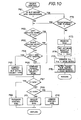
- FIG. 10 Engine Control
- FIG. 10 corresponds to P12 of FIG. 6.
- the flow proceeds to P65 and the present slip ratio is set to the driving wheel with the lower slip ratio (select-low). If NO in P64. on the other hand, the flow proceeds to P66 and the present slip ratio is set to the driving wheel with the higher slip ratio (select-high). If YES in P62 and in P63, the flow proceeds to P66 in each case.
- the select-high step in P66 is to enable the frequency of the braking to be lessened more by computing the present slip ratio in such a way that the slip or spinning of the driving wheel that is likely to slip more than the other driving wheel is controlled
- the select-low step in P65 is to enable the slip or spinning of the driving wheel likely to slip more than the other to be controlled by the brake and, at the same time, to enable the vehicle to be driven using the grip force produced by the driving wheel that is less slippery, when the vehicle is running on a road such as a split road having different friction coefficients on road surfaces with which the left and right driving wheels are in contact.
- the flow proceeds to P72 where it t is s discriminated whether or not a predetermined period of time has passed after the slip reduced, viz., whether or not a period of time for the recovery control has passed - 170 msec in this embodiment. If NO in P72, the treatments following P73 are carried out to effect the recovery control. That is, in P73, the maximum acceleration GMA X of the automobile I is measured at the point t 2 of FIG. 5 and, in P74, the optimum throttle opening Tvo capable of obtaining the maximum acceleration G MAX is set as shown in FIG. 15. Then, in P75. the optimum throttle opening Tvo obtained in P74 is corrected in accordance with the present speed mode of the transmission 8.
- the optimum throttle opening Tvo is set in P74 for a reference speed mode and then in P75, the difference of the speed mode is corrected. Thereafter. in P76, the target slip ratio SET for the slip control by the engine (throttle) and the target slip ratio S BT for the slip control by the brake are altered by estimating a road surface friction coefficient from the maximum acceleration G MAX obtained in P73. Alteration of the target slip ratios SET and S BT will be described below.
- FIG. 11 (Brake Control)
- FIG. 11 corresponds to P11 and P12 of FIG. 6.
- the flow advances to P82 and the limit value (maximum value) B L M of a response speed Bn of the brake equivalent to the duty ratio for the opening or closing control of the valves SVl to SV4 is set as a function variable in accordance with a vehicle speed - a function becoming larger as the vehicle speed gets faster.
- the limit value B LM is set in P83 to he a constant value smaller than the limit value B LM of P82.
- the treatments in P82 and P83 are arranged with the attempt unlikely to cause any vibration to occur on account of a speed of an increase or decrease in the brake pressure becoming too fast if the brake response speed Bn computed by the relationship (5) above is used as it is.
- Bn is set to the limit value B LM in P88 and then in P89, the brake pressure of the right brake 22 is increased. If NO in P87, the flow proceeds to P89 and the brake pressure thereof is increased in accordance with Bn set in P85.
- the target slip ratio SET for the engine and S BT for the brake to be altered, as demonstrated in FIG. 17, on the basis of the maximum acceleration G MAX measured in P73.
- the slip ratios SET and S BT as a rule, get larger as the maximum acceleration G MAX gets larger, and each of the limit value therefor is set.
- a slip ratio S BC is set at the point of suspension of the slip control by the brake as an intermediate value between SET and SB T .
- the intermediate value S BC is not required, as a rule, to be altered. However, for example, if the intermediate value S BC is positioned in a constant distance at a position closer to the target slip ratio SET by 20% of a deviation value of the target slip ratios SET and S BT , the intermediate value See may be altered pursuant to the alterations of the target slip ratios SET and S HT .
- the target slip ratios SET and S BT are offset as a whole in the upward or downward direction of FIG. 17. In order to make the grip force greater, they are offset in the upward direction. This can be said true as long as the slip ratio in the range of 0.2 to 0.3 or below is used because the road surface friction coefficient g is in the increasing direction up to the slip ratio being 0.2 to 0.3 as the peculiar character of spike tires, as shown in FIG. 13.
- the acceleration feeling varies with a difference between the target slip ratios SET and S BT . Acceleration is felt greater as the difference therebetween gets smaller.
- the brake control mainly works when the slip ratio of the driving wheel is larger and the engine control mainly works when the slip ratio of the driving wheel is smaller. Accordingly, if the difference between the target slip ratios SET and S BT is small, the engine control and the brake control work in a direction equally proportional to each other.
- the driving wheels arc driven in a state that the torques generated by the engine arc reduced by the brake so that the torques to be transmitted to the driving wheels are caused to be increased without a delay in a response merely by releasing the brake when the torques are required to be increased rapidly for acceleration.
- a smoothness in acceleration can be attained when the target slip ratio S BT for the brake gets large, viz., relatively large as compared to the target slip ratio SET for the engine.
- the engine control is caused to prevail over the brake control, thereby leading to the effective occurrence of a smooth variation in torques. which is the advantage of the engine control.
- a stability during the cornering can be obtained when the target slip ratio SET for the engine gets small, viz., relatively small compared to the target slip ratio S BT for the brake.
- the reduction in the target slip ratio can make the grip forces of the driving wheels smaller and, at the same time, make the transverse force as large as possible.
- the characteristic modes as represented by (1) to (4) above, may be selected automatically or manually by the operator, D (mode selection).
- the target slip ratio S BT for the brake is set larger than the target slip ratio SET for the engine so that no brake control is carried out when a degree of the slip or spinning is small, leading to a less frequency of uses of the brake, and that a barden of the brake control is lessened even when a large slip or spinning occurs.
- the intermediate point (S BC ) between the target slip ratios S BT and SET where the slip control by the brake is suspended, the brake pressure is caused to be decreased to a sufficient degree at the time of the suspension of the brake control so that a rapid variation in torques is caused unlikely to occur.
- FIG. 18 illustrates another embodiment in accordance with the present invention.
- the target slip ratio SET for the engine is set to be equal to the target slip ratio S BT for the brake
- the slip ratio S BC at the time of the suspension of the brake control is set to be larger than the target slip ratios SET and S BT .
- this embodiment can simplify the way of control, the brake pressure at the time of the suspension of the brake control may be occasionally in a very high state.
- the target slip ratio for the brake control may be set so as to be identical to the target slip ratio for the engine control, and the brake control may be designed to be conducted for a constant period of time after the commencement of the slip control, namely, after t i in FIG. 5.
- the target slip ratio for the brake control is set to be identical to the target slip ratio for the engine control and the brake control is carried out only when the slip or spinning of the driving wheels is being increased. That is, the brake control may be conducted when a variant of the revolution numbers of the driven wheels, dW D /dt, is positive or when a variant of the slip ratios, dS/dt. is positive.
- Means for adjusting the torque generated by the engine 6 may be preferably of the type regulation a factor that exert the most influence upon the engine output. That is, it is preferred that the torque output is adjusted by a so-called load control. It is preferable to adjust an amount of a mixture fuel in the otto-type engine such as,for example, a gasoline engine, and to adjust an amount of a fuel injection in a diesel engine.
- the ignition timing may be adjusted in the Otto-type engine, and the timing of the fuel injection may be adjusted in the diesel engine.
- a supercharged engine a supercharged pressure may be adjusted.
- a power source may include, in addition to an internal combustion engine, an electric motor.
- the output torque may be adjusted by the adjustment of an electric power to be supplied to the motor.
- a state of connection of the clutch 7 or a transmission gear ratio of the tranmission 8 as well as the engine may be adjusted. ln this case. a continuationaly variable transmission (CVT) is particularly preferred.
- the automobile 1 may include, in addition to the one with the front wheels 2 and 3 as the driving wheels, the ones with the rear wheels 4 and 5 as the driving wheels and with all the four wheels as the driving whee I s.
- a state of the slip or spinning of the driving wheels In order to detect a state of the slip or spinning of the driving wheels, it may be detected directly from the revolution numbers of the driving wheels as in this embodiment above and indirectly by predicting a state of the slip or spinning thereof from a state of the vehicle.
- a state of the vehicle may include, for example, an increase in the output torque of a power source or in the number of revolutions, a variation in the accelerator opening, a variation in the revolution of the driving shaft, a state of steering wheels (cornering), a state of the vehicle body lifted (acceleration), and a loadage.
- a road surface friction coefficient ⁇ upon a magnitude of atmospheric temperatures, a rainfall, a snowfall or on an iced road may be detected automatically or input manually to predict a state of the slip or spinning of the driving wheels more adequately.
- the brake to be used for the slip control may be of the electromagnetic type as well as of the hydraulic type.
- a ratio of the slip ratios, dS/dt may be used.
- As a state of the slip occurrence of the driving wheels to be used for determining an amount of the torque increased by the recovery control may be used, in addition to the maximum acceleration G MAX , for exampcl, a rotary acceleration of the driving wheels, a magnitude of the slip ratios of the driving wheels and a period of the slip continuance of the driving wheels.
- the hydraulic brake pressure regulating circuit in FIG. 2 and the sensors 64. 65 and 66 may be composed of a known ABS (anti-brake lock system).
Abstract
Description
- The present invention relates to a vehicle slip control apparatus and, more particularly, to a slip control apparatus of a vehicle designed capable of preventing the driving (driven) wheels from slipping or being spinned excessively on a road surface by controlling a torque transmitted to the driving wheels.
- Prevention of the driving wheels from an excessive slip or spinning on a road surface is extremely useful for the sake of safety as well as for an effective provision with the driving force of a vehicle. The prevention may be achieved by decreasing a torque to be transmitted to the driving wheels - a torque being the cause of the slip or spinning.
- Slip control systems of this type are disclosed in Japanese Patent Early Publication (Laid-Open) No. 16,948/1983 (corresponding to U. S. Patent 4.484.280) and Japanese Patent Early Publication (Laid-Open) No. 56.662/1985 (corresponding to U.S. Patent 4,583.611). The systems disclosed in these two prior patent applications involve, in each case, a technique using the application of a braking force by the engine to the driving wheels and a reduction in the output torque of the engine itself in order to decrease the torque to be transmitted to the driving wheels. More specifically, Japanese Patent Early Publication No. 16,948/1983 1 discloses a system in which the braking of the driving wheels only is carried out when a slip of the driving wheels is small, on the one hand, and the output torque of the engine is caused to be decreased, in addition to the braking of the driving wheels, when the slip of the driving wheels becomes large, on the other hand. Japanese Patent Early Publication No. 56,662/1985 discloses a system in which, when a slip of only one side of the left and right driving wheels is larger than that of the other side thereof, the one side thereof alone is braked and, when slips of both the left and right driving wheels are large, the both sides of the driving wheels are braked and further the output torque by the engine is caused to be reduced. The prior art systems as disclosed in the above patent applications are such that the braking of the driving wheels by the brake is primarily utilized and the reduction in the output torque of the engine is secondarily utilized.
- Since the prior art systems use mainly the brake for the slip control for the driving wheels as described immediately above, they have various disadvantages that follow.
- As the brake is continuously employed for the slip control, and is likely to be abused, it is disadvantageous in terms of durability.
- As the brake is connected to the driving wheels to an extent greater than the engine, the use of the brake is advantageous in terms of a response to the slip control by the brake: however, the use of the brake is likely to cause a shock in the course of driving, leading to rendering the driving feeling poor. When the slip control is elaborately conducted mainly using the brake, consideration should be given to the driving feeling, whereby a braking apparatus should be rendered more complex and larger than conventional ones.
- The use of the brake causes the engine to output a surplus of the torque equivalent to the braking force so that It is disadvantageous in terms of an effective use of energy leading to fuel saving.
- The present invention has the object to provide vehicle slip control apparatus capable of conducting the slip control of the driving wheels by selecting the appropriate use of the braking force applied to the driving wheels and a decreasing amount of the output torque of a power source itself, such as the engine, leading to a reduction in a frequency of the use of the brake.
- In order to achieve the above object, the slip control apparatus in accordance with the present invention is designed so as mainly to decrease the output torque of a power source and supplementarily to use the brake in order to reduce the slip or spinning of the driving wheels. More specifically, the slip control is carried out by reducing the output torque of a power source without braking the driving wheels, when an amount of slip or spinning of the driving wheel is small, on the one hand, and by braking the driving wheel, in addition to the use of the output torque of the power source reduced, when an amount of slip or spinning is large, on the other hand, as shown more specifically as a block diagram in FIG. 21.
- The present invention provides the slip control apparatus designed so as to prevent an amount of the slip or spinning of the driven wheel against a road surface from becoming excessively by controlling the torque transmitted to the driven wheel, which comprises output torque adjusting means for adjusting the output torque of a power source functioning a source of the output of the torque, braking force adjusting means for adjusting a braking force of the brake for a driving wheel, slip detecting means for detecting a state of a slip or spinning of the driving wheel on a road surface, and slip controlling means for carrying out the slip control by controlling said output torque adjusting means and said braking force adjusting means in response to an output from said slip detecting means, thereby reducing the output torque of said power source without using a braking force of the driving wheel when an amount of slip or spinning of the driving wheel is small, and thereby providing the driving wheel with the braking force, in addition to the reduction in the output torque of the power source, when an amount of slip or spinning of the driving wheel is large.
- The slip control apparatus with the arrangement in accordance with the present invention causes the brake to be used with low frequency and consequently avoids the excessive use of the brake, thereby leading to a reduction in the occurrence of an undesirable shock accompanied by the use of the brake and a decrease in the output of useless torques.
- When an amount of the slip or spinning is large, of course, the slip control is conducted by reducing the output torque of a power source as well as applying the braking force by the brake to the driving wheels, thereby lessening the large amount of the slip or spinning within short time.
- Other objects and advantages of the present invention will become apparent from the course of the following description by way of embodiments.
-
- FIG. I is an overall schematic diagram illustrating an embodiment according to the present invention.
- FIG. 2 is a diagram illustrating a hydraulic brake control circuit.
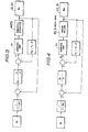
- FIG. 3 is a block diagram illustrating a feedback control of a throttle valve.
- FIG. 4 is a block diagram illustrating a feedback control of a brake.
- FIG. 5 is a diagramatical graph illustrating a control example in accordance with the present invention.
- FIGS. 6 to 11 are each a flowchart illustrating a control example in accordance with the present invention.
- FIG. 12 is a graph illustrating the character of the throttle opening with respect to the accelerator opening when no slip control is conducted.
- FIG. 13 is a graph showing the relationship of the grip force of the driving wheel with the transverse force thereof and the relationship of slip ratios with road surface friction coefficients.
- FIG. 14 is a graph showing correction values for correcting slip ratios at the commencement of the slip control in accordance with angles of the steering handle.
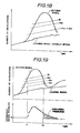
- FIG. 15 is a graph showing the optimum throttle opening corresponding to the maximum acceleration during the recovery control.
- FIG. 16 is a graph showing the relationship of slip ratios for the absorb control with the throttle opening.
- FIG. 17 is a table illustrating an example of a map for determining a target slip ratio.
- FIG. 18 is a graph illustrating another embodiment of the control according to the present invention, corresponding to FIG. 5.
- FIG. 19 is a graph illustrating a state of hydraulic brake pressures before or after the suspension of the slip control by the brake.
- FIG. 20 is a graph illustrating the recovery control.
- FIG. 21 is a schematic diagram showing the overall construction of the present invention.
- In FIG. I, an automobile I contains a
left front wheel 2 and a right front wheel 3, which function as driving (driven) wheels, and a left rear wheel 4 and a rightrear wheel 5, which function as leading (undriven) wheels. In the front of the automobile I is mounted anengine 6 as a power source, which generates torques that are transmitted to aclutch 7, atransmission 8 and a differential gear 9 and then through aleft drive shaft 10 and a right drive shaft 11 to the respective left and rightfront wheels 2 and 3 as the driving wheels. In this embodiment, theautomobile 1 used is of the FF (front-engine/front-drive) type. - In this embodiment, the
engine 6 used as the power source is shown to carry out the load control, that is, the control of the torques generated, by athrottle valve 13 mounted on anair intake passage 12. More specifically, theengine 6 is a gasoline engine of the type that the torques generated are varied with an amount of intake air. The control of the intake air amount may be conducted by thethrottle valve 13, and thethrottle valve 13 is electromagnetically opened or closed by athrottle actuator 14. Thethrottle actuator 14 may be composed of, for example, a DC motor, a stepping motor or any appropriate means that may be electromagnetically controlled by fluid pressures such as hydraulic pressures. - The
wheels 2 to 5 are provided, respectively, with abrake disk 25 rotating with the respective wheels and acaliper 26 that holds a brake pad and is provided with a wheel cylinder. Thecaliper 26 is designed so as to generate a braking force by pressing the brake pad on thedisk 25 in accordance with a magnitude of the brake pressure to be supplied on the wheel cylinder. - A
master cylinder 27 functioning as a source of generating the brake pressure may be of the tandem type having twodischarging openings braking pipe 28, on the one hand, extends from the discharging opening 27a and it is branched along the line intobranch pipes branch pipe 28a being connected to thebrake 22, more specifically, to the wheel cylinder thereof, for the right front wheel and thebranch pipe 28b being connected to thebrake 23 for the left rear wheel. Abraking pipe 29, on the other. extends from the discharging opening 27b and it is branched along the line intobranch pipes branch pipe 29a being connected to thebrake 21 for the left front wheel and thebranch pipe 29b being connected to thebrake 24 for the right rear wheel. As described hereinabove, the braking pipe system may be of a so-called 2-system X type. To thebranch pipes respective brakes pressure control valves master cylinder 27 is of the type that varies with pressures generated by a brake pedal 32 applied by the force stepped by an operator D. - As shown specifically in FIG. 2, each of the
control valves piston 42 inserted slidably in the cylinder 41. Thepiston 42 divides the cylinder 41 into a volume-variable chamber 43 and acontrol chamber 44. The volume-variable chamber 43 works as a passage of the brake pressure against thebrakes master cylinder 27. Accordingly, the brake pressure is caused to generate against thebrakes variable chamber 43 is varied in accordance with an adjustment of a displacement position of thepiston 42 and the brake pressure generated is allowed to be increased, decreased or retained. - The
piston 42 is caused to be always actuated by areturn spring 45 in the direction so as to cause the volume in the volume-variable chamber 43 to be enlarged. Thepiston 42 is integrated with acheck valve 46. When thepiston 42 is caused to displace in the direction causing the volume in the volume-variable chamber 43 to be decreased, an inlet to the volume-variable chamber 43 is closed, whereby the brake pressure generated by the volume-variable chamber 43 works merely on thebrake brakes rear wheels 4 and 5 functioning as the leading wheels. - The adjustment of the displacement position of the
piston 42 is carried out by adjusting the regulation of the hydraulic pressure against thecontrol chamber 44. More specifically, asupply pipe 48 extending from areservoir 47 is branched along the line into twobranch pipes branch pipe 48R being connected to thecontrol chamber 44 of thevalve 30 and theother branch pipe 48L being connected to thecontrol chamber 44 of thevalve 31. To thesupply pipe 48 are connected apump 49 and arelief valve 50. To thebranch pipes control valves 44 is additionally connected to thereservoir 47 through discharge pipes 51R and 51L, the discharge pipe 51R being connected with a discharge valve SVI consisting of an electromagnetically switching valve and the discharge pipe 51L being connected with a discharge valve SV4 consisting of an electromagnetically switching valve. - When the braking is effected using each of the hydraulic
pressure regulating valves check valve 46. When the brake pressure to be generated by the hydraulicpressure regulating valve pressure regulating valve master cylinder 27 is caused to communicate with thebrake - Each of the valves SV1 to SV4, inclusive, is controlled by opening or closing by way of a brake control unit UB as will be described more in detail below. A table below demonstrates relationships of a state of the brake pressure against the
brakes 
- Referring to FIG. 1, reference symbol U denotes generally a control unit group consisting roughly of a throttle control unit UT and a slip control unit Us as well as a brake control unit UB. The brake control unit UB is designed so as to control the opening or closing of each of the valves SVI to SV4. inclusive, as have been described above, on the basis of signals output from the slip control unit Us. The throttle control unit UT is to control the driving of the
throttle actuator 14 on the basis of signals output from the slip control unit Us. - The slip control unit Us comprises a computer of the degital type. more specifically, a microcomputer. The slip control unit Us is provided with signals output from each of sensors or switches 61 to 68, inclusive. The
sensor 61 is to detect a degree of the opening of thethrottle valve 13. Thesensor 62 is to detect whether or not the clutch 7 is jointed. Thesensor 63 is to detect the number of speeds of thetransmission 8. Thesensors front wheels 2 and 3 as the driving wheels. Thesensor 66 is to detect the number of revolutions of the rear wheel 4 as the leading wheel, that is, a vehicle speed. Thesensor 67 is to detect an amount of operation of anaccelerator 69, that is, an opening of the accelerator. Thesensor 68 is to detect an amount of operation of asteering wheel 70, that is, a steering angle. Each of thesensors sensors sensor 62 comprises, for example, an on/off operating switch. - The slip control unit Us is provided basically with a CPU, a ROM, a RAM, a CLOCK and an output/input interface as well as an A/D converter or a D/A converter in accordance with input signals or output signals. This is the same when a microcomputer is employed so that detailed description thereon will be omitted herein. A description on maps, however, will be made herein by referring to those memorized in a ROM of the control unit Us.
- The following is a description on the control manner of the control unit group U. A slip ratio S used therefor may be defined by the following relationship (1):

- where WD is the number of revolutions of the driving wheels (2 and 3) and
- WL is the number of revolutions of the leading wheel (4), that is, the vehicle speed.
- The throttle control unit UT is designed to conduct the feedback control of the throttle valve 13 (or the throttle actuator 14) so as to become a target throttle opening. When no slip control is conducted during the throttle control, the target throttle opening is regulated so as to be proportional by a 1-to-1 ratio to the amount of operation of the
accelerator 69 by an operator D. FIG. 12 shows one example of the relationship of the throttle opening with the accelerator opening. The throttle control unit UT is also designed so as to carry out the throttle control to become a target throttle opening Tn integrated by the slip control unit Us, upon the slip control, without following the characteristic demonstrated in FIG. 12. - The feedback control of the
throttle valve 13 using the throttle control unit UT is designed in this embodiment to be carried out by way of the PI-PD control so as to compensate for a variation in response speeds of theengine 6. That is, the opening of thethrottle valve 13 is regulated by way of the Pl-PD control to coincide the present slip ratio with the target slip ratio during the slip control of the driving weels. More specifically, the target throttle opening Tn during the slip control can be given by the following relationship (2) :
- where WL is the number of revolutions of the leading wheel (4) ;
- WD is the number of revolutions of the driving wheels (2 and 3) ;
- Kp is a proportional coefficient;
- Kl is an integral coefficient;
- Fp is a proportional coefficient:
- Fo is a differential coefficient; and
- SET is a target slip ratio for the throttle control.
- As given by the above relationship (2), the numbers of revolutions of the driving wheels are regulated by way of the feedback control so as to cause the throttle opening Tn to become a predetermined target slip ratio SET. In other words, as is apparent from the above relationship (1), the throttle opening is regulated so as for the target revolution numbers of the driven wheels, WET, to have the following relationship (3):

- In FIG. 3, the PI-PD control using the throttle control unit UT as described above is indicated as a block diagram, in which reference symbol "S'" denotes an operator and suffixes "n" and "n-1" denote, respectively, values of signals at the present sampling time and at the sampling time by one previous to the present sampling time.
- At the time of the slip control, the feedback control is effected using the brake control unit UB such that the spinning of the left and
right driving wheels 2 and 3, respectively, is caused to become a predetermined target slip ratio SBT independently and separately from each other. In other words, the brake control is conducted by way of the feedback control such that the revolution number of the driving wheels WeT is determined by the following relationship (4):
- In this embodiment, the target slip ratio SBT by the brake is determined to a degree larger than the target slip ratio SET, as will be described below. In other words, the slip control in this embodiment is conducted so as to lessen a frequency of the use of the brake by increasing or decreasing the engine output to become the predetermined target slip ratio SET for the throttle control or the predetermined target slip ratio WET and, further, by increasing or decreasing the torques by the brake to cause the target slip ratio SET or the target slip ratio WBT to become larger than the target brake slip ratio SET or the revolution number of the driving wheels WBT. Further, in this embodiment, the feedback control as satisfying the relationship (4) is carried out by the I-PD control that is superior in stability. More specifically, an amount of the brake operation (an amount of operation of the
pistons 44 in thevalves 30 and 31) Bn can be given by the following relationship (5) :
- where Kl is an integral coefficient,
- Kp is a proportional coefficient, and
- Fp is a differential coefficient.
- When the amount of the brake operation Bn is larger than zero, that is, when it is positive, the brake pressure is increased. When the amount of the brake operation Bn is equal to or smaller than zero, that is, when it is negative, the brake pressure is decreased. The increase or decrease in the brake pressure is conducted by opening or closing the valves SVl to SV4, inclusive, as have been described above. Adjustment of speeds of the increase or decrease in the brake pressure is made by adjusting ratios of the opening time to the closing time (duty ratios) of the valves SVI to SV4, inclusive, by way of the duty control that is proportional to the absolute value of the brake operation amount Bn given by the relationship (5) above. Accordingly, the absolute value of the brake operation amount Bn becomes proportional to a speed of a variation in the brake pressures, and the duty ratio determining the speed of the increase or decrease in the brake pressures indicates the brake operation amount Bn.
- FIG. 4 indicates the I-PD control using the brake control unit UB, as have been described above, as a block diagram, in which reference symbol "S'" denotes an operator.
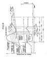
- An overall system of the slip control will be described herein with reference to FIG. 5 where reference symbols and figures have the following meanings:
- S/C: region of the slip control;
- E/G: slip control by the engine;
- B/R: slip control by the brake;
- F/B: feedback control
- 0/R: open loop control
- R/Y: recovery control
- B/A: backup control
- A/S: absorb (shockless) control
- S = 0.2: slip ratio at the time of commencement of the slip control (Ss)
- S = 0.17: target slip ratio by the brake (SBT)
- S = 0.09: slip ratio at the time of suspension (cancellation) of the slip control by the brake (Sac)
- S = 0. 06: target slip ratio by the engine (SET)
- S = 0.01-0.02: slip ratio in the region where the absorb control is effected
- S = ≦ 0.01: slip ratio in the region where the backup control is effected
- It is to be noted herein that the above figures are based on data obtained by actually driving a vehicle with spike tires on a frozen road surface. Furthermore, it is noted that the figures S=0.01-0.02 in the region where the absorb control is effected and the slip ratio S=0.09 at the time of suspension of the slip control by the brake are set as invariable, respectively, on the one hand, and that the target slip ratio SBT by the brake, the target slip ratio SET by the engine, and the slip ratio Ss at the time of commencement of the slip control vary with a state of road surfaces, on the other hand. In FIG. 5, the target slip ratio SBT by the brake, the target slip ratio SET by the engine, and the slip ratio Ss at the time of commencement of the slip control are set as 0.17, 0.06, and 0.2, respectively, as one example. It is also noted that the figure S=0.2 for the slip ratio at the time of commencement of the slip control uses a slip ratio at the time of the occurrence of the maximum grip force to be obtained when the spike tires were employed, as referred to as the solid line in FIG. 13. The reason why the slip ratio at the time of the commencement of the slip control is set as large as S=0.2 is so as to enable an actual slip ratio at the time when the maximum grip force is produced to be given. The target slip ratios SBT and SET by the engine and brake, respectively, are corrected in accordance with the slip ratio at the time of the occurrence of the maximum grip force. In FIG. 13, the solid line demonstrates a variation in the relationship of magnitudes of grip forces and transverse forces, represented as friction coefficients against road surfaces, during the use of spike tires with the corresponding slip ratios and the broken line demonstrates a variation in the relationship of magnitudes of grip and transverse forces, represented as friction coefficients against road surfaces, when normal tires are employed, with the corresponding slip ratios.
- Given the above description, FIG. 5 will be described in the course of time,
- No slip control is conducted over the course of time from to to t1 because the slip ratio S does not exceed S=0.2 that is the condition for the commencement of the slip control. In other words, when the spinning of the driving wheels is small, acceleration can be improved without the slip control, thereby enabling the driving utilizing a large grip force. It is a matter of course that, during this period of time, the peculiar character of the throttle opening against the accelerator opening is determined to be constant as demonstrated in FIG. 12.
- At this point t1 the slip control is commenced, and the slip ratio is equal to or higher than the point (S=0.09) of the suspension of the slip control by the brake. During the course of time, the slip ratio is so relatively large that the slip control is conducted by the decreasing generation of the torques by the engine and by the regulation by the brake. It is also noted that, since the target slip ratio (S=0.17) by the brake is higher than the target slip ratio (S=0.06) by the engine, brake pressures are applied to the brake when the spinning is large (S>0.17), on the one hand, and no brake pressures are applied thereto and the spinning is controlled so as to be reduced by the control of the engine only when the spinning is small (S<0.17). A description on the suspension of the slip control by the brake will be made below.
- During the course of a predetermined time (for example, 170 msec) after the reduction of the spinning (S<0.2), the
throttle valve 13 is retained at a predetermined opening (open loop control). At the point of S=0.2 2 (t2), the maximum acceleration GMAX is given, and the maximum road surface friction coefficient o (the maximum grip force of the driving wheels) is estimated from the maximum acceleration GMAX. Thethrottle valve 13 is retained for a predetermined period of time, as have been described above, so as to cause the driving wheels to produce the maximum grip forces. This control is carried out with the attempt to prevent the acceleration G of the vehicle body from being reduced immediately after the spinning reduced, that is, to prevent the overshoot from being occurred (as shown in FIG. 20), when a response of the feedback control is not in time because the rapid occurrence of the spinning reduction. If the reduction of the spinning is predicted, that is, when the slip ratio is decreased below S=0.2, a predetermined torque is secured in advance so as to improve the acceleration. The recovery control is particularly effective to avoid the excessive reduction in the slip ratio on account of a failure of the recovery control, leading to less acceleration or to avoid the re-occurrence of the spinning to a large extent by way of the excessive recovery control because the amount of the torques is increased in accordance with the occurrence of the spinning as shown in FIG. 15. It is noted herein that, although the maximum acceleration GMAX is the one obtained at the time of the commencement of the slip control, that is, at the time t, in FIG. 5, a maximum acceleration GMAX at the time when the spinning is being reduced as in this embodiment, that is, at the time t2 in FIG. 5, is said to reflect a state of road surfaces more accurately if it is used as an amount of the torques increased by the recovery control. - The optimum throttle opening Tvo for providing the driving wheels with torques capable of generating the maximum grip force can be theoretically given by a torque curve of the
engine 6 and a transmission gear ratio. In this embodiment, however, said Tvo is determined on the basis of a map, for example, as demonstrated in FIG. 15. The map is prepared in accordance with experimental procedures, in which GMAX is determined to become a constant value when it is equal to or lower than 0.15 or it is equal to or higher than 0.4 with measuring errors under consideration. It is to be noted here that, since the map indicated in FIG. 15 is prepared on the basis of a particular speed mode. such as, for example, the first speed mode, a map for any other speed mode can be prepared by correcting the optimum throttle opening Tvo. - The backup control is designed to be conducted (open loop control) in order to cope with an unusual reduction in the slip ratio S. That is, when the slip ratio S become lower than S=0.01, the feedback control is stopped and the opening of the
throttle valve 13 is caused to become larger in a stepwise manner. - When the slip ratio is between 0.01 and 0.02, that is, in the course of time from t4 to t5 and from te to t7, the absorb control is conducted so as to smoothly move to the next feedback control.
- The backup control is conducted when neither the feedback control nor the recovery control can work effectively. The backup control to be used here is designed so as to allow a response time to become sufficiently faster than the feedback control.
- A rate of the throttle opening in the backup control, in this embodiment, is designed so as to be increased for every 14 msec of the sampling time by 0.5% of the previous throttle opening.
- In the absorb control, as shown in FIG. 16, a throttle opening To is determined by proportionating a throttle opening T1 obtained by the operation of the backup control and a throttle opening T2 obtained by the operation of the feedback control with the present slip ratio So.
- By continuing the control conducted until the point t7, the control is caused to be transferred smoothly into the slip control by the engine alone.
- The slip control is suspended because the
accelerator 69 is fully closed by the operator D. At this time, there is no risk of the re-occurrence of the spinning, even if the throttle opening of thethrottle valve 13 is left in the discretion of the operator D, because the torques are caused to be decreased to a sufficient level. In this embodiment, the slip control is caused to be suspended, in addition to the full closure of theaccelerator 69, when the target throttle opening by the slip control becomes smaller than the throttle opening determined by FIG. 12 corresponding to the accelerator opening to be operated by the operator D. - It is noted herein that, in the course of transferring from a state where the slip control is conducted by both the engine and the brake to a state where the slip control is conducted by the engine alone, the slip control by the brake is suspended at the point t3. that is, at the point of the slip ratio being Ssc. Accordingly, the brake pressure is completely released and becomes zero after the point t3, as indicated in FIG. 19, so that the slip control is allowed to be conducted by the engine alone without any remaining influence from the brake. It is further noted herein that the brake pressure is caused to be sufficiently low in the course of transferring into the slip control by the engine alone because the target slip control SBT for the brake is set to be larger than the target slip ratio SET for the engine and the slip ratio SBC at the time of the brake release is set between the two target slip ratios, so that no spinning is likely to occur again at the time t3 when the brake is released. Merely for reference, it is noted that, if there were not set the point SBC where the braking is suspended, brake pressures are caused to remain in a region represented in FIG. 19 by the oblique lines after the point ts and the braking is still working thereafter.
- In accordance with the present invention, the overall slip control system will be described below with reference to FIGS. 6 to 11, inclusive. In this emobodimcnt, it should be noted that the control can be also made using the brake control to get free from the mud or the like - this control will be referred to herein as a so-called "stuck control". In the following description, reference symbol P denotes a step.
- In Pl, the system is initialized, and it is discriminated in P2 whether or not a vehicle is in a stuck state or whether or not it is stuck in the mud and consequently in an unmovable state. This discrimination is made by seeing whether or not a stuck flag is set as will be described below. If NO in P2, the flow proceeds to P3 and it is then discriminated whether or not the
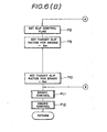
accelerator 69 is completely closed. If NO in P3, it is then discriminated in P4 whether or not the present throttle opening is larger than the accelerator opening. If it is discriminated as NO in P4, the flow proceeds to P5 and it is then discriminated whether or not it is in the progress of the slip control. This discrimination is conducted by checking whether or not a slip control flag is set. If NO in P5, it is discriminated in P6 whether or not the slip or spinning would have occurred to a degree such that the slip control was required. This is discriminated by seeing whether a slip flag for the leftfront wheel 2 and the right front wheel 3 is set. If it is discriminated NO in P6, the flow proceeds to P7 and the slip control is suspended, leading to the normal driving. - If YES in P6, the flow proceeds to P8 where a slip control flag is set. Then, in P9, the initial value (S=0.06 as in this embodiment) of the target slip ratio SET for the engine (throttle) is set and, in P10. the initial value (S=0.17 as in this embodiment) of the target slip ratio SBT for the brake is set. Thereafter, for the slip control, the brake control is effected in P11 and the engine control is done in P12, as will be described below. It is to be noted here that the determination of the initial values in both P9 and PIO is done on the basis of the maximum acceleration GMAX obtained by the previous slip control from the similar point of view as in P76 below.
- In P5, if it is discriminated as YES, the flow proceeds to Pll and the slip control continues to be done.
- If YES in P4, it is shown that no slip control is required and the flow advances to P14 where a slip control flag is reset. Then, the engine control is suspended in P15, and the brake control is conducted in P16. This brake control in P16 is done so as to cope with a state where a vehicle is stuck.
- In P3, if it is discriminated YES, the flow proceeds to P13 where the brake is released and treatments are done in P14 and thereafter.
- If YES in P2, the flow proceeds to P15 and the treatments following P15 are conducted.
- The flowchart demonstrated in FIG. 7 is designed so as to interrupt into the main flowchart demonstrated in FIG. 6. for example, in every 14 msec.
- In P21, signals from each of the
sensors 61 to 68, inclusive, are input for data treatments. The flow then proceeds to P22 and the treatment of slip detection is conducted, and then, in P23, the throttle control is conducted. - The throttle control in P23 is effected in accordance with a flowchart demonstrated in FIG. 8. In P24, it is discriminated whether or not a flag for the slip control is set, that is, whether or not the slip control is currently under way. If YES in P24, on the one hand, the
throttle valve 13 is controlled so as to select the control mode capable of reaching the predetermined target slip ratio SET for the slip control. that is, without following the peculiar character demonstrated in FIG. 12. If NO inP 24, on the other, the flow proceeds to P26 and the opening or closing of thethrottle valve 13 is regulated by the operator D in his discretion, leading to the peculiar character demonstrated in FIG. 2. Subsequent to P25 and P26, the control is carried out, in P27, to realize the target throttle opening, as will-be described below, that is, the control following P68, P70 and P71 and the control following the character of FIG.12 are conducted as will be described below. - The flowchart of FIG. 9 corresponds to P22 of FIG. 7 and is to detect whether or not the slip or spinning subject to the slip control has occurred and is to detect whether or not a vehicle is stuck.
- In P3I, it is discriminated whether or not the clutch 7 is completely connected. If YES in P31, it is found that the vehicle is not stuck. Then, the flow proceeds to P32 where a Stuck Flag is reset and, in P33, it is discriminated whether or not the present vehicle speed is as slow as, for example, below 6.3 km/h,
- If NO in P33, the flow proceeds to P33 where a correction value a for the slip detection is computed in accordance with a steered angle of the
steering wheel 70, as referred to in FIG. 14. Thereafter, in P35, it is discriminated whether or not a slip ratio for the leftfront wheel 2 as the lefthand driving wheel is larger than an addition of the above correction value a to the predetermined reference value of 0.2, that is, 0.2 + α. If YES in P35. on the one hand, it is found that the leftfront wheel 2 is in a state of slippage so that a slip flag is set in P36. If NO in P35, the flow proceeds to P37 where a slip flag for the leftfront wheel 2 is reset. It is noted here that the correction value a is determined with a difference of revolutions between the inner and outer wheels at the time of the spinning, particularly a difference of revolutions between the driving wheel and the leading wheel. - Subsequent to P36 and P37, a slip ratio for the right front wheel 3 is discriminated in P38 in substantially the same manner as described above on the left
front wheel 2. If YES in P38, a slip flag for the right front wheel 3 is set in P39 and, if NO in P38, a slip flag therefor is reset in P40. - When it is discriminated as YES in P33, the vehicle speed is so slow that the computation of the slip ratio based on the relationship (1) utilizing the vehicle speed is predicted to give high errors in measurement. Accordingly, in this case, a state of slippage is determined merely by the detection of the numbers of revolutions of the driving wheels. That is, in P41, it is discriminated whether or not the number of revolutions of the left
front wheel 2 is larger than that corresponding to the vehicle speed of 10 km/h. If YES in P41, a slip flag for the leftfront wheel 2 is set in P42 and, if NO in P41, a slip flag for the leftfront wheel 2 is reset. - After P42 and P43, a slip flag for the right front wheel 3 is set or reset in P44. P45 and P46 in substantially the same manner as in P41 to P43.
- In P31, if it is discriminated as NO, there is the possibility that the vehicle is stuck. In thi.s case, an operator D will try to get the vehicle free from the stuck state, as in the mud, with the clutch connected halfway. At this moment, the flow moves to P51 where it is discriminated whether or not a difference of the revolution numbers between the left and right
front wheels 2 and 3 as the driving wheels is small (is as large as, for example, 2 km/h, when the number of revolutions is translated into the vehicle speed). If NO in P51, it is discriminated in P52 whether or not the vehicle is currently in the progress of the stuck control. If NO in P52, it is discriminated in P53 whether or not the number of revolution of the right front wheel 3 is larger than the number of revolutions of the leftfront wheel 2. If YES in P53, it is discriminated in P54 whether or not the number of revolutions of the right front wheel 3 is larger than 1.5 times as much as the number of revolutions of the left front wheel 3. If YES in P54, on the one hand. a Stuck Flag is set in P56 and, if NO in P54, on the other hand, it is found that the vehicle is not stuck so that the treatments following P32, as described above, will be carried out. - If NO in P53, it is discriminated in P55 whether or not the number of revolutions of the left
front wheel 2 is larger than 1.5 times as much as the number of revolutions of the right front wheel 3. If YES in P55, the flow proceeds to P56 and, if NO in P55, the flow proceeds to P32. - After P56, it is discriminated in P57 whether or not the vehicle speed is faster than 6.3 km/h. If YES in P57, it is set in P58 such that the numbers of revolutions of the
front wheels 2 and 3 become 1.25 times as much as the numbers of revolutions of the respective leading wheels representing the vehicle speed equivalent to the slip ratio S=0.2. If NO in P57, the target numbers of revolutions of thefront wheels 2 and 3 are set to be equivalent each to the vehicle speed of 10 km/h in P59. - If YES in P51, the brake is released gradually in P60. If YES in P52, the flow proceeds directly to P56 without any treatment in P53, P54 and P55.
- The flowchart of FIG. 10 corresponds to P12 of FIG. 6.
- In P61, it is discriminated whether or not a state of the slip is moved into a reducing state, or whether the point t2 of FIG. 5 is passed. If NO in P61, it is discriminated in P62 whether or not the slip ratio of the left
front wheel 2 is larger than S=0.2, If NO in P62, it is discriminated in P63 whether or not the slip ratio of the right front wheel 3 is larger than S=0.2. If NO in P63, it is discriminated in P64 whether or not only one of the left and rightfront wheels 2 and 3 is under the brake control. viz., whether or not the vehicle is running on a split road. If YES in P64. on the one hand, the flow proceeds to P65 and the present slip ratio is set to the driving wheel with the lower slip ratio (select-low). If NO in P64. on the other hand, the flow proceeds to P66 and the present slip ratio is set to the driving wheel with the higher slip ratio (select-high). If YES in P62 and in P63, the flow proceeds to P66 in each case. - The select-high step in P66 is to enable the frequency of the braking to be lessened more by computing the present slip ratio in such a way that the slip or spinning of the driving wheel that is likely to slip more than the other driving wheel is controlled, The select-low step in P65 is to enable the slip or spinning of the driving wheel likely to slip more than the other to be controlled by the brake and, at the same time, to enable the vehicle to be driven using the grip force produced by the driving wheel that is less slippery, when the vehicle is running on a road such as a split road having different friction coefficients on road surfaces with which the left and right driving wheels are in contact. In the select-low step, it is preferred to limit its use, for example, to a particular period of time in order to avoid the excessive use of the brake or to provide backup means for suspending the select-low step in the event of the brake being overheated.
- After P65 or P66, it is discriminated in P67 whether or not the present slip ratio is larger than S=0.02, If YES in P67, the
throttle valve 13 is regulated for the slip control by way of the feedback control in P68. In this case, the target throttle opening Tn of thethrottle valve 13 is set to become the target slip ratio SET set in P9 or altered in P76 as will be described below. - If NO in P67, it is discriminated in P69 whether or not the present slip ratio is larger than S=0.01. If YES in P69, the flow proceeds to P70 and the absorb control is made as have been described above. If NO in P69, the backup control is done in P71, as have been described above.
- If f YES in P61. the flow proceeds to P72 where it t is s discriminated whether or not a predetermined period of time has passed after the slip reduced, viz., whether or not a period of time for the recovery control has passed - 170 msec in this embodiment. If NO in P72, the treatments following P73 are carried out to effect the recovery control. That is, in P73, the maximum acceleration GMAX of the automobile I is measured at the point t2 of FIG. 5 and, in P74, the optimum throttle opening Tvo capable of obtaining the maximum acceleration GMAX is set as shown in FIG. 15. Then, in P75. the optimum throttle opening Tvo obtained in P74 is corrected in accordance with the present speed mode of the
transmission 8. Since the torques applied to the driving wheels vary with the speed mode, it is noted in this embodiment that the optimum throttle opening Tvo is set in P74 for a reference speed mode and then in P75, the difference of the speed mode is corrected. Thereafter. in P76, the target slip ratio SET for the slip control by the engine (throttle) and the target slip ratio SBT for the slip control by the brake are altered by estimating a road surface friction coefficient from the maximum acceleration GMAX obtained in P73. Alteration of the target slip ratios SET and SBT will be described below. - If YES in P72, it is found that the recovery control is finished so that the flow proceeds to P62 for the further treatments as have been described.
- The flowchart of FIG. 11 corresponds to P11 and P12 of FIG. 6.
- It is discriminated in P81 whether or not the vehicle is stuck in the mud or the like. If NO in P81, the flow advances to P82 and the limit value (maximum value) BLM of a response speed Bn of the brake equivalent to the duty ratio for the opening or closing control of the valves SVl to SV4 is set as a function variable in accordance with a vehicle speed - a function becoming larger as the vehicle speed gets faster. If YES in P81, the limit value BLM is set in P83 to he a constant value smaller than the limit value BLM of P82. The treatments in P82 and P83 are arranged with the attempt unlikely to cause any vibration to occur on account of a speed of an increase or decrease in the brake pressure becoming too fast if the brake response speed Bn computed by the relationship (5) above is used as it is. In addition, it is particularly undesirable to cause the braking force on the driving wheels to vary rapidly in order to get the vehicle free from the stuck state so that the limit value BLM in P83 is set smaller than that in P82.
- After P82 or P83, it is discriminated in P84 whether or not the slip ratio is larger than S=0.09 that is the point of the brake control being suspended. If YES in P84, an operation speed Bn of the
brake 22 for the right front wheel is computed in P85, which is equivalent to Bn in the 1-PD control of FIG. 4. Thereafter, in P86, it is discriminated whether or not the operation speed Bn is larger than zero. This discrimination is to see whether or not the brake pressure is in the increasing direction by setting the direction of increasing the brake pressure to a positive value. viz., larger than zero, and the direction of decreasing the brake pressure to zero or a negative value smaller than zero. If YES in P86. it is discriminated in P87 whether or not Bn is larger than BLM. If YES in P86. on the one hand, Bn is set to the limit value BLM in P88 and then in P89, the brake pressure of theright brake 22 is increased. If NO in P87, the flow proceeds to P89 and the brake pressure thereof is increased in accordance with Bn set in P85. - When NO at P86, it is found that Bn is a negative value or zero so that Bn is converted in P90 to the corresponding absolute value followed by the treatments in P91 to P93, inclusive. The treatments in P91 to P93 are carried out to decrease the brake pressure of the
right brake 22 as in substantially the same manner as those in P87 to P89, inclusive. - If NO in P84, the flow proceeds to P95 and the brake control is suspended by the release of the brake.
- After P89, P93 or P95, the flow proceeds to P94 where the brake pressure of the
left brake 21 is increased or decreased in substantially the same manner as that of theright brake 22 is treated in P84 to P93, P95 inclusive. - It is noted herein that, if the difference between the actual revolution numbers and the target revolution numbers (an actual slip ratio and the target slip ratio) is large, the correction of the integral coefficient K1 in the above relationship (5), for example, is preferable in order to prevent the acceleration from being impaired by the excessive use of the brake and the engine from being stalled. This correction may be done by said K1 is caused to become smaller in a step between P85 and P86.
- In P76, the target slip ratio SET for the engine and SBT for the brake to be altered, as demonstrated in FIG. 17, on the basis of the maximum acceleration GMAX measured in P73. As apparent from FIG. 17, the slip ratios SET and SBT, as a rule, get larger as the maximum acceleration GMAX gets larger, and each of the limit value therefor is set.
- Notwithstanding the alteration of the target slip ratios SET and SBT, if a slip ratio SBC is set at the point of suspension of the slip control by the brake as an intermediate value between SET and SBT. the intermediate value SBC is not required, as a rule, to be altered. However, for example, if the intermediate value SBC is positioned in a constant distance at a position closer to the target slip ratio SET by 20% of a deviation value of the target slip ratios SET and SBT, the intermediate value See may be altered pursuant to the alterations of the target slip ratios SET and SHT.
- The following is a description on an influence of the determination of the target slip ratios SET and SBT on the driving of the
automobile 1. - The target slip ratios SET and SBT are offset as a whole in the upward or downward direction of FIG. 17. In order to make the grip force greater, they are offset in the upward direction. This can be said true as long as the slip ratio in the range of 0.2 to 0.3 or below is used because the road surface friction coefficient g is in the increasing direction up to the slip ratio being 0.2 to 0.3 as the peculiar character of spike tires, as shown in FIG. 13.
- The acceleration feeling varies with a difference between the target slip ratios SET and SBT. Acceleration is felt greater as the difference therebetween gets smaller. As in this embodiment, in instances where the target slip ratio SET for the engine is set smaller than the target slip ratio SBT for the brake, the brake control mainly works when the slip ratio of the driving wheel is larger and the engine control mainly works when the slip ratio of the driving wheel is smaller. Accordingly, if the difference between the target slip ratios SET and SBT is small, the engine control and the brake control work in a direction equally proportional to each other. That is, in this case the driving wheels arc driven in a state that the torques generated by the engine arc reduced by the brake so that the torques to be transmitted to the driving wheels are caused to be increased without a delay in a response merely by releasing the brake when the torques are required to be increased rapidly for acceleration.
- A smoothness in acceleration can be attained when the target slip ratio SBT for the brake gets large, viz., relatively large as compared to the target slip ratio SET for the engine. In this case, the engine control is caused to prevail over the brake control, thereby leading to the effective occurrence of a smooth variation in torques. which is the advantage of the engine control.
- A stability during the cornering can be obtained when the target slip ratio SET for the engine gets small, viz., relatively small compared to the target slip ratio SBT for the brake. As will be apparent from FIG. 13, in the region from S=0.2 to S=0.3 or below, where the maximum grip force is created, the reduction in the target slip ratio can make the grip forces of the driving wheels smaller and, at the same time, make the transverse force as large as possible.
- The characteristic modes as represented by (1) to (4) above, may be selected automatically or manually by the operator, D (mode selection).
- In the embodiments described above, the target slip ratio SBT for the brake is set larger than the target slip ratio SET for the engine so that no brake control is carried out when a degree of the slip or spinning is small, leading to a less frequency of uses of the brake, and that a barden of the brake control is lessened even when a large slip or spinning occurs. In addition, since there is set the intermediate point (SBC) between the target slip ratios SBT and SET, where the slip control by the brake is suspended, the brake pressure is caused to be decreased to a sufficient degree at the time of the suspension of the brake control so that a rapid variation in torques is caused unlikely to occur.
- FIG. 18 illustrates another embodiment in accordance with the present invention. In this embodiment, the target slip ratio SET for the engine is set to be equal to the target slip ratio SBT for the brake, and the slip ratio SBC at the time of the suspension of the brake control is set to be larger than the target slip ratios SET and SBT. Although this embodiment can simplify the way of control, the brake pressure at the time of the suspension of the brake control may be occasionally in a very high state.
- In accordance with the present invention, the embodiments have been described. but it should be understood that the present invention is by no means construed to be limited to the embodiments above and any changes or modifications as will be described below should be encompassed within the scope of the present invention.
- a. For the simplification of the control, the target slip ratio for the brake control may be set so as to be identical to the target slip ratio for the engine control, and the brake control may be designed to be conducted for a constant period of time after the commencement of the slip control, namely, after ti in FIG. 5.
- It is also possible that the target slip ratio for the brake control is set to be identical to the target slip ratio for the engine control and the brake control is carried out only when the slip or spinning of the driving wheels is being increased. That is, the brake control may be conducted when a variant of the revolution numbers of the driven wheels, dWD/dt, is positive or when a variant of the slip ratios, dS/dt. is positive.
- b. Means for adjusting the torque generated by the
engine 6 may be preferably of the type regulation a factor that exert the most influence upon the engine output. That is, it is preferred that the torque output is adjusted by a so-called load control. It is preferable to adjust an amount of a mixture fuel in the otto-type engine such as,for example, a gasoline engine, and to adjust an amount of a fuel injection in a diesel engine. - In addition to the load control, the ignition timing may be adjusted in the Otto-type engine, and the timing of the fuel injection may be adjusted in the diesel engine. In a supercharged engine, a supercharged pressure may be adjusted. Of course, a power source may include, in addition to an internal combustion engine, an electric motor. In this case, the output torque may be adjusted by the adjustment of an electric power to be supplied to the motor. It is also preferred that, for the adjustment of the output torque in the power-plant system, a state of connection of the clutch 7 or a transmission gear ratio of the
tranmission 8 as well as the engine may be adjusted. ln this case. a continuationaly variable transmission (CVT) is particularly preferred. - c. The
automobile 1 may include, in addition to the one with thefront wheels 2 and 3 as the driving wheels, the ones with therear wheels 4 and 5 as the driving wheels and with all the four wheels as the driving whee I s. - d. In order to detect a state of the slip or spinning of the driving wheels, it may be detected directly from the revolution numbers of the driving wheels as in this embodiment above and indirectly by predicting a state of the slip or spinning thereof from a state of the vehicle. Such a state of the vehicle may include, for example, an increase in the output torque of a power source or in the number of revolutions, a variation in the accelerator opening, a variation in the revolution of the driving shaft, a state of steering wheels (cornering), a state of the vehicle body lifted (acceleration), and a loadage. In addition to these factors, a road surface friction coefficient µ upon a magnitude of atmospheric temperatures, a rainfall, a snowfall or on an iced road may be detected automatically or input manually to predict a state of the slip or spinning of the driving wheels more adequately.
- e. The brake to be used for the slip control may be of the electromagnetic type as well as of the hydraulic type.
- f. In order to detect a state of the slip being reduced, a ratio of the slip ratios, dS/dt, may be used.
- g. As a state of the slip occurrence of the driving wheels to be used for determining an amount of the torque increased by the recovery control may be used, in addition to the maximum acceleration GMAX, for exampcl, a rotary acceleration of the driving wheels, a magnitude of the slip ratios of the driving wheels and a period of the slip continuance of the driving wheels.
- h. The hydraulic brake pressure regulating circuit in FIG. 2 and the
sensors 64. 65 and 66 may be composed of a known ABS (anti-brake lock system). - It is to be understood that the foregoing text and drawings relate to embodiments of the present invention given by way of examples but not limitation. Various other embodiments and variants are possible within the spirit and scope of the present invention.
Throttle Control
Claims (21)
Applications Claiming Priority (4)
| Application Number | Priority Date | Filing Date | Title |
|---|---|---|---|
| JP172698/86 | 1986-07-24 | ||
| JP17269886 | 1986-07-24 | ||
| JP61172703A JP2603226B2 (en) | 1986-07-24 | 1986-07-24 | Automotive slip control system |
| JP172703/86 | 1986-07-24 |
Publications (3)
| Publication Number | Publication Date |
|---|---|
| EP0254943A2 true EP0254943A2 (en) | 1988-02-03 |
| EP0254943A3 EP0254943A3 (en) | 1988-11-23 |
| EP0254943B1 EP0254943B1 (en) | 1993-03-10 |
Family
ID=26494968
Family Applications (1)
| Application Number | Title | Priority Date | Filing Date |
|---|---|---|---|
| EP87110079A Expired - Lifetime EP0254943B1 (en) | 1986-07-24 | 1987-07-13 | Vehicle slip control apparatus |
Country Status (3)
| Country | Link |
|---|---|
| US (1) | US4762196A (en) |
| EP (1) | EP0254943B1 (en) |
| DE (1) | DE3784577T2 (en) |
Cited By (10)
| Publication number | Priority date | Publication date | Assignee | Title |
|---|---|---|---|---|
| EP0272700A2 (en) * | 1986-12-23 | 1988-06-29 | Mazda Motor Corporation | Control apparatus for controlling device loaded on vehicle |
| WO1989004263A1 (en) * | 1987-11-06 | 1989-05-18 | Robert Bosch Gmbh | Drive slip regulating system |
| EP0336442A2 (en) * | 1988-04-07 | 1989-10-11 | Nissan Motor Co., Ltd. | Traction control system for automotive vehicle |
| EP0338588A2 (en) * | 1988-04-22 | 1989-10-25 | Honda Giken Kogyo Kabushiki Kaisha | Driving wheel torque control device for vehicle |
| EP0349993A2 (en) * | 1988-07-04 | 1990-01-10 | Mazda Motor Corporation | Slip control apparatus |
| GB2222703A (en) * | 1988-07-27 | 1990-03-14 | Mitsubishi Motors Corp | Traction control apparatus |
| EP0386792A2 (en) * | 1989-03-10 | 1990-09-12 | Mazda Motor Corporation | Slip control system for a vehicle |
| EP0408899A1 (en) * | 1989-06-23 | 1991-01-23 | Audi Ag | Traction-control system |
| EP0449118A2 (en) * | 1990-03-22 | 1991-10-02 | Mazda Motor Corporation | Slip control system for vehicle and rough road detecting system |
| EP0449333A2 (en) * | 1990-03-30 | 1991-10-02 | Mazda Motor Corporation | Slip control system for automotive vehicle |
Families Citing this family (43)
| Publication number | Priority date | Publication date | Assignee | Title |
|---|---|---|---|---|
| DE3540708A1 (en) * | 1985-11-16 | 1987-05-21 | Bosch Gmbh Robert | DRIVE CONTROL SYSTEM |
| DE3634240A1 (en) * | 1986-10-08 | 1988-04-21 | Bosch Gmbh Robert | DRIVE SLIP CONTROL DEVICE |
| DE3644137A1 (en) * | 1986-12-23 | 1988-07-14 | Daimler Benz Ag | DEVICE FOR CONTROLLING AT LEAST ONE SIZE INFLUENCING THE DRIVE TORQUE OF AN INTERNAL COMBUSTION ENGINE OF A MOTOR VEHICLE |
| JP2508093B2 (en) * | 1987-06-01 | 1996-06-19 | 日本電装株式会社 | Vehicle slip control device |
| JPH0623029B2 (en) * | 1987-07-30 | 1994-03-30 | マツダ株式会社 | Anti-slip device for vehicle with automatic transmission |
| JPH01155038A (en) * | 1987-12-10 | 1989-06-16 | Honda Motor Co Ltd | Driving wheel slip controller |
| JP2605089B2 (en) * | 1988-03-23 | 1997-04-30 | 本田技研工業株式会社 | Excessive slip control of drive wheels |
| US4926333A (en) * | 1988-04-20 | 1990-05-15 | Mitsubishi Jidosha Kogyo Kabushiki Kaisha | Traction control apparatus |
| US5255193A (en) * | 1988-05-12 | 1993-10-19 | Nissan Motor Company | Traction control system for controlling engine output and brake for maintaining optimum wheel traction with road friction level dependent brake control |
| JPH0238150A (en) * | 1988-07-29 | 1990-02-07 | Mazda Motor Corp | Slip controller for automobile |
| US4916618A (en) * | 1988-09-12 | 1990-04-10 | General Motors Corporation | Vehicle traction controller |
| US5079708A (en) * | 1989-03-24 | 1992-01-07 | Brown Jack L | Road vehicle cornering assistance mechanism |
| JPH0333553A (en) * | 1989-06-29 | 1991-02-13 | Mazda Motor Corp | Slip control device for vehicle |
| US5172319A (en) * | 1989-11-13 | 1992-12-15 | Honda Giken Kogyo Kabushiki Kaisha | Drive wheel slip control system for vehicle |
| JP2832281B2 (en) * | 1989-12-28 | 1998-12-09 | 富士重工業株式会社 | Transmission control device for continuously variable transmission |
| US5009294A (en) * | 1990-01-19 | 1991-04-23 | General Motors Corporation | Vehicle traction control system |
| JPH0455156A (en) * | 1990-06-21 | 1992-02-21 | Mazda Motor Corp | Traction control device for vehicle |
| JP2902059B2 (en) * | 1990-06-21 | 1999-06-07 | マツダ株式会社 | Vehicle traction control device |
| JP2935379B2 (en) * | 1991-02-14 | 1999-08-16 | マツダ株式会社 | Vehicle slip control device |
| US5431241A (en) * | 1994-05-31 | 1995-07-11 | Zexel-Gleason Usa, Inc. | Hybrid traction control system |
| US5524080A (en) * | 1994-11-22 | 1996-06-04 | Zexel Torsen Inc. | Traction control with variable threshold |
| US5711024A (en) | 1994-11-25 | 1998-01-20 | Itt Automotive Europe Gmbh | System for controlling yaw moment based on an estimated coefficient of friction |
| US5732379A (en) | 1994-11-25 | 1998-03-24 | Itt Automotive Europe Gmbh | Brake system for a motor vehicle with yaw moment control |
| US5710705A (en) | 1994-11-25 | 1998-01-20 | Itt Automotive Europe Gmbh | Method for determining an additional yawing moment based on side slip angle velocity |
| US5694321A (en) | 1994-11-25 | 1997-12-02 | Itt Automotive Europe Gmbh | System for integrated driving stability control |
| DE19515055A1 (en) | 1994-11-25 | 1996-05-30 | Teves Gmbh Alfred | Motor-vehicle ride stability regulator with speed-dependent model choice |
| US5742507A (en) | 1994-11-25 | 1998-04-21 | Itt Automotive Europe Gmbh | Driving stability control circuit with speed-dependent change of the vehicle model |
| US5774821A (en) | 1994-11-25 | 1998-06-30 | Itt Automotive Europe Gmbh | System for driving stability control |
| US5732378A (en) | 1994-11-25 | 1998-03-24 | Itt Automotive Europe Gmbh | Method for determining a wheel brake pressure |
| US5732377A (en) | 1994-11-25 | 1998-03-24 | Itt Automotive Europe Gmbh | Process for controlling driving stability with a yaw rate sensor equipped with two lateral acceleration meters |
| US5710704A (en) | 1994-11-25 | 1998-01-20 | Itt Automotive Europe Gmbh | System for driving stability control during travel through a curve |
| US5701248A (en) | 1994-11-25 | 1997-12-23 | Itt Automotive Europe Gmbh | Process for controlling the driving stability with the king pin inclination difference as the controlled variable |
| JP3111401B2 (en) * | 1994-12-16 | 2000-11-20 | 本田技研工業株式会社 | Vehicle total grip force estimation device and vehicle slip control device |
| US5671144A (en) * | 1995-05-01 | 1997-09-23 | Zexel Torsen Inc. | Combined power limiting and power distributing traction control system for improving vehicle performance in turns |
| US6193464B1 (en) | 1998-12-02 | 2001-02-27 | Mcdonnell Douglas Helicopter Company, | Active brake control for rotor/wing aircraft |
| EP1118517B1 (en) * | 1999-12-30 | 2011-03-16 | Robert Bosch Gmbh | Vehicle brake system |
| CN101765726B (en) * | 2007-05-30 | 2015-04-15 | 株式会社小松制作所 | Driving force controller and driving force control method of working vehicle |
| US8170767B2 (en) | 2007-10-30 | 2012-05-01 | Ford Global Technologies, Llc | Vehicle stability control system and method |
| US8532884B2 (en) * | 2008-03-21 | 2013-09-10 | Komatsu Ltd. | Engine-driven machine, control device for engine-driven machine, and method for controlling maximum output characteristic of engine |
| CA2717031C (en) | 2008-06-25 | 2014-05-13 | Asahi Kasei Fibers Corporation | Elastic signal transmission cable |
| GB2505668B (en) | 2012-09-06 | 2017-04-12 | Jaguar Land Rover Ltd | Vehicle recovery system |
| US20150239475A1 (en) * | 2014-02-21 | 2015-08-27 | Ford Global Technologies, Llc | Hybrid vehicle and method of operation |
| WO2016042856A1 (en) * | 2014-09-18 | 2016-03-24 | ジヤトコ株式会社 | Vehicle control device and vehicle control method |
Citations (8)
| Publication number | Priority date | Publication date | Assignee | Title |
|---|---|---|---|---|
| US4484280A (en) * | 1981-07-10 | 1984-11-20 | Daimler-Benz Aktiengesellschaft | System for controlling the propulsion on motor vehicles |
| EP0126051A2 (en) * | 1983-05-10 | 1984-11-21 | Volvo Flygmotor Ab | Method and device for preventing slipping and/or skidding between driveable and breakable wheels and the supporting surface in vehicle traction systems |
| DE3416292A1 (en) * | 1984-05-03 | 1985-11-07 | Bosch Gmbh Robert | CONTROL CIRCUIT FOR THE DRIVED WHEELS OF A VEHICLE |
| DE3419716A1 (en) * | 1984-05-26 | 1985-11-28 | Robert Bosch Gmbh, 7000 Stuttgart | DRIVE CONTROL SYSTEM |
| EP0166258A1 (en) * | 1984-06-22 | 1986-01-02 | Robert Bosch Gmbh | Antiskid control system |
| DE3435869A1 (en) * | 1984-09-29 | 1986-04-10 | Robert Bosch Gmbh, 7000 Stuttgart | DRIVE CONTROL SYSTEM |
| US4583611A (en) * | 1983-08-31 | 1986-04-22 | Robert Bosch Gmbh | Wheel spin prevention system |
| EP0180095A2 (en) * | 1984-10-30 | 1986-05-07 | Toyota Jidosha Kabushiki Kaisha | Wheel slip controlling system for a vehicle |
Family Cites Families (1)
| Publication number | Priority date | Publication date | Assignee | Title |
|---|---|---|---|---|
| JPS6160331A (en) * | 1984-09-03 | 1986-03-28 | Toyota Motor Corp | Vehicle slip controller |
-
1987
- 1987-07-13 DE DE8787110079T patent/DE3784577T2/en not_active Expired - Fee Related
- 1987-07-13 EP EP87110079A patent/EP0254943B1/en not_active Expired - Lifetime
- 1987-07-17 US US07/074,783 patent/US4762196A/en not_active Expired - Lifetime
Patent Citations (8)
| Publication number | Priority date | Publication date | Assignee | Title |
|---|---|---|---|---|
| US4484280A (en) * | 1981-07-10 | 1984-11-20 | Daimler-Benz Aktiengesellschaft | System for controlling the propulsion on motor vehicles |
| EP0126051A2 (en) * | 1983-05-10 | 1984-11-21 | Volvo Flygmotor Ab | Method and device for preventing slipping and/or skidding between driveable and breakable wheels and the supporting surface in vehicle traction systems |
| US4583611A (en) * | 1983-08-31 | 1986-04-22 | Robert Bosch Gmbh | Wheel spin prevention system |
| DE3416292A1 (en) * | 1984-05-03 | 1985-11-07 | Bosch Gmbh Robert | CONTROL CIRCUIT FOR THE DRIVED WHEELS OF A VEHICLE |
| DE3419716A1 (en) * | 1984-05-26 | 1985-11-28 | Robert Bosch Gmbh, 7000 Stuttgart | DRIVE CONTROL SYSTEM |
| EP0166258A1 (en) * | 1984-06-22 | 1986-01-02 | Robert Bosch Gmbh | Antiskid control system |
| DE3435869A1 (en) * | 1984-09-29 | 1986-04-10 | Robert Bosch Gmbh, 7000 Stuttgart | DRIVE CONTROL SYSTEM |
| EP0180095A2 (en) * | 1984-10-30 | 1986-05-07 | Toyota Jidosha Kabushiki Kaisha | Wheel slip controlling system for a vehicle |
Cited By (20)
| Publication number | Priority date | Publication date | Assignee | Title |
|---|---|---|---|---|
| EP0272700A3 (en) * | 1986-12-23 | 1989-02-22 | Mazda Motor Corporation | Control apparatus for controlling device loaded on vehicle |
| EP0272700A2 (en) * | 1986-12-23 | 1988-06-29 | Mazda Motor Corporation | Control apparatus for controlling device loaded on vehicle |
| WO1989004263A1 (en) * | 1987-11-06 | 1989-05-18 | Robert Bosch Gmbh | Drive slip regulating system |
| EP0336442A3 (en) * | 1988-04-07 | 1990-09-19 | Nissan Motor Co., Ltd. | Traction control system for automotive vehicle |
| EP0336442A2 (en) * | 1988-04-07 | 1989-10-11 | Nissan Motor Co., Ltd. | Traction control system for automotive vehicle |
| EP0338588A2 (en) * | 1988-04-22 | 1989-10-25 | Honda Giken Kogyo Kabushiki Kaisha | Driving wheel torque control device for vehicle |
| EP0338588A3 (en) * | 1988-04-22 | 1992-03-11 | Honda Giken Kogyo Kabushiki Kaisha | Driving wheel torque control device for vehicle |
| EP0349993A2 (en) * | 1988-07-04 | 1990-01-10 | Mazda Motor Corporation | Slip control apparatus |
| EP0349993A3 (en) * | 1988-07-04 | 1991-05-22 | Mazda Motor Corporation | Slip control apparatus |
| US4985837A (en) * | 1988-07-27 | 1991-01-15 | Mitsubishi Jidosha Kogyo Kabushiki Kaisha | Traction control apparatus |
| GB2222703A (en) * | 1988-07-27 | 1990-03-14 | Mitsubishi Motors Corp | Traction control apparatus |
| GB2222703B (en) * | 1988-07-27 | 1992-08-05 | Mitsubishi Motors Corp | Traction control apparatus |
| EP0386792A2 (en) * | 1989-03-10 | 1990-09-12 | Mazda Motor Corporation | Slip control system for a vehicle |
| EP0386792A3 (en) * | 1989-03-10 | 1991-08-28 | Mazda Motor Corporation | Slip control system for a vehicle |
| EP0408899A1 (en) * | 1989-06-23 | 1991-01-23 | Audi Ag | Traction-control system |
| EP0449118A2 (en) * | 1990-03-22 | 1991-10-02 | Mazda Motor Corporation | Slip control system for vehicle and rough road detecting system |
| EP0449118A3 (en) * | 1990-03-22 | 1992-05-27 | Mazda Motor Corporation | Slip control system for vehicle and rough road detecting system |
| EP0655362A3 (en) * | 1990-03-22 | 1995-07-05 | Mazda Motor | |
| EP0449333A2 (en) * | 1990-03-30 | 1991-10-02 | Mazda Motor Corporation | Slip control system for automotive vehicle |
| EP0449333A3 (en) * | 1990-03-30 | 1993-01-27 | Mazda Motor Corporation | Slip control system for automotive vehicle |
Also Published As
| Publication number | Publication date |
|---|---|
| EP0254943A3 (en) | 1988-11-23 |
| DE3784577D1 (en) | 1993-04-15 |
| EP0254943B1 (en) | 1993-03-10 |
| US4762196A (en) | 1988-08-09 |
| DE3784577T2 (en) | 1993-06-17 |
Similar Documents
| Publication | Publication Date | Title |
|---|---|---|
| US4762196A (en) | Vehicle slip control apparatus | |
| US4779696A (en) | Vehicle slip control apparatus | |
| US4884651A (en) | Vehicle slip control apparatus | |
| US4825367A (en) | Control apparatus for controlling device loaded on vehicle | |
| JP2537807B2 (en) | Automotive slip control system | |
| JP2621858B2 (en) | Automotive slip control system | |
| JP2502981B2 (en) | Vehicle slip control device | |
| JP2512718B2 (en) | Automotive slip control system | |
| JP2677392B2 (en) | Vehicle slip control device | |
| JP2587041B2 (en) | Automotive slip control system | |
| JP2502983B2 (en) | Vehicle slip control device | |
| JP2603226B2 (en) | Automotive slip control system | |
| JP2540520B2 (en) | Automotive slip control system | |
| JP2593477B2 (en) | Automotive slip control device | |
| JP2512720B2 (en) | Automotive slip control system | |
| JP2512719B2 (en) | Automotive slip control system | |
| JP2693148B2 (en) | Automotive slip control system | |
| JP2502984B2 (en) | Vehicle slip control device | |
| JP2603227B2 (en) | Automotive slip control system | |
| JP2502994B2 (en) | Vehicle slip control device | |
| JP2502993B2 (en) | Vehicle slip control device | |
| JPH0790718B2 (en) | Automotive slip control device | |
| JP2502982B2 (en) | Vehicle slip control device | |
| JPH089305B2 (en) | Automotive slip control device | |
| JP2610835B2 (en) | Automotive slip control system |
Legal Events
| Date | Code | Title | Description |
|---|---|---|---|
| PUAI | Public reference made under article 153(3) epc to a published international application that has entered the european phase |
Free format text: ORIGINAL CODE: 0009012 |
|
| AK | Designated contracting states |
Kind code of ref document: A2 Designated state(s): DE FR GB |
|
| PUAL | Search report despatched |
Free format text: ORIGINAL CODE: 0009013 |
|
| AK | Designated contracting states |
Kind code of ref document: A3 Designated state(s): DE FR GB |
|
| 17P | Request for examination filed |
Effective date: 19890315 |
|
| 17Q | First examination report despatched |
Effective date: 19910730 |
|
| GRAA | (expected) grant |
Free format text: ORIGINAL CODE: 0009210 |
|
| AK | Designated contracting states |
Kind code of ref document: B1 Designated state(s): DE FR GB |
|
| REF | Corresponds to: |
Ref document number: 3784577 Country of ref document: DE Date of ref document: 19930415 |
|
| ET | Fr: translation filed | ||
| PLBE | No opposition filed within time limit |
Free format text: ORIGINAL CODE: 0009261 |
|
| STAA | Information on the status of an ep patent application or granted ep patent |
Free format text: STATUS: NO OPPOSITION FILED WITHIN TIME LIMIT |
|
| 26N | No opposition filed | ||
| PGFP | Annual fee paid to national office [announced via postgrant information from national office to epo] |
Ref country code: GB Payment date: 19960704 Year of fee payment: 10 |
|
| PGFP | Annual fee paid to national office [announced via postgrant information from national office to epo] |
Ref country code: FR Payment date: 19960709 Year of fee payment: 10 |
|
| PG25 | Lapsed in a contracting state [announced via postgrant information from national office to epo] |
Ref country code: GB Free format text: LAPSE BECAUSE OF NON-PAYMENT OF DUE FEES Effective date: 19970713 |
|
| GBPC | Gb: european patent ceased through non-payment of renewal fee |
Effective date: 19970713 |
|
| PG25 | Lapsed in a contracting state [announced via postgrant information from national office to epo] |
Ref country code: FR Free format text: LAPSE BECAUSE OF NON-PAYMENT OF DUE FEES Effective date: 19980331 |
|
| REG | Reference to a national code |
Ref country code: FR Ref legal event code: ST |
|
| PGFP | Annual fee paid to national office [announced via postgrant information from national office to epo] |
Ref country code: DE Payment date: 20030724 Year of fee payment: 17 |
|
| PG25 | Lapsed in a contracting state [announced via postgrant information from national office to epo] |
Ref country code: DE Free format text: LAPSE BECAUSE OF NON-PAYMENT OF DUE FEES Effective date: 20050201 |