EP0255031A2 - Method of controlling dot gain on proof print - Google Patents
Method of controlling dot gain on proof print Download PDFInfo
- Publication number
- EP0255031A2 EP0255031A2 EP87110599A EP87110599A EP0255031A2 EP 0255031 A2 EP0255031 A2 EP 0255031A2 EP 87110599 A EP87110599 A EP 87110599A EP 87110599 A EP87110599 A EP 87110599A EP 0255031 A2 EP0255031 A2 EP 0255031A2
- Authority
- EP
- European Patent Office
- Prior art keywords
- printing
- dot gain
- proof
- velocity
- press
- Prior art date
- Legal status (The legal status is an assumption and is not a legal conclusion. Google has not performed a legal analysis and makes no representation as to the accuracy of the status listed.)
- Withdrawn
Links
Images
Classifications
-
- B—PERFORMING OPERATIONS; TRANSPORTING
- B41—PRINTING; LINING MACHINES; TYPEWRITERS; STAMPS
- B41F—PRINTING MACHINES OR PRESSES
- B41F3/00—Cylinder presses, i.e. presses essentially comprising at least one cylinder co-operating with at least one flat type-bed
- B41F3/18—Cylinder presses, i.e. presses essentially comprising at least one cylinder co-operating with at least one flat type-bed of special construction or for particular purposes
- B41F3/28—Proof-print presses for relief printing, lithography or intaglio printing, i.e. presses for checking accuracy of printing surfaces
-
- B—PERFORMING OPERATIONS; TRANSPORTING
- B41—PRINTING; LINING MACHINES; TYPEWRITERS; STAMPS
- B41F—PRINTING MACHINES OR PRESSES
- B41F33/00—Indicating, counting, warning, control or safety devices
- B41F33/0036—Devices for scanning or checking the printed matter for quality control
Definitions
- the present invention relates generally to proofing with ink by a proof press, and particularly to a method of controlling so-called dot gain (this word means the undesirable printing of dots as larger areas than their actual size, which is also called “dot spread” or “dot enlargement) on a proof print produced by a proof press.
- halftone dots are generally apt to spread undesirably as larger areas than their actual size on a printing plate, when a printing plate bearing an image of halftone dots thereon is used in a production press.
- the amount of such dot gain is much smaller in highlight dots, but is larger in middle tones to deep tones.
- a print produced by a production press should be produced so as to approach a proof print produced by a proof press, since the proof print is to be an original of printing on a production press.
- the publication shows several methods for resolving such dot gain effects as follows.
- a print produced by the proof press is produced so as to approach a print produced by the production press.
- appropriate printing conditions on the production press must be determined before proof printing on the proof press is carried out.
- Such printing conditions will be determined on the basis of a printing pressure, an ink viscosity, an atomospheric temperature, humidity and so on, by taking account of various factors peculiar to printing on the production press, e.g. trapping, dot gain, printing stability, image density and so on.
- an object of the present invention is to provide a novel method of controlling dot gain on a proof print effectively and easily.
- the aforementioned object is accomplished by the present invention, with a method of controlling dot gain on proof print which includes the steps of: previously printing an object to be proofed including a control patch at different velocities, to obtain proof prints; obtaining dot gain values in respective prints; inputting said dot gain values to a memory of a proof press to be used for proof printing; calculating on the basis of said dot gain values and the printing velocities at which the previous printing is carried out; obtaining at least one approximate expression representing the relationship between the printing velocity and the dot gain value; inputting a desired dot gain value; obtaining an actual printing velocity corresponding to said desired dot gain value on the basis of said approximate expression; and carrying out an actual proof printing of the object at the actual printing velocity.
- the proof press generally comprises a horizontal base frame 1 and a carriage 3 movable horizontally along the base frame 1 by a motor 31 mechanically connected thereto.
- the base frame 1 includes a plate bed 5 on which a . desired proof plate 9 is mounted and a paper bed 7 on which a sheet paper 11 to be printed is mounted.
- a damping mechanism 13 is provided, which mechanism 13 includes a pair of damping rollers by which an appropriate amount of damping water is supplied to the surface of the proof plate 9.
- an inking mechanism 15 including a plurality of inking rollers 29, by which an appropriate amount of a desired ink is supplied to the surface of the proof plate 9.
- the carriage 3 comprises within a housing 17 a damping mechanism 19 including a plurality of damping rollers 21, art inking mechanism 23 including a plurality of inking rollers 25 and a blanket cylinder 27. All these mechanisms and the cylinder are movable vertically, and the damping mechanism 19 is engaged with the damping mechanism 13 provided on the base frame 1 when the carriage 3 is moved up to the left end position, whereby an appropriate amount of damping water is transferred to and held by the damping rollers 21 of the damping mechanism 19, then the damping water thus transferred and held is supplied to the entire surface of the proof plate 9 as the carriage 3 travels rightwards along the base frame 1.
- the carriage 3 rests at the right end portion of the base frame 1, at which the inking rollers 29 are engaged with the rollers 25 of the inking mechanism 23.
- a desired ink to be used for proof printing is supplied to the rollers 29 and is transferred to and kneaded by the inking mechanism 23 including rollers 25.
- the ink thus transferred and kneaded is supplied to the entire surface of the proof plate 9 mounted on the plate bed 5 as the carriage 3 travels leftwards along the base frame 1.
- the carriage 3 After that, the carriage 3 returns to travel rightwards, and the inking mechanism 23 is lifted not to contact with the proof plate 9 nor the paper sheet 11. Simultaneously, the blanket cylinder 27 is lowered to contact with and rotate on the proof plate 9, whereby ink of the image is transferred to the peripheral surface of the blanket 27, and is in turn transferred to the surface of the sheet paper 11 as the carriage 3 travels rightwards.
- the carriage 3 reciprocates on the base frame 1 by means of the motor 31, by which a desired number of proof prints can be obtained.
- the control circuit 41 comprises a central processing unit (CPU) 43 including a processing section 45 and a controlling section 47, a random access memory (RAM) 49, which is connected to the CPU 43, including a memory for measured data 51, a memory for designated data 53, a memory for approximate expressions 55 and a memory for printing velocity 57.
- the controlling circuit 41 further comprises a read only memory (ROM) 59 connected to the CPU 47 and an input-output unit 61 connected also to the CPU 43 respectively.
- ROM read only memory
- ROM 59 there stored four kinds of standard velocity of the carriage 3 including the highest and lowest ones. Stored is also functional data, e.g. in the form of a simple equation:
- the control circuit 41 is connected to a driving control unit 63 through a digital-analog convertor 59 and an ' amplifier 61, and the driving control unit 63 is in turn connected to the motor 31.
- the driving unit 63 controls the rotation of the motor 31 on the basis of a signal outputted from the input-output unit 61.
- a keyboard 67 is connected to the control circuit 41 through an interface 65. As shown by broken lines, it may be possible to connect a densitometer 69 to the interface 65 either directly or through keyboard 67 by an operator.
- a proof print produced by the proof press is measured by the densitometer 69, and the density value measured by it is inputted to the input-output unit 61 either directly or through the keyboard 67 by an operator.
- the highest velocity Vb is read out from the ROM 59, the carriage 3 is moved at the velocity Vb by means of the motor 31, whereby producing another proof print.
- the density of the control strip of the proof print is measured by the densitometer 69 in the same manner as above, to obtain the dot gain value D b.
- the measured value of dot gain Db is inputted to the memory 51 of the RAM 49 through the keyboard 67.
- a point A denotes the measured value of dot gain when the proof printing is carried out at the lowest velocity Va
- a point B denotes the measured value of dot gain when the proof printing is carried out at the highest velocity Vb.
- the functional data is to connect both points A and B by an appropriate curve or line, which will be changed on the conditions under which proof printing is carried out.
- the moving velocity of the carriage 3 was set at 0.3 m/sec. as the lowest printing velocity Va. Proof printing was made under the conditions that the solid ink density be maintained at 1.60, to obtain ten prints with that velocity.
- the density area of a 50% screen patch of a control strip of respective prints was measured by the densitometer, to obtain density values. Then, respective density values were substituted to the Murray Davis' equation:
- the moving velocity of the carriage 3 was set at 0.4 m/sec., 0.5 m/sec. and 0.6 m/sec. respectively, and the average dot gain values at the respective velocities were obtained, which are listed in Table 1.
- the second example was also carried out under the same conditions as the first example.
- the functional data stored in the ROM 59 was in the form of a cubic equation:
- the relationship between the printing velocity and the dot gain value is represented as a curve shown in Fig. 6.
- the approximate expression is stored in the memory 55.
- the desired printing velocity is read out from the memory 57, which is outputted to the driving unit 63 through the digital-analog convertor 59 and the amplifier 61.
- the motor 31 is driven under the control of the driving unit 63, and accordingly the carriage 3 moves at the corresponding velocity, whereby desired amount of dot gain can be obtained.
- Example 1 the approximate expression is represented as a kinked line, it may be obtained by interpolation on the basis of the respective points of the highest and lowest velocities and intermediate points therebetween.
- Example 1 the approximate expression is obtained on the basis of four kinds of printing velocities, it can be done on the basis of only the highest and lowest printing velocities velocity.
- the amount of dot gain is obtained by measuring the halftone density of a control strip, but it may be applicable that, instead of measurement by the densitometer, the dot gain value is directly obtained by a dot-gain meter, or that comparative contrast value K expressed by the formula: . is used instead of the dot gain value.
- any value convertable to the dot gain value can be available in the method according to the invention.
Abstract
Description
- Method of Controlling Dot Gain on Proof Print
- The present invention relates generally to proofing with ink by a proof press, and particularly to a method of controlling so-called dot gain (this word means the undesirable printing of dots as larger areas than their actual size, which is also called "dot spread" or "dot enlargement) on a proof print produced by a proof press.
- It is well known that, during offset process, halftone dots are generally apt to spread undesirably as larger areas than their actual size on a printing plate, when a printing plate bearing an image of halftone dots thereon is used in a production press. The amount of such dot gain is much smaller in highlight dots, but is larger in middle tones to deep tones.
- It is also well known that, in comparison with prints . produced by a production press and a proof press, dot gain of the halftone dots on the print produced by the proof press is generally less, though it is apt to occur. On the other hand, dot gain on the print produced by the production press is widely spread relative to the actual dot size of a printing plate.
- Such difference in the amount of dot gain between on a proof press and on a production press raises serious problems.
- There disclosed several known techniques in the publication "PHOTOMECHANICS HANDBOOK", 1980, pp. 128-130, (published by Japan Association of Graphic Arts Technology).
- According to the publication, it is commonly considered that a print produced by a production press should be produced so as to approach a proof print produced by a proof press, since the proof print is to be an original of printing on a production press. However, it will be impossible to reduce the amount of dot gain in printing on the production press up to such amount of dot gain as on the proof press, for the reasons that printing on the production press is produced at a very high velocity in comparison with printing on the proof press, that a printing pressure on the production press is different from one on the proof press, and so on. Thus, the publication shows several methods for resolving such dot gain effects as follows.
- It has been generally adopted that the dot size of a printing plate for use in printing on the production press is reduced in comparison with that of a proof plate, whereby the amount of dot gain on the production press is cancelled out, so that the resultant dot size of the print produced by the production press is consistent with that of the proof print produced by the proof press.
- Another method is that a print produced by the proof press is produced so as to approach a print produced by the production press. In this case, appropriate printing conditions on the production press must be determined before proof printing on the proof press is carried out. Such printing conditions will be determined on the basis of a printing pressure, an ink viscosity, an atomospheric temperature, humidity and so on, by taking account of various factors peculiar to printing on the production press, e.g. trapping, dot gain, printing stability, image density and so on.
- These methods conventionally adopted relies upon the operator's ripe experience and requires an operator to be well acquainted with such operations.
- Accordingly, an object of the present invention is to provide a novel method of controlling dot gain on a proof print effectively and easily.
- The aforementioned object is accomplished by the present invention, with a method of controlling dot gain on proof print which includes the steps of: previously printing an object to be proofed including a control patch at different velocities, to obtain proof prints; obtaining dot gain values in respective prints; inputting said dot gain values to a memory of a proof press to be used for proof printing; calculating on the basis of said dot gain values and the printing velocities at which the previous printing is carried out; obtaining at least one approximate expression representing the relationship between the printing velocity and the dot gain value; inputting a desired dot gain value; obtaining an actual printing velocity corresponding to said desired dot gain value on the basis of said approximate expression; and carrying out an actual proof printing of the object at the actual printing velocity.
- Other novel features and advantages of the invention will become apparent in the course of the following detailed description taken together with the accompanying drawings, which are directed only to the understanding of the present invention and not to the restriction of the scope of the invention.
-
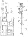
- Fig. 1 shows a block diagram of a controlling circuit for controlling dot gain;
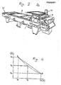
- Fig. 2 shows a perspective view of a proof press;
- Fig. 3 shows a schematic sectional view of a proof press shown in Fig. 2; and
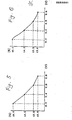
- Figs. 4 through 6 respectively shows a graph which represents the relationship between the dot gain value and the printing velocity.
- Referring to Figs. 2 and 3, which show a perspective view of a proof press to be used and a schematic view thereof respectively, the proof press generally comprises a
horizontal base frame 1 and acarriage 3 movable horizontally along thebase frame 1 by a motor 31 mechanically connected thereto. - The
base frame 1 includes aplate bed 5 on which a . desired proof plate 9 is mounted and a paper bed 7 on which a sheet paper 11 to be printed is mounted. At the left end of the base frame adamping mechanism 13 is provided, whichmechanism 13 includes a pair of damping rollers by which an appropriate amount of damping water is supplied to the surface of the proof plate 9. At the other end of thebase frame 1 there provided aninking mechanism 15 including a plurality ofinking rollers 29, by which an appropriate amount of a desired ink is supplied to the surface of the proof plate 9. - The
carriage 3 comprises within a housing 17 adamping mechanism 19 including a plurality ofdamping rollers 21,art inking mechanism 23 including a plurality ofinking rollers 25 and ablanket cylinder 27. All these mechanisms and the cylinder are movable vertically, and thedamping mechanism 19 is engaged with thedamping mechanism 13 provided on thebase frame 1 when thecarriage 3 is moved up to the left end position, whereby an appropriate amount of damping water is transferred to and held by thedamping rollers 21 of thedamping mechanism 19, then the damping water thus transferred and held is supplied to the entire surface of the proof plate 9 as thecarriage 3 travels rightwards along thebase frame 1. In this connection, it will be apparent that thedamping mechanism 19 is lifted not to contact with the proof plate 9 nor the sheet paper 11 during movement of thecarriage 3 to the left position, and is lowered to contact with therollers 13 and the proof plate 9 at the time that damping water is transferred to themechanism 19 and in turn to the proof plate 9. - The
carriage 3 rests at the right end portion of thebase frame 1, at which theinking rollers 29 are engaged with therollers 25 of theinking mechanism 23. A desired ink to be used for proof printing is supplied to therollers 29 and is transferred to and kneaded by theinking mechanism 23 includingrollers 25. The ink thus transferred and kneaded is supplied to the entire surface of the proof plate 9 mounted on theplate bed 5 as thecarriage 3 travels leftwards along thebase frame 1. - After that, the
carriage 3 returns to travel rightwards, and theinking mechanism 23 is lifted not to contact with the proof plate 9 nor the paper sheet 11. Simultaneously, theblanket cylinder 27 is lowered to contact with and rotate on the proof plate 9, whereby ink of the image is transferred to the peripheral surface of theblanket 27, and is in turn transferred to the surface of the sheet paper 11 as thecarriage 3 travels rightwards. - As mentioned above the
carriage 3 reciprocates on thebase frame 1 by means of the motor 31, by which a desired number of proof prints can be obtained. - When full-color proofing is made, the above operations are repeated upon respective color separations, e.g. yellow, magenta, cyan and black.
- Such a proof press as mentioned above is well known to a person having ordinary knowledge in the art, and accordingly further detailed description on the structure and . operations of the proof press is omitted here.
- Referring to Fig. 1 which shows a block diagram of a control circuit for controlling dot gain on the proof press, the
control circuit 41 comprises a central processing unit (CPU) 43 including aprocessing section 45 and a controllingsection 47, a random access memory (RAM) 49, which is connected to theCPU 43, including a memory for measureddata 51, a memory for designateddata 53, a memory forapproximate expressions 55 and a memory forprinting velocity 57. The controllingcircuit 41 further comprises a read only memory (ROM) 59 connected to theCPU 47 and an input-output unit 61 connected also to theCPU 43 respectively. - In the
ROM 59 there stored four kinds of standard velocity of thecarriage 3 including the highest and lowest ones. Stored is also functional data, e.g. in the form of a simple equation:
- where v is a moving velocity of the
carriage 3, - a and b are respectively a coefficient, and
- G is a dot gain value
- The
control circuit 41 is connected to adriving control unit 63 through a digital-analog convertor 59 and an 'amplifier 61, and thedriving control unit 63 is in turn connected to the motor 31. Thedriving unit 63 controls the rotation of the motor 31 on the basis of a signal outputted from the input-output unit 61. Akeyboard 67 is connected to thecontrol circuit 41 through aninterface 65. As shown by broken lines, it may be possible to connect adensitometer 69 to theinterface 65 either directly or throughkeyboard 67 by an operator. - A proof print produced by the proof press is measured by the
densitometer 69, and the density value measured by it is inputted to the input-output unit 61 either directly or through thekeyboard 67 by an operator. - An approximate expressions under given conditions, i.e. specific printing pressure, ink viscosity to be used, temperature or humidity, are previously obtained and stored in the
memory 55. The approximate expressions represent the appropriate relationship between the moving velocity of the carriage 3 (i.e. printing velocity) and the amount of dot gain. - It will be apparent that such an approximate expression or approximate expressions as mentioned above are greatly relies upon the given conditions under which proof printing is carried out, e.g. printing pressure of a proof press to be used, ink viscosity to be used, temperature or humidity. Accordingly, it will be preferrable to renew the approximate expressions, in the case that either one of the given conditions as mentioned above is changed.
- Prior to the actual operations of proof printing, the approximate expressions are obtained as follows:
- First, the lowest velocity Va is read out from the
ROM 59, thecarriage 3 is moved at the velocity Va by means of the motor 31, whereby producing a proof print. The density of a control strip, preferrably at the area of middle tone thereof, of the proof print is measured by adensitometer 69, to obtain the dot gain value Da. Then, the measured dot gain value Da is inputted to the memory s1 of the RAM 49 either through thekeyboard 67 or directly from the densito-motor 69. - Next, the highest velocity Vb is read out from the
ROM 59, thecarriage 3 is moved at the velocity Vb by means of the motor 31, whereby producing another proof print. The density of the control strip of the proof print is measured by thedensitometer 69 in the same manner as above, to obtain the dot gain value Db. Then, the measured value of dot gain Db is inputted to thememory 51 of the RAM 49 through thekeyboard 67. - In the above operations, it is necessary to maintain the solid ink density (i.e. 100 % halftone dot area) at a constant value, in order to obtain correct measured data.
- As shown in Fig. 4, the relationship between the printing velocity and the dot gain value is represented, in which a point A denotes the measured value of dot gain when the proof printing is carried out at the lowest velocity Va, and a point B denotes the measured value of dot gain when the proof printing is carried out at the highest velocity Vb. On the basis of both the measured values stored in the
memory 51 of the RAM 49 and the functional data stored in theROM 59, the approximate expression is obtained, on which a detailed explanation is given later together with experimental examples. - The functional data is to connect both points A and B by an appropriate curve or line, which will be changed on the conditions under which proof printing is carried out.
- Now, an experimental example of the way how to obtain the approximate expressions is given, which is carried out under such conditions as follows:
- Temperature: 23° C.
- Humidity: 57 %
- Ink used: BSP-S (indigo blue) manufactured by Dainippon Ink and Chemicals, Inc.
- Proof Press used: Model KF-124-GL manufactured by Dainippon Screen Mfg. Co., Ltd.
- * note: The proof press was remodelled so as to adjust the moving velocity of the
carriage 3 within the range of 0.3 m/sec. to 0.6 m/sec. - Densitometer used: Model DM-400 manufactured by Dainippon Screen Mfg. Co., Ltd.
- Printing Paper used: Art Paper of 0.13 mm thickness
- The moving velocity of the
carriage 3 was set at 0.3 m/sec. as the lowest printing velocity Va. Proof printing was made under the conditions that the solid ink density be maintained at 1.60, to obtain ten prints with that velocity. The density area of a 50% screen patch of a control strip of respective prints was measured by the densitometer, to obtain density values. Then, respective density values were substituted to the Murray Davis' equation:
- where D is a density of the dot area;
- c is a the dot size value; and
- Ds is a solid ink density, which was maintained at 1.60, in this case, as mentioned above,
- Then, in the same manner as ebove, the moving velocity of the
carriage 3 was set at 0.4 m/sec., 0.5 m/sec. and 0.6 m/sec. respectively, and the average dot gain values at the respective velocities were obtained, which are listed in Table 1.
- These data are stored in the
memory 51 of the RAM 49 as measured data. Then, from the measured data approximate expressions are obtained as follows:


- The relationship between the printing velocity and the dot gain value is represented as kinked line shown in Fig.
- The second example was also carried out under the same conditions as the first example. In this example, the functional data stored in the
ROM 59 was in the form of a cubic equation:
- where v is a moving velocity of the
carriage 3, - G is an dot gain value, and
- d, e, f and h are respectively a coefficient
- The approximate expression is obtained by substituting the measured values listed in Table 1 to the Murray Davis' equation as follows:

- The relationship between the printing velocity and the dot gain value is represented as a curve shown in Fig. 6. The approximate expression is stored in the
memory 55. - Then, an operator inputs a desired dot gain value through the
keyboard 67, which is stored in thememory 53. In response to the input of the desired dot value, reading out both the desired dot gain value and the approximate expression, and on the basis of these, a corresponding printing velocity is obtained, which is stored in thememory 57. - The desired printing velocity is read out from the
memory 57, which is outputted to the drivingunit 63 through the digital-analog convertor 59 and theamplifier 61. The motor 31 is driven under the control of the drivingunit 63, and accordingly thecarriage 3 moves at the corresponding velocity, whereby desired amount of dot gain can be obtained. - In order to confirm the efficiency of the proof printing according to the invention, the following experiments were carried out.
- Substituting G=15 to the formula (5), the moving velocity of the
carriage 3 was obtained, which resulted in v=0.367. The proof printing was carried out under the same conditions as described in Example 1, in which the printing velocity was set at v=0.367 (m/sec.), then the dot gain value was measured as 15.2 %. From this, there was an error of 0.2 % in the actual amount of dot gain, which is apparently permissible in a practical use. - Substituting G=15 to the formula (7), the moving velocity of the
carriage 3 was obtained, which resulted in v-0.373 (m/sec.). The proof printing was carried out under the same conditions as described in Example 2, in which the printing velocity was set at v=0.373 (m/sec.).. Then the dot gain value was measured as 15.1 %. From this, there was an error of 0.1 % in the actual amount of dot gain, which is apparently permissible in a practical use. - While the invention has been illustrated and described as embodied a method of controlling dot gain, it is not intended to be limited to the details shown, since various modifications and structural changes may be made without departing in any way from the spirit of the present invention.
- For example, though in Example 1 the approximate expression is represented as a kinked line, it may be obtained by interpolation on the basis of the respective points of the highest and lowest velocities and intermediate points therebetween.
- Further, though in Example 1 the approximate expression is obtained on the basis of four kinds of printing velocities, it can be done on the basis of only the highest and lowest printing velocities velocity.
- In the above mentioned embodiments, the amount of dot gain is obtained by measuring the halftone density of a control strip, but it may be applicable that, instead of measurement by the densitometer, the dot gain value is directly obtained by a dot-gain meter, or that comparative contrast value K expressed by the formula: .

- Accordingly, any value convertable to the dot gain value can be available in the method according to the invention.
- Without further analysis, the foregoing will so fully reveal the gist of the present invention that others can, by applying current knowledge, readily adapt it for various applications without omitting features that, from the standpoint of prior art, fairly constitute essential characteristics of the generic or specific aspects of this invention.
- What is claimed as new and desired to be protected by letters patent is set forth in the appended claims.
- The features disclosed in the foregoing description, in the claims and/or in the accompanying drawings may, both separately and in any combination thereof, be material for realising the invention in diverse forms thereof.
to obtain a the dot size value of the respective prints, and to obtain an average dot gain value thereof.
Claims (4)
Applications Claiming Priority (2)
| Application Number | Priority Date | Filing Date | Title |
|---|---|---|---|
| JP173467/86 | 1986-07-22 | ||
| JP61173467A JPS6328649A (en) | 1986-07-22 | 1986-07-22 | Control method of dot gain value in offset calibrator |
Publications (2)
| Publication Number | Publication Date |
|---|---|
| EP0255031A2 true EP0255031A2 (en) | 1988-02-03 |
| EP0255031A3 EP0255031A3 (en) | 1989-05-10 |
Family
ID=15961018
Family Applications (1)
| Application Number | Title | Priority Date | Filing Date |
|---|---|---|---|
| EP87110599A Withdrawn EP0255031A3 (en) | 1986-07-22 | 1987-07-22 | Method of controlling dot gain on proof print |
Country Status (2)
| Country | Link |
|---|---|
| EP (1) | EP0255031A3 (en) |
| JP (1) | JPS6328649A (en) |
Cited By (2)
| Publication number | Priority date | Publication date | Assignee | Title |
|---|---|---|---|---|
| EP0490093A1 (en) * | 1990-12-13 | 1992-06-17 | MAN Roland Druckmaschinen AG | Method for controlling inking of printed products |
| EP0518559A1 (en) * | 1991-06-11 | 1992-12-16 | Scitex Corporation Ltd. | A method and apparatus for creating a control strip |
Citations (3)
| Publication number | Priority date | Publication date | Assignee | Title |
|---|---|---|---|---|
| US4015524A (en) * | 1975-09-17 | 1977-04-05 | Pantone, Inc. | Proofing press |
| FR2425939A1 (en) * | 1978-05-16 | 1979-12-14 | Dainippon Screen Mfg | LITHOGRAPHIC PRESS |
| EP0136542A2 (en) * | 1983-09-20 | 1985-04-10 | Kollmorgen Corporation | Color printing control using halftone control areas |
-
1986
- 1986-07-22 JP JP61173467A patent/JPS6328649A/en active Pending
-
1987
- 1987-07-22 EP EP87110599A patent/EP0255031A3/en not_active Withdrawn
Patent Citations (3)
| Publication number | Priority date | Publication date | Assignee | Title |
|---|---|---|---|---|
| US4015524A (en) * | 1975-09-17 | 1977-04-05 | Pantone, Inc. | Proofing press |
| FR2425939A1 (en) * | 1978-05-16 | 1979-12-14 | Dainippon Screen Mfg | LITHOGRAPHIC PRESS |
| EP0136542A2 (en) * | 1983-09-20 | 1985-04-10 | Kollmorgen Corporation | Color printing control using halftone control areas |
Cited By (3)
| Publication number | Priority date | Publication date | Assignee | Title |
|---|---|---|---|---|
| EP0490093A1 (en) * | 1990-12-13 | 1992-06-17 | MAN Roland Druckmaschinen AG | Method for controlling inking of printed products |
| EP0518559A1 (en) * | 1991-06-11 | 1992-12-16 | Scitex Corporation Ltd. | A method and apparatus for creating a control strip |
| US5636330A (en) * | 1991-06-11 | 1997-06-03 | Scitex Corporation Ltd. | Method and apparatus for creating a control strip |
Also Published As
| Publication number | Publication date |
|---|---|
| JPS6328649A (en) | 1988-02-06 |
| EP0255031A3 (en) | 1989-05-10 |
Similar Documents
| Publication | Publication Date | Title |
|---|---|---|
| US4482917A (en) | Method for a reproduction of colored masters in four-color printing using color reduction | |
| US4546700A (en) | Method and apparatus for sensing and maintaining color registration | |
| DE19506425B4 (en) | Offset printing process | |
| US4811108A (en) | Tonal conversion method for pictures | |
| EP0356328B1 (en) | Tonal conversion method for pictures | |
| EP0255031A2 (en) | Method of controlling dot gain on proof print | |
| KR910013002A (en) | Color image processing method and apparatus | |
| US7280259B2 (en) | Method for printing a color proof using a spatial filter | |
| US6262808B1 (en) | Multicolor printing process, especially a multicolor grid screen printing process for textile substrates | |
| EP0083086A1 (en) | Method and apparatus for sensing and maintaining color registration | |
| EP1005985A3 (en) | Position correcting method and apparatus for ink fountain key in printing press | |
| SE8903273D0 (en) | SETTING UP TO IMPROVE PRINT PERFORMANCE OF GRAY SCALES AND PRINCIPAL PRINTERS | |
| JP3392745B2 (en) | Color management system | |
| DE60014249T2 (en) | Apparatus and method for image data processing and textile printing machine, which includes such image data processing apparatus | |
| JPS62170346A (en) | Ink supply controller for printing press | |
| EP1294176B1 (en) | Image data processing method for ink jet printer | |
| JP3584474B2 (en) | How to match the colors of printed matter and color printer output matter | |
| US2261554A (en) | Method of preparing printing plates | |
| JP4583803B2 (en) | Method for determining printing density and printing plate used therefor | |
| JPH05169614A (en) | Plate for fine printing | |
| JP3463969B2 (en) | Image processing apparatus and color matching method | |
| GB1565380A (en) | Halftone printing process and plates | |
| US4432012A (en) | Process for offset conversion to gravure | |
| Lychock | Dot Area, Dot Gain, and n-Factors | |
| CN115771330A (en) | Correction method for electronic engraving intaglio plate |
Legal Events
| Date | Code | Title | Description |
|---|---|---|---|
| PUAI | Public reference made under article 153(3) epc to a published international application that has entered the european phase |
Free format text: ORIGINAL CODE: 0009012 |
|
| AK | Designated contracting states |
Kind code of ref document: A2 Designated state(s): CH DE FR GB LI |
|
| PUAL | Search report despatched |
Free format text: ORIGINAL CODE: 0009013 |
|
| AK | Designated contracting states |
Kind code of ref document: A3 Designated state(s): CH DE FR GB LI |
|
| 17P | Request for examination filed |
Effective date: 19890612 |
|
| 17Q | First examination report despatched |
Effective date: 19900814 |
|
| STAA | Information on the status of an ep patent application or granted ep patent |
Free format text: STATUS: THE APPLICATION IS DEEMED TO BE WITHDRAWN |
|
| 18D | Application deemed to be withdrawn |
Effective date: 19901225 |
|
| RIN1 | Information on inventor provided before grant (corrected) |
Inventor name: AWAZU, YASUNOBU Inventor name: TANIOKA, HIROKAZU Inventor name: OHNOGI, SHIGEO |