EP0256313A2 - Device for ventilating vehicle compartments - Google Patents
Device for ventilating vehicle compartments Download PDFInfo
- Publication number
- EP0256313A2 EP0256313A2 EP19870110210 EP87110210A EP0256313A2 EP 0256313 A2 EP0256313 A2 EP 0256313A2 EP 19870110210 EP19870110210 EP 19870110210 EP 87110210 A EP87110210 A EP 87110210A EP 0256313 A2 EP0256313 A2 EP 0256313A2
- Authority
- EP
- European Patent Office
- Prior art keywords
- fan
- solar module
- vehicle
- opening
- roof
- Prior art date
- Legal status (The legal status is an assumption and is not a legal conclusion. Google has not performed a legal analysis and makes no representation as to the accuracy of the status listed.)
- Granted
Links
Images


Classifications
-
- B—PERFORMING OPERATIONS; TRANSPORTING
- B60—VEHICLES IN GENERAL
- B60H—ARRANGEMENTS OF HEATING, COOLING, VENTILATING OR OTHER AIR-TREATING DEVICES SPECIALLY ADAPTED FOR PASSENGER OR GOODS SPACES OF VEHICLES
- B60H1/00—Heating, cooling or ventilating [HVAC] devices
- B60H1/00421—Driving arrangements for parts of a vehicle air-conditioning
- B60H1/00428—Driving arrangements for parts of a vehicle air-conditioning electric
-
- B—PERFORMING OPERATIONS; TRANSPORTING
- B60—VEHICLES IN GENERAL
- B60H—ARRANGEMENTS OF HEATING, COOLING, VENTILATING OR OTHER AIR-TREATING DEVICES SPECIALLY ADAPTED FOR PASSENGER OR GOODS SPACES OF VEHICLES
- B60H1/00—Heating, cooling or ventilating [HVAC] devices
- B60H1/00457—Ventilation unit, e.g. combined with a radiator
- B60H1/00471—The ventilator being of the radial type, i.e. with radial expulsion of the air
-
- Y—GENERAL TAGGING OF NEW TECHNOLOGICAL DEVELOPMENTS; GENERAL TAGGING OF CROSS-SECTIONAL TECHNOLOGIES SPANNING OVER SEVERAL SECTIONS OF THE IPC; TECHNICAL SUBJECTS COVERED BY FORMER USPC CROSS-REFERENCE ART COLLECTIONS [XRACs] AND DIGESTS
- Y02—TECHNOLOGIES OR APPLICATIONS FOR MITIGATION OR ADAPTATION AGAINST CLIMATE CHANGE
- Y02T—CLIMATE CHANGE MITIGATION TECHNOLOGIES RELATED TO TRANSPORTATION
- Y02T10/00—Road transport of goods or passengers
- Y02T10/80—Technologies aiming to reduce greenhouse gasses emissions common to all road transportation technologies
- Y02T10/88—Optimized components or subsystems, e.g. lighting, actively controlled glasses
Definitions
- the invention relates to a device for ventilating rooms in vehicles according to the preamble of the main claim.
- Devices of this type are used, in particular, to ventilate the passenger compartment of a parked motor vehicle which is exposed to solar radiation in order to prevent this space from being excessively heated.
- a capsule-shaped, two-shell housing is provided as the supporting element, which is installed in a specially provided opening in the body roof of the vehicle and the impeller of the fan designed as an axial fan with radially symmetrical, relatively little game surrounds.
- This design requires additional parts and operations to form the support element for the fan and the solar module, disturbs in the passenger compartment and is also disadvantageous in that only a relatively small area is available on one end wall of the capsule-shaped housing for the attachment of the solar module. The result of this is that only a correspondingly low output power of the solar module can be achieved, which does not guarantee satisfactory ventilation in every case.
- the arrangement according to the invention with the characterizing feature of the main claim has the advantage that additional parts for forming the support element for the fan and the solar module are not required.
- the support element for the fan and the solar module is a planar functional part that serves to open and close a recess in the vehicle body that connects the space to be ventilated with the outside. It is thereby achieved that a much larger area is available on the support element for the attachment of the solar module than in the known embodiment, so that a solar module with an output power that meets the requirements and also meets higher requirements can be installed. In addition, an additional opening in the vehicle body and no additional support element for the ventilation device need to be provided.
- the trunk lid forms the support element for the fan and the solar module.
- the trunk lid can, however, also serve as a carrier for a solar module which feeds the on-board fan of the vehicle.
- a sunroof or a sunroof can advantageously be used as a supporting element for the fan and the solar module.
- the arrangement of the inventive concept appears particularly expedient in the case of sunroofs already available on the market for retrofitting. In the case of an already installed sunroof, only the glass pane may need to be exchanged for a pane combined according to the invention with a solar module and a fan.
- the glass pane of the sunroof can advantageously be designed as a fluorescence collector.
- the fan is accommodated inside a wind deflector, which is also available as an accessory on the market and, in conjunction with a sunroof, also enables natural ventilation of the vehicle while driving. In this case, too, there is a sufficiently large area on the outer skin of the wind deflector for the solar module.
- the pressure side or the outlet opening of the fan faces the interior of the room to be ventilated, i.e. if fresh air is blown directly into the room to be ventilated from the surroundings. This avoids that the conveyed air flows through other rooms of the vehicle before entering the room to be ventilated, e.g. the engine compartment or air ducts in the body, and there is an additional heating.
- the pressure side of the fan have at least one flow guide element for targeted Direction of the blown air flow in certain room areas and / or on certain parts, such as steering wheel, dashboard, downstream.
- the flow guiding element can be, for example, an adjustable fresh air nozzle of a conventional type or an adjustable blind.
- the solar module may also be expedient to attach the solar module or a further solar module, for example, to a spoiler of the vehicle.
- Means for connecting the solar module (s) to external devices can also advantageously be provided.
- a compact design which is particularly favorable for the installation locations in question, results if the fan is a tangential or cross-flow fan.
- connection part of the solar module can be designed as a mating connector to the cigarette lighter for maintenance charging of the vehicle battery.
- FIG. 1 shows, as a first exemplary embodiment, a perspective view of a roof part of a motor vehicle with an extendable sunroof
- FIG. 2 shows a section along the line II-II in FIG. 1
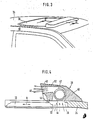
- FIG. 3 shows, as a second exemplary embodiment, a roof part of a motor vehicle with a sliding roof
- FIG. 5 and 6 the third and fourth embodiment each based on one of Figures 2 and 4 corresponding section.
- the motor vehicle according to FIGS. 1 and 2 has a sunroof 10, which covers an opening 12 in the vehicle roof 14 and can be folded from the closed position to the inclined position shown.
- the sun roof 10 itself has an opening 16 (FIG. 2) which extends over a substantial part of the width of the sun roof 10.
- the edge of the opening 16 is encompassed on both sides by a molded-on or otherwise manufactured and fastened housing 18, in which a cross-flow fan 20 is installed.
- This has a radial intake duct 20 on the interior side and an essentially tangential outlet duct 24 above the sunroof plane, which can be closed by a slide 25 or an insertable disc or the like.
- the cross-flow fan 20 there is an electric motor, not visible in the drawing, which is fed by a solar module 26, indicated by a dash-dotted line in FIG. 2, which is attached to the outer skin of the housing 18 and the pane of the sunroof 10.
- the solar module 26 can be mounted on the sun roof 10 in such a way that sufficient solar radiation is ensured in the passenger compartment.
- the translucent pane of the sunroof 10 can advantageously be designed as a fluorescence collector, the edge regions of which are covered by the solar module. Since the fluorescence collector itself is translucent, a sufficient amount of light reaches the passenger compartment through it.
- a switch (not shown) for interrupting the electrical connection between the solar module 26 and the electric motor of the cross-flow fan 20 can expediently be provided on the housing 18.
- the cross-flow fan 20 is driven by the electrical power of the solar module 26 when the sun is shining and the switch is closed.
- air is sucked out of the passenger compartment and transported outside, with outside air entering the passenger compartment through the ventilation ducts of the on-board, battery-powered interior fan. In this way, the temperature in the vehicle is kept within tolerable limits even when the vehicle is parked for a long time and in strong sunlight.
- the motor vehicle has a steel sliding roof 30, which closes an opening 32 in the vehicle roof 34 and is displaceably guided to release the opening in the direction of the double arrow A in FIG. 4.
- the area 36 of the opening 32 facing the windshield of the vehicle is covered by a wind deflector 38, in the housing-shaped base body 40 of which an electrically driven cross-flow fan 42 is integrated.
- This has an intake duct 44 corresponding to the front region 36 of the opening 32 and a blow-out duct 46 lying above the roof plane, which extends through a wing-like extension 48 of the base body 40.
- the gap between the base body 40 and the steel sliding roof 30 is covered by a sealing lip 50 which is fastened to the base body 40 and also prevents the ingress of rain and snow.
- the cross-flow fan 42 has an electric drive motor, not visible in the drawing, which is fed by a solar module 52, indicated by a dash-dotted line in FIG. 4, which covers the outer skin of the wind deflector 38.
- This embodiment has the advantage over that according to FIGS. 1 and 2 that no additional means are necessary to shut off the air path 44, 46 passing through the cross-flow blower 42, because it is completely closed Steel sunroof 30 closes this airway itself tightly.
- an electrical or mechanical locking device for the steel sunroof 30 can also be provided.
- the previous functions of the steel sunroof are also fully retained by the addition of a wind deflector with an integrated ventilation module (fan plus solar module).
- the wind deflector ventilation module can be installed as an accessory without special knowledge by the consumer, whereby no changes need to be made to the vehicle. Wiring with other electrical components of the vehicle is not necessary.
- a sun roof 10 is provided with an opening 16, which extends over a substantial part of the width of the sun roof 10, largely in accordance with the exemplary embodiment according to FIGS. 1 and 2.
- the opening 16 is covered on both sides by a fan housing 58, in which a cross-flow fan 60 is installed. This conveys in the opposite direction to the cross-flow blower 20 according to FIG. 2 and is provided for this purpose with an intake port 62 above the sunroof plane and on the inside with a blow-out opening 64.
- the intake manifold 62 faces the rear of the vehicle and has an intake opening 66 which is delimited at the lower edge by a water-repellent edge 68 projecting above the roof plane.
- the wall section 70 of the fan housing 58 which delimits the upper edge of the suction opening 66 has a shoulder 72 which is inclined obliquely to the roof plane and on which a water tear-off edge 74 is formed.
- a guide plate 76 is provided at the blow-out opening 64 and directs the blown air flow against the steering wheel or the dashboard of the vehicle.
- the device according to FIG. 5 has the advantage that the air conveyed by the cross-flow fan 60 does not flow through any other spaces or ducts in the vehicle body before entering the vehicle interior, where it may. could be heated further.
- the blown-in air is also directed specifically to parts or room areas that heat up particularly strongly when exposed to the sun, so that the device has a good efficiency.
- the exemplary embodiment according to FIG. 6 differs from that according to FIGS. 3 and 4 essentially in that a crossflow fan 80 is arranged in a wind deflector 78 which, like in the exemplary embodiment according to FIG. 5, sucks the outside air directly from the environment and specifically against the dashboard of the Vehicle blows.
- the wind deflector 78 has a housing-shaped base body 82, which forms a short intake port 84 and is provided with a blow-out opening 86 which lies above the opening 32 in the vehicle roof which is covered by the steel sliding roof 30.
- the blow air flow is directed in the desired direction in the blow-out opening 86 and, if appropriate, on the appropriately designed front end edge of the steel sliding roof 30.
- switches 92, 94 On the base body 82 of the wind deflector 78 there are also two switches 92, 94, only shown schematically, which are actuated by the sunroof 30.
- the switches 92, 94 monitor the current supply from the solar module to the fan 80 in such a way that the fan 80 only works in the parked position of the sliding roof 30 corresponding to a defined opening.
- the same switch arrangement could also be provided in the exemplary embodiment according to FIGS. 3 and 4.
Abstract
Description
Die Erfindung geht aus von einer Einrichtung zum Belüften von Räumen in Fahrzeugen nach der Gattung des Hauptanspruchs. Derartige Einrichtungen dienen insbesondere dazu, den Fahrgastraum eines geparkten und der Sonneneinstrahlung ausgesetzten Kraftfahrzeuges zu belüften, um eine zu starke Erwärmung dieses Raumes zu verhindern. Bei einer bekannten Einrichtung der gattungsgemäßigen Art (DE-A1-33 16 823) ist als Tragelement ein kapselförmiges, zweischaliges Gehäuse vorgesehen, welches in eine eigens dafür vorgesehene Öffnung im Karosseriedach des Fahrzeugs eingebaut ist und das Flügelrad des als Axialgebläse ausgebildeten Lüfters mit radialsymmetrischem, verhältnismäßig geringem Spiel umgibt. Diese Ausführung erfordert zusätzliche Teile und Arbeitsgänge zur Bildung des Tragelementes für den Lüfter und den Solarmodul, stört im Fahrgastraum und ist auch insofern nachteilig, weil für die Anbringung des Solarmoduls nur eine verhältnismäßig geringe Fläche an der einen Stirnwand des kapselförmigen Gehäuses zur Verfügung steht. Das hat zur Folge, daß auch nur eine entsprechend geringe Ausgangsleistung des Solarmoduls erzielbar ist, die nicht in jedem Fall eine zufriedenstellende Belüftung gewährleistet.The invention relates to a device for ventilating rooms in vehicles according to the preamble of the main claim. Devices of this type are used, in particular, to ventilate the passenger compartment of a parked motor vehicle which is exposed to solar radiation in order to prevent this space from being excessively heated. In a known device of the generic type (DE-A1-33 16 823), a capsule-shaped, two-shell housing is provided as the supporting element, which is installed in a specially provided opening in the body roof of the vehicle and the impeller of the fan designed as an axial fan with radially symmetrical, relatively little game surrounds. This design requires additional parts and operations to form the support element for the fan and the solar module, disturbs in the passenger compartment and is also disadvantageous in that only a relatively small area is available on one end wall of the capsule-shaped housing for the attachment of the solar module. The result of this is that only a correspondingly low output power of the solar module can be achieved, which does not guarantee satisfactory ventilation in every case.
Ferner ist schon vorgeschlagen worden, zum Belüften des Fahrgastraumes eines geparkten Kraftfahrzeugs an dessen Schiebe- oder Sonnendach einen Solarmodul anzubringen und diesen über Kabel mit einem entfernt angeordneten Lüfter zu verbinden.Furthermore, it has already been proposed to attach a solar module to the passenger compartment of a parked motor vehicle on its sliding or sunroof and to connect it to a remote fan via cables.
Die erfindungsgemäße Anordnung mit dem kennzeichnenden Merkmal des Hauptanspruchs hat demgegenüber den Vorteil, daß zusätzliche Teile zur Bildung des Tragelementes für den Lüfter und den Solarmodul nicht erforderlich sind.The arrangement according to the invention with the characterizing feature of the main claim has the advantage that additional parts for forming the support element for the fan and the solar module are not required.
Durch die in den Unteransprüchen enthaltenen Merkmale sind vorteilhafte Weiterbindungen der Anordnung gemäß dem Hauptanspruch möglich.Due to the features contained in the subclaims, advantageous further bindings of the arrangement according to the main claim are possible.
Besonders vorteilhaft ist es, wenn das Tragelement für den Lüfter und den Solarmodul ein flächenhaftes, zum Öffnen und Schließen einer den zu belüftenden Raum mit dem Freien verbindenden Aussparung in der Fahrzeugkarosserie dienendes Funktionsteil ist. Dadurch ist erreicht, daß für die Anbringung des Solarmoduls eine wesentlich größere Fläche am Tragelement zur Verfügung steht als bei der bekannten Ausführung, so daß ein Solarmodul mit einer den Erfordernissen entsprechenden, auch höheren Ansprüchen genügenden Ausgangsleistung installiert werden kann. Außerdem braucht zusätzliche Öffnung in der Fahrzeugkarosserie und kein zusätzliches Tragelement für die Belüftungseinrichtung vorgesehen werden.It is particularly advantageous if the support element for the fan and the solar module is a planar functional part that serves to open and close a recess in the vehicle body that connects the space to be ventilated with the outside. It is thereby achieved that a much larger area is available on the support element for the attachment of the solar module than in the known embodiment, so that a solar module with an output power that meets the requirements and also meets higher requirements can be installed. In addition, an additional opening in the vehicle body and no additional support element for the ventilation device need to be provided.
Bei einer Einrichtung zum Belüften des Kofferraumes eines geparkten Fahrzeuges bildet erfindungsgemäß der Kofferraumdeckel das Tragelement für den Lüfter und den Solarmodul. Der Kofferraumdeckel kann jedoch auch als Träger für einen den bordeigenen Lüfter des Fahrzeugs speisenden Solarmodul dienen.In a device for ventilating the trunk of a parked vehicle, according to the invention the trunk lid forms the support element for the fan and the solar module. The trunk lid can, however, also serve as a carrier for a solar module which feeds the on-board fan of the vehicle.
Bei einer Einrichtung zur solarbetriebenen Belüftung des Fahrgastraumes eines Kraftfahrzeuges kann als Tragelement für den Lüfter und den Solarmodul vorteilhaft ein Schiebedach oder ein Sonnendach dienen. Besonders zweckmäßig erscheint die Anordnung des Erfindungsgedankens bei für den nachträglichen Einbau auf dem Markt bereits erhältlichen Sonnendächern. Bei einem bereits eingebauten Sonnendach braucht gegebenenfalls nur die Glasscheibe gegen eine erfindungsgemäß mit einem Solarmodul und einem Lüfter kombinierte Scheibe ausgetauscht zu werden.In a device for solar-powered ventilation of the passenger compartment of a motor vehicle, a sunroof or a sunroof can advantageously be used as a supporting element for the fan and the solar module. The arrangement of the inventive concept appears particularly expedient in the case of sunroofs already available on the market for retrofitting. In the case of an already installed sunroof, only the glass pane may need to be exchanged for a pane combined according to the invention with a solar module and a fan.
Bei Verwendung des Sonnendaches als Tragelement für die Belüftungseinrichtung kann die Glasscheibe des Sonnendaches vorteilhaft als Fluoreszenzkollektor ausgebildet sein.When using the sunroof as a supporting element for the ventilation device, the glass pane of the sunroof can advantageously be designed as a fluorescence collector.
Bei einer weiteren bevorzugten Ausführung ist der Lüfter im Inneren eines Windabweisers untergebracht, der ebenfalls als Zubehörteil am Markt erhältlich ist und im Zusammenhang mit einem Schiebedach auch eine natürliche Belüftung des Fahrzeugs während der Fahrt ermöglicht. Für das Solarmodul steht auch in diesem Fall eine genügend große Fläche auf der Außenhaut des Windabweisers zur Verfügung.In a further preferred embodiment, the fan is accommodated inside a wind deflector, which is also available as an accessory on the market and, in conjunction with a sunroof, also enables natural ventilation of the vehicle while driving. In this case, too, there is a sufficiently large area on the outer skin of the wind deflector for the solar module.
Besonders vorteilhaft ist es, wenn die Druckseite bzw. die Ausblasöffnung des Lüfters dem Inneren des zu belüftenden Raumes zugekehrt ist, d.h., wenn Frischluft direkt aus der Umgebung unmittelbar in den zu belüftenden Raum eingeblasen wird. Dadurch wird vermieden, daß die geförderte Luft vor dem Eintritt in den zu belüftenden Raum andere Räume des Fahrzeugs durchströmt, z.B. den Motorraum oder Luftkanäle in der Karosserie, und dort eine zusätzliche Aufheizung erfährt.It is particularly advantageous if the pressure side or the outlet opening of the fan faces the interior of the room to be ventilated, i.e. if fresh air is blown directly into the room to be ventilated from the surroundings. This avoids that the conveyed air flows through other rooms of the vehicle before entering the room to be ventilated, e.g. the engine compartment or air ducts in the body, and there is an additional heating.
In weiterer Ausgestaltung der Erfindung wird vorgeschlagen, der Druckseite des Lüfters mindestens ein Strömungsleitelement zum gezielten Richten des Blasluftstroms in bestimmte Raumbereiche und/oder auf bestimmte Teile, wie Lenkrad, Armaturenbrett, nachzuschalten. Das Strömungsleitelement kann beispielsweise eine verstellbare Frischluftdüse üblicher Bauart oder eine verstellbare Jalousie sein.In a further embodiment of the invention, it is proposed that the pressure side of the fan have at least one flow guide element for targeted Direction of the blown air flow in certain room areas and / or on certain parts, such as steering wheel, dashboard, downstream. The flow guiding element can be, for example, an adjustable fresh air nozzle of a conventional type or an adjustable blind.
In manchen Fällen kann es auch zweckmäßig sein, den Solarmodul bzw. einen weiteren Solarmodul beispielsweise an einem Spoiler des Fahrzeugs anzubringen. Vorteilhaft können auch Mittel zum Verbinden des bzw. der Solarmodule mit externen Geräten vorgesehen sein. Ein gedrängte und für die in Frage kommenden Einbauorte besonders günstige konstruktive Ausführung ergibt sich, wenn der Lüfter ein Tangential- bzw. Querstromgebläse ist.In some cases, it may also be expedient to attach the solar module or a further solar module, for example, to a spoiler of the vehicle. Means for connecting the solar module (s) to external devices can also advantageously be provided. A compact design, which is particularly favorable for the installation locations in question, results if the fan is a tangential or cross-flow fan.
Bei Kraftfahrzeugen, die mit einem elektrischen Zigarettenanzünder versehen sind, kann zur Erhaltungsladung der Fahrzeugbatterie ein Anschlußteil des Solarmoduls als Gegenstecker zum Zigarettenanzünder ausgebildet sein.In motor vehicles which are provided with an electric cigarette lighter, a connection part of the solar module can be designed as a mating connector to the cigarette lighter for maintenance charging of the vehicle battery.
Vier Ausführungsbeispiele der Erfindung sind in der Zeichnung dargestellt und in der nachfolgenden Beschreibung näher erläutert. Es zeigen Figur 1 als erstes Ausführungsbeispiel in perspektivischer Darstellung eine Dachpartie eines Kraftfahrzeuges mit einem ausstellbaren Sonnendach, Figur 2 einen Schnitt nach der Linie II-II in Figur 1, Figur 3 als zweites Ausführungsbeispiel in Perspektive eine Dachpartie eines Kraftfahrzeugs mit einem Schiebedach, Figur 4 einen Schnitt nach der Linie IV-IV in Figur 3, und die Figuren 5 und 6 das dritte und vierte Ausführungsbeispiel je anhand eines der Figuren 2 bzw. 4 entsprechenden Schnittes.Four embodiments of the invention are shown in the drawing and explained in more detail in the following description. 1 shows, as a first exemplary embodiment, a perspective view of a roof part of a motor vehicle with an extendable sunroof, FIG. 2 shows a section along the line II-II in FIG. 1, FIG. 3 shows, as a second exemplary embodiment, a roof part of a motor vehicle with a sliding roof, FIG a section along the line IV-IV in Figure 3, and Figures 5 and 6, the third and fourth embodiment each based on one of Figures 2 and 4 corresponding section.
Das Kraftfahrzeug nach den Figuren 1 und 2 hat ein Sonnendach 10, welches eine Öffnung 12 im Fahrzeugdach 14 überdeckt und aus der Schließstellung bis in die dargestellte Schrägstellung klappbar ist. Das Sonnendach 10 selbst hat eine Öffnung 16 (Figur 2), die sich über einen wesentlichen Teil der Breite des Sonnendaches 10 erstreckt. Der Rand der Öffnung 16 wird beidseitig umgriffen von einem angespritzten oder auf andere Weise hergestellten und befestigten Gehäuse 18, in welches ein Querstromgebläse 20 eingebaut ist. Dieses hat innenraumseitig einen radialen Ansaugkanal 20 und über der Sonnendachebene einen im wesentlichen tangential ausmündenden Ausblaskanal 24, der durch einen Schieber 25 bzw. eine einsetzbare Scheibe oder dergleichen verschließbar ist.The motor vehicle according to FIGS. 1 and 2 has a
An einem Längsende des Querstromgebläses 20 ist ein in der Zeichnung nicht sichtbarer Elektromotor angeordnet, der von einem in Figur 2 durch eine strichpunktierte Linie angedeuteten Solarmodul 26 gespeist ist, welcher auf der Außenhaut des Gehäuses 18 und der Scheibe des Sonnendachs 10 angebracht ist. Auf dem Sonnendach 10 kann der Solarmodul 26 so angebracht sein, daß eine ausreichende Sonneneinstrahlung in den Fahrgastraum gewährleistet ist. Die lichtdurchlässige Scheibe des Sonnendaches 10 kann vorteilhaft als Floureszenzkollektor ausgeführt sein, dessen Randbereiche vom Solarmodul überzogen sind. Da der Fluoreszenzkollektor selbst lichtdurchlässig ist, gelangt durch ihn eine ausreichende Lichtmenge in den Fahrgastraum. Am Gehäuse 18 kann zweckmäßig ein nicht dargestellter Schalter zum Unterbrechen der elektrischen Verbindung zwischen dem Solarmodul 26 und dem Elektromotor des Querstromgebläses 20 vorgesehen sein.At one longitudinal end of the
Ist das Sonnendach geschlossen, so wird bei Sonneneinstrahlung und geschlossenem Schalter das Querstromgebläse 20 durch die elektrische Leistung des Solarmoduls 26 angetrieben. Dadurch wird gemäß den Pfeilen in Figur 2 Luft aus dem Fahrgastraum abgesaugt und ins Freie befördert, wobei Außenluft durch die Belüftungskanäle des bordeigenen, batteriegespeisten Innenraumlüfters in den Fahrgastraum gelangt. Auf diese Weise wird die Temperatur im Fahrzeug auch bei längerer Parkdauer und starker Sonneneinstrahlung in erträglichen Grenzen gehalten.If the sun roof is closed, the
Beim Ausführungsbeispiel nach den Figuren 3 und 4 hat das Kraftfahrzeug ein Stahlschiebedach 30, welches eine Öffnung 32 im Fahrzeugdach 34 verschließt und zum Freigeben der Öffnung in Richtung des Doppelpfeiles A in Figur 4 verschiebbar geführt ist. Der der Frontscheibe des Fahrzeugs zugekehrte Bereich 36 der Öffnung 32 ist überdeckt von einem Windabweiser 38, in dessen gehäuseförmigem Grundkörper 40 ein elektrisch angetriebenes Querstromgebläse 42 integriert ist. Dieses hat einem mit dem vorderen Bereich 36 der Öffnung 32 korrespondierenden Ansaugkanal 44 und einen über der Dachebene liegenden Ausblaskanal 46, der sich durch einen flügelartigen Ansatz 48 des Grundkörpers 40 hindurch erstreckt. Der Spalt zwischen Grundkörper 40 und Stahlschiebedach 30 ist durch eine Dichtlippe 50 abgedeckt, welche am Grundkörper 40 befestigt ist und auch das Eindringen von Regen und Schnee verhindert.In the exemplary embodiment according to FIGS. 3 and 4, the motor vehicle has a
Das Querstromgebläse 42 hat einen in der Zeichnung nicht sichtbaren elektrischen Antriebsmotor, der von einem in Figur 4 durch eine strichpunktierte Linie angedeuteten Solarmodul 52 gespeist ist, welcher die Außenhaut des Windabweisers 38 überdeckt. Diese Ausführung hat gegenüber jener nach den Figuren 1 und 2 den Vorteil, daß zum Absperren des das Querstromgebläse 42 durchsetzenden Luftweges 44, 46 keines zusätzlichen Mittel notwendig sind, weil das völlig geschlossene Stahlschiebedach 30 diesen Luftweg selbst dicht verschließt. In der dargestellen Park-Belüftungsstellung kann auch eine elektrische oder mechanische Arretierung für das Stahlschiebedach 30 vorgesehen sein. Die bisherigen Funktionen des Stahlschiebedaches bleiben auch durch den Anbau eines Windabweisers mit integriertem Lüftungsmodul (Lüfter plus Solarmodul) voll erhalten.The
Die Baueinheit Windabweiser-Lüftungsmodul kann als Zubehörteil ohne Spezialkenntnisse vom Verbraucher installiert werden, wobei keine Veränderungen am Fahrzeug vorgenommen werden müssen. Eine Verkabelung mit anderen elektrischen Bauteilen des Fahrzeugs entfällt.The wind deflector ventilation module can be installed as an accessory without special knowledge by the consumer, whereby no changes need to be made to the vehicle. Wiring with other electrical components of the vehicle is not necessary.
Beim Ausführungsbeispiel nach Figur 5 ist in weitgehender Übereinstimmung mit dem Ausführungsbeispiel nach den Figuren 1 und 2 ein Sonnendach 10 mit einer Öffnung 16 versehen, die sich über einen wesentlichen Teil der Breite des Sonnendaches 10 erstreckt. Die Öffnung 16 wird beidseitig von einem Lüftergehäuse 58 überdeckt, in welches ein Querstromgebläse 60 eingebaut ist. Dieses fördert in entgegengesetzter Richtung wie das Querstromgebläse 20 nach Figur 2 und ist zu diesem Zweck mit einem über der Sonnendachebene liegenden Ansaugstutzen 62 und innenraumseitig mit einer Ausblasöffnung 64 versehen.In the exemplary embodiment according to FIG. 5, a
Der Ansaugstutzen 62 ist dem Fahrzeugheck zugekehrt und hat eine Ansaugöffnung 66, die am unteren Rand von einer über die Dachebene vorstehenden Wasserabweiskante 68 begrenzt ist. Der den oberen Rand der Ansaugöffnung 66 begrenzende Wandabschnitt 70 des Lüftergehäuses 58 hat einen schräg zur Dachebene geneigten Ansatz 72, an der eine Wasserabreißkante 74 gebildet ist. An der Ausblasöffnung 64 ist ein Leitblech 76 vorgesehen, welches den Blasluftstrom gegen das Lenkrad bzw. das Armaturenbrett des Fahrzeugs richtet.The
Die Einrichtung nach Figur 5 hat den Vorteil, daß die vom Querstromgebläse 60 geförderte Luft vor dem Eintritt in das Fahrzeuginnere keine anderen Räume oder Kanäle in der Fahrzeugkarosserie durchströmt, wo sie u.U. weiter aufgeheizt werden könnte. Die eingeblasene Luft wird außerdem gezielt auf Teile bzw. Raumbereiche gelenkt, die sich bei Sonneneinstrahlung besonders stark erwärmen, so daß sich ein guter Wirkungsgrad der Einrichtung ergibt.The device according to FIG. 5 has the advantage that the air conveyed by the
Das Ausführungsbeispiel nach Figur 6 unterscheidet sich von jenem nach den Figuren 3 und 4 im wesentlichen dadurch, daß in einem Windabweiser 78 ein Querstromgebläse 80 angeordnet ist, welches wie beim Ausführungsbeispiel nach Figur 5 die Außenluft direkt aus der Umgebung ansaugt und gezielt gegen das Armaturenbrett des Fahrzeugs bläst. Der Windabweiser 78 hat einen gehäuseförmigen Grundkörper 82, welcher einen kurzen Ansaugstutzen 84 bildet und mit einer Ausblasöffnung 86 versehen ist, die über der vom Stahlschiebedach 30 abgedeckten Öffnung 32 im Fahrzeugdach liegt. In der Ausblasöffnung 86 und gegebenenfalls an dem entsprechend ausgebildeten vorderen Stirnrand des Stahlschiebedaches 30 wird der Blasluftstrom in die gewünschte Richtung gelenkt.The exemplary embodiment according to FIG. 6 differs from that according to FIGS. 3 and 4 essentially in that a
Am Grundkörper 82 des Windabweisers 78 sind ferner zwei nur schematisch dargestellte Schalter 92, 94 vorgesehen, die durch das Schiebedach 30 betätigt werden. Die Schalter 92, 94 überwachen die Stromzufuhr vom Solarmodul zum Lüfter 80 so, daß der Lüfter 80 nur in der dargestellten, einer definierten Öffnung entsprechenden Parkstellung des Schiebedachs 30 arbeitet. Die gleiche Schalteranordnung könnte auch beim Ausführungsbeispiel nach den Figuren 3 und 4 vorgesehen werden.On the
Claims (18)
Applications Claiming Priority (4)
| Application Number | Priority Date | Filing Date | Title |
|---|---|---|---|
| DE3628272 | 1986-08-20 | ||
| DE3628272 | 1986-08-20 | ||
| DE3643436 | 1986-12-19 | ||
| DE3643436A DE3643436C3 (en) | 1986-08-20 | 1986-12-19 | Device for ventilating rooms in vehicles |
Publications (3)
| Publication Number | Publication Date |
|---|---|
| EP0256313A2 true EP0256313A2 (en) | 1988-02-24 |
| EP0256313A3 EP0256313A3 (en) | 1988-11-09 |
| EP0256313B1 EP0256313B1 (en) | 1993-03-24 |
Family
ID=25846712
Family Applications (1)
| Application Number | Title | Priority Date | Filing Date |
|---|---|---|---|
| EP87110210A Expired - Lifetime EP0256313B1 (en) | 1986-08-20 | 1987-07-15 | Device for ventilating vehicle compartments |
Country Status (1)
| Country | Link |
|---|---|
| EP (1) | EP0256313B1 (en) |
Cited By (10)
| Publication number | Priority date | Publication date | Assignee | Title |
|---|---|---|---|---|
| US5003866A (en) * | 1989-03-22 | 1991-04-02 | Ricci Russell L | Car ventilator |
| FR2654679A1 (en) * | 1989-11-17 | 1991-05-24 | Phototronics Solartechnik Gmbh | SOLAR VENTILATION DEVICE FOR THE INTERIOR OF A MOTOR VEHICLE. |
| EP0463351A2 (en) * | 1990-06-29 | 1992-01-02 | Webasto AG Fahrzeugtechnik | Vehicle roof with solar current source and contact device |
| US5156568A (en) * | 1990-03-29 | 1992-10-20 | Ricci Russell L | Car ventilator |
| DE4130226C1 (en) * | 1991-09-11 | 1993-03-11 | Webasto Ag Fahrzeugtechnik, 8035 Stockdorf, De | |
| DE19647730C1 (en) * | 1996-11-19 | 1998-05-20 | Webasto Karosseriesysteme | Folding sunroof for automobile |
| FR2775738A1 (en) * | 1998-03-05 | 1999-09-10 | Schultz Gmbh Aurora | HOOD FAN |
| GB2429518A (en) * | 2005-08-12 | 2007-02-28 | Michael Smith & Associates Ltd | Vehicle roof mounted air extraction unit |
| CN103946044A (en) * | 2011-11-24 | 2014-07-23 | 丰田自动车株式会社 | Vent duct structure for vehicle |
| CN109774424A (en) * | 2019-01-23 | 2019-05-21 | 南昌大学 | A kind of automobile photovoltaic ventilating system |
Families Citing this family (1)
| Publication number | Priority date | Publication date | Assignee | Title |
|---|---|---|---|---|
| US20160047387A1 (en) * | 2014-08-15 | 2016-02-18 | Signature Automotive Products LLC | Systems and methods for air cooling of various enclosures |
Citations (9)
| Publication number | Priority date | Publication date | Assignee | Title |
|---|---|---|---|---|
| US3059562A (en) * | 1957-10-12 | 1962-10-23 | Chrysler Corp | Vehicle window air flow deflector |
| JPS53140731A (en) * | 1977-05-11 | 1978-12-08 | Nippon Soken Inc | Automative ventilator |
| DE2952080A1 (en) * | 1979-12-22 | 1981-06-25 | Daimler-Benz Ag, 7000 Stuttgart | Air conditioning system for automobile - is assigned to passenger and luggage compartment and uses energy obtained from solar cells mounted on roof |
| JPS5867511A (en) * | 1981-10-20 | 1983-04-22 | Nippon Denso Co Ltd | Automobile ventilator |
| FR2543664A1 (en) * | 1983-04-01 | 1984-10-05 | Horreaux Pierre | Method and device for air-conditioning a closed enclosure, such as the passenger compartment of a car |
| DE3329666A1 (en) * | 1983-08-17 | 1985-03-07 | Heiner Dipl.-Ing. 8501 Seligenporten Bauer | Method for operating a car cooling system and car cooling system for carrying out the method |
| US4558634A (en) * | 1983-07-13 | 1985-12-17 | Nippondenso Co., Ltd. | Ventilation system for motor vehicles |
| JPS61132408A (en) * | 1984-11-30 | 1986-06-19 | Fuji Heavy Ind Ltd | Ventilating device for automobile |
| DE3540546A1 (en) * | 1985-11-15 | 1987-05-21 | Farmont Produktion | VENTILATION DEVICE |
-
1987
- 1987-07-15 EP EP87110210A patent/EP0256313B1/en not_active Expired - Lifetime
Patent Citations (9)
| Publication number | Priority date | Publication date | Assignee | Title |
|---|---|---|---|---|
| US3059562A (en) * | 1957-10-12 | 1962-10-23 | Chrysler Corp | Vehicle window air flow deflector |
| JPS53140731A (en) * | 1977-05-11 | 1978-12-08 | Nippon Soken Inc | Automative ventilator |
| DE2952080A1 (en) * | 1979-12-22 | 1981-06-25 | Daimler-Benz Ag, 7000 Stuttgart | Air conditioning system for automobile - is assigned to passenger and luggage compartment and uses energy obtained from solar cells mounted on roof |
| JPS5867511A (en) * | 1981-10-20 | 1983-04-22 | Nippon Denso Co Ltd | Automobile ventilator |
| FR2543664A1 (en) * | 1983-04-01 | 1984-10-05 | Horreaux Pierre | Method and device for air-conditioning a closed enclosure, such as the passenger compartment of a car |
| US4558634A (en) * | 1983-07-13 | 1985-12-17 | Nippondenso Co., Ltd. | Ventilation system for motor vehicles |
| DE3329666A1 (en) * | 1983-08-17 | 1985-03-07 | Heiner Dipl.-Ing. 8501 Seligenporten Bauer | Method for operating a car cooling system and car cooling system for carrying out the method |
| JPS61132408A (en) * | 1984-11-30 | 1986-06-19 | Fuji Heavy Ind Ltd | Ventilating device for automobile |
| DE3540546A1 (en) * | 1985-11-15 | 1987-05-21 | Farmont Produktion | VENTILATION DEVICE |
Non-Patent Citations (4)
| Title |
|---|
| AUTOMOTIVE ENGINEERING, Band 93, Nr. 7, Juli 1985, Seiten 65,66, Warrendale, Pennsylvania, US; D. SCOTT et al.: "Solar energy ventilates experimental car" * |
| PATENT ABSTRACTS OF JAPAN, Band 10, Nr. 326 (M-532)[2382], 6. November 1986; & JP-A-61 132 408 (FUJI HEAVY IND LTD) 19-06-1986 * |
| PATENT ABSTRACTS OF JAPAN, Band 3. Nr. 16 (M-48)[89], 10. Februar 1979, Seite 89 M 48; & JP-A-53 140 731 (NIPPON JIDOSHA BUHIN SOGO KENKYUSHO K.K.) 12-08-1978 * |
| PATENT ABSTRACTS OF JAPAN, Band 7, Nr. 159 (M-228)[1304], 13. Juli 1983; & JP-A-58 67 511 (NIPPON DENSO K.K.) 22-04-1983 * |
Cited By (15)
| Publication number | Priority date | Publication date | Assignee | Title |
|---|---|---|---|---|
| US5003866A (en) * | 1989-03-22 | 1991-04-02 | Ricci Russell L | Car ventilator |
| FR2654679A1 (en) * | 1989-11-17 | 1991-05-24 | Phototronics Solartechnik Gmbh | SOLAR VENTILATION DEVICE FOR THE INTERIOR OF A MOTOR VEHICLE. |
| US5038674A (en) * | 1989-11-17 | 1991-08-13 | Phototronics Solartechnik Gmbh | Solar ventilation arrangement for passenger compartments |
| US5156568A (en) * | 1990-03-29 | 1992-10-20 | Ricci Russell L | Car ventilator |
| EP0463351A2 (en) * | 1990-06-29 | 1992-01-02 | Webasto AG Fahrzeugtechnik | Vehicle roof with solar current source and contact device |
| EP0463351A3 (en) * | 1990-06-29 | 1993-11-24 | Webasto Ag Fahrzeugtechnik | Vehicle roof with solar current source and contact device |
| US5259814A (en) * | 1991-09-11 | 1993-11-09 | Webasto Karosseriesysteme Gmbh | Process for ventilating the interior of a motor vehicle and ventilation system for the performance thereof |
| DE4130226C1 (en) * | 1991-09-11 | 1993-03-11 | Webasto Ag Fahrzeugtechnik, 8035 Stockdorf, De | |
| DE19647730C1 (en) * | 1996-11-19 | 1998-05-20 | Webasto Karosseriesysteme | Folding sunroof for automobile |
| FR2775738A1 (en) * | 1998-03-05 | 1999-09-10 | Schultz Gmbh Aurora | HOOD FAN |
| GB2429518A (en) * | 2005-08-12 | 2007-02-28 | Michael Smith & Associates Ltd | Vehicle roof mounted air extraction unit |
| CN103946044A (en) * | 2011-11-24 | 2014-07-23 | 丰田自动车株式会社 | Vent duct structure for vehicle |
| EP2783886A1 (en) * | 2011-11-24 | 2014-10-01 | Toyota Jidosha Kabushiki Kaisha | Vent duct structure for vehicle |
| EP2783886A4 (en) * | 2011-11-24 | 2015-04-08 | Toyota Motor Co Ltd | Vent duct structure for vehicle |
| CN109774424A (en) * | 2019-01-23 | 2019-05-21 | 南昌大学 | A kind of automobile photovoltaic ventilating system |
Also Published As
| Publication number | Publication date |
|---|---|
| EP0256313A3 (en) | 1988-11-09 |
| EP0256313B1 (en) | 1993-03-24 |
Similar Documents
| Publication | Publication Date | Title |
|---|---|---|
| EP1732775B1 (en) | Motor vehicle roof with solar cells and a device for ventilating and cooling a motor vehicle passenger compartment | |
| DE4022928C1 (en) | ||
| DE3938259C1 (en) | ||
| EP0374421A3 (en) | Wind deflectors for motor vehicle roofs, removable roof segments or the like | |
| EP0428523B1 (en) | Air-conditioning system for motor vehicles | |
| DE3643436C2 (en) | Device for ventilating rooms in vehicles | |
| WO1991018759A1 (en) | Arrangement for cooling the battery of a motor vehicle | |
| EP0256313A2 (en) | Device for ventilating vehicle compartments | |
| EP0151756A2 (en) | Ventilation outlet | |
| EP2303623B1 (en) | Roof module | |
| DE10060610B4 (en) | Vehicle roof with integrated fan | |
| DE2437232C3 (en) | Heating and air conditioning systems for motor vehicles | |
| DE3924755C3 (en) | Device for controlling a vehicle ventilation device | |
| DE10039576A1 (en) | Vehicle heating or air conditioning system has control electronics located in immediate vicinity of air duct casing | |
| DE3316823A1 (en) | Fan for a motor vehicle for ventilating the passenger compartment | |
| DE3610767C2 (en) | ||
| EP2821266A2 (en) | Air conditioning system in the external area of a motor vehicle, in particular bus air conditioning system on a bus roof | |
| EP0187906A2 (en) | Heating device for passenger compartments or the like, particularly in omnibuses | |
| WO2012107164A1 (en) | Roof assembly for a roof of a motor vehicle | |
| DE3624291A1 (en) | Fresh air fan for vehicles | |
| DE3125488C2 (en) | Electric fan | |
| DE3732873C2 (en) | ||
| DE2743226A1 (en) | Wind deflector for lorry - has shoes defining enclosed space with aero-dynamic air inlet openings in bottom coupled to engine air intake | |
| EP0411297A2 (en) | Device for ventilating vehicle compartments | |
| EP0739768B1 (en) | Air conditioner |
Legal Events
| Date | Code | Title | Description |
|---|---|---|---|
| PUAI | Public reference made under article 153(3) epc to a published international application that has entered the european phase |
Free format text: ORIGINAL CODE: 0009012 |
|
| AK | Designated contracting states |
Kind code of ref document: A2 Designated state(s): CH DE ES FR GB IT LI |
|
| PUAL | Search report despatched |
Free format text: ORIGINAL CODE: 0009013 |
|
| AK | Designated contracting states |
Kind code of ref document: A3 Designated state(s): CH DE ES FR GB IT LI |
|
| 17P | Request for examination filed |
Effective date: 19890406 |
|
| 17Q | First examination report despatched |
Effective date: 19900831 |
|
| RAP3 | Party data changed (applicant data changed or rights of an application transferred) |
Owner name: ROBERT BOSCH GMBH |
|
| GRAA | (expected) grant |
Free format text: ORIGINAL CODE: 0009210 |
|
| AK | Designated contracting states |
Kind code of ref document: B1 Designated state(s): CH DE ES FR GB IT LI |
|
| PG25 | Lapsed in a contracting state [announced via postgrant information from national office to epo] |
Ref country code: GB Effective date: 19930324 Ref country code: IT Free format text: LAPSE BECAUSE OF FAILURE TO SUBMIT A TRANSLATION OF THE DESCRIPTION OR TO PAY THE FEE WITHIN THE PRE;WARNING: LAPSES OF ITALIAN PATENTS WITH EFFECTIVE DATE BEFORE 2007 MAY HAVE OCCURRED AT ANY TIME BEFORE 2007. THE CORRECT EFFECTIVE DATE MAY BE DIFFERENT FROM THE ONE RECORDED.SCRIBED TIME-LIMIT Effective date: 19930324 Ref country code: FR Effective date: 19930324 |
|
| REF | Corresponds to: |
Ref document number: 3784981 Country of ref document: DE Date of ref document: 19930429 |
|
| PG25 | Lapsed in a contracting state [announced via postgrant information from national office to epo] |
Ref country code: ES Free format text: LAPSE BECAUSE OF FAILURE TO SUBMIT A TRANSLATION OF THE DESCRIPTION OR TO PAY THE FEE WITHIN THE PRESCRIBED TIME-LIMIT Effective date: 19930705 |
|
| PG25 | Lapsed in a contracting state [announced via postgrant information from national office to epo] |
Ref country code: CH Effective date: 19930731 Ref country code: LI Effective date: 19930731 |
|
| EN | Fr: translation not filed | ||
| GBV | Gb: ep patent (uk) treated as always having been void in accordance with gb section 77(7)/1977 [no translation filed] |
Effective date: 19930324 |
|
| PLBE | No opposition filed within time limit |
Free format text: ORIGINAL CODE: 0009261 |
|
| STAA | Information on the status of an ep patent application or granted ep patent |
Free format text: STATUS: NO OPPOSITION FILED WITHIN TIME LIMIT |
|
| 26N | No opposition filed | ||
| REG | Reference to a national code |
Ref country code: CH Ref legal event code: PL |
|
| PGFP | Annual fee paid to national office [announced via postgrant information from national office to epo] |
Ref country code: DE Payment date: 19970527 Year of fee payment: 11 |
|
| PG25 | Lapsed in a contracting state [announced via postgrant information from national office to epo] |
Ref country code: DE Free format text: LAPSE BECAUSE OF NON-PAYMENT OF DUE FEES Effective date: 19990501 |