EP0256921A1 - Apparatus for automatically personalizing cards - Google Patents
Apparatus for automatically personalizing cards Download PDFInfo
- Publication number
- EP0256921A1 EP0256921A1 EP87401768A EP87401768A EP0256921A1 EP 0256921 A1 EP0256921 A1 EP 0256921A1 EP 87401768 A EP87401768 A EP 87401768A EP 87401768 A EP87401768 A EP 87401768A EP 0256921 A1 EP0256921 A1 EP 0256921A1
- Authority
- EP
- European Patent Office
- Prior art keywords
- card
- personalization
- store
- clamp
- cards
- Prior art date
- Legal status (The legal status is an assumption and is not a legal conclusion. Google has not performed a legal analysis and makes no representation as to the accuracy of the status listed.)
- Granted
Links
Images


Classifications
-
- G—PHYSICS
- G06—COMPUTING; CALCULATING OR COUNTING
- G06K—GRAPHICAL DATA READING; PRESENTATION OF DATA; RECORD CARRIERS; HANDLING RECORD CARRIERS
- G06K19/00—Record carriers for use with machines and with at least a part designed to carry digital markings
- G06K19/06—Record carriers for use with machines and with at least a part designed to carry digital markings characterised by the kind of the digital marking, e.g. shape, nature, code
- G06K19/067—Record carriers with conductive marks, printed circuits or semiconductor circuit elements, e.g. credit or identity cards also with resonating or responding marks without active components
- G06K19/07—Record carriers with conductive marks, printed circuits or semiconductor circuit elements, e.g. credit or identity cards also with resonating or responding marks without active components with integrated circuit chips
- G06K19/077—Constructional details, e.g. mounting of circuits in the carrier
- G06K19/07716—Constructional details, e.g. mounting of circuits in the carrier the record carrier comprising means for customization, e.g. being arranged for personalization in batch
-
- G—PHYSICS
- G06—COMPUTING; CALCULATING OR COUNTING
- G06K—GRAPHICAL DATA READING; PRESENTATION OF DATA; RECORD CARRIERS; HANDLING RECORD CARRIERS
- G06K17/00—Methods or arrangements for effecting co-operative working between equipments covered by two or more of main groups G06K1/00 - G06K15/00, e.g. automatic card files incorporating conveying and reading operations
-
- G—PHYSICS
- G06—COMPUTING; CALCULATING OR COUNTING
- G06K—GRAPHICAL DATA READING; PRESENTATION OF DATA; RECORD CARRIERS; HANDLING RECORD CARRIERS
- G06K19/00—Record carriers for use with machines and with at least a part designed to carry digital markings
- G06K19/06—Record carriers for use with machines and with at least a part designed to carry digital markings characterised by the kind of the digital marking, e.g. shape, nature, code
- G06K19/067—Record carriers with conductive marks, printed circuits or semiconductor circuit elements, e.g. credit or identity cards also with resonating or responding marks without active components
- G06K19/07—Record carriers with conductive marks, printed circuits or semiconductor circuit elements, e.g. credit or identity cards also with resonating or responding marks without active components with integrated circuit chips
- G06K19/077—Constructional details, e.g. mounting of circuits in the carrier
Definitions
- the invention relates to an automatic personalization device for cards and in particular micro-circuit cards such as bank cards.
- bank cards intended for cashless payment, or for example for the automatic withdrawal of banknotes, contain data encoded on the magnetic strips present on these cards. This is generally information concerning the card issuer and the cardholder himself (name, card number, basis for determining the secret code, etc.). Certain information in particular is written in relief on the card (name, number of the holder), so that it can easily appear on the carbon paper stumps after passing the card through an appropriate stump machine. We then speak of cards “embossed”, or better "stamped".
- chips micro-circuits
- the embossed and magnetically coded cards are introduced into magnetic encoder readers which, on the basis of the information provided by the magnetic strip, encode the microcircuits with this same information.
- the SYSCAM Company has marketed such devices under the name of SYSCAM 90.
- This personalization device for memory bank cards uses commercial encoder readers and a microcomputer, of the IBM-PC compatible type which can manage the personalization operations of several readers. Reading the magnetic strip IS02 of the bank card causes the corresponding information to the bearer to be sought on the disks of the SYSCAM microcomputer. These are then encoded on the microcircuit via the chip encoder.
- This device performs the personalization operation relatively slowly (of the order of 30 to 40 seconds), which is moreover consistent with the manual introduction of the cards into the encoder readers. However, it is now desirable to accelerate the rate of manufacture of these cards, at reasonable production costs.
- a second type of manufacturing existing in particular in the United States, consists in using personalization devices which carry out all the personalization operations at the same time, embossing, coding of the magnetic strip, coding of the microcircuit. These devices are however very slow.
- the present invention seeks to overcome the problems resulting from the slowness of the operation of personalizing mixed cards by optimizing the temporal distribution of the tasks necessary for personalization. It thus considerably improves the rate of manufacture of these cards and therefore reduces production costs.
- Another object of the invention is to provide a device for personalizing mixed cards at an affordable price and easy to install.
- the personalization device proposed is of the type comprising at least one card processing device, such as a reader-encoder and an automatic handling machine.
- the processing device comprises several personalization units, each associated with a control unit capable of managing the personalization operations, while the handling automaton comprises: - a specific food store to house the cards to be personalized, - a reception store which can house the correct cards highly personalized, - a waste store capable of housing incorrectly personalized or defective cards, - card gripping means, mounted on a bidirectional movement device for said means, suitable for: . extract a card from the food store, . transfer the card to a personalization unit, . introduce it into said unit, . take it back from said unit, .
- a control logic connected to the control unit to manage the personalization operations, capable of actuating said gripping means and the displacement device so as to interpose, during a personalization operation in a personalization unit, one or more operations for extracting, transferring or unloading a card relating to one or more other personalization units available.
- the automaton further comprises: a card separator device associated with the supply store capable of partially extracting a card from said store, - Card storage devices, respectively associated with the reception store and the waste store, suitable for storing a card in one of said stores.
- the invention is particularly intended for cards comprising one or more coded magnetic tracks and an uncoded micro-circuit, the personalization operation consisting in coding the microcircuit using the data present on the card and / or stored information. in the control unit.
- the personalization units are then mixed magnetic stripe and microcircuit card reader-encoders comprising a memory card connector.
- a variant consists in personalizing the microcircuit from information stamped (or "embossed") on a card, which can be devoid of magnetic strip.
- the personalization units are themselves or include embossing devices or marking devices or even magnetic encoders.
- the food and reception stores are in the form of interchangeable and removable cassettes.
- At least one sensor is associated with the supply magazine in order to detect if the latter is empty, while at least one state switch is associated with the waste magazine in order to detect whether the latter is full.
- the devices for separating or storing cards include at least one preferably reducing motor and a rubber belt preferably coated with a silicone layer.
- the separation device comprises at least one sensor in order to detect if a card has left the supply magazine, the control of the motor of the separation device being maintained as long as said card is not not detected by said sensor.
- Said sensor transmits to the control unit a separation fault signal if the card to be extracted is not detected by the sensor after the time normally provided for the extraction operation, this signal can also be interpreted by the control unit as an empty supply store signal if the control unit simultaneously receives a signal from the sensor associated with the supply store.
- each storage device comprises at least one sensor in order to detect whether a card is present at the entrance to the reception store (respectively scrap), the control of the motor of each storage device being maintained as long as said card is detected by said sensor.
- the card gripping means comprise a clamp preferably controlled by a reduction motor associated with an eccentric.
- said clamp At least two state switches respectively controlling the open and closed positions of the clamp.
- the device comprises: - a preferably DC motor, allowing the displacement of the gripping means along a first axis corresponding to the stop positions of said means in front a store or a personalization unit, - A preferably reducing motor, allowing the movement of the gripping means along a second axis corresponding to the transfer of a card between the gripping means and a personalization unit or a store.
- the movement device is provided with at least one cell allowing the location of a personalization unit or of the selected store along the first axis of movement.
- a movement device comprises at least two safety switches detecting an overtravel along the first axis, respectively provided at the initial position and at the final position of said device on this axis.
- the movement device is provided with at least two safety switches detecting an end of travel along the second axis, respectively provided in the retracted position and in the advanced position of the clamp along this axis.
- the movement device At the same time, it is associated with the movement device at least one switch, placed at the entrance to each store, making it possible to position the clamp in front of the corresponding store.
- the personalization units each comprise a guide assembly capable of allowing the correct introduction of a card into said unit and of compensating for positioning deviations.
- Each personalization unit advantageously comprises a contact indicating the insertion and correct positioning of a card in said unit and transmitting a signal to the control unit of the personalization units initiating the personalization operation.
- the control unit for the personalization units is preferably programmed so that it sends a series of signals to the control unit indicating: - the availability status of the personalization units, - the state of completion of the personalization operation in progress in the personalization units in operation, - the end of personalization operation of the card being processed in the personalization unit, - the result of the personalization operation for said card.
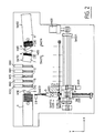
- FIG. 1 and 2 there is shown the personalization apparatus as a whole. This consists of a table capable of supporting the various sub-assemblies of the device.
- the apparatus schematically comprises a supply magazine 1, containing the cards to be personalized, a device for separating the cards 2 (also called “destacker"), gripping means 3, which can be, for example, pliers, a device for bidirectional movement 4, a set of five reader-encoders 5, a scrap store for housing defective cards 7, itself provided with a card storage device 8 (also called “stacker”), and a reception store 6 for accommodating personalized cards, also provided with a card storage device 9.
- a supply magazine 1 containing the cards to be personalized
- a device for separating the cards 2 also called “destacker”
- gripping means 3 which can be, for example, pliers
- a device for bidirectional movement 4 a set of five reader-encoders 5
- a scrap store for housing defective cards 7, itself provided with a card storage device 8 (also called
- the magazines and the reader-encoders are situated substantially on the same axis while the displacement device is arranged on an axis X parallel to the axis of the magazines and the reader-encoders.
- the gripper, perpendicular to the displacement device therefore moves along a Y axis, perpendicular to the X axis, and faces the magazines and the reader-encoders.
- the table T can be covered with a protective cover, not shown.
- the overall dimensions are typically as follows: 1100 x 800 x 300 mm.
- the whole of the automaton is fixed on a plate having good rigidity.
- a card to be personalized, contained in the supply magazine 1 is "unstacked" using the separation device 2, actuated by a motor M10.
- the clamp 3 controlled by the motor M20, then grabs the card and transfers it by making a bidirectional movement towards the reader-encoders 5, where it deposits it.
- This clamp 3 is moved along the two horizontal axes perpendicular to each other, X and Y, by the displacement device 4.
- the displacement device is actuated by two motors M21, M22.
- the clamp 3 picks up the personalized (or possibly defective) card and discharges it in one of the appropriate outlet stores, the reception store 6 or the waste store 7 for defective cards.
- "Stackers" 8 and 9 (actuated by motors M30 and M40 respectively) ensure the introduction of the card.
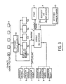
- FIG. 3 more particularly illustrates how the different assemblies of the personalization device according to the invention are electrically connected to each other.
- a control logic L centralizes the management of the various operations of the PLC. It first receives the input from stores 1, 6, 7 (store status) as well as the separating devices associated with each store 2, 9, 8. This information is given by sensors or switches indicated on Figure 2 respectively by the letters C and SW.
- Photoelectronic couplers are provided on the input lines to ensure galvanic isolation.
- the control unit also receives the data coming from the reader-encoder control unit U.
- This unit manages the personalization operations specific to reader encoders 5-1, ... 5-5.
- Contacts R make the mechanical interface between the PLC and this control unit U.
- the control logic L is in the preferred embodiment of the invention a microprocessor of the INTEL family of the 8088 type. It manages only the operations relating to the animation of the automaton. As for the reader control unit, it is typically an IBM-PC microcomputer (or any compatible with the latter).
- the RS 232C link can also be used for a possible download of the PLC software.
- the control logic L is provided, either with read only, programmable and erasable REPROM memory in the case where the management program of the automaton is frozen, or with a random access memory RAM in the case of a download. It turned out that a capacity of 8 kilobytes was sufficient.
- the control logic L also comprises output lines for transmitting interrupt or control signals to the actuator motors M, and possibly a light or sound display device for alarm messages. This is in particular the case of the motor M20 (opening and closing of the clamp 3), of the motors 21 and M22 (displacement device 4 along the axes X or Y). Relays (case of the commands for the motors M21 to M22 ) or power transistors (other cases) serve as interfaces on these output lines.
- the input and output cards can be modular and separate.
- FIG. 4 describes in detail the supply magazine 1 of FIGS. 1 and 2, as well as the separation device 2 ("destacker").
- the food store is in the form of a removable cassette which can contain, for example, up to 200 cards.
- the cards previously embossed, have standard dimensions: 86 x 54 mm (ISO 3554 standard).
- ISO 3554 standard ISO 3554 standard.
- mixed cards comprising both a magnetic strip, of the IS02 type, and a microcircuit. Stacked, one against the other, they are all oriented in the same way, the microcircuit being on the external side with respect to the displacement device.
- the cassette where approximately 200 cards can be placed vertically, therefore has typical dimensions: 90 x 90 x 300 mm.
- a plate 1.1 provided with springs 1.2 and 1.3 exerts pressure on the stack of cards 1.5 and keeps them vertical.
- This vertical arrangement was considered preferable to a horizontal arrangement; in the latter, in fact, the embossed cards, laid flat, would slide to the side of thinner thickness.
- the uniform pressure exerted by the plate 1.1 on the vertical cards overcomes this drawback.
- a cell C10 of the reflection sensor type, makes it possible to indicate whether the magazine is empty.
- an OPB 703A cell is used.
- the separation device 2 of Figures 1 and 2. It comprises two pulleys 2.1 and 2.2 and a reduction motor M10 provided with a rotation shaft.
- a rubber belt 2.4 coated with a silicone layer is stretched over the two pulleys 2.1 and 2.2 and a roller 2.3 mounted on the rotation shaft.
- the separation device or "destacker" 2 is placed at the end of the supply magazine 1, facing the latter.
- the pulleys 2.1 and 2.2 are positioned so that the belt 2.4 is placed against the card to be removed from magazine 1.
- a cell C11 of the same type as C10 is located in the extension of the width of the magazine, in the direction of extraction of the card. This cell C11 controls the reduction motor M10. As long as the card to be extracted does not hide this cell C10, the engine actuation command M10 is maintained. Cell C10 is placed so that the card comes out about 50 mm from tray 1.
- the engine actuation command M10 is stopped. This is triggered again when the clamp 3 grasps the extracted card.
- the freewheel mounted on the motor axis of M10 allows an easy grip of the card by the clamp.
- the M10 engine is then started again, which causes the rotation of the belt 2.4 and the extraction of a new card.
- the extraction operation takes approximately 2.5 seconds.
- the control logic L which manages all the operations of the automaton is programmed so that if after a determined time, for example 3 seconds, the cell C11 has not sent a signal indicating the detection of a card one light (or sound) alarm is activated.
- the control logic L then examines whether it has already recorded a signal from the cell C10 detecting an empty supply magazine. Two alarm signals are therefore to be considered: the first (light or sound, or possibly display on a video terminal) indicates an anomaly in the separation device 2; the second, different from the first (for example light and sound, or possibly display on a video terminal), signals an empty food store.
- the absence of cards obviously results in cell C11 being unable to detect any card, without the destacker itself having a malfunction.
- FIG. 5a represents the gripping means 3.
- the latter are presented in an embodiment of the invention in the form of a clamp 3, with flat and mobile ends and capable of appropriately gripping an embossed card.
- the cards are stacked in the feed magazine so that the microcircuit, generally located in an upper corner of the card, is located on the side outside the movement device assembly. - pliers.
- the clamp 3 grasps the card so that the card is firmly held.
- Sufficient space must be provided for the clamp to be able to move above the reader-encoders.
- the clamp 3 is controlled by an M20 gearmotor.
- a motor is associated with an eccentric, which allows greater precision in the movement.
- This motor transmits, via a cam 3.1, movements at the flat ends of the clamp and uses only one direction of rotation.
- the arms of the clamp are biased on the eccentric by a spring 3.2.
- SW200 and SW201 microswitches arranged inside the clamp actuate the opening and closing of the clamp and make it possible to send the signals clamp open, clamp closed to the control unit at any time. These switches are miniaturized and come in the form of microswitches. Typically, these are QS microswitches, of the AH 3206 type.
- the M20 motor is directly controlled by the control logic L.
- the clamp 3 has two degrees of freedom.
- the first, along the Y axis, corresponds to the advancement (respectively withdrawal) of the clamp towards a store or a reader (respectively of a store or a reader). It is allowed thanks to a spring 3.3 arranged on the axis on which the clamp is mounted.
- the other, along the X axis, allows the clamp to absorb positioning errors at the level of the readers. It is made possible by the action of two flexible washers, not shown.
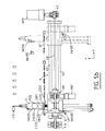
- FIG. 5b illustrates the displacement device as well as the clamp previously described.
- the first corresponds to the stop positions of the trolley in front of one of the stations of the personalization device, namely a store (supply 1, scrap 7, reception 6) or a reader-encoder 5
- the clamp 3 then remains fixed along the Y axis, while the carriage 4.1 moves along the X axis.
- the second corresponds to the advancement (respectively to the withdrawal) of the clamp 3 towards a magazine (1, 6, 7) or a reader-encoder 5 (respectively store or reader-encoder).
- the carriage 1 then remains fixed, while the clamp 3 is movable along the Y axis.
- the displacements along the X axis are controlled by an M22 motor, preferably a DC motor.
- the device comprises two guide tubes 4.2 and 4.3 on which the carriage 4.1 is housed.
- a belt 4.4 is stretched between a roller 4.5 mounted on the axis of the M22 engine and a return roller 4.6.
- the carriage 4.1 is also fixed to this belt 4.4 and moves under the action of the rotation of the belt 4.4, itself moved by the rotational movement of the motor shaft M22.
- Two switches SW220 and SW221 are provided at the two ends, on either side of the carriage stroke to interrupt the control of the motor M22 in the event of overtravel. These are QS roller lever microswitches of type AN 3266.
- the carriage stroke is limited on one side by the position of the carriage 4.1 in front of the feed magazine 1 (initial position), and on the other by the position in front of an outlet store, for example in the embodiment described, the store receiving 6 personalized cards.
- a slide bar 4.7 comprising a number of holes corresponding to the different positions of the three magazines (1, 6, 7) and the five reader-encoders 5. These holes are detected by an optical cell at C221 transmission located at the base of the clamp, on the side of the carriage. The latter therefore "sees” the different holes located on the strip 4.7 and sends a signal to the control unit at each hole detected, when this cell C221 is no longer obscured.
- the umpteenth signal corresponding to the umpteenth hole detected is interpreted as a stop signal by the communication logic command which then stops the M22 engine.
- the carriage is thus positioned in front of the desired station.
- the carriage does not stop instantaneously and the precision obtained in the stop position can then be poor.
- the interpretation of the signals and the stopping of the engine are carried out almost instantaneously.
- the M22 motor shaft also has a moment of inertia, as does the belt, which also contributes to incorrect positioning of the carriage.
- two other cells C220 and C222 are placed on either side of cell C221. These also detect the holes in the strip and at the umpteenth hole sought, trigger a signal interpreted by the control unit, as a slowdown signal.
- the cell C220 intervenes in the case of a displacement in the direction of the initial position (supply magazine 1), while the cell C222 intervenes in the case of a displacement of direction coming from the initial position.
- Cell C221 then transmits a complete stop signal.
- the positioning accuracy obtained is much better and of the order of ⁇ 0.5 mm.
- the displacements along the Y axis are controlled by an M21 motor, preferably a geared motor.
- the motor shaft M21 is connected by a belt to a deflection roller 4.8, which using a belt 4.9 and a worm, generates a linear movement of the clamp 3.
- the linear movement speed of the clamp 3 along the Y axis must be chosen between 50 and 100 mm / sec. to allow the magnetic reader 5 to be able to correctly read the data encoded on the magnetic strip. Reading such data requires the scrolling of this track above a playhead.
- this speed was chosen to be of the order of 60 mm / sec.
- two lever switches with limit switches SW 210 and SW 211 are provided at the two ends of the gripper stroke in order to interrupt the control of the motor M21 by overtravel. They correspond respectively to the recessed position of the clamp 3 and to the advanced position of the clamp. A positioning accuracy of the order of a millimeter is thus obtained.
- FIG. 5a there is shown the position of the recessed clamp.
- the safety device SW 210 makes it possible to interrupt the control of the motor in the event of overtravel in the retracted position.
- Another sensor C 210 located projecting from the carriage and mounted thereon, is provided to instruct the control logic in the position "withdrawal of the clamp". This cell C 210 is obscured by a flag mounted on the clamp when the latter is positioned back. The control unit is then informed of the step carried out and can execute the next. This step will therefore generally be a movement along the X axis to find a specific position.
- FIGs 6, 7, 8 illustrate different modes of operation of the clamp.
- the clamp 3 is shown in the advanced position in front of the supply magazine 1.
- the clamp is ready to extract a card.
- a switch SW 212 is placed at the entrance of each store to interrupt the control of the motor M21.
- the stores are in fact placed slightly ahead of the reader-encoders on the one hand; the cards are also taken into account by the separation (or storage) devices, which does not require such advancement of the clamp.
- the switch SW 212 therefore performs this task.
- FIG 7 the clamp is shown in the advanced position in front of the magazine for receiving 6 valid cards.
- a switch SW 214 of the microswitch type with a lever with a roller interrupts the control of the motor M21 for advancing the gripper so that the gripper is correctly positioned in front of the storage device 9.
- the outlet stores are also shown in this figure. These are the waste magazine 7 for defective cards and the reception magazine 6 for personalized cards, as well as their associated storage devices 9 and 8.
- the receiving magazine 6 is in fact identical to the food magazine 1, previously described in FIG. 4. It is therefore again a removable cassette, of standard size 90 X 90 X 300mm, which can contain approximately 200 cards. embossed.
- a storage device 9 identical to the separation device in FIG. 4. Instead of extracting the cards, this device stacks them vertically in the receiving magazine 6.
- a sensor C40 controls the motor M40 of the storage device 9 as long as the card is present in front of the sensor C40. Unlike the sensor C11 in FIG. 4, the sensor C40 is placed on the outer edge of the reception magazine 6, so that, when the sensor C40 no longer "sees” the card, it is already correctly stacked in the magazine 6. A short latency period can be provided so that the M40 engine does not stop until the card to be stacked is correctly inserted in the receiving magazine 6.
- the waste magazine 7 capable of containing defective cards is identical in nature to the two other magazines 1 and 6 already described, but has reduced dimensions, typically 75 X 90 X 90 mm because it is not likely to contain a large number cards, on average at most 30 cards.
- the scrap store 7 is also provided with a switch SW30 placed at the bottom of the store 7 indicating a state of full waste store. It is associated with a storage device 8 identical to those previously described.
- the M30 motor is located on the internal side of the controller.
- a C30 sensor controls this M30 engine.
- the magazines 6 and 7 are slightly inclined in opposite directions on the magazine-reader-encoder axis. Such an inclination indeed promotes better gripping of the card by the storage devices 8, 9 as well as easier introduction into the stores 6, 7.
- the clamp 3 is in the advanced position in front of one of the reader-encoders.
- the clamp moves ering at a uniform speed moved to the end of its travel by inserting the bank card C into the reader-encoder 5.3.
- the latter can thus read the data encoded on the magnetic strip.
- the control logic L is informed of the advanced position of the clamp 3 in front of one of the reader-encoders and so that it then controls the interruption of the motor M21 when the clamp 3 reaches the desired position, it is provided a C211 sensor, placed below the clamp 3.
- the cell C211 of the transmission sensor type, is obscured by a flag 53, placed opposite the corresponding reader-encoder.
- the overtravel switch SW211 already mentioned, stops the motor M21 in the event of a malfunction of the cell C211.
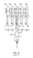
- the reader-encoders 5.1 to 5.5 are shown.
- bank cards are indeed mixed cards, comprising both a magnetic stripe and a micro-circuit.
- the reader-encoders must therefore be able to read the information coming from the magnetic strip, to transmit it to the disks of the control unit U where all the other dependent information is stored and to encode it on the micro-circuit.
- reader-encoders Given current practical and economic data, the number of reader-encoders has been limited to five. These reader-encoders are stored one after the other, at an interval of 45 mm.
- the mixed reader-encoder 5 therefore comprises, on the one hand, a commercial manual reader for reading the track IS02. On the other hand, and on the rear, in the extension of this is placed a memory card connector of the Bull CP8 type, for example.
- the card captured by the clamp is therefore first inserted into the magnetic reader at the speed of 60 mm / s.
- the card reaches the back of the mixed reader, it has been read by the magnetic reader and it is in the correct position for the personalization operation. It is then released by the clamp which is withdrawn.
- the correct position of the card in a mixed reader-encoder is indicated by a contact (R50, R60, ..., R90) located at the rear of the mixed reader-encoder. It is this signal which on the one hand causes the release of the clamp 3 and the withdrawal of the clamp 3, on the other hand triggers the personalization operation.
- the latter are fitted at their entry with a flared lip guide device (for example 56 for 5.1). Any other device capable of properly driving the cards inside the mixed reader-encoders can be used.
- Card C is routed to the bottom of the reader-encoder by clamp 3 itself. It is also possible to provide small transport rollers which would introduce the card and extract it by allowing the clamp 3 to remain positioned opposite the reader-encoder.
- the control unit U which manages the personalization operations is in one embodiment, a microcomputer, of the IBM-PC compatible type, with 256 kilobytes of RAM and comprising two 5 "1/4 floppy drives. sends a signal indicating a personalization operation to the control logic L of the PLC, as long as this operation is in progress. At the end of this operation, the microcomputer then sends an end signal to the control logic L which memorizes it.
- the end signals are noted MCR50, ..., 90.
- FIG. 9 schematically illustrates how the various assemblies of the apparatus are connected to the control logic of the automaton, which manages all of its operations as well as its relations with the control of the reader-encoders U.
- the inputs are the signals sent by the various sensors and switches as well as the signals emitted by the control of the reader-encoders U.
- the sensor C10 sends an empty magazine signal to the logic L. In conjunction with the sensor C11, it allows the display of the signal "empty magazine supply” and causes the engine M10 to stop.
- These sensors C11, C30 and C40 govern the extraction or the loading of a card. They respectively have an action on the M10, M30 and M40 motors and can trigger a "separation fault” or “storage fault” signal. They also operate the M20 motor (opening or closing of clamp 3).
- the switch SW30 allows the display of the "waste magazine full” signal and can cause one or more motors, or even all, to stop (stop of the automaton for fear of damaging the cards).
- the switch SW60 it indicates that a replacement of reception cassette is in progress, which, in a preferred embodiment, causes the stopping of all the motors.
- C220, C221 and C222 sensors are used to position the carriage 4.1 and have an action on the M22 engine.
- the C211 and C210 sensors instruct the logic L on the position of the clamp 3 on the Y axis, which allows it to perform the next step. (actuation of the motor M20 in the case of the sensor C211, actuation of the motor M22 in the case of the sensor C210).
- the switches SW200 and SW201 are switches actuating the opening and closing of the clamp 3 (action on the motor M20). As for the switches SW 210 and SW 211, SW220 and SW221, they have an action respectively on the motors M21 or M22 in the event of movement overtravel. Finally the contacts R50, ..., R90 (reed relay contacts) have an action on the command of reader-encoders U, since they initialize the personalization operation.
- the microcomputer U which controls the reader-encoders 5 sends a signal "operation in progress" or "end of operation" to the control logic L which stores it.
- This table presents four columns indicating for each operational position (that is to say each sub-assembly relating to an operation), the motor actuated and the sensors or switches controlling this motor. The last column then translates the action concerned in terms of functions.
- the motor M10 is controlled by the sensors C10 and C11, C10 indicating an empty supply magazine while C11, if it is triggered, sends no signal to M20 so that the clamp opens.
- the switches SW201 and SW200 determine the state of the clamp (clamp open or closed).
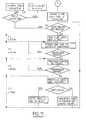
- FIG. 11 illustrates a sequential diagram of the personalization operations relating to a card.
- the card to be personalized must first be advanced by the destacker. Two cases then arise: - The card is not present, which implies either that the feed store 1 is empty, or that the card separation system 2 has an anomaly. In both cases, an alarm signal is issued; - the card is present under the destacker 2.
- the card is taken up by the clamp 3 and transferred, depending on whether it is defective or not, to one of the outlet stores 6 or 7.
- This operation lasts approximately 3 s.
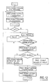
- FIG. 12 shows the diagram for managing the personalization operations for all of the reader-encoders.
- the diagram accepts as hypotheses: - that in the established regime, a card unloading is followed as soon as a new card is loaded; - that, if the personalization operation for a reader-encoder has not been completed, the following reader-encoder is immediately taken into account; - that the personalization operations on the various reader-encoders are carried out sequentially (reader-encoder 5.1 to 5.5, then again reader-encoder 5.1); - that the cards in the receiving store 6 of the valid cards must be arranged in the same order as that in the food store 1.
- the clamp can then be programmed to wait a few seconds so that 30 s. have elapsed, corresponding to the personalization time of the 5.1 reader-encoder card.
- the control logic L then examines whether the personalization operation is finished. In this case, it examines whether the card is valid. These two completed-validity personalization information are sent jointly by the command of the readers U to the control logic L at the end of each personalization operation. Depending on the validity of the card, the clip which has moved to the 5.1 reader-encoder, unloads the card in one of the designated stores.
- the clamp In the event that a personalization operation is not completed, the clamp, programmed by the control logic L, marks a pause time and waits for the operation of the reader-encoder in play to be completed.
- the controller thus proceeds to the fifth reader-encoder and starts the cycle again from the first reader-encoder.
- the present invention is not limited to the embodiments described. Although it is advantageous to use only four or five reader-encoders, it is of course possible to use a greater number of reader-encoders depending on the solution of the current technique.
- the personalization of the cards can be done following an optical reading of the characters stamped on the card, for example using an OCR reader.
- OCR reader can be placed at the level of each personalization unit, or else a single reader is pooled at the outlet of the food store.
- the data to be personalized can be acquired by any other device for reading the data present on the card, for example by laser reading of inscriptions with microperforations.
- the present invention is also not limited to the means provided for storing, separating, storing or transporting the cards. These can, in fact, be designed differently, while keeping the functions described above.
- the basic information is received by downloading and all the card personalization operations are carried out in the device, namely embossing, magnetic encoding and loading of the micro-circuit.
- some cards carry the micro-circuit not in a corner, but near the middle of one of the widths of the card. It will of course be possible to adapt the reader-encoders as well as the position for gripping a card with the clamp.
- Downloading the program from the PLC is also conceivable, without this modifying the scope of the invention described above.
Abstract
L'invention concerne un appareil de personnalisation de cartes comprenant au moins un dispositif de traitement desdites cartes et un automate de manipulation. Le dispositif de traitement comprend plusieurs unités de personnalisation (5) associées à une unité de commande. L'automate de manipulation comprend un magasin d'alimentation (1), un magasin de réception (6), un magasin de rebut (7) et des moyens de préhension de cartes (3) montés sur un dispositif de déplacement bidirectionnel (4), une logique de commande (L) étant reliée à l'unité de commande pour gérer les opérations de personnalisation.The invention relates to a card personalization apparatus comprising at least one device for processing said cards and an automatic handling machine. The processing device comprises several personalization units (5) associated with a control unit. The handling machine comprises a feed magazine (1), a reception magazine (6), a scrap magazine (7) and card gripping means (3) mounted on a bidirectional movement device (4) , a control logic (L) being connected to the control unit to manage the personalization operations.
Description
L'invention concerne un appareil de personnalisation automatique de cartes et en particulier de cartes à micro-circuit telles que les cartes bancaires.The invention relates to an automatic personalization device for cards and in particular micro-circuit cards such as bank cards.
Les progrès de la monétique ont favorisé le développement de cartes bancaires émises par des banques, des sociétés de crédit ou autres établissements financiers analogues.Advances in electronic banking have favored the development of bank cards issued by banks, credit companies or other similar financial institutions.
Ces cartes bancaires, destinées au paiement sans espèces, ou par exemple au retrait automatique de billets de banque, contiennent des données codées sur les pistes magnétiques présentes sur ces cartes. Il s'agit en général d'informations concernant l'émetteur de la carte et le titulaire lui-même (nom, numéro de la carte, base de détermination du code secret, ...). Certains renseignements en particulier sont inscrits en relief sur la carte (nom, numéro du porteur), afin qu'ils puissent apparaître aisément sur les souches de papier carboné après passage de la carte dans un appareil à souches approprié. On parle alors de cartes "embossées", ou mieux "estampées".These bank cards, intended for cashless payment, or for example for the automatic withdrawal of banknotes, contain data encoded on the magnetic strips present on these cards. This is generally information concerning the card issuer and the cardholder himself (name, card number, basis for determining the secret code, etc.). Certain information in particular is written in relief on the card (name, number of the holder), so that it can easily appear on the carbon paper stumps after passing the card through an appropriate stump machine. We then speak of cards "embossed", or better "stamped".
Plus récemment, on a pu observer l'introduction de micro-circuits ("puces") sur ces cartes à piste magnétique. Ces dernières se présentent donc sous la forme de cartes mixtes, présentant à la fois une mémoire électronique et au moins une piste magnétique (piste IS02).More recently, we have observed the introduction of micro-circuits ("chips") on these magnetic stripe cards. These are therefore in the form of mixed cards, having both an electronic memory and at least a magnetic strip (track IS02).
Ces deux supports, microprocesseur et piste magnétique, doivent donc recevoir les mêmes informations, l'introduction du support électronique s'expliquant pour des raisons de sécurité d'emploi (inviolabilité).These two supports, microprocessor and magnetic strip, must therefore receive the same information, the introduction of the electronic support being explained for reasons of job security (inviolability).
Néanmoins, si la personnalisation de la carte par sa piste magnétique est très rapide (inférieur à 1 second), celle relative au microcircuit prend au moins plusieurs dizaines de secondes (30 à 40 secondes).However, if the personalization of the card by its magnetic strip is very fast (less than 1 second), that relating to the microcircuit takes at least several tens of seconds (30 to 40 seconds).
On connaît deux types de fabrication de telles cartes mixtes. Dans le premier cas, les cartes embossées et magnétiquement codées, sont introduites dans des lecteurs magnétiques encodeurs qui, à partir des informations fournies par la piste magnétique, encodent les microcircuits avec ces mêmes informations. La Société SYSCAM a commercialisé de tels appareils sous le nom de SYSCAM 90. Cet appareil de personnalisation de cartes bancaires à mémoire utilise des lecteurs encodeurs du commerce et un micro-ordinateur, du type compatible IBM-PC qui peut gérer les opérations de personnalisation de plusieurs lecteurs. La lecture de la piste magnétique IS02 de la carte bancaire provoque la recherche des informations correspondantes au porteur sur les disques du microordinateur SYSCAM. Ces dernières sont alors encodées sur le microcircuit par l'intermédiaire de l'encodeur à puce.Two types of manufacture of such mixed cards are known. In the first case, the embossed and magnetically coded cards are introduced into magnetic encoder readers which, on the basis of the information provided by the magnetic strip, encode the microcircuits with this same information. The SYSCAM Company has marketed such devices under the name of SYSCAM 90. This personalization device for memory bank cards uses commercial encoder readers and a microcomputer, of the IBM-PC compatible type which can manage the personalization operations of several readers. Reading the magnetic strip IS02 of the bank card causes the corresponding information to the bearer to be sought on the disks of the SYSCAM microcomputer. These are then encoded on the microcircuit via the chip encoder.
Cet appareil effectue assez lentement l'opération de personnalisation (de l'ordre de 30 à 40 secondes), ce qui est d'ailleurs cohérent avec l'introduction manuelle des cartes dans les lecteurs encodeurs. Mais il est maintenant souhaitable d'accélérer la cadence de fabrication de ces cartes, à des coûts de production raisonnables.This device performs the personalization operation relatively slowly (of the order of 30 to 40 seconds), which is moreover consistent with the manual introduction of the cards into the encoder readers. However, it is now desirable to accelerate the rate of manufacture of these cards, at reasonable production costs.
Il serait envisageable d'associer à chacun de ces lecteurs encodeurs un automate de manipulation qui alimenterait ceux- ci de cartes à personnaliser à la fin de chaque opération de personnalisation. Cette disposition ne serait cependant pas économiquement satisfaisante et ne résoudrait de toute façon pas les problèmes de lenteur liés à l'opération de personnalisation.It would be possible to associate with each of these encoder readers a handling automaton which would supply them ci of cards to personalize at the end of each personalization operation. This arrangement would however not be economically satisfactory and would not in any case solve the problems of slowness linked to the personalization operation.
Un deuxième type de fabrication, existant en particulier aux Etats-Unis, consiste à utiliser des appareils de personnalisation qui réalisent toutes les opérations de personnalisation à la fois, embossage, codage de la piste magnétique, codage du microcircuit. Ces appareils sont cependant très lents.A second type of manufacturing, existing in particular in the United States, consists in using personalization devices which carry out all the personalization operations at the same time, embossing, coding of the magnetic strip, coding of the microcircuit. These devices are however very slow.
La présente invention cherche à pallier les problèmes résultant de la lenteur de l'opération de personnalisation de cartes mixtes en optimisant la répartition temporelle des tâches nécessaires à la personnalisation. Elle permet d'améliorer ainsi considérablement la cadence de fabrication de ces cartes et donc d'en alléger les coûts de production.The present invention seeks to overcome the problems resulting from the slowness of the operation of personalizing mixed cards by optimizing the temporal distribution of the tasks necessary for personalization. It thus considerably improves the rate of manufacture of these cards and therefore reduces production costs.
Un autre but de l'invention est de fournir un appareil de personnalisation de cartes mixtes à un prix accessible et d'installation facile.Another object of the invention is to provide a device for personalizing mixed cards at an affordable price and easy to install.
L'appareil de personnalisation proposé est du type comprenant au moins un dispositif de traitement de cartes, tel qu'un lecteur-encodeur et un automate de manipulation. Dans sa définition la plus générale, le dispositif de traitement comprend plusieurs unités de personnalisation, associées chacune à une unité de commande propre à gérer les opérations de personnalisation, tandis que l'automate de manipulation comprend :
- un magasin d'alimentation propre à loger les cartes à personnaliser,
- un magasin de réception propre à loger les cartes correc tement personnalisées,
- un magasin de rebut propre à loger les cartes incorrectement personnalisées ou défectueuses,
- des moyens de préhension des cartes, montés sur un dispositif de déplacement bidirectionnel desdits moyens, propres à :
. extraire une carte du magasin d'alimentation,
. transférer la carte au niveau d'une unité de personnalisation,
. l'introduire dans ladite unité,
. la reprendre de ladite unité,
. la transférer au niveau du magasin de réception, ou du magasin de rebut si elle est défectueuse,
. la décharger dans le magasin de réception, ou dans le magasin de rebut si elle est défectueuse,
- une logique de commande, reliée à l'unité de commande pour gérer les opérations de personnalisation, aptes à actionner lesdits moyens de préhension et le dispositif de déplacement de manière à intercaler pendant une opération de personnalisation dans une unité de personnalisation, une ou plusieurs opérations d'extraction, de transfert ou de déchargement d'une carte relatives à une ou plusieurs autres unités de personnalisation disponibles.The personalization device proposed is of the type comprising at least one card processing device, such as a reader-encoder and an automatic handling machine. In its most general definition, the processing device comprises several personalization units, each associated with a control unit capable of managing the personalization operations, while the handling automaton comprises:
- a specific food store to house the cards to be personalized,
- a reception store which can house the correct cards highly personalized,
- a waste store capable of housing incorrectly personalized or defective cards,
- card gripping means, mounted on a bidirectional movement device for said means, suitable for:
. extract a card from the food store,
. transfer the card to a personalization unit,
. introduce it into said unit,
. take it back from said unit,
. transfer it to the receiving store, or to the waste store if it is defective,
. unload it in the receiving store, or in the waste store if it is defective,
- a control logic, connected to the control unit to manage the personalization operations, capable of actuating said gripping means and the displacement device so as to interpose, during a personalization operation in a personalization unit, one or more operations for extracting, transferring or unloading a card relating to one or more other personalization units available.
Avantageusement, l'automate comprend en outre :
- un dispositif séparateur de cartes associé au magasin d'alimentation propre à extraire en partie une carte dudit magasin,
- des dispositifs de rangement des cartes, respectivement associés au magasin de réception et au magasin de rebut, propres à ranger une carte dans l'un desdits magasins.Advantageously, the automaton further comprises:
a card separator device associated with the supply store capable of partially extracting a card from said store,
- Card storage devices, respectively associated with the reception store and the waste store, suitable for storing a card in one of said stores.
L'invention est particulièrement destinée à des cartes comprenant une ou plusieurs pistes magnétiques codées et un micro-circuit non codé, l'opération de personnalisation consistant au codage du microcircuit à l'aide des données présentes sur la carte et/ou des informations emmagasinées dans l'unité de commande.The invention is particularly intended for cards comprising one or more coded magnetic tracks and an uncoded micro-circuit, the personalization operation consisting in coding the microcircuit using the data present on the card and / or stored information. in the control unit.
Les unités de personnalisation sont alors des lecteurs-encodeurs mixtes de cartes à piste magnétique et à microcircuit comprenant un connecteur de carte à mémoire.The personalization units are then mixed magnetic stripe and microcircuit card reader-encoders comprising a memory card connector.
Une variante consiste à personnaliser le microcircuit à partir d'informations estampées (ou "embossées") sur une carte, qui peut être dépourvue de piste magnétique.A variant consists in personalizing the microcircuit from information stamped (or "embossed") on a card, which can be devoid of magnetic strip.
Il est encore envisageable que les unités de personnalisation soient elles-mêmes ou comprennent des dispositifs d'embossage ou des dispositifs de marquage ou encore des encodeurs magnétiques.It is also conceivable that the personalization units are themselves or include embossing devices or marking devices or even magnetic encoders.
Selon un premier aspect de l'invention, les magasins d'alimentation et de réception se présentent sous la forme de cassettes interchangeables et amovibles.According to a first aspect of the invention, the food and reception stores are in the form of interchangeable and removable cassettes.
Avantageusement, au moins un capteur est associé au magasin d'alimentation afin de détecter si celui-ci est vide, tandis qu'il est associé au moins un interrupteur d'état au magasin de rebut afin de détecter si celui-ci est plein.Advantageously, at least one sensor is associated with the supply magazine in order to detect if the latter is empty, while at least one state switch is associated with the waste magazine in order to detect whether the latter is full.
Selon un autre aspect de l'invention, les dispositifs de séparation ou de rangement des cartes comprennent au moins un moteur préférablement réducteur et une courroie de caoutchouc préférablement revêtue d'une couche siliconée.According to another aspect of the invention, the devices for separating or storing cards include at least one preferably reducing motor and a rubber belt preferably coated with a silicone layer.
Avantageusement encore, le dispositif de séparation comprend au moins un capteur afin de détecter si une carte est sortie du magasin d'alimentation, la commande du moteur du dispositif de séparation étant maintenue tant que ladite carte n'est pas détectée par ledit capteur.Advantageously also, the separation device comprises at least one sensor in order to detect if a card has left the supply magazine, the control of the motor of the separation device being maintained as long as said card is not not detected by said sensor.
Ledit capteur transmet alors à la logique de commande un signal de défaut de séparation si la carte à extraire n'est pas détectée par le capteur au bout du temps normalement prévu pour l'opération d'extraction, ce signal pouvant être également interprété par la logique de commande comme un signal de magasin d'alimentation vide si la logique de commande reçoit simultanément un signal du capteur associé au magasin d'alimentation.Said sensor then transmits to the control unit a separation fault signal if the card to be extracted is not detected by the sensor after the time normally provided for the extraction operation, this signal can also be interpreted by the control unit as an empty supply store signal if the control unit simultaneously receives a signal from the sensor associated with the supply store.
De manière semblable, chaque dispositif de rangement comprend au moins un capteur afin de détecter si une carte est présente à l'entrée du magasin de réception (respectivement de rebut), la commande du moteur de chaque dispositif de rangement étant maintenue tant que ladite carte est détectée par ledit capteur.Similarly, each storage device comprises at least one sensor in order to detect whether a card is present at the entrance to the reception store (respectively scrap), the control of the motor of each storage device being maintained as long as said card is detected by said sensor.
Comme on le verra plus loin, les moyens de préhension des cartes comprennent une pince commandée préférablement par un moteur réducteur associé à un excentrique.As will be seen below, the card gripping means comprise a clamp preferably controlled by a reduction motor associated with an eccentric.
Plus particulièrement, il est associé à ladite pince au moins deux interrupteurs d'état commandant respectivement les positions ouverte et fermée de la pince.More particularly, it is associated with said clamp at least two state switches respectively controlling the open and closed positions of the clamp.
Celle-ci présente l'avantage d'avoir deux degrés de liberté pour absorber les erreurs de positionnement au niveau des lecteurs et qui sont rendus possibles par l'action d'un ressort et de rondelles flexibles disposés dans la mécanisme de la pince.This has the advantage of having two degrees of freedom to absorb positioning errors at the level of the readers and which are made possible by the action of a spring and flexible washers arranged in the mechanism of the clamp.
Selon un autre aspect de l'invention, le dispositif comprend :
- un moteur préférablement à courant continu, permettant le déplacement des moyens de préhension le long d'un premier axe correspondant aux positions d'arrêt desdits moyens devant un magasin ou une unité de personnalisation,
- un moteur préférablement réducteur, permettant le déplacement des moyens de préhension le long d'un second axe correspondant au transfert d'une carte entre les moyens de préhension et une unité de personnalisation ou un magasin.According to another aspect of the invention, the device comprises:
- a preferably DC motor, allowing the displacement of the gripping means along a first axis corresponding to the stop positions of said means in front a store or a personalization unit,
- A preferably reducing motor, allowing the movement of the gripping means along a second axis corresponding to the transfer of a card between the gripping means and a personalization unit or a store.
Plus précisément, le dispositif de déplacement est muni d'au moins une cellule permettant la localisation d'une unité de personnalisation ou du magasin sélectionné le long du premier axe de déplacement.More specifically, the movement device is provided with at least one cell allowing the location of a personalization unit or of the selected store along the first axis of movement.
Il est préférable qu'il soit associé à ladite cellule au moins deux autres cellules, situées de part et d'autre de ladite cellule, permettant le ralentissement du dispositif de déplacement à l'approche de l'unité de personnalisation ou du magasin sélectionné.It is preferable that it is associated with said cell with at least two other cells, located on either side of said cell, allowing the movement device to slow down when approaching the personalization unit or the selected store.
Plus particulièrement, un dispositif de déplacement comprend au moins deux interrupteurs de sécurité détectant une surcourse le long du premier axe, respectivement prévus à la position initiale et à la position finale dudit dispositif sur cet axe.More particularly, a movement device comprises at least two safety switches detecting an overtravel along the first axis, respectively provided at the initial position and at the final position of said device on this axis.
De manière similaire, le dispositif de déplacement est muni d'au moins deux interrupteurs de sécurité détectant une fin de course le long du second axe, respectivement prévus à la position de retrait et à la position avancée de la pince le long de cet axe.Similarly, the movement device is provided with at least two safety switches detecting an end of travel along the second axis, respectively provided in the retracted position and in the advanced position of the clamp along this axis.
Enfin, il est très avantageux qu'il soit associé au dispositif de déplacement au moins un capteur pour détecter la position de retrait des moyens de préhension le long du second axe, tandis que les moyens de préhension sont munis d'un autre capteur qui, occulté par un drapeau disposé à l'entrée de chaque unité de personnalisation, indique la position d'avancement des moyens de préhension devant lesdites unités de personnalisation.Finally, it is very advantageous for it to be associated with the movement device at least one sensor to detect the position of withdrawal of the gripping means along the second axis, while the gripping means are provided with another sensor which, occulted by a flag placed at the entrance of each personalization unit, indicates the position of advance of the gripping means in front of said units customization.
Parallèlement, il est associé au dispositif de déplacement au moins un interrupteur, placé à l'entrée de chaque magasin, permettant de positionner la pince devant le magasin correspondant.At the same time, it is associated with the movement device at least one switch, placed at the entrance to each store, making it possible to position the clamp in front of the corresponding store.
Dans un mode de réalisation préférentiel de l'invention, les unités de personnalisation comprennent chacune un assemblage de guidage propre à permettre l'introduction correcte d'une carte dans ladite unité et de compenser les écarts de positionnement.In a preferred embodiment of the invention, the personalization units each comprise a guide assembly capable of allowing the correct introduction of a card into said unit and of compensating for positioning deviations.
Chaque unité de personnalisation comprend avantageusement un contact indiquant l'introduction et le positionnement correct d'une carte dans ladite unité et transmettant un signal à l'unité de commande des unités de personnalisation initialisant l'opération de personnalisation.Each personalization unit advantageously comprises a contact indicating the insertion and correct positioning of a card in said unit and transmitting a signal to the control unit of the personalization units initiating the personalization operation.
L'unité de commande des unités de personnalisation est programmée de manière préférentielle afin qu'elle envoie une série de signaux à la logique de commande indiquant :
- l'état de disponibilité des unités de personnalisation,
- l'état d'achèvement de l'opération de personnalisation en cours dans les unités de personnalisation en fonctionnement,
- l'état de fin d'opération de personnalisation de la carte en traitement dans l'unité de personnalisation,
- le résultat de l'opération de personnalisation pour ladite carte.The control unit for the personalization units is preferably programmed so that it sends a series of signals to the control unit indicating:
- the availability status of the personalization units,
- the state of completion of the personalization operation in progress in the personalization units in operation,
- the end of personalization operation of the card being processed in the personalization unit,
- the result of the personalization operation for said card.
D'autres caractéristiques et avantages de l'invention apparaîtront à l'examen de la description détaillée ci-après et des dessins annexés, sur lesquels :
- - la figure 1 est un schéma de principe de l'appareil de personnalisation vu en perspective cavalière, selon l'invention ;
- - la figure 2 est un schéma de principe du même appareil, vu de dessus ;
- - la figure 3 est un schéma fonctionnel du même appareil, illustrant les relations existant entre les différentes parties de l'appareil et la logique de commande ;
- - la figure 4 est un schéma détaillé du magasin d'alimentation et du dispositif de séparation qui lui est associé ;
- - la figure 5a est un schéma détaillé de la pince ;
- - la figure 5b est un schéma détaillé du dispositif de déplacement et de la pince montée sur ce dispositif ;
- - la figure 6 est un schéma de la pince en position avancée devant le magasin d'alimentation ;
- - la figure 7 est un schéma des magasins de réception et de rebut, ainsi que de la pince en position avancée devant le magasin de réception ;
- - la figure 8 est un schéma détaillé des lecteurs encodeurs et de la pince en position avancée devant l'un de ces lecteurs-encodeurs ;
- - la figure 9 est un schéma de principe illustrant les différentes connexions électroniques entre les capteurs, les moteurs et les interrupteurs avec la logique de commande ;
- - la figure 10 est un tableau des signaux transmis ou reçus par chaque poste de l'appareil de personnalisation ;
- - la figure 11 est un diagramme des opérations de personnalisation d'une carte ;
- - la figure 12 est un diagramme de gestion des opérations de personnalisation pour tous les lecteurs-encodeurs.
- - Figure 1 is a block diagram of the personalization device seen in perspective, according to the invention;
- - Figure 2 is a block diagram of the same device, seen from above;
- - Figure 3 is a block diagram of the same device, illustrating the relationships between the different parts of the device and the control logic;
- - Figure 4 is a detailed diagram of the food store and the separation device associated with it;
- - Figure 5a is a detailed diagram of the clamp;
- - Figure 5b is a detailed diagram of the displacement device and the clamp mounted on this device;
- - Figure 6 is a diagram of the clamp in the advanced position in front of the food store;
- - Figure 7 is a diagram of the reception and scrap stores, as well as the clamp in the advanced position in front of the reception store;
- - Figure 8 is a detailed diagram of the encoder readers and the clamp in the advanced position in front of one of these reader-encoders;
- - Figure 9 is a block diagram illustrating the different electronic connections between the sensors, the motors and the switches with the control logic;
- - Figure 10 is a table of signals transmitted or received by each station of the personalization device;
- - Figure 11 is a diagram of card personalization operations;
- - Figure 12 is a diagram of management of personalization operations for all reader-encoders.
Sur les figures 1 et 2, on a représenté l'appareil de personnalisation dans son ensemble. Celui-ci est constitué d'une table propre à supporter les différents sous-ensembles de l'appareil. L'appareil comprend schématiquement un magasin d'alimentation 1, contenant les cartes à personnaliser, un dispositif de séparation des cartes 2 (appelé encore "dépileur"), des moyens de préhension 3, qui peuvent être par exemple une pince, un dispositif de déplacement bidirectionnel 4, un ensemble de cinq lecteurs-encodeurs 5, un magasin de rebut pour loger les cartes défectueuses 7, lui-même muni d'un dispositif de rangement des cartes 8 (encore appelé "empileur"), et un magasin de réception 6 pour loger les cartes personnalisées, également muni d'un dispositif de rangement des cartes 9.In Figures 1 and 2, there is shown the personalization apparatus as a whole. This consists of a table capable of supporting the various sub-assemblies of the device. The apparatus schematically comprises a
Dans le mode de réalisation préférentiel, les magasins et les lecteurs-encodeurs sont situés sensiblement sur un même axe tandis que le dispositif de déplacement est disposé sur un axe X parallèle à l'axe des magasins et des lecteurs-encodeures. La pince, perpendiculaire au dispositif de déplacement, se déplace donc le long d'un axe Y, perpendiculaire à l'axe X, et fait face aux magasins et aux lecteurs-encodeurs.In the preferred embodiment, the magazines and the reader-encoders are situated substantially on the same axis while the displacement device is arranged on an axis X parallel to the axis of the magazines and the reader-encoders. The gripper, perpendicular to the displacement device, therefore moves along a Y axis, perpendicular to the X axis, and faces the magazines and the reader-encoders.
La table T peut être recouverte d'un capot de protection, non représenté. Les dimensions hors-tout sont typiquement les suivantes : 1100 x 800 x 300 mm. L'ensemble de l'automate est fixé sur une platine ayant un bonne rigidité.The table T can be covered with a protective cover, not shown. The overall dimensions are typically as follows: 1100 x 800 x 300 mm. The whole of the automaton is fixed on a plate having good rigidity.
Sur la figure 2, on a également indiqué les capteurs optiques, représentés par la lettre C, les interrupteurs repré sentés par les lettres SW, propres à transmettre des signaux à une logique de commande qui gère toutes les opérations de l'automate. On remarque également des contacts R qui, eux, transmettent des signaux à l'unité de commande des lecteurs-encodeurs. Les fonctions de ces capteurs, de ces interrupteurs et de ces contacts seront détaillées dans la description des figures relatives à chaque ensemble de l'appareil.In Figure 2, we also indicated the optical sensors, represented by the letter C, the switches represented sensed by the letters SW, suitable for transmitting signals to a control unit which manages all the operations of the automaton. There are also R contacts which transmit signals to the reader-encoder control unit. The functions of these sensors, these switches and these contacts will be detailed in the description of the figures relating to each assembly of the device.
Dans son fonctionnement le plus général, une carte à personnaliser, contenue dans le magasin d'alimentation 1 est "dépilée" à l'aide du dispositif de séparation 2, actionné par un moteur M10.In its most general operation, a card to be personalized, contained in the
La pince 3, commandée par le moteur M20, saisit alors la carte et la tranfère en effectuant un déplacement bidirectionnel vers les lecteurs-encodeurs 5, où elle la dépose. Cette pince 3 est mue selon les deux axes horizontaux perpendiculaires entre eux, X et Y, par le dispositif de déplacement 4. Le dispositif de déplacement est actionné par deux moteurs M21, M22. A la fin de l'opération de personnalisation, la pince 3 reprend la carte personnalisée (ou éventuellement défectueuse) et la décharge dans l'un des magasins de sortie approprié, le magasin de réception 6 ou le magasin de rebut 7 pour cartes défectueuses. Des dispositifs "empileurs" 8 et 9 (actionnés respectivement par les moteurs M30 et M40) assurent l'introduction de la carte.The
La figure 3 illustre plus particulièrement comment les différents ensembles de l'appareil de personnalisation selon l'invention sont électriquement reliés entre eux. Une logique de commande L centralise la gestion des diverses opérations de l'automate. Elle reçoit tout d'abord en entrée les informations provenant des magasins 1, 6, 7 (état du magasin) ainsi que des dispositifs séparateurs associés à chaque magasin 2, 9, 8. Ces informations sont données par des capteurs ou des interrupteurs indiqués sur la figure 2 respectivement par les lettres C et SW.FIG. 3 more particularly illustrates how the different assemblies of the personalization device according to the invention are electrically connected to each other. A control logic L centralizes the management of the various operations of the PLC. It first receives the input from
Des coupleurs photo-électroniques sont prévus sur les lignes d'entrée afin d'en assurer l'isolement galvanique.Photoelectronic couplers are provided on the input lines to ensure galvanic isolation.
L'unité de commande reçoit également les données provenant de l'unité de commande des lecteurs-encodeurs U. Celle-ci gère les opérations de personnalisation propres aux lecteurs encodeurs 5-1, ... 5-5. Des contacts R font l'interface mécanique entre l'automate et cette unité de commande U.The control unit also receives the data coming from the reader-encoder control unit U. This unit manages the personalization operations specific to reader encoders 5-1, ... 5-5. Contacts R make the mechanical interface between the PLC and this control unit U.
La logique de commande L est dans le mode de réalisation préférentiel de l'invention un micro-processeur de la famille INTEL du type 8088. Il ne gère que les opérations relatives à l'animation de l'automate. Quant à l'unité de commande des lecteurs, c'est typiquement un microordinateur IBM-PC (ou tout compatible avec ce dernier).The control logic L is in the preferred embodiment of the invention a microprocessor of the INTEL family of the 8088 type. It manages only the operations relating to the animation of the automaton. As for the reader control unit, it is typically an IBM-PC microcomputer (or any compatible with the latter).
La communication entre la logique de commande L et l'unité de commande des lecteurs U se fait, comme représenté sur la figure, par une liaison RS232C. D'autre part, deux types d'informations logiques issues des lecteurs sont communiqués à la logique de commande (carte présente, opération de personnalisation terminée). Les détails de ces informations seront explicités plus loin.Communication between the control unit L and the reader control unit U takes place, as shown in the figure, via an RS232C link. On the other hand, two types of logical information from the readers are communicated to the control logic (card present, customization operation completed). The details of this information will be explained later.
La liaison RS 232C peut également servir pour un éventuel téléchargement du logiciel de l'automate.The RS 232C link can also be used for a possible download of the PLC software.
La logique de commande L est prévue, soit avec de la mémoire morte, programmable et effaçable REPROM dans le cas où le programme de gestion de l'automate est figé, soit avec une mémoire vive RAM dans le cas d'un téléchargement. Il s'est avéré qu'une capacité de 8 kilooctets était suffisante.The control logic L is provided, either with read only, programmable and erasable REPROM memory in the case where the management program of the automaton is frozen, or with a random access memory RAM in the case of a download. It turned out that a capacity of 8 kilobytes was sufficient.
La logique de commande L comporte d'autre part des lignes de sortie pour transmettre des signaux d'interruption ou de commande aux moteurs actionneurs M, et éventuellement un dispositif d'affichage lumineux ou sonore pour messages d'alarmes. C'est en particulier le cas du moteur M20 (ouverture et fermeture de la pince 3), des moteurs 21 et M22 (dispositif de déplacement 4 selon les axes X ou Y).Des relais (cas des commandes pour les moteurs M21 à M22) ou des transistors de puissance (autres cas) servent d'interfaces sur ces lignes de sortie.The control logic L also comprises output lines for transmitting interrupt or control signals to the actuator motors M, and possibly a light or sound display device for alarm messages. This is in particular the case of the motor M20 (opening and closing of the clamp 3), of the
Les cartes entrée et sortie peuvent être modulaires et séparées.The input and output cards can be modular and separate.
Il est maintenant fait référence à la figure 4 qui décrit de manière détaillée le magasin d'alimentation 1 des figures 1 et 2, ainsi que le dispositif de séparation 2 ("dépileur").Reference is now made to FIG. 4 which describes in detail the
Le magasin d'alimentation se présente sous la forme d'une cassette amovible pouvant contenir par exemple jusqu'à 200 cartes. Les cartes, préalablement embossées, ont des dimensions standard : 86 x 54 mm (norme ISO 3554). Ce sont, dans le mode de réalisation préférentiel de l'invention, des cartes mixtes comprenant à la fois une piste magnétique, du type IS02, et un microcircuit. Empilées, les unes contre les autres, elles sont toutes orientées de la même façon, le microcircuit étant du côté externe par rapport au dispositif de déplacement.The food store is in the form of a removable cassette which can contain, for example, up to 200 cards. The cards, previously embossed, have standard dimensions: 86 x 54 mm (ISO 3554 standard). These are, in the preferred embodiment of the invention, mixed cards comprising both a magnetic strip, of the IS02 type, and a microcircuit. Stacked, one against the other, they are all oriented in the same way, the microcircuit being on the external side with respect to the displacement device.
Embossées, elles présentent une épaisseur maximale de 1,3mm. La cassett, où peuvent se loger verticalement 200 cartes environ, a donc des dimensions typiques : 90 x 90 x 300 mm.Embossed, they have a maximum thickness of 1.3mm. The cassette, where approximately 200 cards can be placed vertically, therefore has typical dimensions: 90 x 90 x 300 mm.
Un plateau 1.1 muni de ressorts 1.2 et 1.3 exerce une pression sur la pile des cartes 1.5 et les maintient verticales. Cette disposition verticale a été jugée préférable à une disposition horizontale ; dans cette dernière en effet, les cartes embossées, mises à plat, glisseraient vers le côté de plus faible épaisseur. La pression uniforme exercée par le plateau 1.1 sur les cartes verticales pallie cet inconvénient.A plate 1.1 provided with springs 1.2 and 1.3 exerts pressure on the stack of cards 1.5 and keeps them vertical. This vertical arrangement was considered preferable to a horizontal arrangement; in the latter, in fact, the embossed cards, laid flat, would slide to the side of thinner thickness. The uniform pressure exerted by the plate 1.1 on the vertical cards overcomes this drawback.
Une cellule C10, de type capteur à réflexion, permet d'indiquer si le magasin est vide. Typiquement, on utilise une cellule, modèle OPB 703A.A cell C10, of the reflection sensor type, makes it possible to indicate whether the magazine is empty. Typically, an OPB 703A cell is used.
Sur cette même figure 4, on a représenté le dispositif de séparation 2 des figures 1 et 2. Il comporte deux poulies 2.1 et 2.2 et un moteur réducteur M10 muni d'un arbre de rotation. Une courroie de caoutchouc 2.4 revêtue d'une couche siliconée est tendue sur les deux poulies 2.1 et 2.2 et un galet 2.3 monté sur l'arbre de rotation. Le dispositif de séparation ou "dépileur" 2 est placé en bout du magasin d'alimentation 1, face à ce dernier. Les poulies 2.1 et 2.2 sont positionnées de telle sorte que la courroie 2.4 est placée contre la carte à extraire du magasin 1.In this same Figure 4, there is shown the
Une cellule C11 du même type que C10 est située dans le prolongement de la largeur du magasin, dans la direction d'extraction de la carte. Cette cellule C11 commande le moteur réducteur M10. Tant que la carte à extraire ne masque pas cette cellule C10, la commande d'actionnement du moteur M10 est maintenue. La cellule C10 est placée de telle sorte que la carte sorte d'environ 50 mm du magasin 1.A cell C11 of the same type as C10 is located in the extension of the width of the magazine, in the direction of extraction of the card. This cell C11 controls the reduction motor M10. As long as the card to be extracted does not hide this cell C10, the engine actuation command M10 is maintained. Cell C10 is placed so that the card comes out about 50 mm from
Lorsque la cellule C10 détecte la carte extraite, la commande d'actionnement du moteur M10 est arrêtée. Celle-ci est déclenchée de nouveau lorsque la pince 3 saisit la carte extraite. La roue libre montée sur l'axe moteur de M10 permet en effet une prise aisée de la carte par la pince. Le moteur M10 est alors de nouveau mis en marche, ce qui entraîne la rotation de la courroie 2.4 et l'extraction d'une nouvelle carte.When cell C10 detects the extracted card, the engine actuation command M10 is stopped. This is triggered again when the
L'opération d'extraction dure environ 2.5 secondes. La logique de commande L qui gère toutes les opérations de l'automate est programmée de telle sorte que si au bout d'un temps déterminé, par exemple 3 secondes, la cellule C11 n'a pas envoyé de signal indiquant la détection d'une carte, une alarme lumineuse (ou sonore) soit mise en marche. La logique de commande L examine alors si elle a déjà enregistré un signal provenant de la cellule C10 détectant un magasin d'alimentation vide. Deux signaux d'alarme sont donc à envisager : le premier (lumineux ou sonore, ou éventuellement affichage sur un terminal vidéo) indique une anomalie du dispositif de séparation 2 ; le second, différent du premier (par exemple lumineux et sonore, ou éventuellement affichage sur un terminal vidéo), signale un magasin d'alimentation vide. L'absence de cartes entraîne évidemment que la cellule C11 ne peut détecter aucune carte, sans que le dépileur lui-même présente un défaut de fonctionnement.The extraction operation takes approximately 2.5 seconds. The control logic L which manages all the operations of the automaton is programmed so that if after a determined time, for example 3 seconds, the cell C11 has not sent a signal indicating the detection of a card one light (or sound) alarm is activated. The control logic L then examines whether it has already recorded a signal from the cell C10 detecting an empty supply magazine. Two alarm signals are therefore to be considered: the first (light or sound, or possibly display on a video terminal) indicates an anomaly in the
La figure 5a représente les moyens de préhension 3. Ces derniers se présentent dans un mode de réalisation de l'invention sous la forme d'une pince 3, à extrémités plates et mobiles et pouvant saisir adéquatement une carte embossée.FIG. 5a represents the
De façon à ne pas endommager le microcircuit, les cartes sont empilées dans le magasin d'alimentation de façon à ce que le microcircuit, en général situé dans un coin supérieur de la carte, soit situé du côté extérieur à l'ensemble dispositif de déplacement-pince. Par contre, la pince 3 saisit la carte de manière à ce que la carte soit fermement maintenue. Il convient cependant de procéder aux ajustements nécessaires pour que la pince puisse loger convenablement la carte dans les unités de personnalisation. Un espace suffisant doit être prévu pour que la pince puisse se déplacer au dessus des lecteurs-encodeurs.In order not to damage the microcircuit, the cards are stacked in the feed magazine so that the microcircuit, generally located in an upper corner of the card, is located on the side outside the movement device assembly. - pliers. On the other hand, the
La pince 3 est commandée par un motoréducteur M20. Préférablement, un moteur est associé à un excentrique, ce qui permet une plus grande précision dans le mouvement. Ce moteur transmet, par l'intermédiaire d'une came 3.1, des mouvements aux extrémités plates de la pince et n'utilise qu'un sens de rotation. Les bras de la pince sont sollicités sur l'exentrique par un ressort 3.2. Des microinterrupteurs SW200 et SW201 disposés à l'intérieur de la pince actionnent l'ouverture et la fermeture de la pince et permettent d'envoyer à tout moment les signaux pince ouverte, pince fermée à la logique de commande. Ces interrupteurs sont miniaturisés et se présentent sous la forme de microcontacts. Typiquement, ce sont des microinterrupteurs QS, de type AH 3206. Le moteur M20 est directement commandé par la logique de commande L.The
La pince 3 présente deux degrés de liberté. Le premier, selon l'axe Y, correspond à l'avancement (respectivement au retrait) de la pince vers un magasin ou un lecteur (respectivement d'un magasin ou d'un lecteur). Il est permis grâce à un ressort 3.3 disposé sur l'axe sur lequel est montée la pince. L'autre, selon l'axe X, permet à la pince d'absorber les erreurs de positionnement au niveau des lecteurs. Il est rendu possible par l'action de deux rondelles flexibles non représentées.The
La figure 5b illustre le dispositif de déplacement ainsi que la pince précédemment décrite.FIG. 5b illustrates the displacement device as well as the clamp previously described.
Celle-ci, portant la référence 3, est montée par l'intermédiaire d'une vis sans fin à un chariot 4.1, lui même fixé à un dispositif de déplacement 4. Deux axes de déplacement dans le plan horizontal de la table T, perpendiculaires entre eux (axes X et Y), sont possibles.This, bearing the
Le premier (l'axe X), correspond aux positions d'arrêt du chariot devant l'un des postes de l'appareil de personnalisation, à savoir un magasin (alimentation 1, rebut 7, réception 6) ou un lecteur-encodeur 5. La pince 3 reste alors fixe le long de l'axe Y, tandis que le chariot 4.1 se déplace le long de l'axe X.The first (the X axis) corresponds to the stop positions of the trolley in front of one of the stations of the personalization device, namely a store (
Le second (l'axe Y), perpendiculaire à l'axe X, correspond à l'avancement (respectivement au retrait) de la pince 3 vers un magasin (1, 6, 7) ou un lecteur-encodeur 5 (respectivement d'un magasin ou d'un lecteur-encodeur). Le chariot 1 reste alors fixe, tandis que la pince 3 est mobile le long de l'axe Y.The second (the Y axis), perpendicular to the X axis, corresponds to the advancement (respectively to the withdrawal) of the
Les déplacements selon l'axe X sont commandés par un moteur M22, de préférence un moteur à courant continu. Le dispositif comporte deux tubes de guidage 4.2 et 4.3 sur lesquels est logé le chariot 4.1. Une courroie 4.4 est tendue entre un galet 4.5 monté sur l'axe du moteur M22 et un galet de renvoi 4.6. Le chariot 4.1 est également fixé à cette courroie 4.4 et se déplace sous l'action de la rotation de la courroie 4.4, elle-même mue par le mouvement de rotation de l'arbre du moteur M22.The displacements along the X axis are controlled by an M22 motor, preferably a DC motor. The device comprises two guide tubes 4.2 and 4.3 on which the carriage 4.1 is housed. A belt 4.4 is stretched between a roller 4.5 mounted on the axis of the M22 engine and a return roller 4.6. The carriage 4.1 is also fixed to this belt 4.4 and moves under the action of the rotation of the belt 4.4, itself moved by the rotational movement of the motor shaft M22.
Deux interrupteurs SW220 et SW221 sont prévus aux deux entrémités, de part et d'autre de la course du chariot pour interrompre la commande du moteur M22 en cas de surcourse. Ce sont des micro-interrupteurs QS à levier à roulette du type AN 3266. La course du chariot est limitée sur un côté par la position du chariot 4.1 devant le magasin d'alimentation 1 (position initiale), et sur l'autre par la position devant un magasin de sortie, par exemple dans le mode de réalisation décrit, le magasin de réception 6 des cartes personnalisées.Two switches SW220 and SW221 are provided at the two ends, on either side of the carriage stroke to interrupt the control of the motor M22 in the event of overtravel. These are QS roller lever microswitches of type AN 3266. The carriage stroke is limited on one side by the position of the carriage 4.1 in front of the feed magazine 1 (initial position), and on the other by the position in front of an outlet store, for example in the embodiment described, the store receiving 6 personalized cards.
Parallèlement aux tubes de guidage 4.2 et 4.3 est fixée une règlette 4.7 comportant un certain nombre de trous correspondant aux différentes positions des trois magasins (1, 6, 7) et des cinq lecteurs-encodeurs 5. Ces trous sont détectés par une cellule optique à transmission C221 située à la base de la pince, du côté du chariot. Celle-ci "voit" donc les différents trous situés sur la réglette 4.7 et émet un signal à la logique de commande à chaque trou détecté, lorsque cette cellule C221 n'est plus occultée.Parallel to the guide tubes 4.2 and 4.3 is fixed a slide bar 4.7 comprising a number of holes corresponding to the different positions of the three magazines (1, 6, 7) and the five reader-
Le énième signal correspondant au énième trou détecté est interprété comme un signal d'arrêt par la logique de com mande qui arrête alors le moteur M22. Le chariot se trouve ainsi positionné devant le poste désiré.The umpteenth signal corresponding to the umpteenth hole detected is interpreted as a stop signal by the communication logic command which then stops the M22 engine. The carriage is thus positioned in front of the desired station.
La vitesse de déplacement du chariot étant relativement grande (de l'ordre de 200 mm/sec.), le chariot ne s'arrête pas instantanément et la précision obtenue sur la position d'arrêt peut alors être médiocre. L'interprétation des signaux et l'arrêt du moteur sont exécutés quasi-instantanément. L'arbre du moteur M22 a également un moment d'inertie, ainsi que la courroie, ce qui contribue également à un mauvais positionnement du chariot.As the speed of movement of the carriage is relatively high (of the order of 200 mm / sec.), The carriage does not stop instantaneously and the precision obtained in the stop position can then be poor. The interpretation of the signals and the stopping of the engine are carried out almost instantaneously. The M22 motor shaft also has a moment of inertia, as does the belt, which also contributes to incorrect positioning of the carriage.
Pour cette raison, dans un mode de réalisation préférentiel, deux autres cellules C220 et C222, identiques à C221, sont placées de part et d'autre de la cellule C221. Celles-ci détectent également les trous de la réglette et au énième trou recherché, déclenchent un signal interprété par la logique de commande, comme un signal de ralentissement.For this reason, in a preferred embodiment, two other cells C220 and C222, identical to C221, are placed on either side of cell C221. These also detect the holes in the strip and at the umpteenth hole sought, trigger a signal interpreted by the control unit, as a slowdown signal.
La cellule C220 intervient dans le cas d'un déplacement en direction de la position initiale (magasin d'alimentation 1), tandis que la cellule C222 intervient dans le cas d'un déplacement de direction provenant de la position initiale.The cell C220 intervenes in the case of a displacement in the direction of the initial position (supply magazine 1), while the cell C222 intervenes in the case of a displacement of direction coming from the initial position.
La cellule C221 transmet alors un signal d'arrêt complet. Les précisions de positionnement obtenues sont bien meilleures et de l'ordre de ± 0,5 mm.Cell C221 then transmits a complete stop signal. The positioning accuracy obtained is much better and of the order of ± 0.5 mm.
Les déplacements selon l'axe Y sont commandés par un moteur M21, de préférence un motoréducteur. L'arbre du moteur M21 est relié par une courroie à un galet de renvoi 4.8, lequel à l'aide d'une courroie 4.9 et d'une vis sans fin, engendre un mouvement linéaire de la pince 3. La vitesse de déplacement linéaire de la pince 3 selon l'axe Y doit être choisie entre 50 et 100 mm/sec. pour permettre au lecteur magnétique 5 de pouvoir lire correctement les données codées sur la piste magnétique. La lecteure de telles données nécessite en effet le défilement de cette piste au dessus d'une tête de lecture.The displacements along the Y axis are controlled by an M21 motor, preferably a geared motor. The motor shaft M21 is connected by a belt to a deflection roller 4.8, which using a belt 4.9 and a worm, generates a linear movement of the
Dans le mode de réalisation de la présente invention, cette vitesse a été choisie de l'ordre de 60 mm/sec.In the embodiment of the present invention, this speed was chosen to be of the order of 60 mm / sec.
Comme dans le cas du déplacement le long de l'axe X, deux interrupteurs à levier à roulette de fin de course SW 210 et SW 211 sont prévus aux deux extrémités de la course de la pince afin d'interrompre la commande du moteur M21 en cas de surcourse. Ils correspondent respectivement à la position en retrait de la pince 3 et à la position avancée de la pince. On obtient ainsi une précision de positionnement de l'ordre du millimètre.As in the case of movement along the X axis, two lever switches with
Sur la figure 5a, on a représenté la position de la pince en retrait. Comme indiqué précédemment, la sécurité SW 210 permet d'interrompre la commande du moteur en cas de surcourse dans la position de retrait. Un autre capteur C 210, situé en saillie par rapport au chariot et monté sur celui-ci est prévu pour instruire la logique de commande sur la position "retrait de la pince". Cette cellule C 210 est occultée par un drapeau monté sur la pince lorsque celle-ci se positionne en retrait. La logique de commande est alors instruite de l'étape effectuée et peut exécuter la suivante. Cette étape sera donc en général un déplacement le long de l'axe X pour rechercher un poste déterminé.In Figure 5a, there is shown the position of the recessed clamp. As indicated above, the
On se réfère maintenant aux figures 6, 7, 8 qui illustrent différents modes de fonctionnement de la pince. Sur la figure 6, la pince 3 est représentée en position avancée devant le magasin d'alimentation 1. Dans ce cas, la pince est prête à extraire une carte. Un interrupteur SW 212 est placé à l'entrée de chaque magasin pour interrompre la commande du moteur M21. Dans le cas d'une opération d'extraction, ainsi d'ailleurs que dans le cas d'une opération de rangement d'une carte, il n'est en effet pas nécessaire que la pince se déplace jusqu'à l'extrémité de sa course normale. Les magasins sont en effet placés en légère avancée par rapport aux lecteurs-encodeurs d'une part ; les cartes sont d'autre part prises en compte par les dispositifs de séparation (ou de rangement), ce qui ne nécessite pas un tel avancement de la pince. L'interrupteur SW 212 assure donc cette tâche.We now refer to Figures 6, 7, 8 which illustrate different modes of operation of the clamp. In Figure 6, the
Sur la figure 7, la pince est représentée en position avancée devant le magasin de réception 6 des cartes valides. Comme pour le magasin d'alimentation 1, un interrupteur SW 214, de type microinterrupteur à levier à roulette interrompt la commande du moteur M21 d'avancée de la pince afin que la pince se positionne correctement devant le dispositif de rangement 9. Il en est de même du magasin de rebut 7, muni d'un microinterrupteur SW 213.In Figure 7, the clamp is shown in the advanced position in front of the magazine for receiving 6 valid cards. As for the
Les magasins de sortie sont également représentés sur cette figure. Il s'agit du magasin de rebut 7 pour cartes défectueuses et du magasin de réception 6 pour cartes personnalisées, ainsi que de leurs dispositifs de rangement associés 9 et 8.The outlet stores are also shown in this figure. These are the
Le magasin de réception 6 est en fait identique au magasin d'alimentation 1, précédemment décrit à la figure 4. Il s'agit donc là encore d'une cassette amovible, de dimension standard 90 X 90 X 300mm, pouvant contenir environ 200 cartes embossées.The receiving
Il n'est par contre pas prévu de capteur de magasin de réception vide, cette hypothèse ne devant entraîner aucune conséquence dans le déroulement des opérations. Il n'a pas non plus été prévu d'interrupteur (ou de capteur), de magasin de réception plein. La cassette de réception 6 doit en effet être enlevée et remplacée par une cassette vide, chaque fois qu'une cassette d'entrée est changée.On the other hand, there is no provision for an empty reception store sensor, this assumption having no consequences in the course of operations. There was also no provision for a switch (or sensor) or a full reception store. The receiving
Bien que cela ne soit pas indispensable, on peut prévoir un interrupteur SW 60, interrompant l'automate pendant la remplacement d'une cassette de réception (au moins).Although it is not essential, we can plan a
Il lui est associé un dispositif de rangement 9 identique au dispositif de séparation de la figure 4. Au lieu d'extraire les cartes, ce dispositif les empile verticalement dans le magasin de réception 6. Un capteur C40 commande le moteur M40 du dispositif de rangement 9 tant que la carte est présente devant le capteur C40. Contrairement au capteur C11 de la figure 4, le capteur C40 est placé sur le bord externe du magasin de réception 6, afin que, lorsque le capteur C40 ne "voit" plus la carte, celle ci soit déjà correctement empilée dans le magasin 6. Un court temps de latence peut être prévu pour que le moteur M40 ne s'arrête que lorsque la carte à empiler est correctement introduite dans le magasin de réception 6.There is associated with it a
Le magasin de rebut 7 propre à contenir les cartes défectueuses est de nature identique aux deux autres magasins 1 et 6 déjà décrits, mais a des dimensions réduites, typiquement 75 X 90 X 90 mm car il n'est pas susceptible de contenir un grand nombre de cartes, en moyenne au plus 30 cartes. Le magasin de rebut 7 est également muni d'un interrupteur SW30 placé au fond du magasin 7 indiquant un état de magasin de rebut plein. Il lui est associé un dispositif de rangement 8 identique à ceux précédemment décrits. Pour des raisons de commodité, le moteur M30 se trouve cependant sur le côté interne de l'automate. Un capteur C30 commande ce moteur M30.The
Les magasins 6 et 7 sont légèrement inclinés dans des directions opposées sur l'axe magasins-lecteurs-encodeurs. Une telle inclinaison favorise en effet une meilleure préhension de la carte par les dispositifs de rangement 8,9 ainsi qu'une introduction plus aisée dans les magasins 6,7.The
Sur la figure 8, la pince 3 est en position avancée devant l'un des lecteurs-encodeurs. Dans ce cas, le pince se dépla çant à une vitesse uniforme s'est déplacée jusqu'à la fin de sa course en introduisant la carte bancaire C dans le lecteur-encodeur 5.3. Ce dernier peut ainsi lire les données codées sur la piste magnétique. Afin que la logique de commande L soit instruite de la position avancée de la pince 3 devant l'un des lecteurs-encodeurs et qu'elle commande alors l'interruption du moteur M21 lorsque la pince 3 à atteint la position désirée, il est prévu un capteur C211, placé au dessous de la pince 3. La cellule C211, du type capteur à transmission, est occultée par un drapeau 53, disposé en regard du lecteur-encodeur correspondant. L'interrupteur de surcourse SW211 déjà cité, assure l'arrêt du moteur M21 en cas de mauvais fonctionnement de la cellule C211.In FIG. 8, the
Sur la même figure, on à représenté les lecteurs-encodeurs 5.1 à 5.5. Dans le mode de réalisation préférentiel de l'invention, les cartes bancaires sont en effet des cartes mixtes, comportant à la fois une piste magnétique et un micro-circuit. Les lecteurs-encodeurs doivent donc être à même de lire les informations provenant de la piste magnétique, de les transmettre aux disques de l'unité de commande U où sont mémorisées toutes les autres informations dépendantes et de les encoder sur le micro-circuit.In the same figure, the reader-encoders 5.1 to 5.5 are shown. In the preferred embodiment of the invention, bank cards are indeed mixed cards, comprising both a magnetic stripe and a micro-circuit. The reader-encoders must therefore be able to read the information coming from the magnetic strip, to transmit it to the disks of the control unit U where all the other dependent information is stored and to encode it on the micro-circuit.
Compte tenu des données pratiques et économiques actuelles, le nombre de lecteurs-encodeurs à été limité à cinq. Ces lecteurs-encodeurs sont rangés l'un à la suite de l'autre, à intervalle de 45 mm.Given current practical and economic data, the number of reader-encoders has been limited to five. These reader-encoders are stored one after the other, at an interval of 45 mm.
Le lecteur-encodeur mixte 5 comprend donc d'une part un lecteur manuel du commerce pour la lecture de la piste IS02. D'autre part, et sur l'arrière, dans le prolongement de celui-ci est placé un conecteur de carte à mémoire du type Bull CP8, par exemple.The mixed reader-
La carte saisie par la pince est donc d'abord insérée dans le lecteur magnétique à la vitesse de 60 mm/s. Lorsque la carte atteint l'arrière du lecteur mixte, elle a été lue par le lecteur magnétique et elle se trouve en position correcte pour l'opération de personnalisation. Elle est alors lâchée par la pince qui se retire.The card captured by the clamp is therefore first inserted into the magnetic reader at the speed of 60 mm / s. When the card reaches the back of the mixed reader, it has been read by the magnetic reader and it is in the correct position for the personalization operation. It is then released by the clamp which is withdrawn.
La position correcte de la carte dans un lecteur-encodeur mixte est indiquée par un contact (R50, R60, ..., R90) située à l'arrière du lecteur-encodeur mixte. C'est ce signal qui d'une part provoque le lâcher de la pince 3 et le retrait de la pince 3, d'autre part déclenche l'opération de person nalisation.The correct position of the card in a mixed reader-encoder is indicated by a contact (R50, R60, ..., R90) located at the rear of the mixed reader-encoder. It is this signal which on the one hand causes the release of the
Afin d'absorber les défauts de positionnement au niveau des lecteurs-encodeurs, ces derniers sont munis à leur entrée d'un dispositif de guidage à lèvres évasées (par exemple 56 pour 5.1). Tout autre dispositif propre à conduire adéquatement les cartes à l'intérieur des lecteurs-encodeurs mixtes peut être utilisé.In order to absorb positioning errors at the level of the reader-encoders, the latter are fitted at their entry with a flared lip guide device (for example 56 for 5.1). Any other device capable of properly driving the cards inside the mixed reader-encoders can be used.
Il est également prévu un dispositif de guidage placé au dessus du lecteur magnétique afin que l'insertion de la carte à l'intérieur du lecteur se fasse correctement. La carte C est acheminée jusqu'au fond du lecteur-encodeur par la pince 3 elle-même. On peut également prévoir des petits rouleaux de transport qui introduiraient la carte et l'extrairaient en permettant à la pince 3 de rester positionnée en regard du lecteur-encodeur.There is also a guide device placed above the magnetic reader so that the insertion of the card inside the reader is done correctly. Card C is routed to the bottom of the reader-encoder by
L'unité de commande U qui gère les opérations de personnalisation est dans un mode de réalisation, un micro ordinateur, du type compatible IBM-PC, à 256 kilooctets de RAM et comportant deux lecteurs de disquettes 5" 1/4. Celui-ci envoie un signal indiquant une opération de personnalisation à la logique de commande L de l'automate, tant que cette opération est en cours. A la fin de cette opération, le micro-ordinateur envoie alors un signal de fin à la logique de commande L qui le mémorise. Les signaux de fin sont notés MCR50,..., 90. La figure 9 illustre schématiquement comment les différents ensembles de l'appareil sont reliés à la logique de commande l'automate, qui en gére toutes les opérations ainsi que ses relations avec la commande des lecteurs-encodeurs U.The control unit U which manages the personalization operations is in one embodiment, a microcomputer, of the IBM-PC compatible type, with 256 kilobytes of RAM and comprising two 5 "1/4 floppy drives. sends a signal indicating a personalization operation to the control logic L of the PLC, as long as this operation is in progress. At the end of this operation, the microcomputer then sends an end signal to the control logic L which memorizes it. The end signals are noted MCR50, ..., 90. FIG. 9 schematically illustrates how the various assemblies of the apparatus are connected to the control logic of the automaton, which manages all of its operations as well as its relations with the control of the reader-encoders U.
Très généralement, on peut distinguer les entrées et les sorties.Very generally, one can distinguish between inputs and outputs.
Les entrées sont les signaux envoyés par les différents capteurs et interrupteurs ainsi que les signaux émis par la commande des lecteurs-encodeurs U.The inputs are the signals sent by the various sensors and switches as well as the signals emitted by the control of the reader-encoders U.
On remarque sur ce schéma que les opérations de personnalisation elle-mêmes sont indépendantes de la logique de commande L mais sont gérées par la commande des lecteurs-encodeurs U.Note on this diagram that the personalization operations themselves are independent of the control logic L but are managed by the command of the reader-encoders U.
Le capteur C10 envoie un signal de magasin vide à la logique L. Conjointement avec le capteur C11, il permet l'affichage du signal "magasin d'alimentation vide" et entraîne l'arrêt du moteur M10. Ces capteurs C11, C30 et C40 régissent l'extraction ou le chargement d'une carte. Ils ont respectivement une action sur les moteurs M10, M30 et M40 et peuvent déclencher un signal "défaut de séparation" ou "défaut de rangement". Ils actionnent également le moteur M20 (ouverture ou fermeture de la pince 3).The sensor C10 sends an empty magazine signal to the logic L. In conjunction with the sensor C11, it allows the display of the signal "empty magazine supply" and causes the engine M10 to stop. These sensors C11, C30 and C40 govern the extraction or the loading of a card. They respectively have an action on the M10, M30 and M40 motors and can trigger a "separation fault" or "storage fault" signal. They also operate the M20 motor (opening or closing of clamp 3).
L'interrupteur SW30 permet l'affichage du signal "magasin de rebut plein" et peut provoquer l'arrêt d'un ou de plusieurs moteurs, voire de tous (arrêt de l'automate par crainte d'endommager les cartes).The switch SW30 allows the display of the "waste magazine full" signal and can cause one or more motors, or even all, to stop (stop of the automaton for fear of damaging the cards).
Quant à l'interrupteur SW60, il indique qu'un remplacement de cassette de réception est en cours, ce qui, dans un mode de réalisation préférentiel, provoque l'arrêt de tous les moteurs.As for the switch SW60, it indicates that a replacement of reception cassette is in progress, which, in a preferred embodiment, causes the stopping of all the motors.
Les capteurs C220, C221 et C222 permettent de positionner le chariot 4.1 et ont une action sur le moteur M22. Les capteurs C211 et C210 instruisent la logique L sur la position de la pince 3 sur l'axe Y, ce qui lui permet d'effectuer l'étape suivante. (actionnement du moteur M20 dans le cas du capteur C211, actionnement du moteur M22 dans le cas du capteur C210).C220, C221 and C222 sensors are used to position the carriage 4.1 and have an action on the M22 engine. The C211 and C210 sensors instruct the logic L on the position of the
Les interrupteurs SW200 et SW201 sont des interrupteurs actionnant l'ouverture et la fermeture de la pince 3 (action sur le moteur M20). Quant aux interrupteurs SW 210 et SW 211, SW220 et SW221, ils ont une action respectivement sur les moteurs M21 ou M22 en cas de surcourse de déplacement. Enfin les contacts R50, ..., R90 (contacts de relais reed) ont une action sur la commande de lecteurs-encodeurs U, puisqu'ils initialisent l'opération de personnalisation. Le micro-ordinateur U qui commande les lecteurs-encodeurs 5 envoie un signal "opération en cours" ou "fin d'opération" à la logique de commande L qui le mémorise.The switches SW200 and SW201 are switches actuating the opening and closing of the clamp 3 (action on the motor M20). As for the
Ces différentes fonctions propres à chaque capteur ou chaque interrupteur sont reprises dans le tableau de la figure 10.These different functions specific to each sensor or each switch are listed in the table in Figure 10.
Ce tableau présente quatre colonnes indiquant pour chaque poste opérationnel (c'est à dire chaque sous-ensemble relatif à une opération), le moteur actionné et les capteurs ou interrupteurs commandant ce moteur. La dernière colonne traduit alors en termes de fonctions l'action concernée. En reprenant par exemple le déroulement logique d'une opération complète de personnalisation, le moteur M10 est commandé par les capteurs C10 et C11, C10 indiquant un magasin d'alimentation vide tandis que C11, s'il est déclenché, n'envoie aucun signal à M20 pour que la pince s'ouvre.This table presents four columns indicating for each operational position (that is to say each sub-assembly relating to an operation), the motor actuated and the sensors or switches controlling this motor. The last column then translates the action concerned in terms of functions. By taking again for example the logical sequence of a complete personalization operation, the motor M10 is controlled by the sensors C10 and C11, C10 indicating an empty supply magazine while C11, if it is triggered, sends no signal to M20 so that the clamp opens.
C'est bien sûr le moteur M20 qui commande la pince. Les interrupteurs SW201 et SW200 déterminent l'état de la pince (pince ouverte ou fermée).It is of course the M20 motor which controls the clamp. The switches SW201 and SW200 determine the state of the clamp (clamp open or closed).
Le reste du tableau reprend donc sous une autre forme la figure 9 précédement décrite.The rest of the table therefore takes up in another form the Figure 9 previously described.
La figure 11 illustre un diagramme séquentiel des opérations de personnalisation relatives à une carte. La carte à personnaliser doit d'abord être avancée par le dépileur. Deux cas se présentent alors :
- la carte n'est pas présente, ce qui implique, ou bien, que le magasin d'alimentation 1 est vide, ou bien, que le système de séparation des cartes 2 présente une anomalie. Dans les deux cas, un signal d'alarme est émis ;
- la carte est présente sous le dépileur 2.FIG. 11 illustrates a sequential diagram of the personalization operations relating to a card. The card to be personalized must first be advanced by the destacker. Two cases then arise:
- The card is not present, which implies either that the
- the card is present under the
Dans le dernier cas, elle est saisie par la pince 3 et transférée jusqu'au lecteur-encodeur 5. Cette opération dure en moyenne 2,5 s. La carte est alors introduite dans le lecteur-encodeur 5, pour être lue par le lecteur magnétique, opération qui dure 1,5 s. Une fois terminée l'identification à l'aide de la piste magnétique, celle-ci est personnalisée. Le temps de personnalisation des micro-circuits est dans l'état de la technique actuelle de l'ordre de 30 s à 40 s pour l'application bancaire visée.In the latter case, it is captured by the
A la fin de l'opération de personnalisation, la carte est reprise par la pince 3 et transférée, selon qu'elle est défectueuse ou non, dans l'un des magasins de sortie 6 ou 7. Cette opération dure environ 3 s. Ainsi, l'opération complète depuis la position initiale de la carte dans le magasin d'alimentation 1 jusqu'à la position finale dans l'un des magasins de sortie 6 ou 7, dure 9,5 s. en moyenne à l'exclusion de l'opération de personnalisation. Il est donc possible de gérer 4 à 5 lecteurs-encodeurs mixtes 5 avec le même automate, lorsque le temps de personnalisation dure entre 30 et 40 s.At the end of the personalization operation, the card is taken up by the
Il serait possible , bien sûr, de gérer d'avantage de lec teurs-encodeurs mais les coûts encourus alors ne se justifient pas car la répartition temporelle est optimisée pour 4 ou 5 lecteurs-encodeurs. Au delà, le degré d'optimisation décroît.It would be possible, of course, to manage more of the teurs-encodeurs but the costs incurred are therefore not justified because the time distribution is optimized for 4 or 5 reader-encoders. Beyond that, the degree of optimization decreases.
Sur la figure 12, on a représenté le diagramme de gestion des opérations de personnalisation pour tous les lecteurs-encodeurs. Le diagramme admet comme hypothèses :
- qu'en régime établi, un déchargement de carte est suivi aussitôt d'un chargement d'une nouvelle carte ;
- que, si l'opération de personnalisation pour un lecteur-encodeur n'est pas terminée, le lecteur-encodeur suivant immédiatement est pris en considération ;
- que les opérations de personnalisation sur les différents lecteurs-encodeurs se font séquentiellement (lecteur-encodeur 5.1 à 5.5, puis de nouveau lecteur-encodeur 5.1) ;
- que les cartes dans le magasin de réception 6 des cartes valides doivent être disposées dans la même ordre que celui dans le magasin d'alimentation 1.FIG. 12 shows the diagram for managing the personalization operations for all of the reader-encoders. The diagram accepts as hypotheses:
- that in the established regime, a card unloading is followed as soon as a new card is loaded;
- that, if the personalization operation for a reader-encoder has not been completed, the following reader-encoder is immediately taken into account;
- that the personalization operations on the various reader-encoders are carried out sequentially (reader-encoder 5.1 to 5.5, then again reader-encoder 5.1);
- that the cards in the
Ces hypothèses permettent d'établir un algorithme simple et efficace. D'autres hypothèses peuvent être envisagées sans que cela modifie la portée de cette invention. On pourrait par exemple considérer que si l'opération de personnalisation d'un lecteur-encodeur A n'est pas terminée, l'automate passe au suivant B et retourne ensuite en A pour s'assurer que l'opération est terminée. Ensuite, il passerait au lecteur-encodeur C, suivant le lecteur-encodeur B.These hypotheses make it possible to establish a simple and efficient algorithm. Other hypotheses can be envisaged without modifying the scope of this invention. We could for example consider that if the personalization operation of a reader-encoder A is not finished, the automaton goes to the next B and then returns to A to make sure that the operation is finished. Then it would go to reader-encoder C, following reader-encoder B.
Les rectangles de la figure 12 indiquent la position de la pince 3. Les opérations ouverture/fermeture de la pince et de déplacement ont été sous-entendues.The rectangles in Figure 12 indicate the position of the
La pince est donc d'abord en position initiale, devant le magasin d'alimentation 1. A l'instant t = 4 s, elle a introduit la carte dans le lecteur-encodeur 5.1.The clamp is therefore first in the initial position, in front of the
Elle revient alors au magasin d'alimentation et charge de nouveau une carte dans le lecteur-encodeur 5.2. Ainsi de suite jusqu'à ce que la pince ait chargé le lecteur 5.5. Il s'est alors écoulé 25 s.It then returns to the food store and re-loads a card into the reader-encoder 5.2. So on until the clamp has loaded the reader 5.5. 25 s have now elapsed.
La pince peut alors être programmée pour attendre quelques secondes de manière à ce que 30 s. soient écoulées, correspondant au temps de personnalisation de la carte du lecteur-encodeur 5.1.The clamp can then be programmed to wait a few seconds so that 30 s. have elapsed, corresponding to the personalization time of the 5.1 reader-encoder card.
La logique de commande L examine alors si l'opération de personnalisation est terminée. Dans ce cas, elle examine si la carte est valide. Ces deux informations personnalisation terminée-validité sont envoyées conjointement par la commande des lecteurs U à la logique de commande L à la fin de chaque opération de personnalisation. Selon la validité de la carte, la pince qui s'est déplacée vers le lecteur-encodeur 5.1, décharge la carte dans l'un des magasins désignés.The control logic L then examines whether the personalization operation is finished. In this case, it examines whether the card is valid. These two completed-validity personalization information are sent jointly by the command of the readers U to the control logic L at the end of each personalization operation. Depending on the validity of the card, the clip which has moved to the 5.1 reader-encoder, unloads the card in one of the designated stores.
Elle retourne alors aussitôt au magasin d'alimentation 1 et charge le lecteur-encodeur 5.1 qui était vide. Elle va ensuite au lecteur-encodeur 5.2 et procède comme précédemment décrit.It then immediately returns to the
Dans le cas où une opération de personnalisation ne serait pas terminée, la pince, programmée par la logique de commande L, marque un temps de pause et attend que l'opération du lecteur-encodeur en jeu soit terminée.In the event that a personalization operation is not completed, the clamp, programmed by the control logic L, marks a pause time and waits for the operation of the reader-encoder in play to be completed.
L'automate procède ainsi jusqu'au cinquième lecteur-encodeur et recommence le cycle à partir du premier lecteur-encodeur.The controller thus proceeds to the fifth reader-encoder and starts the cycle again from the first reader-encoder.
Si les temps de personnalisation sont connus et constants, un ajustement précis de la séquence permet d'éviter la branche "opération de personnalisation non terminée" et évite que la pince soit oisive pendant quelques secondes.If the customization times are known and constant, a precise adjustment of the sequence makes it possible to avoid the "customization operation not completed" branch and prevents the clamp from being idle for a few seconds.
Au sein des cinq premières étapes de l'algorithme de la figure 12 (phase de chargement des lecteurs-encodeurs), on peut insérer un test déterminant si le premier lecteur-encodeur chargé à déjà terminé l'opération de personnalisation. Si oui, le chargement initial des lecteurs-encodeurs s'interrompt et ne peut donc intéresser que 3 ou 4 lecteurs-encodeurs, au lieu des 5 lecteurs d'abord prévus. Le reste de l'algorithme reste inchangé et se poursuit sur ces seuls lecteurs-encodeurs.Within the first five steps of the algorithm of FIG. 12 (loading phase of the reader-encoders), one can insert a test determining whether the first reader-encoder loaded has already completed the personalization operation. If so, the initial loading of the reader-encoders is interrupted and can therefore only
Bien entendu, la présente invention n'est pas limitée aux modes de réalisation décrits. Bien qu'il soit avantageux de n'utiliser que quatre ou cinq lecteurs-encodeurs, on peut bien entendu utiliser un plus grand nombre de lecteurs-encodeurs en fonction de la solution de la technique actuelle.Of course, the present invention is not limited to the embodiments described. Although it is advantageous to use only four or five reader-encoders, it is of course possible to use a greater number of reader-encoders depending on the solution of the current technique.
Comme déjà indiqué, la personnalisation des cartes peut se faire à la suite d'une lecture optique des caractères estampés sur la carte, par exemple à l'aide d'un lecteur OCR. De tels lecteurs peuvent être placés au niveau de chaque unité de personnalisation, ou bien un seul lecteur est mis en commun en sortie du magasin d'alimentation.As already indicated, the personalization of the cards can be done following an optical reading of the characters stamped on the card, for example using an OCR reader. Such readers can be placed at the level of each personalization unit, or else a single reader is pooled at the outlet of the food store.
Plus généralement, les données à personnaliser peuvent être acquises par tout autre dispositif de lecture des données présentes sur la carte, par exemple par lecture laser d'inscriptions à microperforations.More generally, the data to be personalized can be acquired by any other device for reading the data present on the card, for example by laser reading of inscriptions with microperforations.
La présente invention n'est pas non plus limitée aux moyens prévus pour emmagasiner, séparer, ranger ou transporter les cartes. Ceux-ci peuvent, en effet, être conçus différemment, tout en gardant les fonctions ci-dessus exposées.The present invention is also not limited to the means provided for storing, separating, storing or transporting the cards. These can, in fact, be designed differently, while keeping the functions described above.
Il en est de même des hypothèses déterminant l'algorithme d'optimisation de l'automate. D'autres contraintes peuvent être envisagées, qui modifient alors sensiblement l'algorithme de programmation.The same is true of the hypotheses determining the algorithm for optimizing the automaton. Other constraints can be envisaged, which then significantly modify the programming algorithm.
Selon une autre variante, les informations de base sont reçues par téléchargement et toutes les opérations de personnalisation dela carte sont effectuées dans l'appareil, à savoir l'embossage, l'encodage magnétique et le chargement du micro-circuit.According to another variant, the basic information is received by downloading and all the card personalization operations are carried out in the device, namely embossing, magnetic encoding and loading of the micro-circuit.
Par ailleurs, certaines cartes portent le micro-circuit non pas dans un coin, mais près du milieu d'une des largeurs de la carte. On pourra bien entendu adapter en conséquence les lecteurs-encodeurs ainsi que la position de préhension d'une carte par la pince.Furthermore, some cards carry the micro-circuit not in a corner, but near the middle of one of the widths of the card. It will of course be possible to adapt the reader-encoders as well as the position for gripping a card with the clamp.
Enfin, d'autres capteurs ou interrupteurs peuvent s'avérer nécessaires, sinon indispensables, pour assurer un meilleur fonctionnement de l'automate et une plus grande sécurité.Finally, other sensors or switches may prove to be necessary, if not essential, to ensure better functioning of the automaton and greater security.
Le téléchargement du programme de l'automate est également concevable, sans que cela modifie la portée de l'invention ci-dessus décrite.Downloading the program from the PLC is also conceivable, without this modifying the scope of the invention described above.
Claims (24)
- un magasin d'alimentation (1) propre à loger les cartes à personnaliser,
- un magasin de réception (6) propre à loger les cartes correctement personnalisées,
- un magasin de rebut (7) propre à loger les cartes incorrectement personnalisées ou défectueuses,
- des moyens de préhension des cartes (3), montés sur un dispositif de déplacement (4) bidirectionnel desdites moyens, propres à :
. extraire une carte du magasin d'alimentation (1),
. transférer la carte au niveau d'une unité de personnalisation (5),
. l'introduire dans ladite unité (5),
. la reprendre de ladite unité (5),
. la transférer au niveau du magasin de réception, (6), ou du magasin de rebut (7) si elle est défectueuse,
. la décharger dans le magasin de réception (6), ou dans le magasin de rebut (7) si elle est défectueuse,
- une logique de commande (L), reliée à l'unité de commande (U) pour gérer les opérations de personnalisations, aptes à actionner lesdits moyens de préhension (3) et le dispositif de déplacement (4) de manière à intercaler pendant une opéra tion de personnalisation dans une unité de personnalisation (5), une ou plusieurs opérations d'extraction, de transfert ou de déchargement d'une carte relatives à une ou plusieurs autres unités de personnalisation disponibles (5).1. Card personalization device, of the type comprising at least one device for processing said cards, and a handling automaton, characterized in that the processing device comprises several personalization units (5) associated with a control unit (U ) suitable for managing personalization operations; and in that the handling automaton comprises at least:
- a food store (1) suitable for housing the cards to be personalized,
- a reception store (6) capable of accommodating correctly personalized cards,
- a waste store (7) suitable for accommodating incorrectly personalized or defective cards,
- card gripping means (3), mounted on a bidirectional movement device (4) of said means, suitable for:
. extract a card from the food store (1),
. transfer the card to a personalization unit (5),
. introduce it into said unit (5),
. take it back from said unit (5),
. transfer it to the receiving store (6), or to the waste store (7) if it is defective,
. unload it in the receiving store (6), or in the waste store (7) if it is defective,
- a control logic (L), connected to the control unit (U) to manage the personalization operations, capable of actuating said gripping means (3) and the movement device (4) so as to interpose during a opera tion of personalization in a personalization unit (5), one or more operations of extraction, transfer or unloading of a card relating to one or more other available personalization units (5).
- un dispositif séparateur de cartes (2) associé au magasin d'alimentation (1), propre à extraire en partie une carte dudit magasin (1) ;
- des dispositifs de rangement des cartes (9, 8), respectivement associés au magasin de réception (6) et au magasin de rebut (7), propres à ranger une carte dans l'un desdits magasins (6, 7).2. Card personalization device according to claim 1, characterized in that the automaton further comprises:
- a card separator device (2) associated with the supply magazine (1), suitable for partially extracting a card from said magazine (1);
- Card storage devices (9, 8), respectively associated with the reception store (6) and the waste store (7), suitable for storing a card in one of said stores (6, 7).
- un moteur préférablement à courant continu (M22), permettant le déplacement des moyens de préhension (3) le long d'un premier axe (X) correspondant aux positions d'arrêt desdits moyens (3) devant un magasin (1, 6, 7) ou une unité de personnalisation (5),
- un moteur préférablement réducteur (M21), permettant le déplacement des moyens de préhension (3) le long d'un second axe (Y) correspondant au transfert d'une carte entre les moyens de préhension (3) et une unité de personnalisation (5) ou un magasin (1, 6, 7).15. Card personalization device according to one of claims 1 to 14, characterized in that the device comprises:
- a preferably direct current motor (M22), allowing the movement of the gripping means (3) along a first axis (X) corresponding to the stop positions of said means (3) in front of a magazine (1, 6, 7) or a personalization unit (5),
- a preferably reducing motor (M21), allowing the movement of the gripping means (3) along a second axis (Y) corresponding to the transfer of a card between the gripping means (3) and a personalization unit ( 5) or a store (1, 6, 7).
- l'état de disponibilité des unités de personnalisation (5),
- l'état d'achèvement de l'opération de personnalisation en cours dans les unités de personnalisation en fonctionnement (5),
- l'état de fin d'opération de personnalisation de la carte en traitement dans l'unité de personnalisation (5),
- le résultat de l'opération de personnalisation pour ladite carte.24. Card personalization apparatus according to one of claims 1 to 23, characterized in that the control unit (U) of the personalization units sends a series of signals to the control logic (L) indicating:
- the availability status of the personalization units (5),
- the state of completion of the personalization operation in progress in the personalization units in operation (5),
- the end of personalization operation of the card being processed in the personalization unit (5),
- the result of the personalization operation for said card.
Applications Claiming Priority (2)
| Application Number | Priority Date | Filing Date | Title |
|---|---|---|---|
| FR8611547A FR2602603B1 (en) | 1986-08-08 | 1986-08-08 | AUTOMATIC CARD PERSONALIZATION APPARATUS |
| FR8611547 | 1986-08-08 |
Publications (2)
| Publication Number | Publication Date |
|---|---|
| EP0256921A1 true EP0256921A1 (en) | 1988-02-24 |
| EP0256921B1 EP0256921B1 (en) | 1991-09-25 |
Family
ID=9338173
Family Applications (1)
| Application Number | Title | Priority Date | Filing Date |
|---|---|---|---|
| EP87401768A Expired - Lifetime EP0256921B1 (en) | 1986-08-08 | 1987-07-29 | Apparatus for automatically personalizing cards |
Country Status (5)
| Country | Link |
|---|---|
| US (1) | US4866259A (en) |
| EP (1) | EP0256921B1 (en) |
| DE (1) | DE3773299D1 (en) |
| ES (1) | ES2027309T3 (en) |
| FR (1) | FR2602603B1 (en) |
Cited By (32)
| Publication number | Priority date | Publication date | Assignee | Title |
|---|---|---|---|---|
| WO1998052150A1 (en) * | 1997-05-15 | 1998-11-19 | Betaresearch, Gesellschaft Für Entwicklung Und Vermarktung Digitaler Infrastrukturen Mbh | Device and method for personalising chip cards |
| FR2766945A1 (en) * | 1997-07-29 | 1999-02-05 | Leroux Gilles Sa | High rate machine for personalising smart cards |
| FR2775098A1 (en) * | 1998-02-16 | 1999-08-20 | Leroux Gilles Sa | Vertically positioned, linear device for the individualization of smart cards by input of personal detail |
| DE19709562C2 (en) * | 1997-03-08 | 1999-10-07 | Orga Kartensysteme Gmbh | System for processing chip and / or magnetic stripe cards |
| US6898161B1 (en) | 1998-07-22 | 2005-05-24 | Touchtunes Music Corporation | Sound control circuit for a digital audiovisual reproduction system |
| WO2007131465A1 (en) | 2006-05-17 | 2007-11-22 | Mühlbauer Ag | Multifunctional personalization system |
| EP2182470A1 (en) * | 2008-10-31 | 2010-05-05 | SWIT Laser AG | Apparatus, system and method for laser personalization of plastic cards |
| US9608583B2 (en) | 2000-02-16 | 2017-03-28 | Touchtunes Music Corporation | Process for adjusting the sound volume of a digital sound recording |
| US9646339B2 (en) | 2002-09-16 | 2017-05-09 | Touchtunes Music Corporation | Digital downloading jukebox system with central and local music servers |
| US9774906B2 (en) | 2009-03-18 | 2017-09-26 | Touchtunes Music Corporation | Entertainment server and associated social networking services |
| US9922547B2 (en) | 1998-07-22 | 2018-03-20 | Touchtunes Music Corporation | Remote control unit for activating and deactivating means for payment and for displaying payment status |
| US9919214B2 (en) | 2000-09-15 | 2018-03-20 | Touchtunes Music Corporation | Jukebox entertainment system having multiple choice games relating to music |
| US9921717B2 (en) | 2013-11-07 | 2018-03-20 | Touchtunes Music Corporation | Techniques for generating electronic menu graphical user interface layouts for use in connection with electronic devices |
| US9953481B2 (en) | 2007-03-26 | 2018-04-24 | Touchtunes Music Corporation | Jukebox with associated video server |
| US9953341B2 (en) | 2008-01-10 | 2018-04-24 | Touchtunes Music Corporation | Systems and/or methods for distributing advertisements from a central advertisement network to a peripheral device via a local advertisement server |
| US9959012B2 (en) | 2009-03-18 | 2018-05-01 | Touchtunes Music Corporation | Digital jukebox device with improved karaoke-related user interfaces, and associated methods |
| US9990615B2 (en) | 2007-09-24 | 2018-06-05 | Touchtunes Music Corporation | Digital jukebox device with karaoke and/or photo booth features, and associated methods |
| US10007687B2 (en) | 2000-05-10 | 2018-06-26 | Touchtunes Music Corporation | Device and process for remote management of a network of audiovisual information reproductions systems |
| US10068279B2 (en) | 2000-02-23 | 2018-09-04 | Touchtunes Music Corporation | Process for ordering a selection in advance, digital system and jukebox for embodiment of the process |
| US10104410B2 (en) | 1998-07-22 | 2018-10-16 | Touchtunes Music Corporation | Audiovisual reproduction system |
| US10127759B2 (en) | 1996-09-25 | 2018-11-13 | Touchtunes Music Corporation | Process for selecting a recording on a digital audiovisual reproduction system, and system for implementing the process |
| US10169773B2 (en) | 2008-07-09 | 2019-01-01 | Touchtunes Music Corporation | Digital downloading jukebox with revenue-enhancing features |
| US10228897B2 (en) | 2007-09-24 | 2019-03-12 | Touchtunes Music Corporation | Digital jukebox device with improved user interfaces, and associated methods |
| US10249139B2 (en) | 2007-01-17 | 2019-04-02 | Touchtunes Music Corporation | Coin operated entertainment system |
| US10290006B2 (en) | 2008-08-15 | 2019-05-14 | Touchtunes Music Corporation | Digital signage and gaming services to comply with federal and state alcohol and beverage laws and regulations |
| US10318027B2 (en) | 2009-03-18 | 2019-06-11 | Touchtunes Music Corporation | Digital jukebox device with improved user interfaces, and associated methods |
| US10373420B2 (en) | 2002-09-16 | 2019-08-06 | Touchtunes Music Corporation | Digital downloading jukebox with enhanced communication features |
| US10372301B2 (en) | 2002-09-16 | 2019-08-06 | Touch Tunes Music Corporation | Jukebox with customizable avatar |
| US10564804B2 (en) | 2009-03-18 | 2020-02-18 | Touchtunes Music Corporation | Digital jukebox device with improved user interfaces, and associated methods |
| US10656739B2 (en) | 2014-03-25 | 2020-05-19 | Touchtunes Music Corporation | Digital jukebox device with improved user interfaces, and associated methods |
| US11029823B2 (en) | 2002-09-16 | 2021-06-08 | Touchtunes Music Corporation | Jukebox with customizable avatar |
| US11151224B2 (en) | 2012-01-09 | 2021-10-19 | Touchtunes Music Corporation | Systems and/or methods for monitoring audio inputs to jukebox devices |
Families Citing this family (40)
| Publication number | Priority date | Publication date | Assignee | Title |
|---|---|---|---|---|
| US4825054A (en) * | 1988-02-16 | 1989-04-25 | Datacard Corporation | Method and apparatus for parallel integrated circuit card initialization and embossing |
| US5004898A (en) * | 1988-11-25 | 1991-04-02 | Alps Electric Co., Ltd. | Optical reading device |
| US5332889A (en) * | 1992-12-18 | 1994-07-26 | Datacard Corporation | Integrated circuit card programming device |
| US5301834A (en) * | 1993-01-21 | 1994-04-12 | The Lift Ticket | Card vending machine |
| EP0786121B1 (en) | 1994-10-12 | 2000-01-12 | Touchtunes Music Corporation | Intelligent digital audiovisual playback system |
| US8661477B2 (en) | 1994-10-12 | 2014-02-25 | Touchtunes Music Corporation | System for distributing and selecting audio and video information and method implemented by said system |
| US7188352B2 (en) | 1995-07-11 | 2007-03-06 | Touchtunes Music Corporation | Intelligent digital audiovisual playback system |
| US7424731B1 (en) | 1994-10-12 | 2008-09-09 | Touchtunes Music Corporation | Home digital audiovisual information recording and playback system |
| FR2746531B1 (en) * | 1996-03-19 | 1998-05-22 | Leroux Gilles Sa | HIGH-THROUGHPUT PERSONALIZATION MACHINE |
| US5889941A (en) * | 1996-04-15 | 1999-03-30 | Ubiq Inc. | System and apparatus for smart card personalization |
| DE19634230A1 (en) * | 1996-08-23 | 1998-02-26 | Kubat Mechanik Gmbh | Reading and writing method and device for chip cards |
| US6202155B1 (en) | 1996-11-22 | 2001-03-13 | Ubiq Incorporated | Virtual card personalization system |
| DE19709561C2 (en) * | 1997-03-08 | 1999-11-18 | Orga Kartensysteme Gmbh | System for processing chip and / or magnetic stripe cards |
| DE19709599C2 (en) | 1997-03-08 | 1999-11-18 | Orga Kartensysteme Gmbh | System for processing chip and / or magnetic stripe cards |
| CA2290785A1 (en) * | 1997-05-20 | 1998-11-26 | Dynetics Engineering Corporation | Card insertion system with multireadly |
| DE19734119C1 (en) * | 1997-08-07 | 1998-11-12 | Orga Kartensysteme Gmbh | Method of processing cards in association with card processing systems |
| FR2769165B1 (en) | 1997-09-26 | 2002-11-29 | Technical Maintenance Corp | WIRELESS SYSTEM WITH DIGITAL TRANSMISSION FOR SPEAKERS |
| US6446832B1 (en) | 1998-03-27 | 2002-09-10 | Datacard Corporation | Virtual multihopper card feeder |
| TW426630B (en) * | 1998-05-28 | 2001-03-21 | Asahi Seiko Co Ltd | IC card processing machine |
| FR2781582B1 (en) | 1998-07-21 | 2001-01-12 | Technical Maintenance Corp | SYSTEM FOR DOWNLOADING OBJECTS OR FILES FOR SOFTWARE UPDATE |
| US6402028B1 (en) | 1999-04-06 | 2002-06-11 | Visa International Service Association | Integrated production of smart cards |
| FR2796482B1 (en) | 1999-07-16 | 2002-09-06 | Touchtunes Music Corp | REMOTE MANAGEMENT SYSTEM FOR AT LEAST ONE AUDIOVISUAL INFORMATION REPRODUCING DEVICE |
| US6695205B1 (en) | 1999-09-23 | 2004-02-24 | Datacard Corporation | Integrated circuit card programming modules, systems and methods |
| FR2805060B1 (en) | 2000-02-16 | 2005-04-08 | Touchtunes Music Corp | METHOD FOR RECEIVING FILES DURING DOWNLOAD |
| FR2811175B1 (en) | 2000-06-29 | 2002-12-27 | Touchtunes Music Corp | AUDIOVISUAL INFORMATION DISTRIBUTION METHOD AND AUDIOVISUAL INFORMATION DISTRIBUTION SYSTEM |
| FR2811114B1 (en) | 2000-06-29 | 2002-12-27 | Touchtunes Music Corp | DEVICE AND METHOD FOR COMMUNICATION BETWEEN A SYSTEM FOR REPRODUCING AUDIOVISUAL INFORMATION AND AN ELECTRONIC ENTERTAINMENT MACHINE |
| US6498937B1 (en) | 2000-07-14 | 2002-12-24 | Trw Inc. | Asymmetric bandwidth wireless communication techniques |
| US8103589B2 (en) | 2002-09-16 | 2012-01-24 | Touchtunes Music Corporation | Digital downloading jukebox system with central and local music servers |
| US8584175B2 (en) | 2002-09-16 | 2013-11-12 | Touchtunes Music Corporation | Digital downloading jukebox system with user-tailored music management, communications, and other tools |
| US8332895B2 (en) | 2002-09-16 | 2012-12-11 | Touchtunes Music Corporation | Digital downloading jukebox system with user-tailored music management, communications, and other tools |
| US8151304B2 (en) | 2002-09-16 | 2012-04-03 | Touchtunes Music Corporation | Digital downloading jukebox system with user-tailored music management, communications, and other tools |
| FR2862409B1 (en) * | 2003-11-17 | 2006-04-14 | Datacard Inc | ADAPTER ELEMENT FOR PROGRAMMABLE ELECTRONIC SUPPORTS |
| FR2864670B1 (en) * | 2003-12-29 | 2007-04-27 | A S K | METHOD FOR DISTRIBUTING AND CUSTOMIZING CONTACTLESS CHIP TICKETS AND DEVICE THEREOF |
| DE102004062839B4 (en) * | 2004-12-27 | 2009-09-10 | Mühlbauer Ag | Apparatus and method for contactless personalization of chips integrated in passbooks |
| DE102006023917B4 (en) * | 2006-05-19 | 2008-11-13 | Mühlbauer Ag | Method and apparatus for personalizing a plurality of security documents |
| US9330529B2 (en) | 2007-01-17 | 2016-05-03 | Touchtunes Music Corporation | Game terminal configured for interaction with jukebox device systems including same, and/or associated methods |
| DE102008051516A1 (en) * | 2008-06-03 | 2009-12-24 | Mühlbauer Ag | Coding device for data carriers and method for coding data carriers |
| DE102009050909A1 (en) * | 2009-10-26 | 2011-04-28 | Bundesdruckerei Gmbh | documents changer |
| DE102011118190A1 (en) | 2011-11-11 | 2013-05-16 | Böwe Systec Gmbh | Device for combining subscriber identification module card and card holder in application region, has processing station, measuring station, and/or intermediate storage units arranged in area of manipulator |
| CN105417147B (en) * | 2015-12-25 | 2017-10-10 | 福建联迪商用设备有限公司 | A kind of Quick Response Code catching takes storing unit and its method |
Citations (5)
| Publication number | Priority date | Publication date | Assignee | Title |
|---|---|---|---|---|
| GB2091638A (en) * | 1980-12-31 | 1982-08-04 | Gao Ges Automation Org | Personalising identification cards |
| EP0088591A2 (en) * | 1982-03-06 | 1983-09-14 | Plessey Overseas Limited | On board memory for multi component manufacturing products |
| FR2563985A1 (en) * | 1984-05-14 | 1985-11-15 | Gille Pierre | Automatic cassette dispensing device, in particular for video cassettes |
| US4597495A (en) * | 1985-04-25 | 1986-07-01 | Knosby Austin T | Livestock identification system |
| WO1986004170A1 (en) * | 1984-12-28 | 1986-07-17 | Bull S.A. | Method for personalizing portable media such as cards |
Family Cites Families (4)
| Publication number | Priority date | Publication date | Assignee | Title |
|---|---|---|---|---|
| US3735095A (en) * | 1969-04-23 | 1973-05-22 | Kienzle Apparate Gmbh | Card routing apparatus |
| DE2442493A1 (en) * | 1974-09-05 | 1976-03-25 | Siemens Ag | Assembly line esp for coils - has operating arrgmts for differing assembly times |
| JPS60164867A (en) * | 1984-02-06 | 1985-08-27 | Glory Ltd | Automatic check card issuing device |
| FR2595973B1 (en) * | 1986-03-24 | 1989-02-03 | Stanley Mabo | PROTECTION DEVICE FOR THE OPENING OF THE HAND PASS IN A HOLLOW PROFILE |
-
1986
- 1986-08-08 FR FR8611547A patent/FR2602603B1/en not_active Expired
-
1987
- 1987-07-29 DE DE8787401768T patent/DE3773299D1/en not_active Expired - Lifetime
- 1987-07-29 EP EP87401768A patent/EP0256921B1/en not_active Expired - Lifetime
- 1987-07-29 ES ES198787401768T patent/ES2027309T3/en not_active Expired - Lifetime
- 1987-08-10 US US07/083,117 patent/US4866259A/en not_active Expired - Fee Related
Patent Citations (5)
| Publication number | Priority date | Publication date | Assignee | Title |
|---|---|---|---|---|
| GB2091638A (en) * | 1980-12-31 | 1982-08-04 | Gao Ges Automation Org | Personalising identification cards |
| EP0088591A2 (en) * | 1982-03-06 | 1983-09-14 | Plessey Overseas Limited | On board memory for multi component manufacturing products |
| FR2563985A1 (en) * | 1984-05-14 | 1985-11-15 | Gille Pierre | Automatic cassette dispensing device, in particular for video cassettes |
| WO1986004170A1 (en) * | 1984-12-28 | 1986-07-17 | Bull S.A. | Method for personalizing portable media such as cards |
| US4597495A (en) * | 1985-04-25 | 1986-07-01 | Knosby Austin T | Livestock identification system |
Cited By (91)
| Publication number | Priority date | Publication date | Assignee | Title |
|---|---|---|---|---|
| US10127759B2 (en) | 1996-09-25 | 2018-11-13 | Touchtunes Music Corporation | Process for selecting a recording on a digital audiovisual reproduction system, and system for implementing the process |
| DE19709562C2 (en) * | 1997-03-08 | 1999-10-07 | Orga Kartensysteme Gmbh | System for processing chip and / or magnetic stripe cards |
| WO1998052150A1 (en) * | 1997-05-15 | 1998-11-19 | Betaresearch, Gesellschaft Für Entwicklung Und Vermarktung Digitaler Infrastrukturen Mbh | Device and method for personalising chip cards |
| US6575360B1 (en) | 1997-05-15 | 2003-06-10 | Betaresearch | Device and method for personalizing chip cards |
| FR2766945A1 (en) * | 1997-07-29 | 1999-02-05 | Leroux Gilles Sa | High rate machine for personalising smart cards |
| EP0984389A1 (en) * | 1997-07-29 | 2000-03-08 | Gilles Leroux S.A. | High pace personalisation apparatus |
| US6283368B1 (en) | 1997-07-29 | 2001-09-04 | Gilles Leroux S.A. | High speed customizing machine |
| FR2775098A1 (en) * | 1998-02-16 | 1999-08-20 | Leroux Gilles Sa | Vertically positioned, linear device for the individualization of smart cards by input of personal detail |
| EP1076314A1 (en) * | 1998-02-16 | 2001-02-14 | Gilles Leroux S.A. | Linear personalisation device |
| US9922547B2 (en) | 1998-07-22 | 2018-03-20 | Touchtunes Music Corporation | Remote control unit for activating and deactivating means for payment and for displaying payment status |
| US6898161B1 (en) | 1998-07-22 | 2005-05-24 | Touchtunes Music Corporation | Sound control circuit for a digital audiovisual reproduction system |
| US10104410B2 (en) | 1998-07-22 | 2018-10-16 | Touchtunes Music Corporation | Audiovisual reproduction system |
| US9769566B2 (en) | 1998-07-22 | 2017-09-19 | Touchtunes Music Corporation | Sound control circuit for a digital audiovisual reproduction system |
| US10846770B2 (en) | 2000-02-03 | 2020-11-24 | Touchtunes Music Corporation | Process for ordering a selection in advance, digital system and jukebox for embodiment of the process |
| US9608583B2 (en) | 2000-02-16 | 2017-03-28 | Touchtunes Music Corporation | Process for adjusting the sound volume of a digital sound recording |
| US10068279B2 (en) | 2000-02-23 | 2018-09-04 | Touchtunes Music Corporation | Process for ordering a selection in advance, digital system and jukebox for embodiment of the process |
| US10007687B2 (en) | 2000-05-10 | 2018-06-26 | Touchtunes Music Corporation | Device and process for remote management of a network of audiovisual information reproductions systems |
| US9919214B2 (en) | 2000-09-15 | 2018-03-20 | Touchtunes Music Corporation | Jukebox entertainment system having multiple choice games relating to music |
| US10452237B2 (en) | 2002-09-16 | 2019-10-22 | Touchtunes Music Corporation | Jukebox with customizable avatar |
| US11029823B2 (en) | 2002-09-16 | 2021-06-08 | Touchtunes Music Corporation | Jukebox with customizable avatar |
| US11314390B2 (en) | 2002-09-16 | 2022-04-26 | Touchtunes Music Corporation | Jukebox with customizable avatar |
| US10373420B2 (en) | 2002-09-16 | 2019-08-06 | Touchtunes Music Corporation | Digital downloading jukebox with enhanced communication features |
| US10783738B2 (en) | 2002-09-16 | 2020-09-22 | Touchtunes Music Corporation | Digital downloading jukebox with enhanced communication features |
| US11049083B2 (en) | 2002-09-16 | 2021-06-29 | Touchtunes Music Corporation | Digital downloading jukebox system with central and local music servers and payment-triggered game devices update capability |
| US11663569B2 (en) | 2002-09-16 | 2023-05-30 | Touchtunes Music Company, Llc | Digital downloading jukebox system with central and local music server |
| US10372301B2 (en) | 2002-09-16 | 2019-08-06 | Touch Tunes Music Corporation | Jukebox with customizable avatar |
| US9646339B2 (en) | 2002-09-16 | 2017-05-09 | Touchtunes Music Corporation | Digital downloading jukebox system with central and local music servers |
| CN101460961B (en) * | 2006-05-17 | 2012-04-25 | 米尔鲍尔股份公司 | Multifunctional personalization system |
| WO2007131465A1 (en) | 2006-05-17 | 2007-11-22 | Mühlbauer Ag | Multifunctional personalization system |
| US10970963B2 (en) | 2007-01-17 | 2021-04-06 | Touchtunes Music Corporation | Coin operated entertainment system |
| US11756380B2 (en) | 2007-01-17 | 2023-09-12 | Touchtunes Music Company, Llc | Coin operated entertainment system |
| US10249139B2 (en) | 2007-01-17 | 2019-04-02 | Touchtunes Music Corporation | Coin operated entertainment system |
| US9953481B2 (en) | 2007-03-26 | 2018-04-24 | Touchtunes Music Corporation | Jukebox with associated video server |
| US10228897B2 (en) | 2007-09-24 | 2019-03-12 | Touchtunes Music Corporation | Digital jukebox device with improved user interfaces, and associated methods |
| US10057613B2 (en) | 2007-09-24 | 2018-08-21 | Touchtunes Music Corporation | Digital jukebox device with karaoke and/or photo booth features, and associated methods |
| US10032149B2 (en) | 2007-09-24 | 2018-07-24 | Touchtunes Music Corporation | Digital jukebox device with karaoke and/or photo booth features, and associated methods |
| US9990615B2 (en) | 2007-09-24 | 2018-06-05 | Touchtunes Music Corporation | Digital jukebox device with karaoke and/or photo booth features, and associated methods |
| US10613819B2 (en) | 2007-09-24 | 2020-04-07 | Touchtunes Music Corporation | Digital jukebox device with improved user interfaces, and associated methods |
| US9953341B2 (en) | 2008-01-10 | 2018-04-24 | Touchtunes Music Corporation | Systems and/or methods for distributing advertisements from a central advertisement network to a peripheral device via a local advertisement server |
| US11501333B2 (en) | 2008-01-10 | 2022-11-15 | Touchtunes Music Corporation | Systems and/or methods for distributing advertisements from a central advertisement network to a peripheral device via a local advertisement server |
| US10169773B2 (en) | 2008-07-09 | 2019-01-01 | Touchtunes Music Corporation | Digital downloading jukebox with revenue-enhancing features |
| US11144946B2 (en) | 2008-07-09 | 2021-10-12 | Touchtunes Music Corporation | Digital downloading jukebox with revenue-enhancing features |
| US10290006B2 (en) | 2008-08-15 | 2019-05-14 | Touchtunes Music Corporation | Digital signage and gaming services to comply with federal and state alcohol and beverage laws and regulations |
| US11074593B2 (en) | 2008-08-15 | 2021-07-27 | Touchtunes Music Corporation | Digital signage and gaming services to comply with federal and state alcohol and beverage laws and regulations |
| US11645662B2 (en) | 2008-08-15 | 2023-05-09 | Touchtunes Music Company, Llc | Digital signage and gaming services to comply with federal and state alcohol and beverage laws and regulations |
| EP2182470A1 (en) * | 2008-10-31 | 2010-05-05 | SWIT Laser AG | Apparatus, system and method for laser personalization of plastic cards |
| US11520559B2 (en) | 2009-03-18 | 2022-12-06 | Touchtunes Music Company, Llc | Entertainment server and associated social networking services |
| US10564804B2 (en) | 2009-03-18 | 2020-02-18 | Touchtunes Music Corporation | Digital jukebox device with improved user interfaces, and associated methods |
| US11537270B2 (en) | 2009-03-18 | 2022-12-27 | Touchtunes Music Company, Llc | Digital jukebox device with improved karaoke-related user interfaces, and associated methods |
| US10782853B2 (en) | 2009-03-18 | 2020-09-22 | Touchtunes Music Corporation | Digital jukebox device with improved karaoke-related user interfaces, and associated methods |
| US10579329B2 (en) | 2009-03-18 | 2020-03-03 | Touchtunes Music Corporation | Entertainment server and associated social networking services |
| US10789285B2 (en) | 2009-03-18 | 2020-09-29 | Touchtones Music Corporation | Digital jukebox device with improved user interfaces, and associated methods |
| US9959012B2 (en) | 2009-03-18 | 2018-05-01 | Touchtunes Music Corporation | Digital jukebox device with improved karaoke-related user interfaces, and associated methods |
| US10719149B2 (en) | 2009-03-18 | 2020-07-21 | Touchtunes Music Corporation | Digital jukebox device with improved user interfaces, and associated methods |
| US11775146B2 (en) | 2009-03-18 | 2023-10-03 | Touchtunes Music Company, Llc | Digital jukebox device with improved karaoke-related user interfaces, and associated methods |
| US10423250B2 (en) | 2009-03-18 | 2019-09-24 | Touchtunes Music Corporation | Digital jukebox device with improved user interfaces, and associated methods |
| US11093211B2 (en) | 2009-03-18 | 2021-08-17 | Touchtunes Music Corporation | Entertainment server and associated social networking services |
| US10228900B2 (en) | 2009-03-18 | 2019-03-12 | Touchtunes Music Corporation | Entertainment server and associated social networking services |
| US10963132B2 (en) | 2009-03-18 | 2021-03-30 | Touchtunes Music Corporation | Digital jukebox device with improved karaoke-related user interfaces, and associated methods |
| US9774906B2 (en) | 2009-03-18 | 2017-09-26 | Touchtunes Music Corporation | Entertainment server and associated social networking services |
| US10318027B2 (en) | 2009-03-18 | 2019-06-11 | Touchtunes Music Corporation | Digital jukebox device with improved user interfaces, and associated methods |
| US11252797B2 (en) | 2010-01-26 | 2022-02-15 | Touchtunes Music Corporation | Digital jukebox device with improved user interfaces, and associated methods |
| US10768891B2 (en) | 2010-01-26 | 2020-09-08 | Touchtunes Music Corporation | Digital jukebox device with improved user interfaces, and associated methods |
| US11864285B2 (en) | 2010-01-26 | 2024-01-02 | Touchtunes Music Company, Llc | Digital jukebox device with improved user interfaces, and associated methods |
| US11700680B2 (en) | 2010-01-26 | 2023-07-11 | Touchtunes Music Company, Llc | Digital jukebox device with improved user interfaces, and associated methods |
| US10901686B2 (en) | 2010-01-26 | 2021-01-26 | Touchtunes Music Corporation | Digital jukebox device with improved user interfaces, and associated methods |
| US10503463B2 (en) | 2010-01-26 | 2019-12-10 | TouchTune Music Corporation | Digital jukebox device with improved user interfaces, and associated methods |
| US11576239B2 (en) | 2010-01-26 | 2023-02-07 | Touchtunes Music Company, Llc | Digital jukebox device with improved user interfaces, and associated methods |
| US11259376B2 (en) | 2010-01-26 | 2022-02-22 | Touchtunes Music Corporation | Digital jukebox device with improved user interfaces, and associated methods |
| US11291091B2 (en) | 2010-01-26 | 2022-03-29 | Touchtunes Music Corporation | Digital jukebox device with improved user interfaces, and associated methods |
| US10582239B2 (en) | 2011-09-18 | 2020-03-03 | TouchTune Music Corporation | Digital jukebox device with karaoke and/or photo booth features, and associated methods |
| US10225593B2 (en) | 2011-09-18 | 2019-03-05 | Touchtunes Music Corporation | Digital jukebox device with karaoke and/or photo booth features, and associated methods |
| US11368733B2 (en) | 2011-09-18 | 2022-06-21 | Touchtunes Music Corporation | Digital jukebox device with karaoke and/or photo booth features, and associated methods |
| US11395023B2 (en) | 2011-09-18 | 2022-07-19 | Touchtunes Music Corporation | Digital jukebox device with karaoke and/or photo booth features, and associated methods |
| US10848807B2 (en) | 2011-09-18 | 2020-11-24 | Touchtunes Music Corporation | Digital jukebox device with karaoke and/or photo booth features, and associated methods |
| US10582240B2 (en) | 2011-09-18 | 2020-03-03 | Touchtunes Music Corporation | Digital jukebox device with karaoke and/or photo booth features, and associated methods |
| US10880591B2 (en) | 2011-09-18 | 2020-12-29 | Touchtunes Music Corporation | Digital jukebox device with karaoke and/or photo booth features, and associated methods |
| US11151224B2 (en) | 2012-01-09 | 2021-10-19 | Touchtunes Music Corporation | Systems and/or methods for monitoring audio inputs to jukebox devices |
| US11409413B2 (en) | 2013-11-07 | 2022-08-09 | Touchtunes Music Corporation | Techniques for generating electronic menu graphical user interface layouts for use in connection with electronic devices |
| US11714528B2 (en) | 2013-11-07 | 2023-08-01 | Touchtunes Music Company, Llc | Techniques for generating electronic menu graphical user interface layouts for use in connection with electronic devices |
| US9921717B2 (en) | 2013-11-07 | 2018-03-20 | Touchtunes Music Corporation | Techniques for generating electronic menu graphical user interface layouts for use in connection with electronic devices |
| US10656739B2 (en) | 2014-03-25 | 2020-05-19 | Touchtunes Music Corporation | Digital jukebox device with improved user interfaces, and associated methods |
| US11513619B2 (en) | 2014-03-25 | 2022-11-29 | Touchtunes Music Company, Llc | Digital jukebox device with improved user interfaces, and associated methods |
| US11625113B2 (en) | 2014-03-25 | 2023-04-11 | Touchtunes Music Company, Llc | Digital jukebox device with improved user interfaces, and associated methods |
| US10949006B2 (en) | 2014-03-25 | 2021-03-16 | Touchtunes Music Corporation | Digital jukebox device with improved user interfaces, and associated methods |
| US11353973B2 (en) | 2014-03-25 | 2022-06-07 | Touchtunes Music Corporation | Digital jukebox device with improved user interfaces, and associated methods |
| US11137844B2 (en) | 2014-03-25 | 2021-10-05 | Touchtunes Music Corporation | Digital jukebox device with improved user interfaces, and associated methods |
| US11327588B2 (en) | 2014-03-25 | 2022-05-10 | Touchtunes Music Corporation | Digital jukebox device with improved user interfaces, and associated methods |
| US11782538B2 (en) | 2014-03-25 | 2023-10-10 | Touchtunes Music Company, Llc | Digital jukebox device with improved user interfaces, and associated methods |
| US10901540B2 (en) | 2014-03-25 | 2021-01-26 | Touchtunes Music Corporation | Digital jukebox device with improved user interfaces, and associated methods |
| US11874980B2 (en) | 2014-03-25 | 2024-01-16 | Touchtunes Music Company, Llc | Digital jukebox device with improved user interfaces, and associated methods |
Also Published As
| Publication number | Publication date |
|---|---|
| ES2027309T3 (en) | 1992-06-01 |
| US4866259A (en) | 1989-09-12 |
| FR2602603A1 (en) | 1988-02-12 |
| EP0256921B1 (en) | 1991-09-25 |
| DE3773299D1 (en) | 1991-10-31 |
| FR2602603B1 (en) | 1988-11-18 |
Similar Documents
| Publication | Publication Date | Title |
|---|---|---|
| EP0256921B1 (en) | Apparatus for automatically personalizing cards | |
| EP0984389B1 (en) | High pace personalisation apparatus | |
| EP0241342B1 (en) | Automatic dispenser-programmer of ic cards | |
| FR2494187A1 (en) | APPARATUS FOR FIXING DATA CARDS ON FORMS HAVING CORRESPONDING DATA | |
| EP0797167B1 (en) | High pace personalisation apparatus | |
| EP0218504B1 (en) | Method of confiscating a card in a combined reading apparatus, and combined reading apparatus | |
| EP0961219B1 (en) | Apparatus for processing ic cards | |
| JP5185840B2 (en) | Card reader and card reader control method | |
| US7472781B2 (en) | Bill handling device and control system thereof | |
| EP1585070B1 (en) | High speed machine for personalisation | |
| FR2565392A1 (en) | AUTOMATIC DISK CHANGE DISK DRIVE COMPRISING A LATCHING ELEMENT FOR LOCKING THE DISK CHARGER TO THE MECHANISM, DISK CHARGER, AND READING INFORMATION SIGNALS | |
| FR2621305A1 (en) | SHEET HANDLING APPARATUS | |
| CH659902A5 (en) | MIXED READER FOR MAGNETIC TRACK AND / OR ELECTRONIC CHIP CARDS. | |
| CA2365556A1 (en) | Method for processing, in particular reading, programming, or such, card-shaped information carriers | |
| FR2918196A1 (en) | MACHINE FOR CUSTOMIZING CHIP CARDS WITH HIGH CADENCE. | |
| CN103021075B (en) | Locking device and cash automated trading device | |
| FR2918197A1 (en) | MACHINE FOR CUSTOMIZING CHIP CARDS WITH HIGH CADENCE. | |
| FR2645667A1 (en) | Read/write device for cards | |
| FR2931999A1 (en) | DEVICE FOR CUSTOMIZING ELECTRONIC COMPONENTS | |
| EP2507749A2 (en) | Machine for the electrical and graphic customisation of portable electronic objects | |
| JP2007079682A (en) | Card processor | |
| EP0235022B1 (en) | Device for connection to an ic card, and apparatus including such a device | |
| WO2002082370A1 (en) | Method for manipulating and treating cards in a linear machine | |
| FR2735589A1 (en) | Fully automatic development and printing of films | |
| FR2724739A1 (en) | Automatic and continuous film developing and printing machine |
Legal Events
| Date | Code | Title | Description |
|---|---|---|---|
| PUAI | Public reference made under article 153(3) epc to a published international application that has entered the european phase |
Free format text: ORIGINAL CODE: 0009012 |
|
| AK | Designated contracting states |
Kind code of ref document: A1 Designated state(s): BE CH DE ES GB IT LI NL SE |
|
| 17P | Request for examination filed |
Effective date: 19880301 |
|
| 17Q | First examination report despatched |
Effective date: 19900226 |
|
| GRAA | (expected) grant |
Free format text: ORIGINAL CODE: 0009210 |
|
| AK | Designated contracting states |
Kind code of ref document: B1 Designated state(s): BE CH DE ES GB IT LI NL SE |
|
| PG25 | Lapsed in a contracting state [announced via postgrant information from national office to epo] |
Ref country code: SE Effective date: 19910925 Ref country code: NL Effective date: 19910925 |
|
| REF | Corresponds to: |
Ref document number: 3773299 Country of ref document: DE Date of ref document: 19911031 |
|
| ITF | It: translation for a ep patent filed |
Owner name: BARZANO'E ZANARDO S.P.A. |
|
| GBT | Gb: translation of ep patent filed (gb section 77(6)(a)/1977) | ||
| NLV1 | Nl: lapsed or annulled due to failure to fulfill the requirements of art. 29p and 29m of the patents act | ||
| REG | Reference to a national code |
Ref country code: ES Ref legal event code: FG2A Ref document number: 2027309 Country of ref document: ES Kind code of ref document: T3 |
|
| PLBI | Opposition filed |
Free format text: ORIGINAL CODE: 0009260 |
|
| 26 | Opposition filed |
Opponent name: GAO GESELLSCHAFT FUER AUTOMATION UND ORGANISATION Effective date: 19920625 Opponent name: ORGA KARTENSYSTEME GMBH Effective date: 19920624 |
|
| PGFP | Annual fee paid to national office [announced via postgrant information from national office to epo] |
Ref country code: CH Payment date: 19930730 Year of fee payment: 7 |
|
| PGFP | Annual fee paid to national office [announced via postgrant information from national office to epo] |
Ref country code: GB Payment date: 19930809 Year of fee payment: 7 |
|
| PGFP | Annual fee paid to national office [announced via postgrant information from national office to epo] |
Ref country code: ES Payment date: 19930823 Year of fee payment: 7 Ref country code: DE Payment date: 19930823 Year of fee payment: 7 |
|
| PGFP | Annual fee paid to national office [announced via postgrant information from national office to epo] |
Ref country code: BE Payment date: 19930909 Year of fee payment: 7 |
|
| PG25 | Lapsed in a contracting state [announced via postgrant information from national office to epo] |
Ref country code: GB Effective date: 19940729 |
|
| PG25 | Lapsed in a contracting state [announced via postgrant information from national office to epo] |
Ref country code: ES Free format text: LAPSE BECAUSE OF NON-PAYMENT OF DUE FEES Effective date: 19940730 |
|
| PG25 | Lapsed in a contracting state [announced via postgrant information from national office to epo] |
Ref country code: LI Free format text: LAPSE BECAUSE OF NON-PAYMENT OF DUE FEES Effective date: 19940731 Ref country code: CH Free format text: LAPSE BECAUSE OF NON-PAYMENT OF DUE FEES Effective date: 19940731 Ref country code: BE Effective date: 19940731 |
|
| BERE | Be: lapsed |
Owner name: BONNEMOY MARC Effective date: 19940731 |
|
| GBPC | Gb: european patent ceased through non-payment of renewal fee |
Effective date: 19940729 |
|
| REG | Reference to a national code |
Ref country code: CH Ref legal event code: PL |
|
| PG25 | Lapsed in a contracting state [announced via postgrant information from national office to epo] |
Ref country code: DE Effective date: 19950401 |
|
| RDAG | Patent revoked |
Free format text: ORIGINAL CODE: 0009271 |
|
| STAA | Information on the status of an ep patent application or granted ep patent |
Free format text: STATUS: PATENT REVOKED |
|
| 27W | Patent revoked |
Effective date: 19950702 |