EP0259906A2 - A system of stimulating at least one nerve and/or muscle fibre - Google Patents
A system of stimulating at least one nerve and/or muscle fibre Download PDFInfo
- Publication number
- EP0259906A2 EP0259906A2 EP87201505A EP87201505A EP0259906A2 EP 0259906 A2 EP0259906 A2 EP 0259906A2 EP 87201505 A EP87201505 A EP 87201505A EP 87201505 A EP87201505 A EP 87201505A EP 0259906 A2 EP0259906 A2 EP 0259906A2
- Authority
- EP
- European Patent Office
- Prior art keywords
- stimulating
- implant
- housing
- anyone
- subject
- Prior art date
- Legal status (The legal status is an assumption and is not a legal conclusion. Google has not performed a legal analysis and makes no representation as to the accuracy of the status listed.)
- Granted
Links
Images
Classifications
-
- A—HUMAN NECESSITIES
- A61—MEDICAL OR VETERINARY SCIENCE; HYGIENE
- A61F—FILTERS IMPLANTABLE INTO BLOOD VESSELS; PROSTHESES; DEVICES PROVIDING PATENCY TO, OR PREVENTING COLLAPSING OF, TUBULAR STRUCTURES OF THE BODY, e.g. STENTS; ORTHOPAEDIC, NURSING OR CONTRACEPTIVE DEVICES; FOMENTATION; TREATMENT OR PROTECTION OF EYES OR EARS; BANDAGES, DRESSINGS OR ABSORBENT PADS; FIRST-AID KITS
- A61F11/00—Methods or devices for treatment of the ears or hearing sense; Non-electric hearing aids; Methods or devices for enabling ear patients to achieve auditory perception through physiological senses other than hearing sense; Protective devices for the ears, carried on the body or in the hand
- A61F11/04—Methods or devices for enabling ear patients to achieve auditory perception through physiological senses other than hearing sense, e.g. through the touch sense
-
- A—HUMAN NECESSITIES
- A61—MEDICAL OR VETERINARY SCIENCE; HYGIENE
- A61N—ELECTROTHERAPY; MAGNETOTHERAPY; RADIATION THERAPY; ULTRASOUND THERAPY
- A61N1/00—Electrotherapy; Circuits therefor
- A61N1/18—Applying electric currents by contact electrodes
- A61N1/32—Applying electric currents by contact electrodes alternating or intermittent currents
- A61N1/36—Applying electric currents by contact electrodes alternating or intermittent currents for stimulation
- A61N1/36036—Applying electric currents by contact electrodes alternating or intermittent currents for stimulation of the outer, middle or inner ear
- A61N1/36038—Cochlear stimulation
-
- A—HUMAN NECESSITIES
- A61—MEDICAL OR VETERINARY SCIENCE; HYGIENE
- A61N—ELECTROTHERAPY; MAGNETOTHERAPY; RADIATION THERAPY; ULTRASOUND THERAPY
- A61N1/00—Electrotherapy; Circuits therefor
- A61N1/02—Details
- A61N1/04—Electrodes
- A61N1/05—Electrodes for implantation or insertion into the body, e.g. heart electrode
- A61N1/0526—Head electrodes
- A61N1/0541—Cochlear electrodes
Definitions
- the present invention relates to a system of stimulating at least one nerve and/or muscle fibre of an animate subject according to the preamble of claim 1.
- a stimulating system for stimulating auditory nerves of a human being is known from IEEE Spectrum, volume 21, No. 1, January 1984.
- a receiving unit mounted in the neighbourhood of the ear of a sensory or cochlear deaf person comprises a microphone to "hear" or capture sounds existing around the deaf person and a speech processing unit spaced from the ear and connected to the transmitting unit for processing the received sounds and for modulating waves to be transmitted to the implanted receiving section by the transmitting unit.
- the present invention has for its object to provide a more accurate and versatile stimulating system.
- the information supply means can comprise a receiver for radio frequency waves, but preferably comprise a detector for infrared radiation; the power supply means can comprise one or more batteries, but preferably comprise receiving means for radio frequency waves.
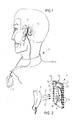
- An individual 2 (fig. 1, 2) is provided with an implant 3 for stimulating nerves (and/or muscle fibres) as is shown by curved broken lines 4.
- the implant 3 is supplied with energy and information by a transmitting member 6 provided behind the ear flap or oracle 5, said transmitting member fed by a signal processor 7 which processes sound received by a (not shown) microphone.
- the implant 3 (fig. 2) is provided with electronic components 8, 9, 10, 11 resp. and a coil or antenna 12. Electrical connections 13 of platinum or platinum iridium are used for supplying the required signals to an electrode. Arrows E show the radiated electro-magnetic energy, in which sound information is encoded.
- a package 14 of the implant 3 consists of e.g. two casing parts 15 and 16 of biocompatible glass, e.g. Borosilicate or lime glass of the Hermetronics Company from Slough in England.
- the parts 15 and 16 are sealed in a biocompatible way, e.g. by means of adhesive, laser welding, resist welding, ultrasonic welding or hot cap sealing. Conducts of the connections 13 through the package 14 are sintered.
- helium gas can be inserted, such that by means of a helium sniffer the seal can be checked on hermeticity. It is also possible not to bring this package into an atmosphere consisting of helium or another gas during some time period and afterwards to check for hermeticity outside this atmosphere (see e.g. Vakuumtechnik, Rudolf A. Lang Verlag, 627 Idstein, 23 (1974) volume 3, pages 77-80). A hermeticity of 10 ⁇ 8 mbar.l/s can easily be achieved; this is sufficient for implantation in the human or other living body.
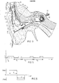
- an ear piece 20 which has the traditional shape to fit easily behind the ear 21 of a subject is provided with a lead 22 for connection at 23 to a rod shaped ear piece or mold 24, e.g. of plastic material and formed such as to be inserted into the auditory duct of the subject.
- This ear mold 24 inludes a (not shown) coil or inductor to be coupled with an inductor 26 to be implanted around the auditory duct 25.
- this conductor or coil 26 - diameter and height e.g. 2 mm, diameter of the windings e.g.
- the coil 26 is flexible by means of a layer of silicon around the windings, such as to prevent painful contact after implantation between ear piece 24 and coil 26.
- Conductor or coil 26 is connected by means of line 27 to implant 28 which consists of a housing 29 of titanium provided with a window 38 of glass or transparant plastic or ceramic material.
- the ear piece 20 is provided with a microphone 30. Electrical signals supplied by this microphone are fed through line 31 to a not shown speech processor (see e.g. fig. 2).
- This speech processor encodes information as required by the implant. This information is fed from the ear piece 20 opposite to the window 38 by means of a not shown infrared radiation emitting element 39 to the implant.
- This infrared radiation emitting element 39 is contacted directly to the skin.
- the required power for the IR-detector is only a few ⁇ Watt so that the emitting element 39 wil emit e.g. a few mWatt of power, but more emitting power will be possible without damaging the animate tissue.
- the IR-transmitter and IR-detector are aligned in a natural way by means of the ear and traditionally shaped ear piece and mold; there is no significant anatomical spread in different ear locations. Also the implant can easily be secured to the skull 33 of the subject. Pulses can be transmitted at the high rate, pulses having a width of less than 400 nsec are achievable.
- a lead 34 to an electrode 35 which is to be implanted in the cochlea of the deaf subject.
- the electrode 35 has branches (not shown) for stimulating different locations within the cochlea.
- the electrode is flexible and provided with a hook shaped end part (not shown) such as to be easily implantable into the cochlea by a surgeon. Stimulation is achieved through physiological fluid and nerve fibres 36.
- an antenna 37 Also there is connected to the implant 28 an antenna 37, the function of which will be described hereinafter.
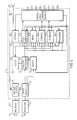
- Power from the lead 27 is rectified in rectifier 40 and fed to a voltage supply 41, which supplies voltage to all the different functional blocks within broken line 42, as is indicated by arrows A.
- the functions within broken line 42 are included in a custom integrated circuit especially designed for the system of the present invention.
- the infrared radiation is detected by detector 43 and fed to input monitor 44; in case the puls shape is not correct - e.g. if a spike occurs -, a signal is fed to reset 45 which resets the integrated circuit and prevents a stimulating current within the cochlea.
- a pulse accepted by the input monitor will be fed to a pulse sequence detection unit 46 which detects time intervals between pulses, as hereinafter will be more fully described.
- the first pulse determines at 46 the mode in which the system will operate
- the second pulse determines at 48 which of eight channels 51-58 of the electrode 35 will be activated, while at 49 the magnitude or quantity of the chosen channel is determined.
- the shape of the stimulating pulse is chosen by mode unit 47.
- Mode measuring is also chosen by mode unit 47 at 61.
- a signal is provided by output 62 to the antenna 37.
- Clock 32 provides clock signals for the circuit; the clock rate can be set before implantation between 250nsec- 2 ⁇ sec. The clock is synchronized at receiving each next accepted pulse.
- Fig. 5 shows an example of a pulse sequence to be transmitted by the ear piece and to be received by the IR-detector 43 (fig. 4).
- T0 is the period of one cycle of the clock 63 while P s designates the synchronizing pulse having a width of 4 ⁇ T0;
- T1 selects the mode (in this case biphasic see fig.
- T1 is between 2 ⁇ T0 and 4 ⁇ T0
- P m stands for mode selection pulse and a duration of 2 ⁇ T0
- T2 defines the channel to be activated, in this case channel 2, which means that T2 is in between 4 ⁇ T0 and 6 ⁇ T0
- P ch stands for channel selection pulse and has a duration of 2 ⁇ T0
- T3 defines the strenght of the stimulating pulse at channel 2, in this case e.g. 1,5 mA
- P cs has a width of 2 ⁇ T0.
- Fig. 6 shows a biphasic pulse with a duration ⁇ . and extending between V max and ⁇ V max in which ⁇ can be set before implantation and V max is determined by T3.
- the biphasic pulse is symmetric around the zero-axis, such that no charge will build up in the cochlea of the subject.
- the inverse of fig. 6 is called biphasic negative, in which the first edge of the pulse is going negative and the last edge is going downwardly.
- Other modes in which the system of the present invention can operate are so called normal modes (positive and negative) in which a constant current is supplied to two electrode branches, in which negative or positive decides which way the current will have to flow.
- a measuring signal to the antenna, giving an indication of the supply voltage at 41 or the measured voltage at a selected electrode.
- the signals have e.g. a frequency of 1 MHz and can be detected outside the subject, such that the surveillance of correct operation of the implant can be established.
- T1, T2 and T3 have a relatively large value, the relative spread in those values is approximately held constant, such that the allowed absolute spread in values to be detected is increased.
- the clock is only activated when the input monitor detects a synchronization pulse.
- Reset unit 45 provides in resetting the circuit of fig. 4 at missing one pulse, at erroneous detection of the synchronizing pulse, detection of decreasing power supply, and spikes occurring in the information supply. Therefore the described coding provides a very safe stimulating system, without inducing damaging current in an anminate body.
- the shown preferred embodiment for stimulating auditory nerves of a subject has external parts outside the animate body to be easily removed at e.g. swimming. It is expected that with this system a person having a good function of the auditory nerves will be able to comprehend speech.
- the system of the present invention uses coding in time sequence and the signal processing within the implant has a pipeline structure - not an operation according to the Von Neumann principle - a high rate of information transfer is achieved.
- IR-pulses can be made smaller than 400 nsec.
- the implant is again synchronized and reset.
- the shown embodiments show systems for stimulating nerves, but the present invention can also be used for stimulating muscles, e.g. hard muscles. The scope of protection is defined by the following claims:
Abstract
Description
- The present invention relates to a system of stimulating at least one nerve and/or muscle fibre of an animate subject according to the preamble of
claim 1. - An example of such a stimulating system for stimulating auditory nerves of a human being is known from IEEE Spectrum,
volume 21, No. 1, January 1984. In this known system a receiving unit mounted in the neighbourhood of the ear of a sensory or cochlear deaf person comprises a microphone to "hear" or capture sounds existing around the deaf person and a speech processing unit spaced from the ear and connected to the transmitting unit for processing the received sounds and for modulating waves to be transmitted to the implanted receiving section by the transmitting unit. - The present invention has for its object to provide a more accurate and versatile stimulating system.
- Therefore the present invention is characterized according to
claim 1. - The information supply means according to the present invention can comprise a receiver for radio frequency waves, but preferably comprise a detector for infrared radiation; the power supply means can comprise one or more batteries, but preferably comprise receiving means for radio frequency waves.
- A search of prior art disclosed the following references:
US-A-4.314.562,
IEEE Spectrum,volume 21, No. 1, January 1984,
US-A-4.142.532,
DE-A-28 23 798,
GB-A-2.134.335,
US-E-26809. - Preferred embodiments of the present invention are claimed in the subclaims; embodiments of the present invention will become clear on basis of the following description, including further advantages and details of the present invention, while referring to a drawing, in which are showing:
- fig. 1 a perspective view of a deaf subject provided with an implant according to the present invention;
- fig. 2 a perspective and diagrammatic view of the transfer of electro-magnetic waves to the implant of fig. 1;
- fig. 3 a view partly in section, partly in perspective of another preferred embodiment of the stimulating system of the present invention;
- fig. 4 a diagram illustrating the operation of the system of fig. 4;
- fig. 5 an example of a signal arriving at the implant of fig. 3; and
- fig. 6 an example of a stimulating signal.
- An individual 2 (fig. 1, 2) is provided with an
implant 3 for stimulating nerves (and/or muscle fibres) as is shown by curvedbroken lines 4. Theimplant 3 is supplied with energy and information by a transmittingmember 6 provided behind the ear flap or oracle 5, said transmitting member fed by asignal processor 7 which processes sound received by a (not shown) microphone. - The implant 3 (fig. 2) is provided with
electronic components antenna 12.Electrical connections 13 of platinum or platinum iridium are used for supplying the required signals to an electrode. Arrows E show the radiated electro-magnetic energy, in which sound information is encoded. - A
package 14 of theimplant 3 consists of e.g. twocasing parts parts connections 13 through thepackage 14 are sintered. - In the
package 14 helium gas can be inserted, such that by means of a helium sniffer the seal can be checked on hermeticity. It is also possible not to bring this package into an atmosphere consisting of helium or another gas during some time period and afterwards to check for hermeticity outside this atmosphere (see e.g. Vakuum Technik, Rudolf A. Lang Verlag, 627 Idstein, 23 (1974)volume 3, pages 77-80). A hermeticity of 10⁻⁸ mbar.l/s can easily be achieved; this is sufficient for implantation in the human or other living body. - In another preferred embodiment of the present invention (fig. 3) an
ear piece 20 which has the traditional shape to fit easily behind theear 21 of a subject is provided with alead 22 for connection at 23 to a rod shaped ear piece ormold 24, e.g. of plastic material and formed such as to be inserted into the auditory duct of the subject. Thisear mold 24 inludes a (not shown) coil or inductor to be coupled with aninductor 26 to be implanted around the auditory duct 25. Preferably this conductor or coil 26 - diameter and height e.g. 2 mm, diameter of the windings e.g. 0,7 mm - is conical, such as to fit around the inwardly tapering duct 25. Thecoil 26 is flexible by means of a layer of silicon around the windings, such as to prevent painful contact after implantation betweenear piece 24 andcoil 26. - By using the auditory duct 25 as site for transferring energy into the body of the subject, by means of radio frequency waves, e.g. of a frequency of 100 - 500 kHz, accurate alignment between the two inductors will always be provided. Conductor or
coil 26 is connected by means ofline 27 toimplant 28 which consists of ahousing 29 of titanium provided with awindow 38 of glass or transparant plastic or ceramic material. - The
ear piece 20 is provided with amicrophone 30. Electrical signals supplied by this microphone are fed throughline 31 to a not shown speech processor (see e.g. fig. 2). This speech processor encodes information as required by the implant. This information is fed from theear piece 20 opposite to thewindow 38 by means of a not shown infraredradiation emitting element 39 to the implant. This infraredradiation emitting element 39 is contacted directly to the skin. Although it appears almost form experiments that e.g. 30% or even 10% of this infrared radiation is lost in thetissue 32 before the window, the remaining part is sufficient to be detected behind thewindow 38 by means of an infrared radiation, without causing any damage to the tissue. The required power for the IR-detector is only a few µWatt so that theemitting element 39 wil emit e.g. a few mWatt of power, but more emitting power will be possible without damaging the animate tissue. The IR-transmitter and IR-detector are aligned in a natural way by means of the ear and traditionally shaped ear piece and mold; there is no significant anatomical spread in different ear locations. Also the implant can easily be secured to theskull 33 of the subject. Pulses can be transmitted at the high rate, pulses having a width of less than 400 nsec are achievable. - From the
implant 28 there is provided alead 34 to anelectrode 35 which is to be implanted in the cochlea of the deaf subject. Theelectrode 35 has branches (not shown) for stimulating different locations within the cochlea. the electrode is flexible and provided with a hook shaped end part (not shown) such as to be easily implantable into the cochlea by a surgeon. Stimulation is achieved through physiological fluid andnerve fibres 36. Also there is connected to theimplant 28 an antenna 37, the function of which will be described hereinafter. - Power from the lead 27 (fig. 4) is rectified in
rectifier 40 and fed to avoltage supply 41, which supplies voltage to all the different functional blocks withinbroken line 42, as is indicated by arrows A. The functions withinbroken line 42 are included in a custom integrated circuit especially designed for the system of the present invention. The infrared radiation is detected bydetector 43 and fed to inputmonitor 44; in case the puls shape is not correct - e.g. if a spike occurs -, a signal is fed to reset 45 which resets the integrated circuit and prevents a stimulating current within the cochlea. A pulse accepted by the input monitor will be fed to a pulsesequence detection unit 46 which detects time intervals between pulses, as hereinafter will be more fully described. The first pulse determines at 46 the mode in which the system will operate, the second pulse determines at 48 which of eight channels 51-58 of theelectrode 35 will be activated, while at 49 the magnitude or quantity of the chosen channel is determined. At 60 the shape of the stimulating pulse is chosen bymode unit 47. Mode measuring is also chosen bymode unit 47 at 61. In the measuring mode a signal is provided byoutput 62 to the antenna 37.Clock 32 provides clock signals for the circuit; the clock rate can be set before implantation between 250nsec- 2 µsec. The clock is synchronized at receiving each next accepted pulse. - Fig. 5 shows an example of a pulse sequence to be transmitted by the ear piece and to be received by the IR-detector 43 (fig. 4). T₀ is the period of one cycle of the
clock 63 while Ps designates the synchronizing pulse having a width of 4 × T₀; T₁ selects the mode (in this case biphasic see fig. 6), which means that T₁ is between 2 × T₀ and 4 × T₀); Pm stands for mode selection pulse and a duration of 2 × T₀; T₂ defines the channel to be activated, in thiscase channel 2, which means that T₂ is in between 4 × T₀ and 6 × T₀; Pch stands for channel selection pulse and has a duration of 2 × T₀; T₃ defines the strenght of the stimulating pulse atchannel 2, in this case e.g. 1,5 mA; Pcs has a width of 2 × T₀. - Fig. 6 shows a biphasic pulse with a duration τ. and extending between Vmax and ⁻Vmax in which τ can be set before implantation and Vmax is determined by T₃. The biphasic pulse is symmetric around the zero-axis, such that no charge will build up in the cochlea of the subject. The inverse of fig. 6 is called biphasic negative, in which the first edge of the pulse is going negative and the last edge is going downwardly. Other modes in which the system of the present invention can operate are so called normal modes (positive and negative) in which a constant current is supplied to two electrode branches, in which negative or positive decides which way the current will have to flow.
- In the measuring mode there is supplied a measuring signal to the antenna, giving an indication of the supply voltage at 41 or the measured voltage at a selected electrode. The signals have e.g. a frequency of 1 MHz and can be detected outside the subject, such that the surveillance of correct operation of the implant can be established. When T₁, T₂ and T₃ have a relatively large value, the relative spread in those values is approximately held constant, such that the allowed absolute spread in values to be detected is increased.
- The clock is only activated when the input monitor detects a synchronization pulse.
-
Reset unit 45 provides in resetting the circuit of fig. 4 at missing one pulse, at erroneous detection of the synchronizing pulse, detection of decreasing power supply, and spikes occurring in the information supply. Therefore the described coding provides a very safe stimulating system, without inducing damaging current in an anminate body. - The shown preferred embodiment for stimulating auditory nerves of a subject has external parts outside the animate body to be easily removed at e.g. swimming. It is expected that with this system a person having a good function of the auditory nerves will be able to comprehend speech.
- As the system of the present invention uses coding in time sequence and the signal processing within the implant has a pipeline structure - not an operation according to the Von Neumann principle - a high rate of information transfer is achieved. IR-pulses can be made smaller than 400 nsec. At each sequence the implant is again synchronized and reset. The shown embodiments show systems for stimulating nerves, but the present invention can also be used for stimulating muscles, e.g. hard muscles. The scope of protection is defined by the following claims:
Claims (20)
Priority Applications (2)
| Application Number | Priority Date | Filing Date | Title |
|---|---|---|---|
| AT87201505T ATE96294T1 (en) | 1986-08-08 | 1987-08-06 | SYSTEM FOR STIMULATING AT LEAST ONE NERVE AND/OR MUSCLE FIBER. |
| JP63044051A JPS6443252A (en) | 1987-08-06 | 1988-02-25 | Stimulation system, housing, embedding, data processing circuit, ear pad ear model, electrode and coil |
Applications Claiming Priority (2)
| Application Number | Priority Date | Filing Date | Title |
|---|---|---|---|
| NL8602043A NL8602043A (en) | 1986-08-08 | 1986-08-08 | METHOD FOR PACKING AN IMPLANT, FOR example AN ELECTRONIC CIRCUIT, PACKAGING AND IMPLANT. |
| NL8602043 | 1986-08-08 |
Publications (3)
| Publication Number | Publication Date |
|---|---|
| EP0259906A2 true EP0259906A2 (en) | 1988-03-16 |
| EP0259906A3 EP0259906A3 (en) | 1989-07-19 |
| EP0259906B1 EP0259906B1 (en) | 1993-10-27 |
Family
ID=19848391
Family Applications (1)
| Application Number | Title | Priority Date | Filing Date |
|---|---|---|---|
| EP87201505A Expired - Lifetime EP0259906B1 (en) | 1986-08-08 | 1987-08-06 | A system of stimulating at least one nerve and/or muscle fibre |
Country Status (5)
| Country | Link |
|---|---|
| US (1) | US4932405A (en) |
| EP (1) | EP0259906B1 (en) |
| AT (1) | ATE96294T1 (en) |
| DE (1) | DE3787944T2 (en) |
| NL (1) | NL8602043A (en) |
Cited By (15)
| Publication number | Priority date | Publication date | Assignee | Title |
|---|---|---|---|---|
| AU605343B2 (en) * | 1987-07-24 | 1991-01-10 | Cochlear Limited | Apparatus and method for insertion of cochlear electrode assembly |
| WO1994017645A1 (en) * | 1993-01-25 | 1994-08-04 | Auditory Micromachines, Inc. | Implantable auditory system with micromachined microsensor and microactuator |
| WO1995021591A1 (en) * | 1994-02-09 | 1995-08-17 | University Of Iowa Research Foundation | Human cerebral cortex neural prosthetic |
| US5496369A (en) * | 1994-02-09 | 1996-03-05 | University Of Iowa Research Foundation | Human cerebral cortex neural prosthetic |
| US5676655A (en) * | 1994-02-09 | 1997-10-14 | University Of Iowa Research Foundation | Methods for treating tinnitus by drug microinfusion from a neural prosthesis inserted in the brain |
| US5772575A (en) * | 1995-09-22 | 1998-06-30 | S. George Lesinski | Implantable hearing aid |
| US5800535A (en) * | 1994-02-09 | 1998-09-01 | The University Of Iowa Research Foundation | Wireless prosthetic electrode for the brain |
| US5881158A (en) * | 1996-05-24 | 1999-03-09 | United States Surgical Corporation | Microphones for an implantable hearing aid |
| US5951601A (en) * | 1996-03-25 | 1999-09-14 | Lesinski; S. George | Attaching an implantable hearing aid microactuator |
| US5977689A (en) * | 1996-07-19 | 1999-11-02 | Neukermans; Armand P. | Biocompatible, implantable hearing aid microactuator |
| US6129685A (en) * | 1994-02-09 | 2000-10-10 | The University Of Iowa Research Foundation | Stereotactic hypothalamic obesity probe |
| US7077822B1 (en) | 1994-02-09 | 2006-07-18 | The University Of Iowa Research Foundation | Stereotactic hypothalamic obesity probe |
| EP2274923A1 (en) * | 2008-04-11 | 2011-01-19 | Nurobiosys | A cochlea implant system in ite (in the ear) type using infrared data communication |
| WO2011068822A3 (en) * | 2009-12-01 | 2011-09-09 | Med-El Elektromedizinische Geraete Gmbh | Inductive signal and energy transfer through the external auditory canal |
| US10940320B2 (en) | 2014-06-02 | 2021-03-09 | Cochlear Limited | Distributed implantable hearing systems |
Families Citing this family (70)
| Publication number | Priority date | Publication date | Assignee | Title |
|---|---|---|---|---|
| CA1331803C (en) * | 1988-12-21 | 1994-08-30 | Murray A. Davis | Hearing aid |
| DE69011753T2 (en) * | 1989-06-07 | 1995-02-16 | Assistance Publique | Transcutaneous connection device. |
| US5876425A (en) * | 1989-09-22 | 1999-03-02 | Advanced Bionics Corporation | Power control loop for implantable tissue stimulator |
| US5531774A (en) * | 1989-09-22 | 1996-07-02 | Alfred E. Mann Foundation For Scientific Research | Multichannel implantable cochlear stimulator having programmable bipolar, monopolar or multipolar electrode configurations |
| US5603726A (en) * | 1989-09-22 | 1997-02-18 | Alfred E. Mann Foundation For Scientific Research | Multichannel cochlear implant system including wearable speech processor |
| US5314458A (en) * | 1990-06-01 | 1994-05-24 | University Of Michigan | Single channel microstimulator |
| EP0578752B1 (en) * | 1991-04-01 | 1997-09-03 | Resound Corporation | Inconspicuous communication method utilizing remote electromagnetic drive |
| US5425752A (en) * | 1991-11-25 | 1995-06-20 | Vu'nguyen; Dung D. | Method of direct electrical myostimulation using acupuncture needles |
| US5476494A (en) * | 1992-09-11 | 1995-12-19 | Massachusetts Institute Of Technology | Low pressure neural contact structure |
| US5797854A (en) * | 1995-08-01 | 1998-08-25 | Hedgecock; James L. | Method and apparatus for testing and measuring current perception threshold and motor nerve junction performance |
| AU5478298A (en) * | 1997-01-13 | 1998-08-03 | Neurodan A/S | An implantable nerve stimulator electrode |
| US5991664A (en) * | 1997-03-09 | 1999-11-23 | Cochlear Limited | Compact inductive arrangement for medical implant data and power transfer |
| USD419677S (en) * | 1997-11-04 | 2000-01-25 | Med-El Elektromedizinische Gerate Ges.M.B.H. | Speech processor for use with a cochlear implant |
| US6907130B1 (en) * | 1998-02-13 | 2005-06-14 | University Of Iowa Research Foundation | Speech processing system and method using pseudospontaneous stimulation |
| RU2226358C2 (en) * | 1998-09-04 | 2004-04-10 | Уолф Рисерч Пти. Лтд. | Medical implant system |
| US6516227B1 (en) | 1999-07-27 | 2003-02-04 | Advanced Bionics Corporation | Rechargeable spinal cord stimulator system |
| DE10015421C2 (en) * | 2000-03-28 | 2002-07-04 | Implex Ag Hearing Technology I | Partially or fully implantable hearing system |
| AU2001268142B2 (en) * | 2000-06-01 | 2006-05-18 | Otologics, Llc | Method and apparatus for measuring the performance of an implantable middle ear hearing aid, and the response of patient wearing such a hearing aid |
| US6707920B2 (en) | 2000-12-12 | 2004-03-16 | Otologics Llc | Implantable hearing aid microphone |
| AU2002342150A1 (en) | 2001-10-30 | 2003-05-12 | George S. Lesinski | Implantation method for a hearing aid microactuator implanted into the cochlea |
| US7529587B2 (en) | 2003-10-13 | 2009-05-05 | Cochlear Limited | External speech processor unit for an auditory prosthesis |
| US7556597B2 (en) * | 2003-11-07 | 2009-07-07 | Otologics, Llc | Active vibration attenuation for implantable microphone |
| US7204799B2 (en) * | 2003-11-07 | 2007-04-17 | Otologics, Llc | Microphone optimized for implant use |
| US20050137652A1 (en) * | 2003-12-19 | 2005-06-23 | The Board of Regents of the University of Texas at Dallas | System and method for interfacing cellular matter with a machine |
| US20090198293A1 (en) * | 2003-12-19 | 2009-08-06 | Lawrence Cauller | Microtransponder Array for Implant |
| US7840020B1 (en) | 2004-04-01 | 2010-11-23 | Otologics, Llc | Low acceleration sensitivity microphone |
| US7214179B2 (en) * | 2004-04-01 | 2007-05-08 | Otologics, Llc | Low acceleration sensitivity microphone |
| US8295523B2 (en) | 2007-10-04 | 2012-10-23 | SoundBeam LLC | Energy delivery and microphone placement methods for improved comfort in an open canal hearing aid |
| US7867160B2 (en) | 2004-10-12 | 2011-01-11 | Earlens Corporation | Systems and methods for photo-mechanical hearing transduction |
| US7668325B2 (en) | 2005-05-03 | 2010-02-23 | Earlens Corporation | Hearing system having an open chamber for housing components and reducing the occlusion effect |
| WO2006076531A2 (en) * | 2005-01-11 | 2006-07-20 | Otologics, Llc | Active vibration attenuation for implantable microphone |
| US8096937B2 (en) | 2005-01-11 | 2012-01-17 | Otologics, Llc | Adaptive cancellation system for implantable hearing instruments |
| US7582052B2 (en) * | 2005-04-27 | 2009-09-01 | Otologics, Llc | Implantable hearing aid actuator positioning |
| US7489793B2 (en) * | 2005-07-08 | 2009-02-10 | Otologics, Llc | Implantable microphone with shaped chamber |
| US7522738B2 (en) * | 2005-11-30 | 2009-04-21 | Otologics, Llc | Dual feedback control system for implantable hearing instrument |
| US9693708B2 (en) * | 2007-05-04 | 2017-07-04 | Arizona Board Of Regents For And On Behalf Of Arizona State University | Systems and methods for wireless transmission of biopotentials |
| US7630771B2 (en) * | 2007-06-25 | 2009-12-08 | Microtransponder, Inc. | Grooved electrode and wireless microtransponder system |
| EP2208367B1 (en) | 2007-10-12 | 2017-09-27 | Earlens Corporation | Multifunction system and method for integrated hearing and communiction with noise cancellation and feedback management |
| US8472654B2 (en) | 2007-10-30 | 2013-06-25 | Cochlear Limited | Observer-based cancellation system for implantable hearing instruments |
| AU2008329652B2 (en) * | 2007-11-26 | 2011-08-04 | Micro Transponder Inc. | Implanted driver with resistive charge balancing |
| WO2009070705A2 (en) * | 2007-11-26 | 2009-06-04 | Microtransponder Inc. | Transfer coil architecture |
| US8457757B2 (en) | 2007-11-26 | 2013-06-04 | Micro Transponder, Inc. | Implantable transponder systems and methods |
| US9089707B2 (en) | 2008-07-02 | 2015-07-28 | The Board Of Regents, The University Of Texas System | Systems, methods and devices for paired plasticity |
| US8396239B2 (en) | 2008-06-17 | 2013-03-12 | Earlens Corporation | Optical electro-mechanical hearing devices with combined power and signal architectures |
| WO2009155361A1 (en) | 2008-06-17 | 2009-12-23 | Earlens Corporation | Optical electro-mechanical hearing devices with combined power and signal architectures |
| DK2301261T3 (en) | 2008-06-17 | 2019-04-23 | Earlens Corp | Optical electromechanical hearing aids with separate power supply and signal components |
| KR101717034B1 (en) | 2008-09-22 | 2017-03-15 | 이어렌즈 코포레이션 | Balanced armature devices and methods for hearing |
| WO2010138911A1 (en) | 2009-05-29 | 2010-12-02 | Otologics, Llc | Implantable auditory stimulation system and method with offset implanted microphones |
| WO2010141895A1 (en) | 2009-06-05 | 2010-12-09 | SoundBeam LLC | Optically coupled acoustic middle ear implant systems and methods |
| US9544700B2 (en) | 2009-06-15 | 2017-01-10 | Earlens Corporation | Optically coupled active ossicular replacement prosthesis |
| EP2443843A4 (en) | 2009-06-18 | 2013-12-04 | SoundBeam LLC | Eardrum implantable devices for hearing systems and methods |
| WO2010148324A1 (en) * | 2009-06-18 | 2010-12-23 | SoundBeam LLC | Optically coupled cochlear implant systems and methods |
| US10555100B2 (en) | 2009-06-22 | 2020-02-04 | Earlens Corporation | Round window coupled hearing systems and methods |
| WO2011005479A2 (en) | 2009-06-22 | 2011-01-13 | SoundBeam LLC | Optically coupled bone conduction systems and methods |
| US8845705B2 (en) | 2009-06-24 | 2014-09-30 | Earlens Corporation | Optical cochlear stimulation devices and methods |
| US8715154B2 (en) | 2009-06-24 | 2014-05-06 | Earlens Corporation | Optically coupled cochlear actuator systems and methods |
| EP2656639B1 (en) | 2010-12-20 | 2020-05-13 | Earlens Corporation | Anatomically customized ear canal hearing apparatus |
| US10034103B2 (en) | 2014-03-18 | 2018-07-24 | Earlens Corporation | High fidelity and reduced feedback contact hearing apparatus and methods |
| WO2016011044A1 (en) | 2014-07-14 | 2016-01-21 | Earlens Corporation | Sliding bias and peak limiting for optical hearing devices |
| US9924276B2 (en) | 2014-11-26 | 2018-03-20 | Earlens Corporation | Adjustable venting for hearing instruments |
| US10284968B2 (en) | 2015-05-21 | 2019-05-07 | Cochlear Limited | Advanced management of an implantable sound management system |
| DK3355801T3 (en) | 2015-10-02 | 2021-06-21 | Earlens Corp | Adapted ear canal device for drug delivery |
| US10492010B2 (en) | 2015-12-30 | 2019-11-26 | Earlens Corporations | Damping in contact hearing systems |
| US10306381B2 (en) | 2015-12-30 | 2019-05-28 | Earlens Corporation | Charging protocol for rechargable hearing systems |
| US11350226B2 (en) | 2015-12-30 | 2022-05-31 | Earlens Corporation | Charging protocol for rechargeable hearing systems |
| US11071869B2 (en) | 2016-02-24 | 2021-07-27 | Cochlear Limited | Implantable device having removable portion |
| CN112738700A (en) | 2016-09-09 | 2021-04-30 | 伊尔兰斯公司 | Smart mirror system and method |
| WO2018093733A1 (en) | 2016-11-15 | 2018-05-24 | Earlens Corporation | Improved impression procedure |
| WO2019173470A1 (en) | 2018-03-07 | 2019-09-12 | Earlens Corporation | Contact hearing device and retention structure materials |
| WO2019199680A1 (en) | 2018-04-09 | 2019-10-17 | Earlens Corporation | Dynamic filter |
Citations (10)
| Publication number | Priority date | Publication date | Assignee | Title |
|---|---|---|---|---|
| US3672352A (en) * | 1969-04-09 | 1972-06-27 | George D Summers | Implantable bio-data monitoring method and apparatus |
| US3945387A (en) * | 1974-09-09 | 1976-03-23 | General Electric Company | Implantable cardiac pacer with characteristic controllable circuit and control device therefor |
| DE2750164A1 (en) * | 1977-11-09 | 1979-05-10 | Michael S Dipl Ing Lampadius | PACEMAKER |
| US4301814A (en) * | 1977-04-26 | 1981-11-24 | Meer Sneer | Cassette implant |
| GB2134335A (en) * | 1983-01-27 | 1984-08-08 | Commw Of Australia | Sealed electrical connector for cochlear prosthetic package |
| US4545381A (en) * | 1984-10-01 | 1985-10-08 | Cordis Corporation | Adapter for converting a metal encapsulated implantable cardiac pacer to an externally worn cardiac pacer |
| EP0179536A2 (en) * | 1984-10-22 | 1986-04-30 | Cochlear Pty., Ltd. | Improvements in power transfer for implanted prostheses |
| EP0193145A2 (en) * | 1985-02-26 | 1986-09-03 | Hortmann GmbH | Transmission system for auditory prostheses |
| US4677982A (en) * | 1981-12-31 | 1987-07-07 | New York University | Infrared transcutaneous communicator and method of using same |
| DD252319A1 (en) * | 1986-08-04 | 1987-12-16 | Zentralinstitut Fuer Diabetes | IMPLANTABLE INFUSION PUMP |
Family Cites Families (9)
| Publication number | Priority date | Publication date | Assignee | Title |
|---|---|---|---|---|
| US26809A (en) * | 1860-01-10 | Henry belfield | ||
| US4314562A (en) * | 1977-05-04 | 1982-02-09 | Medtronic, Inc. | Enclosure system for body implantable electrical systems |
| US4142532A (en) * | 1978-04-07 | 1979-03-06 | Medtronic, Inc. | Body implantable stimulator with novel connector and method |
| DE2823798C2 (en) * | 1978-05-31 | 1980-07-03 | Siemens Ag, 1000 Berlin Und 8000 Muenchen | Method for electrical stimulation of the auditory nerve and multi-channel hearing prosthesis for carrying out the method |
| US4532930A (en) * | 1983-04-11 | 1985-08-06 | Commonwealth Of Australia, Dept. Of Science & Technology | Cochlear implant system for an auditory prosthesis |
| US4592359A (en) * | 1985-04-02 | 1986-06-03 | The Board Of Trustees Of The Leland Stanford Junior University | Multi-channel implantable neural stimulator |
| US4606329A (en) * | 1985-05-22 | 1986-08-19 | Xomed, Inc. | Implantable electromagnetic middle-ear bone-conduction hearing aid device |
| US4612915A (en) * | 1985-05-23 | 1986-09-23 | Xomed, Inc. | Direct bone conduction hearing aid device |
| US4741340A (en) * | 1985-12-18 | 1988-05-03 | Cordis Corporation | Pulse to sinewave telemetry system |
-
1986
- 1986-08-08 NL NL8602043A patent/NL8602043A/en not_active Application Discontinuation
-
1987
- 1987-08-06 AT AT87201505T patent/ATE96294T1/en active
- 1987-08-06 EP EP87201505A patent/EP0259906B1/en not_active Expired - Lifetime
- 1987-08-06 DE DE87201505T patent/DE3787944T2/en not_active Expired - Fee Related
- 1987-08-07 US US07/082,548 patent/US4932405A/en not_active Expired - Fee Related
Patent Citations (10)
| Publication number | Priority date | Publication date | Assignee | Title |
|---|---|---|---|---|
| US3672352A (en) * | 1969-04-09 | 1972-06-27 | George D Summers | Implantable bio-data monitoring method and apparatus |
| US3945387A (en) * | 1974-09-09 | 1976-03-23 | General Electric Company | Implantable cardiac pacer with characteristic controllable circuit and control device therefor |
| US4301814A (en) * | 1977-04-26 | 1981-11-24 | Meer Sneer | Cassette implant |
| DE2750164A1 (en) * | 1977-11-09 | 1979-05-10 | Michael S Dipl Ing Lampadius | PACEMAKER |
| US4677982A (en) * | 1981-12-31 | 1987-07-07 | New York University | Infrared transcutaneous communicator and method of using same |
| GB2134335A (en) * | 1983-01-27 | 1984-08-08 | Commw Of Australia | Sealed electrical connector for cochlear prosthetic package |
| US4545381A (en) * | 1984-10-01 | 1985-10-08 | Cordis Corporation | Adapter for converting a metal encapsulated implantable cardiac pacer to an externally worn cardiac pacer |
| EP0179536A2 (en) * | 1984-10-22 | 1986-04-30 | Cochlear Pty., Ltd. | Improvements in power transfer for implanted prostheses |
| EP0193145A2 (en) * | 1985-02-26 | 1986-09-03 | Hortmann GmbH | Transmission system for auditory prostheses |
| DD252319A1 (en) * | 1986-08-04 | 1987-12-16 | Zentralinstitut Fuer Diabetes | IMPLANTABLE INFUSION PUMP |
Non-Patent Citations (1)
| Title |
|---|
| Medical & Biological Engineering and Computing, Vol. 23, No. 4, July 1985, pages 387-389; Stevenage, Herts, GB, M. TAKAHASHI et al.: "Near infrared telemetry system". * |
Cited By (27)
| Publication number | Priority date | Publication date | Assignee | Title |
|---|---|---|---|---|
| AU605343B2 (en) * | 1987-07-24 | 1991-01-10 | Cochlear Limited | Apparatus and method for insertion of cochlear electrode assembly |
| US5531787A (en) * | 1993-01-25 | 1996-07-02 | Lesinski; S. George | Implantable auditory system with micromachined microsensor and microactuator |
| WO1994017645A1 (en) * | 1993-01-25 | 1994-08-04 | Auditory Micromachines, Inc. | Implantable auditory system with micromachined microsensor and microactuator |
| US5984859A (en) * | 1993-01-25 | 1999-11-16 | Lesinski; S. George | Implantable auditory system components and system |
| US6456886B1 (en) | 1994-02-09 | 2002-09-24 | University Of Iowa Research Foundation | Human cerabal cortex neural prosthetic for tinnitus |
| US5496369A (en) * | 1994-02-09 | 1996-03-05 | University Of Iowa Research Foundation | Human cerebral cortex neural prosthetic |
| US5697975A (en) * | 1994-02-09 | 1997-12-16 | The University Of Iowa Research Foundation | Human cerebral cortex neural prosthetic for tinnitus |
| US5713847A (en) * | 1994-02-09 | 1998-02-03 | The University Of Iowa Research Foundation | Human drug delivery device for tinnitus |
| US5735885A (en) * | 1994-02-09 | 1998-04-07 | The University Of Iowa Research Foundation | Methods for implanting neural prosthetic for tinnitus |
| US7077822B1 (en) | 1994-02-09 | 2006-07-18 | The University Of Iowa Research Foundation | Stereotactic hypothalamic obesity probe |
| US5800535A (en) * | 1994-02-09 | 1998-09-01 | The University Of Iowa Research Foundation | Wireless prosthetic electrode for the brain |
| US5820588A (en) * | 1994-02-09 | 1998-10-13 | The University Of Iowa Research Foundation | Method for passing information between a patient's auditory cortex and a speech processor |
| WO1995021591A1 (en) * | 1994-02-09 | 1995-08-17 | University Of Iowa Research Foundation | Human cerebral cortex neural prosthetic |
| US6129685A (en) * | 1994-02-09 | 2000-10-10 | The University Of Iowa Research Foundation | Stereotactic hypothalamic obesity probe |
| US5676655A (en) * | 1994-02-09 | 1997-10-14 | University Of Iowa Research Foundation | Methods for treating tinnitus by drug microinfusion from a neural prosthesis inserted in the brain |
| US5772575A (en) * | 1995-09-22 | 1998-06-30 | S. George Lesinski | Implantable hearing aid |
| US5951601A (en) * | 1996-03-25 | 1999-09-14 | Lesinski; S. George | Attaching an implantable hearing aid microactuator |
| US5881158A (en) * | 1996-05-24 | 1999-03-09 | United States Surgical Corporation | Microphones for an implantable hearing aid |
| US5977689A (en) * | 1996-07-19 | 1999-11-02 | Neukermans; Armand P. | Biocompatible, implantable hearing aid microactuator |
| US6153966A (en) * | 1996-07-19 | 2000-11-28 | Neukermans; Armand P. | Biocompatible, implantable hearing aid microactuator |
| EP2274923A1 (en) * | 2008-04-11 | 2011-01-19 | Nurobiosys | A cochlea implant system in ite (in the ear) type using infrared data communication |
| EP2274923A4 (en) * | 2008-04-11 | 2012-01-04 | Nurobiosys | A cochlea implant system in ite (in the ear) type using infrared data communication |
| AU2008354445B2 (en) * | 2008-04-11 | 2014-01-23 | M.I. Tech Co., Ltd. | A cochlea implant system in ITE (in the ear) type using infrared data communication |
| WO2011068822A3 (en) * | 2009-12-01 | 2011-09-09 | Med-El Elektromedizinische Geraete Gmbh | Inductive signal and energy transfer through the external auditory canal |
| AU2010326144B2 (en) * | 2009-12-01 | 2013-10-24 | Med-El Elektromedizinische Geraete Gmbh | Inductive signal and energy transfer through the external auditory canal |
| US9802043B2 (en) | 2009-12-01 | 2017-10-31 | Med-El Elektromedizinische Geraete Gmbh | Inductive signal and energy transfer through the external auditory canal |
| US10940320B2 (en) | 2014-06-02 | 2021-03-09 | Cochlear Limited | Distributed implantable hearing systems |
Also Published As
| Publication number | Publication date |
|---|---|
| DE3787944T2 (en) | 1994-02-17 |
| NL8602043A (en) | 1988-03-01 |
| EP0259906B1 (en) | 1993-10-27 |
| DE3787944D1 (en) | 1993-12-02 |
| ATE96294T1 (en) | 1993-11-15 |
| US4932405A (en) | 1990-06-12 |
| EP0259906A3 (en) | 1989-07-19 |
Similar Documents
| Publication | Publication Date | Title |
|---|---|---|
| EP0259906B1 (en) | A system of stimulating at least one nerve and/or muscle fibre | |
| US5749912A (en) | Low-cost, four-channel cochlear implant | |
| US7346397B2 (en) | Cochlear implant | |
| EP2274923B1 (en) | A cochlea implant system in ite (in the ear) type using infrared data communication | |
| US6648914B2 (en) | Totally implantable cochlear prosthesis | |
| US5571148A (en) | Implantable multichannel stimulator | |
| AU782132B2 (en) | Cochlear implant system partially insertable in the external ear | |
| US8478416B2 (en) | Implant power control | |
| US20110112355A1 (en) | Implantable sound sensor for hearing prostheses | |
| WO2003092326A1 (en) | Mri-compatible cochlear implant | |
| JPS621726B2 (en) | ||
| Clark et al. | A multi-channel hearing prosthesis for profound-to-total hearing loss | |
| US7873420B2 (en) | Password protection for cochlear implant | |
| AU2010319699B2 (en) | Implant power system | |
| US20060178720A1 (en) | Method and apparatus for sealing a lumen in an electrode assembly | |
| Peeters et al. | Cochlear implants: the LAURA prosthesis | |
| US11904167B2 (en) | Auxiliary device connection | |
| AU2007202342A1 (en) | Cochlear implant | |
| AU2003287772A1 (en) | Method and apparatus for sealing a lumen in an electrode assembly |
Legal Events
| Date | Code | Title | Description |
|---|---|---|---|
| PUAI | Public reference made under article 153(3) epc to a published international application that has entered the european phase |
Free format text: ORIGINAL CODE: 0009012 |
|
| AK | Designated contracting states |
Kind code of ref document: A2 Designated state(s): AT BE CH DE ES FR GB GR IT LI LU NL SE |
|
| PUAL | Search report despatched |
Free format text: ORIGINAL CODE: 0009013 |
|
| AK | Designated contracting states |
Kind code of ref document: A3 Designated state(s): AT BE CH DE ES FR GB GR IT LI LU NL SE |
|
| 17P | Request for examination filed |
Effective date: 19891019 |
|
| 17Q | First examination report despatched |
Effective date: 19910208 |
|
| GRAA | (expected) grant |
Free format text: ORIGINAL CODE: 0009210 |
|
| AK | Designated contracting states |
Kind code of ref document: B1 Designated state(s): AT BE CH DE ES FR GB GR IT LI LU NL SE |
|
| PG25 | Lapsed in a contracting state [announced via postgrant information from national office to epo] |
Ref country code: SE Effective date: 19931027 Ref country code: IT Free format text: LAPSE BECAUSE OF FAILURE TO SUBMIT A TRANSLATION OF THE DESCRIPTION OR TO PAY THE FEE WITHIN THE PRE;WARNING: LAPSES OF ITALIAN PATENTS WITH EFFECTIVE DATE BEFORE 2007 MAY HAVE OCCURRED AT ANY TIME BEFORE 2007. THE CORRECT EFFECTIVE DATE MAY BE DIFFERENT FROM THE ONE RECORDED.SCRIBED TIME-LIMIT Effective date: 19931027 Ref country code: NL Effective date: 19931027 Ref country code: BE Effective date: 19931027 Ref country code: CH Effective date: 19931027 Ref country code: GR Free format text: LAPSE BECAUSE OF FAILURE TO SUBMIT A TRANSLATION OF THE DESCRIPTION OR TO PAY THE FEE WITHIN THE PRESCRIBED TIME-LIMIT Effective date: 19931027 Ref country code: AT Effective date: 19931027 Ref country code: LI Effective date: 19931027 |
|
| REF | Corresponds to: |
Ref document number: 96294 Country of ref document: AT Date of ref document: 19931115 Kind code of ref document: T |
|
| REF | Corresponds to: |
Ref document number: 3787944 Country of ref document: DE Date of ref document: 19931202 |
|
| ET | Fr: translation filed | ||
| REG | Reference to a national code |
Ref country code: CH Ref legal event code: PL |
|
| PG25 | Lapsed in a contracting state [announced via postgrant information from national office to epo] |
Ref country code: ES Free format text: LAPSE BECAUSE OF FAILURE TO SUBMIT A TRANSLATION OF THE DESCRIPTION OR TO PAY THE FEE WITHIN THE PRESCRIBED TIME-LIMIT Effective date: 19940207 |
|
| NLV1 | Nl: lapsed or annulled due to failure to fulfill the requirements of art. 29p and 29m of the patents act | ||
| PGFP | Annual fee paid to national office [announced via postgrant information from national office to epo] |
Ref country code: GB Payment date: 19940725 Year of fee payment: 8 |
|
| PLBE | No opposition filed within time limit |
Free format text: ORIGINAL CODE: 0009261 |
|
| STAA | Information on the status of an ep patent application or granted ep patent |
Free format text: STATUS: NO OPPOSITION FILED WITHIN TIME LIMIT |
|
| PG25 | Lapsed in a contracting state [announced via postgrant information from national office to epo] |
Ref country code: LU Free format text: LAPSE BECAUSE OF NON-PAYMENT OF DUE FEES Effective date: 19940831 |
|
| PGFP | Annual fee paid to national office [announced via postgrant information from national office to epo] |
Ref country code: FR Payment date: 19940831 Year of fee payment: 8 |
|
| PGFP | Annual fee paid to national office [announced via postgrant information from national office to epo] |
Ref country code: DE Payment date: 19940930 Year of fee payment: 8 |
|
| 26N | No opposition filed | ||
| PG25 | Lapsed in a contracting state [announced via postgrant information from national office to epo] |
Ref country code: GB Effective date: 19950806 |
|
| GBPC | Gb: european patent ceased through non-payment of renewal fee |
Effective date: 19950806 |
|
| PG25 | Lapsed in a contracting state [announced via postgrant information from national office to epo] |
Ref country code: FR Effective date: 19960430 |
|
| PG25 | Lapsed in a contracting state [announced via postgrant information from national office to epo] |
Ref country code: DE Effective date: 19960501 |
|
| REG | Reference to a national code |
Ref country code: FR Ref legal event code: ST |