EP0261317A2 - Check valve device - Google Patents
Check valve device Download PDFInfo
- Publication number
- EP0261317A2 EP0261317A2 EP19870108969 EP87108969A EP0261317A2 EP 0261317 A2 EP0261317 A2 EP 0261317A2 EP 19870108969 EP19870108969 EP 19870108969 EP 87108969 A EP87108969 A EP 87108969A EP 0261317 A2 EP0261317 A2 EP 0261317A2
- Authority
- EP
- European Patent Office
- Prior art keywords
- check valve
- valve device
- legs
- housing
- bracket
- Prior art date
- Legal status (The legal status is an assumption and is not a legal conclusion. Google has not performed a legal analysis and makes no representation as to the accuracy of the status listed.)
- Granted
Links
Images
Classifications
-
- A—HUMAN NECESSITIES
- A61—MEDICAL OR VETERINARY SCIENCE; HYGIENE
- A61M—DEVICES FOR INTRODUCING MEDIA INTO, OR ONTO, THE BODY; DEVICES FOR TRANSDUCING BODY MEDIA OR FOR TAKING MEDIA FROM THE BODY; DEVICES FOR PRODUCING OR ENDING SLEEP OR STUPOR
- A61M39/00—Tubes, tube connectors, tube couplings, valves, access sites or the like, specially adapted for medical use
- A61M39/22—Valves or arrangement of valves
- A61M39/26—Valves closing automatically on disconnecting the line and opening on reconnection thereof
-
- F—MECHANICAL ENGINEERING; LIGHTING; HEATING; WEAPONS; BLASTING
- F16—ENGINEERING ELEMENTS AND UNITS; GENERAL MEASURES FOR PRODUCING AND MAINTAINING EFFECTIVE FUNCTIONING OF MACHINES OR INSTALLATIONS; THERMAL INSULATION IN GENERAL
- F16K—VALVES; TAPS; COCKS; ACTUATING-FLOATS; DEVICES FOR VENTING OR AERATING
- F16K15/00—Check valves
- F16K15/14—Check valves with flexible valve members
- F16K15/148—Check valves with flexible valve members the closure elements being fixed in their centre
-
- F—MECHANICAL ENGINEERING; LIGHTING; HEATING; WEAPONS; BLASTING
- F16—ENGINEERING ELEMENTS AND UNITS; GENERAL MEASURES FOR PRODUCING AND MAINTAINING EFFECTIVE FUNCTIONING OF MACHINES OR INSTALLATIONS; THERMAL INSULATION IN GENERAL
- F16K—VALVES; TAPS; COCKS; ACTUATING-FLOATS; DEVICES FOR VENTING OR AERATING
- F16K15/00—Check valves
- F16K15/18—Check valves with actuating mechanism; Combined check valves and actuated valves
- F16K15/182—Check valves with actuating mechanism; Combined check valves and actuated valves with actuating mechanism
- F16K15/1825—Check valves with actuating mechanism; Combined check valves and actuated valves with actuating mechanism for check valves with flexible valve members
-
- Y—GENERAL TAGGING OF NEW TECHNOLOGICAL DEVELOPMENTS; GENERAL TAGGING OF CROSS-SECTIONAL TECHNOLOGIES SPANNING OVER SEVERAL SECTIONS OF THE IPC; TECHNICAL SUBJECTS COVERED BY FORMER USPC CROSS-REFERENCE ART COLLECTIONS [XRACs] AND DIGESTS
- Y10—TECHNICAL SUBJECTS COVERED BY FORMER USPC
- Y10T—TECHNICAL SUBJECTS COVERED BY FORMER US CLASSIFICATION
- Y10T137/00—Fluid handling
- Y10T137/7722—Line condition change responsive valves
- Y10T137/7837—Direct response valves [i.e., check valve type]
- Y10T137/7879—Resilient material valve
- Y10T137/7888—With valve member flexing about securement
- Y10T137/789—Central mount
Definitions
- the invention relates to a check valve device of the type defined in the preamble of claim 1.
- a common problem with conventional check valve devices, which are normally closed, is that when liquid flows back through a hose from an injection syringe or the like, the valve body does not move into its closed position quickly enough, so that there is a risk of liquid backflow from the outlet to the inlet, which is unfavorable can even be fatal to the patient. Furthermore, the possibility is often lacking of being able to bring the valve body into the open position by external action before a liquid flow with a flow pressure sufficient to actuate the valve body is discharged.
- the check valve device works with a valve disc made of elastic material, which is normally in its closed position, when a liquid flow hits its side surface by edge deformation opens the passage and quickly due to the short return path of the valve disc edge in liquid backflow Takes the closed position again.
- This check valve device has the disadvantage, however, that it cannot be opened arbitrarily in order to inject or withdraw medication into the line into which the check valve device is inserted, for example with a syringe.
- the invention has for its object a re To create a check valve device that opens at low liquid pressure, closes quickly with liquid backflow and can be opened as desired by means of a syringe for injecting or withdrawing fluids.
- the flexible, elastic valve disc which is prevented from moving laterally from the central axis of the chamber by a central holder, can be opened by deforming its edge region under liquid pressure during the infusion or before coupling the infusion device under the influence of the actuated bracket.
- the simple construction of the non-return valve device ensures jam-free, quickly responding function both during infusion and when opened by actuating the bow with the aid of a cone of a syringe pressing against the bow for injecting or withdrawing fluids.
- the check valve device is opened immediately when the liquid pressure is low and closes immediately when the liquid flows back.
- brackets are contained in claims 2 and 3.
- the end face of the syringe cone is pressed against the side of the ring that is free of the legs, so that the bracket is axially displaced and the ends of the valve disk are deformed with its leg ends to open the passage channel.
- the syringe is removed and the edge region of the valve disk snaps back into its essentially flat basic shape.
- the valve disc assumes its closed position, which it only gives up again under the influence of the infusion liquid flow.
- the features of claim 4 secure the bracket against axial pulling out or falling out of the inlet portion of the passage, because when the bracket is not actuated, the ribs engage under the upper edge of the circumferential groove.
- the peripheral groove is open towards the chamber and allows the legs to freely exit when the bracket is actuated, so that they can push the edge region of the valve disk away from the lower edge of the peripheral groove serving as a valve seat.
- the two nested cup-shaped approaches of the two housing parts form a cylindrical chamber in which the valve disc is housed. Its central zone lies point-like on the tip of the plate body and is clamped between it and the crossbeam. The pressure between the tip of the plate body and the crossbeam is sufficient to prevent the flexible valve disk from moving sideways and to hold it in a centered position. Its edge area remains free of the holder and can move in both directions across the plane of the pane.
- the passageway is maximally open when the valve disc is curved so that its one side bears against the two triangular sides of the plate body. In this state, the plate body forms a stop, which prevents the user from advancing the syringe cone and limits the disk deformation to a permissible level.
- longitudinal ribs are provided on its inner wall, which surround the valve disk very closely as a ring. These ribs, which are far apart and relatively narrow, do not hinder the flow of liquid, but do contribute significantly to an unimpeded, flexible and non-stick movement of the valve disc edge.
- the check valve device which is normally in the closed state, has a valve housing 10 composed of two housing parts 11 and 25.
- the housing part 11 consists of a tubular connecting piece 12, at one end of which a cylindrical cup-shaped extension 16 is formed, the inside and outside of which are larger than the corresponding diameter of the nozzle 12.
- At the other end of the socket 12 there are outward radial locking cams 13.
- the inner surface and the outer surface of the wall 57 of the extension 16 are circular-cylindrical, while the circular inlet section 17 of a through-channel 117 in the socket 12 is tapered with a taper directed towards the extension 16 .
- a plurality of axial ribs are arranged, which are shorter than the wall 57 and are arranged with large mutual distances distributed over their circumference.
- the wall 57 of the extension 16 is connected to the nozzle 12 via a radially inwardly directed transition part 18.
- the inner surface of the transition part 18 extends essentially perpendicular to the inner surface of the wall 57 of the extension 16 and forms a flat shoulder 14.
- a circumferential groove 166 is formed, the upper and lower edges of which are radial to one another are so offset that the groove against the approach 16 is open without protrusion.
- a cross bar 15 is provided, the ends of which are fastened to the inner surface of the connecting piece 12.
- the crossbar 15 is essentially flat on its edge facing the extension 16, while its opposite edge is rounded to facilitate the flow of liquid.
- the flat edge of the crossbar 15 lies essentially in the plane of the upper edge of the circumferential groove 166.
- the other housing part 25 of the valve housing 10 consists of an outer cone 30 with a circular cylindrical outlet section 37 of the passage 117, which is aligned coaxially with the inlet section 17.
- the outside Cone 30 is surrounded at a distance by a concentric sleeve 22, on the circular cylindrical inner surface 31 of which an internal thread 34 with a large pitch is formed, which serves to receive locking cams of an attached inner cone of a line leading to a patient.
- Wide longitudinal ribs and narrow longitudinal grooves are alternately provided on the outer surface of the sleeve 22 to improve the grip when parts are screwed together.
- a cup-shaped projection 26 is integrally formed on the sleeve 22 and the outer cone 30 via a radially outward transition part, the wall 28 of which is circular cylindrical on the inner surface and on the outer surface.
- the outer diameter of the neck 16 is slightly smaller than the inner diameter of the neck 26, so that both lugs fit together and can be firmly and tightly connected by ultrasonic welding.
- the two plugged-together lugs 16 and 26 form a chamber 52 with a circular-cylindrical circumferential surface, a flat bottom 24 and an annular top wall formed parallel to this by the shoulder 14.
- the diameter of the chamber 52 is larger than that of the passage 117.
- a circular valve disk 50 Arranged in the chamber 52 is a circular valve disk 50 with parallel flat surfaces 51 and 53, which is made of flexible rubber-elastic material and is resilient due to its own elasticity. Furthermore, there is a triangular plate body 40 in the chamber 52, the triangular base of which is formed in one piece with the base 24 of the chamber 52 with projections 42 directed towards both sides. From both surfaces of the plate body 40, further webs 142 extend in a star shape, which are also integral with the bottom 24 of the chamber 52 are shaped. The extensions 42 and the webs 142 end at a distance from the inner surface of the wall 57 of the housing part 11. The center of the valve disc 50 lies on the slightly rounded tip of the plate body 40.
- the lower, flat edge of the crossbar 15 presses the central region of the valve disc 50 firmly against the tip of the plate body 40.
- a pressure is preferably exerted such that the triangular tip causes a small indentation 140 (FIG. 3) in the valve disk 50.
- This indentation 140 then holds the valve disk 50 in a centered position and secures it against lateral movements. Should a lateral movement nevertheless occur or there should be a slight displacement during the assembly of the check valve device, the longitudinal ribs 19 on the inner surface of the wall 57 prevent the peripheral edge 55 of the valve disk 50 from sticking or jamming on the inner chamber surface.
- the tip of the plate body 40 lies essentially in the plane of the lower edge of the groove 166 of the housing part 11, so that the upper side of the edge region of the valve disk 50 lies in the closed position with a certain preload against the lower edge of the groove 166, which serves as the valve body seat.
- a bracket 60 is provided, which is effective as an actuating part for the valve disc 50.
- the bracket 60 which is preferably made of plastic, consists of a circular ring 62, on one side of which two legs 64 diametrically opposite one another are integrally formed.
- the two legs 64 protrude essentially perpendicularly from the ring 62, they are narrow in relation to the circumference of the ring 64 and each have an outwardly directed rib 66 at their free end.
- the diameter of the ring 62 corresponds to the diameter of the inlet section 17 of the passage 117 at its narrowest point, ie at the point where it enters the chamber 52 (FIG. 3).
- the outer surface of the ring 62 is flush with the outer surface of the legs 64, so that there is a smooth non-protruding peripheral surface of the bracket 60 except for the ribs 66.
- the ribs 66 of the legs 64 protrude into the groove 166 and engage under the upper edge of the groove 166 in the position shown in FIG. 3, so that the bracket 60 is secured against being pulled out or falling out of the inlet section 17. In this upper position of the bracket 16, it does not touch the upper side of the valve disk 50 and the latter remains in its closed position.
- the cone of a syringe is placed on the ring 62 and the bow 60 is displaced in the direction of arrow B by advancing the syringe cone.
- This displacement causes the ends of the legs 64 to press against the top of the elastically deformable edge region of the valve disk 50 and to push it away from the lower edge of the groove 166, so that the passage is opened.
- the position of the leg ends and the valve disk deformation at the maximum opening condition is indicated by dashed lines in FIG. 3.
- the lower surface of the valve disk 50 lies against the two sides of the triangle of the plate body 40.
- the syringe is withdrawn and the restoring force of the valve disk 50 brings its edge region back into the closed position and moves the bracket 60 into its upper basic position.
- the liquid flow can deform the valve disk unhindered by the bracket 60 to open the passage 117.
- the valve disk 50 to immediately snap back into its essentially flat basic shape, with the result that the passage 117 is closed immediately in the event of liquid backflow.
- the bracket 60 also does not prevent this process because the thickened ends of its legs 64 are recessed in the groove 166 at a distance above the top of the valve disk 50.
- the bracket 60 When installing the check valve device, the bracket 60 is inserted into the inlet section 17 of the housing part 11 in such a way that its two legs 64 flank the crossbeam 15, but do not touch it. Since the crossbar 15 is aligned with the plane of the plate body 40 at an angle, preferably an angle of 90 °, the two legs 64 are flush with the plane of the plate body 40 and when the bracket 60 is pressed, the two sides of the Triangle of the plate body 40 as a stop for the valve disc 50 so that it is not deformed beyond the extent defined by the acute angle of the triangle of the plate body 40. In this way, the resilience of the valve disc 50 is reliably maintained over a long period of time.
- the interlocking lugs 16 and 26 of the two housing parts 11 and 25 are preferably firmly and permanently connected to one another after the installation of the parts by ultrasonic welding.
- the assembled and welded device can only be taken apart by destroying the valve housing 10. Since the valve disc 50 is clamped between the tip of the plate body 40 and the flat lower edge of the crossbar 15, it always remains centered and cannot move in the lateral direction. In this way, a very effective function of the valve disk 50 is achieved both when opening by means of a liquid flow or with the aid of the bracket 60 and also in the check function in the case of liquid backflow.
Abstract
Die Erfindung betrifft eine Rückschlagventilvorrichtung, bestehend aus einem hülsenförmigen Ventilgehäuse (10) mit einem an beiden Enden offenen Durchlaßkanal (117), der einen Einlaßabschnitt (17) und einen Auslaßabschnitt (37) aufweist, zwischen denen eine erweiterte Kammer (52) ausgebildet ist, in der eine zentral gehaltene Ventilscheibe (50) aus elastischem Material angeordnet ist, deren Randbereich in Schließstellung gegen eine Gehäuseschulter anliegt. Erfindungsgemäß ist in dem Einlaßabschnitt (17) des Durchlaßkanals (117) ein axial verschiebbarer Bügel (60) angeordnet, dessen Schenkel (64) gegen den Randbereich der Ventilscheibe (50) andrückbar sind. Eine solche Rückschlagventilvorrichtung zeichnet sich dadurch aus, daß sie sich bei geringem Flüssigkeitsdruck öffnet, bei Flüssigkeitsrückstrom schnell schließt und mittels einer Spritze zum Zuspritzen oder Abziehen von Fluiden beliebig öffenbar ist.The invention relates to a check valve device, comprising a sleeve-shaped valve housing (10) with a passage channel (117) open at both ends, which has an inlet section (17) and an outlet section (37), between which an enlarged chamber (52) is formed, in which a centrally held valve disk (50) made of elastic material is arranged, the edge region of which lies in the closed position against a housing shoulder. According to the invention, an axially displaceable bracket (60) is arranged in the inlet section (17) of the passage channel (117), the legs (64) of which can be pressed against the edge region of the valve disk (50). Such a check valve device is characterized in that it opens when the liquid pressure is low, closes quickly in the case of liquid backflow and can be opened as desired by means of a syringe for injecting or withdrawing fluids.
Description
Die Erfindung betrifft eine Rückschlagventilvorrichtung der im Oberbegriff des Anspruches 1 definierten Art.The invention relates to a check valve device of the type defined in the preamble of claim 1.
Ein gemeinsames Problem herkömmlicher Rückschlagventilvorrichtungen, die normalerweise geschlossen sind, besteht darin, daß beim Rückstrom von Flüssigkeit durch einen Schlauch von einer Injektionsspritze oder dergleichen der Ventilkörper nicht schnell genug seine Schließstellung einnimmt, so daß die Gefahr eines Flüssigkeitsrückstromes vom Auslaß zum Einlaß besteht, der ungünstigenfalls für den Patienten sogar tödlich sein kann. Ferner fehlt häufig die Möglichkeit, vor Enleitung eines Flüssigkeitsstromes mit zur Betätigung des Ventilkörpers ausreichendem Strömungsdruck, den Ventilkörper durch äußere Einwirkung in Öffnungsstellung bringen zu können.A common problem with conventional check valve devices, which are normally closed, is that when liquid flows back through a hose from an injection syringe or the like, the valve body does not move into its closed position quickly enough, so that there is a risk of liquid backflow from the outlet to the inlet, which is unfavorable can even be fatal to the patient. Furthermore, the possibility is often lacking of being able to bring the valve body into the open position by external action before a liquid flow with a flow pressure sufficient to actuate the valve body is discharged.
Die Rückschlagventilvorrichtung gemäß dem Oberbegriff des Anspruches 1 (US-A-45 35 820) arbeitet mit einer Ventilscheibe aus elastischem Material, die normalerweise ihre Schließstellung innehat, bei Auftreffen eines Flüssigkeitsstromes gegen ihre eine Seitenfläche durch Randdeformation den Durchlaßkanal öffnet und infolge des kurzen Rückstellweges des Ventilscheibenrandes bei Flüssigkeitsrückstrom schnell ihre Schließstellung wieder einnimmt. Diese Rückschlagventilvorrichtung hat allerdings den Nachteil, daß sie sich nicht beliebig öffnen läßt, um in die Leitung, in die die Rückschlagventilvorrichtung eingesetzt ist, beispielsweise mit einer Spritze, Medikamente einzuspritzen oder aus dieser abzuziehen.The check valve device according to the preamble of claim 1 (US-A-45 35 820) works with a valve disc made of elastic material, which is normally in its closed position, when a liquid flow hits its side surface by edge deformation opens the passage and quickly due to the short return path of the valve disc edge in liquid backflow Takes the closed position again. This check valve device has the disadvantage, however, that it cannot be opened arbitrarily in order to inject or withdraw medication into the line into which the check valve device is inserted, for example with a syringe.
Eine andere Rückschlagventilvorrichtung ist im Zusammenhang mit einem Ansatz für eine Venenverweilkanüle für Infusionen bekannt (US-A-3 570 484). Um nach der Gefäßpunktion den Punktionserfolg durch sichtbaren Blutrückfluß erkennen zu können, wird hierbei ein in den Durchlaßkanal eines Gehäuses eingesetzter Gummistöpsel mit Hilfe eines gegen einen durchbohrten Kolben drückenden Spritzenkegels gegen Federkraft vom Ventilsitz abgehoben. Während der Infusion hält der Flüssigkeitsstrom die Rückschlagventilvorrichtung geöffnet; hierzu ist beträchtlicher Flüssigkeitsdruck erforderlich, weil die auf den Gummistöpsel wirkende Gegenkraft der Feder überwunden werden muß, die zur Erzielung ausreichender Schließgeschwindigkeit bei Flüssigkeitsrückstrom verhältnismäßig groß sein muß. Flüssigkeitsdruckschwankungen können zum Ventilverschluß und zu Infusionsunterbrechungen mit unabsehbaren Folgen für den Patienten führen.Another check valve device is known in connection with an approach to an intravenous IV cannula (US-A-3,570,484). In order to be able to recognize the success of the puncture by visible blood reflux after vascular puncture, a rubber stopper inserted into the passage channel of a housing is lifted against the valve seat against spring force with the aid of a syringe cone pressing against a pierced piston. During the infusion, the liquid flow keeps the check valve device open; considerable fluid pressure is required for this, because the counterforce of the spring acting on the rubber stopper must be overcome, which must be relatively large in order to achieve a sufficient closing speed in the case of liquid backflow. Fluctuations in fluid pressure can lead to valve closure and infusion interruptions with unforeseeable consequences for the patient.
Der Erfindung liegt die Aufgabe zugrunde, eine Rück schlagventilvorrichtung zu schaffen, die sich bei geringem Flüssigkeitsdruck öffnet, bei Flüssigkeitsrückstrom schnell schließt und mittels einer Spritze zum Zuspritzen oder Abziehen von Fluiden beliebig öffenbar ist.The invention has for its object a re To create a check valve device that opens at low liquid pressure, closes quickly with liquid backflow and can be opened as desired by means of a syringe for injecting or withdrawing fluids.
Diese Aufgabe wird durch die im Kennzeichen des Anspruches 1 aufgeführten Merkmale gelöst.This object is achieved by the features listed in the characterizing part of claim 1.
Die flexible, elastische Ventilscheibe, die durch zentrale Halterung daran gehindert wird, sich aus der Mittelachse der Kammer seitlich zu bewegen, kann durch Deformation ihres Randbereiches unter Flüssigkeitsdruck bei der Infusion oder vor Ankopplung der Infusionsvorrichtung unter dem Einfluß des betätigten Bügels geöffnet werden. Der einfache Aufbau der Rückschlagventilvorrichtung gewährleistet verklemmungsfreie, schnell ansprechende Funktion sowohl bei der Infusion als auch bei Öffnung durch Bügelbetätigung mit Hilfe eines gegen den Bügel drückenden Kegels einer Spritze zum Zuspritzen oder Abziehen von Fluiden. Die Rückschlagventilvorrichtung wird bei geringem Flüssigkeitsdruck sofort geöffnet und schließt sich bei Flüssigkeitsrückstrom unverzüglich.The flexible, elastic valve disc, which is prevented from moving laterally from the central axis of the chamber by a central holder, can be opened by deforming its edge region under liquid pressure during the infusion or before coupling the infusion device under the influence of the actuated bracket. The simple construction of the non-return valve device ensures jam-free, quickly responding function both during infusion and when opened by actuating the bow with the aid of a cone of a syringe pressing against the bow for injecting or withdrawing fluids. The check valve device is opened immediately when the liquid pressure is low and closes immediately when the liquid flows back.
Vorteilhafte Ausgestaltungen des Bügels sind in den Ansprüchen 2 und 3 enthalten. Die Stirnfläche des Spritzenkegels wird gegen die von den Schenkeln freie Seite des Ringes gedrückt, so daß der Bügel axial verschoben wird und mit seinen Schenkelenden den Randbereich der Ventilscheibe zur Öffnung des Durchlaßkanals verformt. Nach Zuspritzen oder Abziehen von Flüssigkeit, die durch das Loch des als Ring ausgebildeten Bügelsteges ungehindert hindurchströmen kann, wird die Spritze entfernt und der Randbereich der Ventilscheibe schnellt in seine im wesentlichen ebene Grundform zurück. Die Ventilscheibe nimmt ihre Schließstellung ein, die sie erst wieder unter dem Einfluß des Infusionsflüssigkeitsstromes aufgibt.Advantageous embodiments of the bracket are contained in
Die Merkmale des Anspruches 4 sichern den Bügel gegen axiales Herausziehen oder Herausfallen aus dem Einlaßabschnitt des Durchlaßkanals, weil bei unbetätigtem Bügel die Rippen die Oberkante der Umfangsauskehlung untergreifen. Die Umfangsauskehlung ist gegen die Kammer offen und gestattet einen freien Austritt der Schenkel bei Bügelbetätigung, so daß sie den Randbereich der Ventilscheibe von der als Ventilsitz dienenden Unterkante der Umfangsauskehlung wegdrücken können.The features of claim 4 secure the bracket against axial pulling out or falling out of the inlet portion of the passage, because when the bracket is not actuated, the ribs engage under the upper edge of the circumferential groove. The peripheral groove is open towards the chamber and allows the legs to freely exit when the bracket is actuated, so that they can push the edge region of the valve disk away from the lower edge of the peripheral groove serving as a valve seat.
Einzelheiten des Gesamtaufbaus der Rückschlagventilvorrichtung ergeben sich aus den Merkmalen des Anspruches 5. Die beiden ineinandergesteckten becherförmigen Ansätze der zwei Gehäuseteile bilden eine zylindrische Kammer, in der die Ventilscheibe untergebracht ist. Ihre Mittelzone liegt punktförmig auf der Spitze des Plattenkörpers auf und ist zwischen dieser und dem Querbalken eingespannt. Der Druck zwischen der Spitze des Plattenkörpers und dem Querbalken reicht aus, um die biegsame Ventilscheibe an Seitenbewegungen zu hindern und zentriert festzuhalten. Ihr Randbereich bleibt von der Halterung frei und kann sich in beiden Richtungen quer zur Scheibenebene bewegen. Der Durchlaßkanal ist maximal geöffnet, wenn die Ventilscheibe so gewölbt ist, daß ihre eine Seite gegen die beiden Dreieckseiten des Plattenkörpers anliegt. In diesem Zustand bildet der Plattenkörper einen Anschlag, der den Anwender am weiteren Vorschub des Spritzenkegels hindert und die Scheibenverformung auf ein zulässiges Maß beschränkt.Details of the overall structure of the check valve device result from the features of
Als zusätzliche Maßnahme zur Verhinderung des Anhaftens des Umfangsrandes der Ventilscheibe an der Wand der Kammer sind an ihrer Innenwand längs verlaufende Rippen vorgesehen, die die Ventilscheibe als Kranz sehr eng umgeben. Diese Rippen, die einen weiten Abstand zueinander haben und verhältnismäßig schmal sind, behindern den Flüssigkeitsdurchstrom nicht, tragen aber erheblich zu einer ungehinderten, flexiblen und anhaftungsfreien Bewegung des Ventilscheibenrandes bei.As an additional measure to prevent the peripheral edge of the valve disk from adhering to the wall of the chamber, longitudinal ribs are provided on its inner wall, which surround the valve disk very closely as a ring. These ribs, which are far apart and relatively narrow, do not hinder the flow of liquid, but do contribute significantly to an unimpeded, flexible and non-stick movement of the valve disc edge.
Weitere bevorzugte Ausgestaltungen der Erfindung sind in den Ansprüchen 6 bis 8 definiert. Die Merkmale des Anspruches 8 erlauben zusätzlich zu der Beobachtung des Flüssigkeitsstromes ein gezieltes Ansetzen des Spritzenkegels gegen den Ring des Bügels.Further preferred embodiments of the invention are defined in claims 6 to 8. The features of claim 8 allow, in addition to the observation of the liquid flow, a targeted placement of the syringe cone against the ring of the bracket.
Im folgenden wird eine Ausführungsform der Erfindung unter Bezugnahme auf die Zeichnungen näher erläutert. Es zeigen:
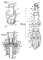
- Fig. 1 eine perspektivische Außenansicht der Rückschlagventilvorrichtung im zusammengefügten Zustand;
- Fig. 2 eine explodierte perspektivische Ansicht der Einzelteile der Rückschlagventilvorrichtung und
- Fig. 3 einen Querschnitt längs der Linie 3-3 in Figur 1.
- Figure 1 is an external perspective view of the check valve device in the assembled state.
- Fig. 2 is an exploded perspective view of the individual parts of the check valve device and
- 3 shows a cross section along the line 3-3 in FIG. 1.
Die normalerweise im Schließzustand befindliche Rückschlagventilvorrichtung weist ein aus zwei Gehäuseteilen 11 und 25 zusammengesetztes Ventilgehäuse 10 auf. Der Gehäuseteil 11 besteht aus einem rohrförmigen Stutzen 12, an dessen eines Ende ein zylindrischer becherförmiger Ansatz 16 angeformt ist, dessen Innen- und Au ßendurchmesser größer als die entsprechenden Durchmesser des Stutzens 12 sind. Am anderen Ende des Stutzens 12 befinden sich nach außen gerichtete radiale Verriegelungsnocken 13. Die Innenfläche und die Außenfläche der Wand 57 des Ansatzes 16 sind kreiszylindrisch, während der kreisförmige Einlaßabschnitt 17 eines Durchlaßkanals 117 in dem Stutzen 12 mit gegen den Ansatz 16 gerichteter Verjüngung konisch verläuft. Auf der Innenfläche der Wand 57 des Ansatzes 16 sind mehrere axiale Rippen angeordnet, die kürzer als die Wand 57 und mit großen gegenseitigen Abständen über ihren Umfang verteilt angeordnet sind. Die Wand 57 des Ansatzes 16 ist über einen radial einwärts gerichteten Übergangsteil 18 an den Stutzen 12 angeschlossen. Die Innenfläche des Übergangsteils 18 verläuft im wesentlichen senkrecht zur Innenfläche der Wand 57 des Ansatzes 16 und bildet eine ebene Schulter 14. In der der inneren Mündung des Einlaßabschnittes 17 zugewandten Kante der Schulter 14 ist eine Umfangsauskehlung 166 ausgebildet, deren Ober- und Unterkante radial zueinander so versetzt sind, daß die Auskehlung gegen den Ansatz 16 vorsprungslos offen ist. In der Mündung des Einlaßabschnittes 17 ist ein Querbalken 15 vorgesehen, dessen Enden an der Innenfläche des Stutzens 12 befestigt sind. Der Querbalken 15 ist an seinem dem Ansatz 16 zugewandten Rand im wesentlichen eben, während sein gegenüberliegender Rand zur Erleichterung der Flüssigkeitsumströmung abgerundet ist. Der ebene Rand des Querbalkens 15 liegt im wesentlichen in der Ebene der Oberkante der Umfangsauskehlung 166.The check valve device, which is normally in the closed state, has a
Der andere Gehäuseteil 25 des Ventilgehäuses 10 besteht aus einem Außenkonus 30 mit einem kreiszylindrischen Auslaßabschnitt 37 des Durchlaßkanals 117, der zu dem Einlaßabschnitt 17 koaxial ausgerichtet ist. Der Außen konus 30 ist mit Abstand von einer konzentrischen Hülse 22 umgeben, auf deren kreiszylindrischer Innenfläche 31 ein Innengewinde 34 mit großer Steigung ausgebildet ist, das der Aufnahme von Verriegelungsnocken eines angesetzten Innenkonus einer zu einem Patienten führenden Leitung dient. Auf der Außenfläche der Hülse 22 sind abwechselnd breite Längsrippen und schmale Längsrillen zur Verbesserung der Griffigkeit beim Zusammenschrauben von Teilen angebracht. An die Hülse 22 und den Außenkonus 30 ist über einen radial nach außen gerichteten Übergangsteil einstückig ein becherförmiger Ansatz 26 angeformt, dessen Wand 28 auf der Innenfläche und auf der Außenfläche kreiszylindrisch gestaltet ist. Der Außendurchmesser des Ansatzes 16 ist geringfügig kleiner als der Innendurchmesser des Ansatzes 26, so daß beide Ansätze passend zusammengesteckt und durch Ultraschallverschweißung fest und dicht miteinander verbunden werden können. Die beiden zusammengesteckten Ansätze 16 und 26 bilden eine Kammer 52 mit kreiszylindrischer Umfangsfläche, einem ebenen Boden 24 und einer zu diesem parallelen durch die Schulter 14 geformten ringartigen Oberwand. Der Durchmesser der Kammer 52 ist größer als derjenige des Durchlaßkanals 117.The
In der Kammer 52 ist eine kreisförmige Ventilscheibe 50 mit parallelen ebenen Oberflächen 51 und 53 angeordnet, die aus flexiblem gummielastischem Material hergestellt und durch Eigenelastizität rückstellfähig ist. Ferner befindet sich in der Kammer 52 ein dreieckiger Plattenkörper 40, dessen Dreieck-Basis mit nach beiden Seiten gerichteten Fortsätzen 42 mit dem Boden 24 der Kammer 52 einstückig ausgebildet ist. Von beiden Flächen des Plattenkörpers 40 gehen sternförmig weitere Stege 142 aus, die ebenfalls mit dem Boden 24 der Kammer 52 einstückig geformt sind. Die Fortsätze 42 und die Stege 142 enden mit Abstand vor der Innenfläche der Wand 57 des Gehäuseteils 11. Auf der leicht abgerundeten Spitze des Plattenkörpers 40 liegt das Zentrum der Ventilscheibe 50. Der untere ebene Rand des Querbalkens 15 drückt den Mittelbereich der Ventilscheibe 50 fest gegen die Spitze des Plattenkörpers 40. Vorzugsweise wird ein derartiger Druck ausgeübt, daß die Dreiecksspitze eine kleine Einbuchtung 140 (Fig.3) in der Ventilscheibe 50 verursacht. Diese Einbuchtung 140 hält die Ventilscheibe 50 anschließend in zentrierter Position und sichert sie gegen seitliche Bewegungen. Sollte dennoch eine Seitenbewegung auftreten oder sich bei der Montage der Rückschlagventilvorrichtung eine geringfügige Verschiebung ergeben, so verhindern die Längsrippen 19 an der Innenfläche der Wand 57 ein Anhaften oder Festklemmen des Umfangsrandes 55 der Ventilscheibe 50 an der Kammerinnenfläche. Die Spitze des Plattenkörpers 40 liegt im wesentlichen in der Ebene der Unterkante der Auskehlung 166 des Gehäuseteiles 11, so daß die Oberseite des Randbereiches der Ventilscheibe 50 in Schließstellung mit gewisser Vorspannung gegen die Unterkante der Auskehlung 166 anliegt, die als Ventilkörpersitz dient.Arranged in the chamber 52 is a
Bei Anschluß des Stutzens 12 an eine Infusionsvorrichtung drückt der Flüssigkeitsstrom in Richtung des Pfeiles B den Randbereich der Ventilscheibe 50 von der Unterkante der Auskehlung 166 gegen die Seiten des Dreiecks des Plattenkörpers 40 weg und ein freier Flüssigkeitsstrom in Richtung der Pfeile A durchströmt den Durchlaßkanal 117 von dem Einlaßabschnitt 17 zu dem Auslaßabschnitt 37. Um jedoch vor Anschluß einer Infusionsvorrichtung, beispielsweise zum Zuspritzen oder zum Abziehen von Flüssigkeiten, die Rückschlagventilvorrich tung öffnen zu können, ist ein Bügel 60 vorgesehen, der als Betätigungsteil für die Ventilscheibe 50 wirksam ist. Der Bügel 60, der vorzugsweise aus Kunststoff gefertigt ist, besteht aus einem kreisförmigen Ring 62, an dessen eine Seite zwei einander diametral gegenüberliegende Schenkel 64 einstückig angeformt sind. Die beiden Schenkel 64 stehen im wesentlichen senkrecht von dem Ring 62 ab, sie sind im Verhältnis zum Umfang des Ringes 64 schmal und weisen an ihrem freien Ende jeweils eine nach außen gerichtete Rippe 66 auf. Der Durchmesser des Ringes 62 entspricht dem Durchmesser des Einlaßabschnittes 17 des Durchlaßkanals 117 an seiner engsten Stelle, d.h. an der Einmündung in die Kammer 52 (Fig. 3). Die Außenfläche des Ringes 62 ist mit der Außenfläche der Schenkel 64 bündig, so daß sich bis auf die Rippen 66 eine glatte vorsprungslose Umfangsfläche des Bügels 60 ergibt. Die Rippen 66 der Schenkel 64 ragen in die Auskehlung 166 hinein und untergreifen in der in Fig. 3 gezeigten Position die Oberkante der Auskehlung 166, so daß der Bügel 60 gegen Herausziehen bzw. Herausfallen aus dem Einlaßabschnitt 17 gesichert ist. In dieser oberen Position des Bügels 16 berührt er die Oberseite der Ventilscheibe 50 nicht und diese verharrt in ihrer Schließstellung.When connecting
Zum Öffnen der Rückschlagventilvorrichtung wird der Kegel einer Spritze an den Ring 62 angesetzt und es wird durch Vorschub des Spritzenkegels der Bügel 60 in Richtung des Pfeiles B verschoben. Diese Verschiebung bewirkt, daß die Enden der Schenkel 64 gegen die Oberseite des elastisch verformbaren Randbereiches der Ventilscheibe 50 drücken und ihn von der Unterkante der Auskehlung 166 wegschieben, so daß der Durchlaß geöffnet wird. Die Position der Schenkelenden und die Ventil scheibenverformung bei maximalem Öffnungszustand ist in Fig. 3 gestrichelt angedeutet. Die Unterfläche der Ventilscheibe 50 liegt in diesem Zustand gegen die beiden Seiten des Dreiecks des Plattenkörpers 40 an. Es kann nun mit Hilfe der Spritze beliebig medikamentöse Flüssigkeit in den Durchlaßkanal 117 eingespritzt oder Körperfluid aus dem Patienten abgezogen werden. Nach Beendigung dieses Vorganges wird die Spritze zurückgezogen und die Rückstellkraft der Ventilscheibe 50 bringt ihren Randbereich in Schließstellung zurück und verschiebt den Bügel 60 in seine obere Grundstellung. Wird nun die Rückschlagventilvorrichtung an eine Infusionsvorrichtung angekoppelt, so kann der Flüssigkeitsstrom ungehindert durch den Bügel 60 die Ventilscheibe zur Öffnung des Durchlasses 117 verformen. Bei rückströmender Flüssigkeit veranlaßt diese gemeinsam mit der Rückstellfähigkeit des Ventilscheibenmaterials ein sofortiges Zurückschnellen der Ventilscheibe 50 in ihre im wesentlichen ebene Grundform mit der Folge eines unverzüglichen Verschlusses des Durchlaßkanals 117 bei Flüssigkeitsrückstrom. Der Bügel 60 hindert auch diesen Vorgang nicht, weil die verdickten Enden seiner Schenkel 64 in der Auskehlung 166 mit Abstand oberhalb der Oberseite der Ventilscheibe 50 versenkt sind.To open the check valve device, the cone of a syringe is placed on the
Bei der Montage der Rückschlagventilvorrichtung wird der Bügel 60 so in den Einlaßabschnitt 17 des Gehäuseteiles 11 eingesetzt, daß seine beiden Schenkel 64 den Querbalken 15 flankieren, ihn jedoch nicht berühren. Da der Querbalken 15 zu der Ebene des Plattenkörpers 40 unter einem Winkel, vorzugsweise einem Winkel von 90°, ausgerichtet ist, liegen die beiden Schenkel 64 mit der Ebene des Plattenkörpers 40 in gemeinsamer Flucht und bei Niederdrücken des Bügels 60 dienen die beiden Seiten des Dreiecks des Plattenkörpers 40 als Anschlag für die Ventilscheibe 50, so daß sie nicht über das durch den spitzen Winkel des Dreiecks des Plattenkörpers 40 definierte Maß hinaus deformiert wird. Auf diese Weise wird die Rückstellfähigkeit der Ventilscheibe 50 über längere Zeit zuverlässig aufrechterhalten.When installing the check valve device, the
Die ineinandersteckenden Ansätze 16 und 26 der beiden Gehäuseteile 11 und 25 werden nach dem Einbau der Teile vorzugsweise durch Ultraschallschweißung fest und unlösbar miteinander verbunden. Die zusammengefügte und verschweißte Vorrichtung läßt sich nur durch Zerstörung des Ventilgehäuses 10 auseinandernehmen. Da die Ventilscheibe 50 zwischen der Spitze des Plattenkörpers 40 und dem ebenen unteren Rand des Querbalkens 15 eingespannt ist, bleibt sie stets zentriert und kann sich nicht in Seitenrichtung bewegen. Hierdurch wird eine sehr wirksame Funktion der Ventilscheibe 50 sowohl beim Öffnen durch Flüssigkeitsstrom oder mit Hilfe des Bügels 60 als auch bei der Rückschlagfunktion bei Flüssigkeitsrückstrom erzielt.The interlocking lugs 16 and 26 of the two
Claims (8)
dadurch gekennzeichnet, daß in dem Einlaßabschnitt (17) des Durchlaßkanals (117) ein axial verschiebbarer Bügel (60) angeordnet ist, dessen Schenkel (64) gegen den Randbereich der Ventilscheibe (50) andrückbar sind.1. Check valve device, consisting of a sleeve-shaped valve housing (10) with an open at both ends passage (117), which has an inlet section (17) and an outlet section (37), between which an enlarged chamber (52) is formed, in which a centrally held valve disk (50) made of elastic material is arranged, the edge area of which rests against a housing shoulder in the closed position,
characterized in that an axially displaceable bracket (60) is arranged in the inlet section (17) of the passage channel (117), the legs (64) of which can be pressed against the edge region of the valve disk (50).
dadurch gekennzeichnet, daß der Einlaßabschnitt (17) des Durchlaßkanals (117) kreisförmigen Querschnitt aufweist und daß der Bügel (60) aus einem kreisförmigen Ring (62) besteht, von dessen einer Seite die axial gerichteten Schenkel (64) ausgehen und an dessen andere Seite der Kegel einer Spritze ansetzbar ist.2. Check valve device according to claim 1,
characterized in that the inlet section (17) of the passage channel (117) has a circular cross-section and that the bracket (60) consists of a circular ring (62), on one side of which the axially directed legs (64) extend and on the other side the cone of a syringe can be attached.
dadurch gekennzeichnet, daß der Ring (62) zwei einander gegenüberliegende Schenkel (64) aufweist, die nach der gleichen Seite senkrecht von dem Ring (62) abstehen.3. Check valve device according to claim 2,
characterized in that the ring (62) has two opposite legs (64) which protrude perpendicularly from the ring (62) on the same side.
dadurch gekennzeichnet, daß die freien Enden der Schenkel (64) nach außen gerichtete vorspringende Rippen (66) aufweisen und daß die vorspringenden Rippen (66) in eine Umfangsauskehlung (166) an der Kante der Gehäuseschulter (14) zwischen der Kammer (52) und dem Einlaßabschnitt (17) des Durchlaßkanals (117) eingreifen.4. Check valve device according to one of claims 1-3,
characterized in that the free ends of the legs (64) have outwardly projecting ribs (66) and in that the projecting ribs (66) fit into a peripheral groove (166) on the edge of the housing shoulder (14) between the chamber (52) and engage the inlet portion (17) of the passageway (117).
dadurch gekennzeichnet, daß das Ventilgehäuse (10) aus einem ersten und einem zweiten Gehäuseteil (11;25) besteht, die jeweils einen zylindrischen becherförmigen Ansatz (16;26) aufweisen; daß der Außendurchmesser des ersten zylindrischen Ansatzes (16) geringfügig kleiner ist als der Innendurchmesser des zweiten zylindrischen Ansatzes (26) und beide Ansätze (16,26) zur Bildung der geschlossenen zylindrischen Kammer (52) zusammengesteckt sind;
daß der erste Gehäuseteil (11) in dem Einlaßabschnitt (17) des Durchlaßkanals (117) am Übergang zu der Kammer (52) mit einem Querbalken (15) versehen ist, der gegen die Ventilscheibe (50) drückt und an beiden Längsrändern mit Abstand von den Schenkeln (64) des Bügels (60) flankiert ist und daß auf dem Boden des becherförmigen Ansatzes (26) des zweiten Gehäuseteiles (25) die Basis eines dreieckigen Plattenkörpers (40) angeordnet ist, dessen Spitze dem Querbalken (15) gegenüberliegt und mit diesem das Zentrum der Ventilscheibe (50) eingeklemmt hält und der im wesentlichen in der Ebene der beiden Schenkel (64) des Bügels (60) ausgerichtet ist.5. Check valve device according to one of claims 1-4,
characterized in that the valve housing (10) consists of a first and a second housing part (11; 25), each having a cylindrical cup-shaped extension (16; 26); that the outer diameter of the first cylindrical projection (16) is slightly smaller than the inner diameter of the second cylindrical projection (26) and the two projections (16, 26) are plugged together to form the closed cylindrical chamber (52);
that the first housing part (11) in the inlet section (17) of the passage (117) at the transition to the chamber (52) is provided with a cross bar (15) which presses against the valve disc (50) and at both longitudinal edges at a distance of the legs (64) of the bracket (60) is flanked and that on the bottom of the cup-shaped extension (26) of the second housing part (25) the base of a triangular plate body (40) is arranged, the tip of which lies opposite the crossbar (15) and with this pinched the center of the valve disc (50) holds and which is aligned substantially in the plane of the two legs (64) of the bracket (60).
dadurch gekennzeichnet, daß die Ventilscheibe (50) mit Ausnahme ihres beim Zusammenfügen der beiden Gehäuseteile (11;25) leicht deformierten zentralen Bereiches auf beiden zueinander parallelen Seiten eben ist.6. Check valve device according to one of claims 1-5,
characterized in that, with the exception of its central region which is slightly deformed when the two housing parts (11; 25) are joined together, the valve disc (50) is flat on both sides parallel to one another.
dadurch gekennzeichnet, daß die ineinandersteckenden Ansätze (16;26) der beiden Gehäuseteile (11;25) miteinander ultraschallverschweißt sind.7. check valve device according to one of claims l - 6,
characterized in that the nested lugs (16; 26) of the two housing parts (11; 25) are ultrasonically welded together.
dadurch gekennzeichnet, daß die beiden Gehäuseteile (11;25) aus glasklarem Kunststoff hergestellt sind und daß der Bügel (60) aus farbigem, undurchsichtigem Kunststoff besteht.8. Check valve device according to one of claims 1-7,
characterized in that the two housing parts (11; 25) are made of clear plastic and that the bracket (60) consists of colored, opaque plastic.
Priority Applications (1)
| Application Number | Priority Date | Filing Date | Title |
|---|---|---|---|
| AT87108969T ATE66727T1 (en) | 1986-09-25 | 1987-06-23 | NON-RETURN VALVE DEVICE. |
Applications Claiming Priority (2)
| Application Number | Priority Date | Filing Date | Title |
|---|---|---|---|
| US06/911,419 US4683916A (en) | 1986-09-25 | 1986-09-25 | Normally closed automatic reflux valve |
| US911419 | 1986-09-25 |
Publications (3)
| Publication Number | Publication Date |
|---|---|
| EP0261317A2 true EP0261317A2 (en) | 1988-03-30 |
| EP0261317A3 EP0261317A3 (en) | 1989-02-01 |
| EP0261317B1 EP0261317B1 (en) | 1991-08-28 |
Family
ID=25430208
Family Applications (1)
| Application Number | Title | Priority Date | Filing Date |
|---|---|---|---|
| EP19870108969 Expired - Lifetime EP0261317B1 (en) | 1986-09-25 | 1987-06-23 | Check valve device |
Country Status (6)
| Country | Link |
|---|---|
| US (1) | US4683916A (en) |
| EP (1) | EP0261317B1 (en) |
| AT (1) | ATE66727T1 (en) |
| DE (2) | DE8708668U1 (en) |
| ES (1) | ES2023853B3 (en) |
| GR (1) | GR3002629T3 (en) |
Cited By (4)
| Publication number | Priority date | Publication date | Assignee | Title |
|---|---|---|---|---|
| EP0472088A1 (en) * | 1990-08-22 | 1992-02-26 | WEX, Roland | Valve assembly for medical fluid circuits |
| DE4442352C1 (en) * | 1994-11-29 | 1995-12-21 | Braun Melsungen Ag | Valve arrangement provided in connector for use e.g. with cannula |
| DE19545452C1 (en) * | 1995-12-06 | 1996-11-14 | Thomas Michael Jokisch | Non return valve for fluids with small pressure differences |
| US8728020B2 (en) | 2007-10-04 | 2014-05-20 | Gambro Lundia Ab | Infusion apparatus |
Families Citing this family (197)
| Publication number | Priority date | Publication date | Assignee | Title |
|---|---|---|---|---|
| US5353837A (en) * | 1986-03-04 | 1994-10-11 | Deka Products Limited Partnership | Quick-disconnect valve |
| US5116021A (en) * | 1986-03-04 | 1992-05-26 | Deka Products Limited Partnership | Quick-disconnect valve |
| US5251873B1 (en) * | 1992-06-04 | 1995-05-02 | Vernay Laboratories | Medical coupling site. |
| US4813941A (en) * | 1987-09-03 | 1989-03-21 | Leslie Shea | Pneumothorax treatment device |
| US4838875A (en) * | 1987-12-09 | 1989-06-13 | Somor Andrew T | Method and apparatus for dealing with intravenous fluids |
| US5964785A (en) | 1988-01-25 | 1999-10-12 | Baxter International Inc. | Bayonet look cannula for pre-slit y-site |
| WO1989006553A2 (en) | 1988-01-25 | 1989-07-27 | Baxter International Inc. | Pre-slit injection site and tapered cannula |
| US5064416A (en) * | 1988-05-26 | 1991-11-12 | Newgard Kent W | Self-occluding intravascular cannula assembly |
| US4874377A (en) * | 1988-05-26 | 1989-10-17 | Davis Newgard Revocable Family Living Trust | Self-occluding intravascular cannula assembly |
| US5098393A (en) * | 1988-05-31 | 1992-03-24 | Kurt Amplatz | Medical introducer and valve assembly |
| CA1330412C (en) | 1988-07-08 | 1994-06-28 | Steven C. Jepson | Pre-slit injection site and tapered cannula |
| US4946455A (en) * | 1988-11-25 | 1990-08-07 | Rosen Robert J | Medical tubing connector |
| MX173202B (en) | 1989-03-17 | 1994-02-08 | Baxter Int | PLACE TO PLACE INJECTIONS WITH PRE-CUT AND SHARP CANNULA |
| US4915351A (en) * | 1989-06-30 | 1990-04-10 | Hoffman Albert R | Hose coupling valve |
| US5465938A (en) * | 1990-05-29 | 1995-11-14 | Werge; Robert W. | Universal fluid flow control |
| WO1995023002A1 (en) * | 1990-05-29 | 1995-08-31 | Paradis Joseph R | Control of fluid flow |
| US5190067A (en) * | 1990-05-29 | 1993-03-02 | Nypro, Inc. | Directional flow control |
| US5201722A (en) * | 1990-09-04 | 1993-04-13 | Moorehead Robert H | Two-way outdwelling slit valving of medical liquid flow through a cannula and methods |
| US5205834A (en) * | 1990-09-04 | 1993-04-27 | Moorehead H Robert | Two-way outdwelling slit valving of medical liquid flow through a cannula and methods |
| US5169393A (en) * | 1990-09-04 | 1992-12-08 | Robert Moorehead | Two-way outdwelling slit valving of medical liquid flow through a cannula and methods |
| US5203775A (en) * | 1990-09-18 | 1993-04-20 | Medex, Inc. | Needleless connector sample site |
| US5776125A (en) | 1991-07-30 | 1998-07-07 | Baxter International Inc. | Needleless vial access device |
| US5360413A (en) * | 1991-12-06 | 1994-11-01 | Filtertek, Inc. | Needleless access device |
| CZ149294A3 (en) | 1991-12-18 | 1994-11-16 | Icu Medical Inc | Medicinal valve |
| US5215538A (en) * | 1992-02-05 | 1993-06-01 | Abbott Laboratories | Connector-activated in-line valve |
| US5464399A (en) * | 1992-02-18 | 1995-11-07 | St. Francis Research Institute | Needleless intravenous infusion system |
| US5624414A (en) * | 1992-02-18 | 1997-04-29 | St. Francis Research Institute | Needleless straight infusion port |
| US5242423A (en) * | 1992-03-09 | 1993-09-07 | American Home Products Corporation | Needleless syringe |
| US5533708A (en) * | 1992-06-04 | 1996-07-09 | Vernay Laboratories, Inc. | Medical coupling site valve body |
| US5501426A (en) * | 1992-06-04 | 1996-03-26 | Vernay Laboratories, Inc. | Medical coupling site valve body |
| US5254086A (en) * | 1992-07-31 | 1993-10-19 | Ballard Medical Products | Medical lavage apparatus and methods |
| FR2696160B1 (en) * | 1992-09-28 | 1994-12-02 | Oreal | Aerosol-type packaging container refillable with compressed gas. |
| US5405333A (en) * | 1992-12-28 | 1995-04-11 | Richmond; Frank M. | Liquid medicament bag with needleless connector fitting using boat assembly |
| US5298024A (en) * | 1992-12-28 | 1994-03-29 | Frank Richmond | Multi-liquid medicament delivery system with reflex valves |
| US5391150A (en) * | 1992-12-28 | 1995-02-21 | Richmond; Frank | IV bag with needleless connector ports |
| US5354272A (en) * | 1993-03-02 | 1994-10-11 | Baxter International Inc. | Improved injectate delivery system |
| US5395348A (en) * | 1993-05-04 | 1995-03-07 | Symbiosis Corporation | Medical intravenous administration line connectors |
| US5848994A (en) * | 1993-07-28 | 1998-12-15 | Richmond; Frank M. | IV sets with needleless spikeless fittings and valves |
| US6206860B1 (en) | 1993-07-28 | 2001-03-27 | Frank M. Richmond | Spikeless connection and drip chamber with valve |
| US5445623A (en) * | 1993-07-28 | 1995-08-29 | Richmond; Frank M. | Drip chamber with luer fitting |
| US5445630A (en) * | 1993-07-28 | 1995-08-29 | Richmond; Frank M. | Spike with luer fitting |
| US5342326A (en) * | 1993-09-22 | 1994-08-30 | B. Braun Medical, Inc. | Capless medical valve |
| US5419776A (en) * | 1993-09-30 | 1995-05-30 | Baer; Robert M. | Pneumothorax treatment device |
| US5849843A (en) * | 1993-11-16 | 1998-12-15 | Baxter International Inc. | Polymeric compositions for medical packaging and devices |
| US5785693A (en) * | 1993-11-26 | 1998-07-28 | Haining; Michael L. | Medical connector |
| US5533983A (en) * | 1993-11-26 | 1996-07-09 | Haining; Michael L. | Valved medical connector |
| WO1995015193A1 (en) * | 1993-11-30 | 1995-06-08 | Medex, Inc. | Anti-reflux valve with environmental barrier |
| US5447286A (en) * | 1994-01-21 | 1995-09-05 | Deka Products Limited Partnership | High flow valve |
| US5603702A (en) * | 1994-08-08 | 1997-02-18 | United States Surgical Corporation | Valve system for cannula assembly |
| US5453097A (en) * | 1994-08-15 | 1995-09-26 | Paradis; Joseph R. | Control of fluid flow |
| US5509912A (en) * | 1994-10-24 | 1996-04-23 | Vlv Associates | Connector |
| US5514116A (en) * | 1994-10-24 | 1996-05-07 | Vlv Associates | Connector |
| US6297046B1 (en) | 1994-10-28 | 2001-10-02 | Baxter International Inc. | Multilayer gas-permeable container for the culture of adherent and non-adherent cells |
| US5935847A (en) * | 1994-10-28 | 1999-08-10 | Baxter International Inc. | Multilayer gas-permeable container for the culture of adherent and non-adherent cells |
| US5618268A (en) * | 1995-06-06 | 1997-04-08 | B. Braun Medical Inc. | Medical infusion devices and medicine delivery systems employing the same |
| US6391404B1 (en) | 1995-06-07 | 2002-05-21 | Baxter International Inc. | Coextruded multilayer film materials and containers made therefrom |
| US6024220A (en) * | 1995-06-07 | 2000-02-15 | Baxter International Inc. | Encapsulated seam for multilayer materials |
| US5738663A (en) | 1995-12-15 | 1998-04-14 | Icu Medical, Inc. | Medical valve with fluid escape space |
| US5954313A (en) * | 1995-12-29 | 1999-09-21 | Rymed Technologies, Inc. | Medical intravenous administration line connectors having a luer activated valve |
| US5788215A (en) | 1995-12-29 | 1998-08-04 | Rymed Technologies | Medical intravenous administration line connectors having a luer or pressure activated valve |
| US5833213A (en) * | 1995-12-29 | 1998-11-10 | Rymed Technologies, Inc. | Multiple dose drug vial adapter for use with a vial having a pierceable septum and a needleless syringe |
| ATE481124T1 (en) | 1996-02-27 | 2010-10-15 | Braun Melsungen Ag | NEEDLE TIP PROTECTION FOR SUBCUTANEOUS INJECTIONS |
| US6629959B2 (en) * | 1996-02-27 | 2003-10-07 | Injectimed, Inc. | Needle tip guard for percutaneous entry needles |
| US5651772A (en) * | 1996-02-28 | 1997-07-29 | Aeroquip Corporation | Needle guard assembly |
| US5817069A (en) * | 1996-02-28 | 1998-10-06 | Vadus, Inc. | Valve assembly |
| US5775671A (en) * | 1996-06-13 | 1998-07-07 | Nypro Inc. | Luer-activated valve |
| DE69713051T2 (en) * | 1996-07-03 | 2003-01-23 | Baxter Int | METHOD FOR WELDING A TUBULAR INSERT IN A CONTAINER |
| US5725503A (en) * | 1996-08-07 | 1998-03-10 | Aeroquip Corporation | Ratcheting needle protector assembly |
| AU3900997A (en) * | 1996-08-07 | 1998-02-25 | Aeroquip Corporation | Needle protector |
| JP3752631B2 (en) * | 1996-11-18 | 2006-03-08 | ナイプロ・インク | Swabable lure cone valve |
| US6883778B1 (en) | 1996-11-18 | 2005-04-26 | Nypro Inc. | Apparatus for reducing fluid drawback through a medical valve |
| US7789864B2 (en) | 1996-11-18 | 2010-09-07 | Nypro Inc. | Luer-activated valve |
| US5842682A (en) * | 1996-11-26 | 1998-12-01 | The Procter & Gamble Company | Non-leaking, non-venting liquid filled canister quick disconnect system |
| US5814024A (en) * | 1996-11-27 | 1998-09-29 | Elcam Plastics | Needleless valve |
| US5807348A (en) * | 1996-11-27 | 1998-09-15 | Elcam Plastics | Needleless valve |
| US6106502A (en) * | 1996-12-18 | 2000-08-22 | Richmond; Frank M. | IV sets with needleless fittings and valves |
| US5954698A (en) * | 1997-01-08 | 1999-09-21 | Vadus, Inc. | Catheter apparatus having valved catheter hub and needle protector |
| US6080137A (en) * | 1997-01-08 | 2000-06-27 | Vadus, Inc. | Needle protector |
| CH692846A5 (en) | 1997-02-24 | 2002-11-29 | Baxter Biotech Tech Sarl | Multilayered co-extruded films for sterilizable containers fluids. |
| BR9804920A (en) | 1997-05-20 | 1999-09-14 | Baxter Inernational Inc | Needle free connector |
| US5957898A (en) | 1997-05-20 | 1999-09-28 | Baxter International Inc. | Needleless connector |
| EP0903179A1 (en) * | 1997-09-18 | 1999-03-24 | Metrohm Ag | Microvalve |
| US5992462A (en) * | 1998-10-28 | 1999-11-30 | Vernay Laboratories, Inc. | Disc type check valve |
| US6027097A (en) * | 1998-12-03 | 2000-02-22 | Lakeshore Automatic Products, Inc. | Water stop hose connector |
| US6267564B1 (en) | 1999-05-12 | 2001-07-31 | Sims Deltec, Inc. | Medical reservoir bag and system |
| US6290690B1 (en) | 1999-06-21 | 2001-09-18 | Alcon Manufacturing, Ltd. | Simultaneous injection and aspiration of viscous fluids in a surgical system |
| US6482188B1 (en) | 1999-10-01 | 2002-11-19 | Mission Medical Devices, Inc. | Nonvented needle-free injection valve |
| US6926696B2 (en) | 1999-12-23 | 2005-08-09 | Owais Mohammed | Hypodermic syringe needle assembly and method of making the same |
| US6540262B1 (en) | 2000-01-10 | 2003-04-01 | James W. Humphreys | Ferrule-free hose fittings |
| DE20002476U1 (en) * | 2000-02-12 | 2000-05-18 | Braun Melsungen Ag | Steam sterilizable liquid valve |
| US6695817B1 (en) | 2000-07-11 | 2004-02-24 | Icu Medical, Inc. | Medical valve with positive flow characteristics |
| WO2002034326A2 (en) | 2000-10-23 | 2002-05-02 | Nypro, Inc. | Anti-drawback medical valve |
| JP2005500142A (en) * | 2001-08-22 | 2005-01-06 | ナイプロ・インク | Medical valve with expansion member |
| US20070161970A1 (en) * | 2004-04-16 | 2007-07-12 | Medrad, Inc. | Fluid Delivery System, Fluid Path Set, and Pressure Isolation Mechanism with Hemodynamic Pressure Dampening Correction |
| US20080154214A1 (en) | 2006-12-22 | 2008-06-26 | Medrad, Inc. | Flow Based Pressure Isolation and Fluid Delivery System Including Flow Based Pressure Isolation |
| US6869426B2 (en) * | 2001-11-13 | 2005-03-22 | Nypro Inc. | Anti-drawback medical valve |
| US7753892B2 (en) | 2001-11-13 | 2010-07-13 | Nypro Inc. | Anti-drawback medical valve |
| US7837658B2 (en) | 2001-11-13 | 2010-11-23 | Nypro Inc. | Anti-drawback medical valve |
| US6908459B2 (en) | 2001-12-07 | 2005-06-21 | Becton, Dickinson And Company | Needleless luer access connector |
| DE20210394U1 (en) | 2002-07-04 | 2002-09-12 | Braun Melsungen Ag | catheter introducer |
| WO2004004807A1 (en) * | 2002-07-09 | 2004-01-15 | Gambro Lundia Ab | An infusion device for medical use. |
| US7025744B2 (en) * | 2002-10-04 | 2006-04-11 | Dsu Medical Corporation | Injection site for male luer or other tubular connector |
| US8377039B2 (en) | 2002-10-04 | 2013-02-19 | Nxstage Medical, Inc. | Injection site for male luer or other tubular connector |
| US7357792B2 (en) * | 2002-10-29 | 2008-04-15 | Nypro Inc. | Positive push medical valve with internal seal |
| US7285110B2 (en) * | 2003-06-10 | 2007-10-23 | P. Rowan Smith, Jr. | Retractable hypodermic safety syringe |
| CA2534390C (en) | 2003-07-09 | 2010-10-05 | Jms Co., Ltd. | Mixture injection port |
| US7914502B2 (en) * | 2003-07-31 | 2011-03-29 | Nypro Inc. | Anti-drawback medical valve |
| US7343943B2 (en) * | 2004-05-13 | 2008-03-18 | Forhealth Technologies, Inc. | Medication dose underfill detection system and application in an automated syringe preparing system |
| US7163035B2 (en) * | 2004-05-13 | 2007-01-16 | Forhealth Technologies, Inc. | Automated use of a vision system to detect foreign matter in reconstituted drugs before transfer to a syringe |
| US7128105B2 (en) * | 2004-04-07 | 2006-10-31 | Forhealth Technologies, Inc. | Device for reconstituting a drug vial and transferring the contents to a syringe in an automated matter |
| US7017623B2 (en) * | 2004-06-21 | 2006-03-28 | Forhealth Technologies, Inc. | Automated use of a vision system to unroll a label to capture and process drug identifying indicia present on the label |
| US7291134B2 (en) * | 2004-10-25 | 2007-11-06 | P. Rowan Smith, Jr. | Medical connector |
| ATE542564T1 (en) | 2004-11-05 | 2012-02-15 | Icu Medical Inc | MEDICAL CONNECTOR WITH HIGH FLOW CHARACTERISTICS |
| US7976518B2 (en) | 2005-01-13 | 2011-07-12 | Corpak Medsystems, Inc. | Tubing assembly and signal generator placement control device and method for use with catheter guidance systems |
| US7887519B2 (en) | 2005-01-14 | 2011-02-15 | Nypro Inc. | Valve with internal lifter |
| US7499581B2 (en) * | 2005-02-10 | 2009-03-03 | Forhealth Technologies, Inc. | Vision system to calculate a fluid volume in a container |
| US7314462B2 (en) * | 2005-04-12 | 2008-01-01 | Span-America Medical Systems, Inc. | Passive needle-stick protector |
| US7503908B2 (en) * | 2005-07-22 | 2009-03-17 | B. Braun Medical Inc. | Needleless access port valves |
| WO2007047795A2 (en) * | 2005-10-20 | 2007-04-26 | Richmond Frank M | Connector/device with reflux valves |
| US7302960B2 (en) * | 2005-10-26 | 2007-12-04 | Smiths Medical Asd, Inc. | Momentary high pressure valve |
| US8002755B2 (en) | 2006-04-11 | 2011-08-23 | Nypro Inc. | Anti-drawback medical valve and method |
| EP2049194A1 (en) | 2006-08-11 | 2009-04-22 | Nypro Inc. | Medical valve with expandable member |
| US7814731B2 (en) | 2006-10-20 | 2010-10-19 | Forhealth Technologies, Inc. | Automated drug preparation apparatus including a bluetooth communications network |
| US7900658B2 (en) | 2006-10-20 | 2011-03-08 | Fht, Inc. | Automated drug preparation apparatus including drug vial handling, venting, cannula positioning functionality |
| WO2008052140A2 (en) | 2006-10-25 | 2008-05-02 | Icu Medical, Inc. | Medical connector |
| ES2375210T3 (en) | 2006-10-30 | 2012-02-27 | Gambro Lundia Ab | AIR SEPARATOR FOR EXTRACORPOSE FLUID TREATMENT SETS. |
| US20080172006A1 (en) * | 2007-01-15 | 2008-07-17 | Medrad, Inc. | Patency Check Compatible Check Valve And Fluid Delivery System Including The Patency Check Compatible Check Valve |
| US8256464B2 (en) * | 2007-05-22 | 2012-09-04 | Rjc Products Llc | Check valve flap for fluid injector |
| US8752579B2 (en) * | 2007-05-22 | 2014-06-17 | Rjc Products Llc | Check valve for fluid injector |
| US8051856B2 (en) | 2007-07-30 | 2011-11-08 | Passy-Muir, Inc. | Tracheostomy valves and related methods |
| USD747463S1 (en) | 2007-07-30 | 2016-01-12 | Passy-Muir, Inc. | Tracheostomy valve |
| US7992588B2 (en) * | 2008-01-21 | 2011-08-09 | Rong-Jyh Song | Open state maintainable valve device for an inflatable article |
| US8065924B2 (en) * | 2008-05-23 | 2011-11-29 | Hospira, Inc. | Cassette for differential pressure based medication delivery flow sensor assembly for medication delivery monitoring and method of making the same |
| US8511638B2 (en) * | 2008-09-05 | 2013-08-20 | Carefusion 303, Inc. | Neonatal Luer-activated medical connector |
| US8074964B2 (en) * | 2008-09-05 | 2011-12-13 | Carefusion 303, Inc. | Luer activated medical connector having a low priming volume |
| JP5273473B2 (en) * | 2008-09-12 | 2013-08-28 | 株式会社ジェイ・エム・エス | Spout and liquid container with spout |
| WO2010044353A1 (en) * | 2008-10-16 | 2010-04-22 | 株式会社ジェイ・エム・エス | Spout and liquid containing body with spout |
| US20100112696A1 (en) * | 2008-11-03 | 2010-05-06 | Baxter International Inc. | Apparatus And Methods For Processing Tissue To Release Cells |
| US8309343B2 (en) * | 2008-12-01 | 2012-11-13 | Baxter International Inc. | Apparatus and method for processing biological material |
| US8523826B2 (en) * | 2009-02-13 | 2013-09-03 | Cytyc Corporation | Luer-type needle-free valve fitting with bypass |
| US8403822B2 (en) * | 2009-02-20 | 2013-03-26 | Cytyc Corporation | Passive vent for brachytherapy balloon catheters |
| US8454579B2 (en) | 2009-03-25 | 2013-06-04 | Icu Medical, Inc. | Medical connector with automatic valves and volume regulator |
| US8568371B2 (en) | 2009-06-22 | 2013-10-29 | Np Medical Inc. | Medical valve with improved back-pressure sealing |
| EP3760180A3 (en) | 2009-07-29 | 2021-01-20 | ICU Medical, Inc. | Fluid transfer devices and methods of use |
| CN102686254B (en) * | 2009-11-09 | 2014-08-06 | 株式会社根本杏林堂 | One-way valve with opening function, tube unit provided with the one-way valve, and drug solution injection system |
| US9056163B2 (en) * | 2010-02-24 | 2015-06-16 | Becton, Dickinson And Company | Safety drug delivery system |
| US9205248B2 (en) | 2010-02-24 | 2015-12-08 | Becton, Dickinson And Company | Safety Drug delivery connectors |
| USD644731S1 (en) | 2010-03-23 | 2011-09-06 | Icu Medical, Inc. | Medical connector |
| GB201007226D0 (en) * | 2010-04-30 | 2010-06-16 | Reckitt & Colman Overseas | A combination of a liquid container and a reill device |
| US8758306B2 (en) | 2010-05-17 | 2014-06-24 | Icu Medical, Inc. | Medical connectors and methods of use |
| US9138572B2 (en) | 2010-06-24 | 2015-09-22 | Np Medical Inc. | Medical valve with fluid volume alteration |
| US9545495B2 (en) | 2010-06-25 | 2017-01-17 | Smiths Medical Asd, Inc. | Catheter assembly with seal member |
| US8652104B2 (en) | 2010-06-25 | 2014-02-18 | Smiths Medical Asd, Inc. | Catheter assembly with seal member |
| US8465461B2 (en) | 2010-07-27 | 2013-06-18 | Becton, Dickinson And Company | Blunt needle safety drug delivery system |
| US8353869B2 (en) | 2010-11-02 | 2013-01-15 | Baxa Corporation | Anti-tampering apparatus and method for drug delivery devices |
| WO2013036772A1 (en) | 2011-09-08 | 2013-03-14 | Corpak Medsystems, Inc. | Apparatus and method used with guidance system for feeding and suctioning |
| US9155863B2 (en) * | 2011-10-06 | 2015-10-13 | Becton, Dickinson And Company | Multiple use stretching and non-penetrating blood control valves |
| CA3075368C (en) | 2011-12-22 | 2023-07-11 | Icu Medical, Inc. | Fluid transfer devices and methods of use |
| US8973596B2 (en) | 2012-07-12 | 2015-03-10 | Confluent Surgical, Inc. | Applicator assembly with integral check-valve |
| DE102012109192A1 (en) | 2012-09-27 | 2014-03-27 | B. Braun Avitum Ag | fluid port |
| DE102013100479A1 (en) * | 2013-01-17 | 2014-07-17 | B. Braun Avitum Ag | Medical fluid bag |
| US9381320B2 (en) | 2013-03-18 | 2016-07-05 | Becton, Dickinson And Company | Multiple-use intravenous catheter assembly septum and septum actuator |
| EP3505801B1 (en) | 2013-10-08 | 2020-06-17 | Dayco IP Holdings, LLC | Noise attenuation in a check valve unit or apparatus for producing vacuum |
| US20150133861A1 (en) | 2013-11-11 | 2015-05-14 | Kevin P. McLennan | Thermal management system and method for medical devices |
| WO2015077184A1 (en) | 2013-11-25 | 2015-05-28 | Icu Medical, Inc. | Methods and system for filling iv bags with therapeutic fluid |
| ES2941891T3 (en) | 2013-12-11 | 2023-05-26 | Icu Medical Inc | Retention valve |
| EP2883566B1 (en) | 2013-12-11 | 2017-05-24 | Gambro Lundia AB | Extracorporeal blood treatment system and valve unit for pre/post infusion |
| US10052474B2 (en) * | 2014-03-18 | 2018-08-21 | I-V Access Technoiogy, Inc. | Intravenous catheter with pressure activated valve |
| KR102213985B1 (en) | 2014-04-04 | 2021-02-08 | 데이코 아이피 홀딩스 엘엘시 | A bypass check valve and venturi devices having the same |
| US10107240B2 (en) | 2014-04-04 | 2018-10-23 | Dayco Ip Holdings, Llc | Check valves and Venturi devices having the same |
| CN105378240B (en) | 2014-06-06 | 2018-10-09 | 戴科知识产权控股有限责任公司 | Noise attentuation in Venturi and/or check-valves |
| JP6756699B2 (en) | 2014-07-10 | 2020-09-16 | デイコ アイピー ホールディングス,エルエルシーDayco Ip Holdings,Llc | Dual venturi device |
| US10143795B2 (en) | 2014-08-18 | 2018-12-04 | Icu Medical, Inc. | Intravenous pole integrated power, control, and communication system and method for an infusion pump |
| EP3822135A1 (en) | 2014-08-27 | 2021-05-19 | Dayco IP Holdings, LLC | Low-cost evacuator for an engine having tuned venturi gaps |
| US10364914B2 (en) * | 2014-09-29 | 2019-07-30 | B. Braun Medical Inc. | Valve device, a delivery system including same and method |
| USD786427S1 (en) | 2014-12-03 | 2017-05-09 | Icu Medical, Inc. | Fluid manifold |
| USD793551S1 (en) | 2014-12-03 | 2017-08-01 | Icu Medical, Inc. | Fluid manifold |
| EP3242997B1 (en) | 2015-01-09 | 2019-09-25 | Dayco IP Holdings, LLC | Crankcase ventilating evacuator |
| US10151283B2 (en) | 2015-02-25 | 2018-12-11 | Dayco Ip Holdings, Llc | Evacuator with motive fin |
| US10316864B2 (en) | 2015-04-13 | 2019-06-11 | Dayco Ip Holdings, Llc | Devices for producing vacuum using the venturi effect |
| AU2016267763B2 (en) | 2015-05-26 | 2021-07-08 | Icu Medical, Inc. | Disposable infusion fluid delivery device for programmable large volume drug delivery |
| JP6655162B2 (en) | 2015-07-17 | 2020-02-26 | デイコ アイピー ホールディングス, エルエルシーDayco Ip Holdings, Llc | Device for generating a vacuum utilizing the Venturi effect, having a plurality of sub-passages and a drive outlet in a drive section |
| PT3552652T (en) | 2015-08-18 | 2021-07-16 | Braun Melsungen Ag | Catheter devices with valves |
| US10190455B2 (en) | 2015-10-28 | 2019-01-29 | Dayco Ip Holdings, Llc | Venturi devices resistant to ice formation for producing vacuum from crankcase gases |
| AU2016365335B2 (en) | 2015-12-04 | 2021-10-21 | Icu Medical, Inc. | Systems methods and components for transferring medical fluids |
| US10940096B2 (en) * | 2016-04-05 | 2021-03-09 | Medela Holding Ag | Enteral feeding air purge system and method |
| USD851745S1 (en) | 2016-07-19 | 2019-06-18 | Icu Medical, Inc. | Medical fluid transfer system |
| EP3487468A4 (en) | 2016-07-25 | 2020-03-25 | ICU Medical, Inc. | Systems, methods, and components for trapping air bubbles in medical fluid transfer modules and systems |
| WO2018218132A1 (en) | 2017-05-26 | 2018-11-29 | Bayer Healthcare Llc | Injector state logic with hemodynamic monitoring |
| US10415227B2 (en) * | 2017-05-26 | 2019-09-17 | Ips Corporation | Drain valve assembly |
| US10406326B2 (en) | 2017-08-31 | 2019-09-10 | I-V Access Technology, Inc. | Methods and devices for vascular access |
| US11291802B2 (en) * | 2017-10-09 | 2022-04-05 | Becton, Dickinson And Company | Fluid storage unit, systems, and methods for catheter priming |
| US11850377B2 (en) | 2018-12-17 | 2023-12-26 | B. Braun Melsungen Ag | Catheter assemblies and related methods |
| USD939079S1 (en) | 2019-08-22 | 2021-12-21 | Icu Medical, Inc. | Infusion pump |
| US11590057B2 (en) | 2020-04-03 | 2023-02-28 | Icu Medical, Inc. | Systems, methods, and components for transferring medical fluids |
| RU207895U1 (en) * | 2021-03-03 | 2021-11-23 | Федеральное государственное унитарное предприятие «Всероссийский научно-исследовательский институт автоматики им.Н.Л.Духова» (ФГУП «ВНИИА») | Check valve |
| US11607525B1 (en) * | 2022-06-30 | 2023-03-21 | I-V Access Technology, Inc. | Methods and devices for vascular access |
Citations (5)
| Publication number | Priority date | Publication date | Assignee | Title |
|---|---|---|---|---|
| US3570484A (en) * | 1967-08-31 | 1971-03-16 | Eschmann Bros & Walsh Ltd | Intravenous valve assembly |
| US4143853A (en) * | 1977-07-14 | 1979-03-13 | Metatech Corporation | Valve for use with a catheter or the like |
| DE3100442C1 (en) * | 1962-05-08 | 1982-09-30 | Dr. Eduard Fresenius, Chemisch-pharmazeutische Industrie KG, 6380 Bad Homburg | Adapter piece for plastic cannulas and vein catheters |
| US4387879A (en) * | 1978-04-19 | 1983-06-14 | Eduard Fresenius Chemisch Pharmazeutische Industrie Kg | Self-sealing connector for use with plastic cannulas and vessel catheters |
| US4535820A (en) * | 1984-05-24 | 1985-08-20 | Burron Medical Inc. | Normally closed check valve |
Family Cites Families (1)
| Publication number | Priority date | Publication date | Assignee | Title |
|---|---|---|---|---|
| US2299643A (en) * | 1940-07-03 | 1942-10-20 | Frederick K Moody | Valved connector |
-
1986
- 1986-09-25 US US06/911,419 patent/US4683916A/en not_active Expired - Lifetime
-
1987
- 1987-06-23 AT AT87108969T patent/ATE66727T1/en not_active IP Right Cessation
- 1987-06-23 DE DE19878708668 patent/DE8708668U1/de not_active Expired
- 1987-06-23 DE DE8787108969T patent/DE3772499D1/en not_active Expired - Lifetime
- 1987-06-23 EP EP19870108969 patent/EP0261317B1/en not_active Expired - Lifetime
- 1987-06-23 ES ES87108969T patent/ES2023853B3/en not_active Expired - Lifetime
-
1991
- 1991-08-29 GR GR91401208T patent/GR3002629T3/en unknown
Patent Citations (5)
| Publication number | Priority date | Publication date | Assignee | Title |
|---|---|---|---|---|
| DE3100442C1 (en) * | 1962-05-08 | 1982-09-30 | Dr. Eduard Fresenius, Chemisch-pharmazeutische Industrie KG, 6380 Bad Homburg | Adapter piece for plastic cannulas and vein catheters |
| US3570484A (en) * | 1967-08-31 | 1971-03-16 | Eschmann Bros & Walsh Ltd | Intravenous valve assembly |
| US4143853A (en) * | 1977-07-14 | 1979-03-13 | Metatech Corporation | Valve for use with a catheter or the like |
| US4387879A (en) * | 1978-04-19 | 1983-06-14 | Eduard Fresenius Chemisch Pharmazeutische Industrie Kg | Self-sealing connector for use with plastic cannulas and vessel catheters |
| US4535820A (en) * | 1984-05-24 | 1985-08-20 | Burron Medical Inc. | Normally closed check valve |
Cited By (6)
| Publication number | Priority date | Publication date | Assignee | Title |
|---|---|---|---|---|
| EP0472088A1 (en) * | 1990-08-22 | 1992-02-26 | WEX, Roland | Valve assembly for medical fluid circuits |
| DE4442352C1 (en) * | 1994-11-29 | 1995-12-21 | Braun Melsungen Ag | Valve arrangement provided in connector for use e.g. with cannula |
| EP0714675A2 (en) | 1994-11-29 | 1996-06-05 | B. Braun Melsungen Ag | Valve device |
| US5613663A (en) * | 1994-11-29 | 1997-03-25 | B. Braun Melsungen Ag | Valve device |
| DE19545452C1 (en) * | 1995-12-06 | 1996-11-14 | Thomas Michael Jokisch | Non return valve for fluids with small pressure differences |
| US8728020B2 (en) | 2007-10-04 | 2014-05-20 | Gambro Lundia Ab | Infusion apparatus |
Also Published As
| Publication number | Publication date |
|---|---|
| GR3002629T3 (en) | 1993-01-25 |
| DE3772499D1 (en) | 1991-10-02 |
| EP0261317B1 (en) | 1991-08-28 |
| US4683916A (en) | 1987-08-04 |
| DE8708668U1 (en) | 1987-08-06 |
| ATE66727T1 (en) | 1991-09-15 |
| ES2023853B3 (en) | 1992-02-16 |
| EP0261317A3 (en) | 1989-02-01 |
Similar Documents
| Publication | Publication Date | Title |
|---|---|---|
| EP0261317B1 (en) | Check valve device | |
| EP0307743B1 (en) | Locking valve for a device to drain or infuse liquids | |
| EP0412968B1 (en) | Syringe, in particular for medical use | |
| EP0882466B1 (en) | Device for the dosed application of a liquid drug | |
| EP2094342B1 (en) | Catheter apparatus with infusion port and valves | |
| DE60023511T2 (en) | PISTON FOR SYRINGE | |
| WO2004004819A1 (en) | Catheter insertion device | |
| EP0714675A2 (en) | Valve device | |
| EP0511538A2 (en) | Valve device for a catheter | |
| DE3010782A1 (en) | DISPENSING DEVICE FOR ADHESIVE OR THE LIKE | |
| DE3103031C2 (en) | Device for withdrawing body fluids | |
| DE102012222062B3 (en) | diaphragm valve | |
| DE2040072B2 (en) | Injection syringe | |
| EP0641228B1 (en) | Single use injection device | |
| DE2654655A1 (en) | INFUSION DEVICE | |
| EP0638328A1 (en) | Checkvalve | |
| EP0160807A2 (en) | Catheter rinsing device | |
| EP0191945B1 (en) | Blood-sampling device | |
| DE4433198C1 (en) | Applicator | |
| EP0312073B1 (en) | Connector with a valve | |
| CH456050A (en) | Infusion set that can be connected to an infusion bottle | |
| EP2712653B1 (en) | Fluid coupling | |
| DE19906603A1 (en) | Automatic safety infusion catheter needle for intravenous injections | |
| EP3375481B1 (en) | Connecting element | |
| DE19909654C2 (en) | Valve arrangement for flow control of medical fluids |
Legal Events
| Date | Code | Title | Description |
|---|---|---|---|
| PUAI | Public reference made under article 153(3) epc to a published international application that has entered the european phase |
Free format text: ORIGINAL CODE: 0009012 |
|
| AK | Designated contracting states |
Kind code of ref document: A2 Designated state(s): AT BE CH DE ES FR GB GR IT LI NL SE |
|
| PUAL | Search report despatched |
Free format text: ORIGINAL CODE: 0009013 |
|
| AK | Designated contracting states |
Kind code of ref document: A3 Designated state(s): AT BE CH DE ES FR GB GR IT LI NL SE |
|
| RHK1 | Main classification (correction) |
Ipc: F16K 15/18 |
|
| 17P | Request for examination filed |
Effective date: 19890718 |
|
| 17Q | First examination report despatched |
Effective date: 19900511 |
|
| GRAA | (expected) grant |
Free format text: ORIGINAL CODE: 0009210 |
|
| AK | Designated contracting states |
Kind code of ref document: B1 Designated state(s): AT BE CH DE ES FR GB GR IT LI NL SE |
|
| REF | Corresponds to: |
Ref document number: 66727 Country of ref document: AT Date of ref document: 19910915 Kind code of ref document: T |
|
| ITF | It: translation for a ep patent filed |
Owner name: ING. C. GREGORJ S.P.A. |
|
| REF | Corresponds to: |
Ref document number: 3772499 Country of ref document: DE Date of ref document: 19911002 |
|
| ET | Fr: translation filed | ||
| GBT | Gb: translation of ep patent filed (gb section 77(6)(a)/1977) | ||
| REG | Reference to a national code |
Ref country code: ES Ref legal event code: FG2A Ref document number: 2023853 Country of ref document: ES Kind code of ref document: B3 |
|
| PLBE | No opposition filed within time limit |
Free format text: ORIGINAL CODE: 0009261 |
|
| STAA | Information on the status of an ep patent application or granted ep patent |
Free format text: STATUS: NO OPPOSITION FILED WITHIN TIME LIMIT |
|
| 26N | No opposition filed | ||
| REG | Reference to a national code |
Ref country code: GR Ref legal event code: FG4A Free format text: 3002629 |
|
| EAL | Se: european patent in force in sweden |
Ref document number: 87108969.4 |
|
| PGFP | Annual fee paid to national office [announced via postgrant information from national office to epo] |
Ref country code: GR Payment date: 19960628 Year of fee payment: 10 |
|
| PG25 | Lapsed in a contracting state [announced via postgrant information from national office to epo] |
Ref country code: GR Free format text: LAPSE BECAUSE OF NON-PAYMENT OF DUE FEES Effective date: 19970630 |
|
| PGFP | Annual fee paid to national office [announced via postgrant information from national office to epo] |
Ref country code: FR Payment date: 19980518 Year of fee payment: 12 |
|
| PGFP | Annual fee paid to national office [announced via postgrant information from national office to epo] |
Ref country code: GB Payment date: 19980527 Year of fee payment: 12 |
|
| PGFP | Annual fee paid to national office [announced via postgrant information from national office to epo] |
Ref country code: BE Payment date: 19980623 Year of fee payment: 12 |
|
| PGFP | Annual fee paid to national office [announced via postgrant information from national office to epo] |
Ref country code: NL Payment date: 19980625 Year of fee payment: 12 |
|
| PG25 | Lapsed in a contracting state [announced via postgrant information from national office to epo] |
Ref country code: GB Free format text: LAPSE BECAUSE OF NON-PAYMENT OF DUE FEES Effective date: 19990623 |
|
| PG25 | Lapsed in a contracting state [announced via postgrant information from national office to epo] |
Ref country code: FR Free format text: THE PATENT HAS BEEN ANNULLED BY A DECISION OF A NATIONAL AUTHORITY Effective date: 19990630 Ref country code: BE Free format text: LAPSE BECAUSE OF NON-PAYMENT OF DUE FEES Effective date: 19990630 |
|
| BERE | Be: lapsed |
Owner name: B. BRAUN MELSUNGEN A.G. Effective date: 19990630 |
|
| PG25 | Lapsed in a contracting state [announced via postgrant information from national office to epo] |
Ref country code: NL Free format text: LAPSE BECAUSE OF NON-PAYMENT OF DUE FEES Effective date: 20000101 |
|
| GBPC | Gb: european patent ceased through non-payment of renewal fee |
Effective date: 19990623 |
|
| NLV4 | Nl: lapsed or anulled due to non-payment of the annual fee |
Effective date: 20000101 |
|
| REG | Reference to a national code |
Ref country code: FR Ref legal event code: ST |
|
| PGFP | Annual fee paid to national office [announced via postgrant information from national office to epo] |
Ref country code: AT Payment date: 20040611 Year of fee payment: 18 |
|
| PGFP | Annual fee paid to national office [announced via postgrant information from national office to epo] |
Ref country code: ES Payment date: 20040622 Year of fee payment: 18 |
|
| PGFP | Annual fee paid to national office [announced via postgrant information from national office to epo] |
Ref country code: SE Payment date: 20040623 Year of fee payment: 18 Ref country code: CH Payment date: 20040623 Year of fee payment: 18 |
|
| PG25 | Lapsed in a contracting state [announced via postgrant information from national office to epo] |
Ref country code: IT Free format text: LAPSE BECAUSE OF NON-PAYMENT OF DUE FEES;WARNING: LAPSES OF ITALIAN PATENTS WITH EFFECTIVE DATE BEFORE 2007 MAY HAVE OCCURRED AT ANY TIME BEFORE 2007. THE CORRECT EFFECTIVE DATE MAY BE DIFFERENT FROM THE ONE RECORDED. Effective date: 20050623 Ref country code: AT Free format text: LAPSE BECAUSE OF NON-PAYMENT OF DUE FEES Effective date: 20050623 |
|
| PG25 | Lapsed in a contracting state [announced via postgrant information from national office to epo] |
Ref country code: SE Free format text: LAPSE BECAUSE OF NON-PAYMENT OF DUE FEES Effective date: 20050624 Ref country code: ES Free format text: LAPSE BECAUSE OF NON-PAYMENT OF DUE FEES Effective date: 20050624 |
|
| PG25 | Lapsed in a contracting state [announced via postgrant information from national office to epo] |
Ref country code: LI Free format text: LAPSE BECAUSE OF NON-PAYMENT OF DUE FEES Effective date: 20050630 Ref country code: CH Free format text: LAPSE BECAUSE OF NON-PAYMENT OF DUE FEES Effective date: 20050630 |
|
| REG | Reference to a national code |
Ref country code: CH Ref legal event code: PL |
|
| EUG | Se: european patent has lapsed | ||
| PGFP | Annual fee paid to national office [announced via postgrant information from national office to epo] |
Ref country code: DE Payment date: 20060731 Year of fee payment: 20 |
|
| REG | Reference to a national code |
Ref country code: ES Ref legal event code: FD2A Effective date: 20050624 |