EP0261649B2 - Nebulizer - Google Patents
Nebulizer Download PDFInfo
- Publication number
- EP0261649B2 EP0261649B2 EP87113857A EP87113857A EP0261649B2 EP 0261649 B2 EP0261649 B2 EP 0261649B2 EP 87113857 A EP87113857 A EP 87113857A EP 87113857 A EP87113857 A EP 87113857A EP 0261649 B2 EP0261649 B2 EP 0261649B2
- Authority
- EP
- European Patent Office
- Prior art keywords
- liquid
- baffle
- nebulizer
- air introduction
- compressed air
- Prior art date
- Legal status (The legal status is an assumption and is not a legal conclusion. Google has not performed a legal analysis and makes no representation as to the accuracy of the status listed.)
- Expired - Lifetime
Links
Images


Classifications
-
- A—HUMAN NECESSITIES
- A61—MEDICAL OR VETERINARY SCIENCE; HYGIENE
- A61M—DEVICES FOR INTRODUCING MEDIA INTO, OR ONTO, THE BODY; DEVICES FOR TRANSDUCING BODY MEDIA OR FOR TAKING MEDIA FROM THE BODY; DEVICES FOR PRODUCING OR ENDING SLEEP OR STUPOR
- A61M11/00—Sprayers or atomisers specially adapted for therapeutic purposes
- A61M11/06—Sprayers or atomisers specially adapted for therapeutic purposes of the injector type
-
- A—HUMAN NECESSITIES
- A61—MEDICAL OR VETERINARY SCIENCE; HYGIENE
- A61M—DEVICES FOR INTRODUCING MEDIA INTO, OR ONTO, THE BODY; DEVICES FOR TRANSDUCING BODY MEDIA OR FOR TAKING MEDIA FROM THE BODY; DEVICES FOR PRODUCING OR ENDING SLEEP OR STUPOR
- A61M11/00—Sprayers or atomisers specially adapted for therapeutic purposes
- A61M11/001—Particle size control
- A61M11/002—Particle size control by flow deviation causing inertial separation of transported particles
-
- A—HUMAN NECESSITIES
- A61—MEDICAL OR VETERINARY SCIENCE; HYGIENE
- A61M—DEVICES FOR INTRODUCING MEDIA INTO, OR ONTO, THE BODY; DEVICES FOR TRANSDUCING BODY MEDIA OR FOR TAKING MEDIA FROM THE BODY; DEVICES FOR PRODUCING OR ENDING SLEEP OR STUPOR
- A61M16/00—Devices for influencing the respiratory system of patients by gas treatment, e.g. mouth-to-mouth respiration; Tracheal tubes
- A61M16/10—Preparation of respiratory gases or vapours
- A61M16/12—Preparation of respiratory gases or vapours by mixing different gases
- A61M16/122—Preparation of respiratory gases or vapours by mixing different gases with dilution
- A61M16/125—Diluting primary gas with ambient air
-
- A—HUMAN NECESSITIES
- A61—MEDICAL OR VETERINARY SCIENCE; HYGIENE
- A61M—DEVICES FOR INTRODUCING MEDIA INTO, OR ONTO, THE BODY; DEVICES FOR TRANSDUCING BODY MEDIA OR FOR TAKING MEDIA FROM THE BODY; DEVICES FOR PRODUCING OR ENDING SLEEP OR STUPOR
- A61M2209/00—Ancillary equipment
- A61M2209/08—Supports for equipment
- A61M2209/082—Mounting brackets, arm supports for equipment
-
- B—PERFORMING OPERATIONS; TRANSPORTING
- B05—SPRAYING OR ATOMISING IN GENERAL; APPLYING FLUENT MATERIALS TO SURFACES, IN GENERAL
- B05B—SPRAYING APPARATUS; ATOMISING APPARATUS; NOZZLES
- B05B7/00—Spraying apparatus for discharge of liquids or other fluent materials from two or more sources, e.g. of liquid and air, of powder and gas
- B05B7/0012—Apparatus for achieving spraying before discharge from the apparatus
-
- B—PERFORMING OPERATIONS; TRANSPORTING
- B05—SPRAYING OR ATOMISING IN GENERAL; APPLYING FLUENT MATERIALS TO SURFACES, IN GENERAL
- B05B—SPRAYING APPARATUS; ATOMISING APPARATUS; NOZZLES
- B05B7/00—Spraying apparatus for discharge of liquids or other fluent materials from two or more sources, e.g. of liquid and air, of powder and gas
- B05B7/24—Spraying apparatus for discharge of liquids or other fluent materials from two or more sources, e.g. of liquid and air, of powder and gas with means, e.g. a container, for supplying liquid or other fluent material to a discharge device
- B05B7/2402—Apparatus to be carried on or by a person, e.g. by hand; Apparatus comprising containers fixed to the discharge device
- B05B7/2405—Apparatus to be carried on or by a person, e.g. by hand; Apparatus comprising containers fixed to the discharge device using an atomising fluid as carrying fluid for feeding, e.g. by suction or pressure, a carried liquid from the container to the nozzle
- B05B7/2429—Apparatus to be carried on or by a person, e.g. by hand; Apparatus comprising containers fixed to the discharge device using an atomising fluid as carrying fluid for feeding, e.g. by suction or pressure, a carried liquid from the container to the nozzle the carried liquid and the main stream of atomising fluid being brought together after discharge
-
- B—PERFORMING OPERATIONS; TRANSPORTING
- B05—SPRAYING OR ATOMISING IN GENERAL; APPLYING FLUENT MATERIALS TO SURFACES, IN GENERAL
- B05B—SPRAYING APPARATUS; ATOMISING APPARATUS; NOZZLES
- B05B7/00—Spraying apparatus for discharge of liquids or other fluent materials from two or more sources, e.g. of liquid and air, of powder and gas
- B05B7/24—Spraying apparatus for discharge of liquids or other fluent materials from two or more sources, e.g. of liquid and air, of powder and gas with means, e.g. a container, for supplying liquid or other fluent material to a discharge device
- B05B7/2402—Apparatus to be carried on or by a person, e.g. by hand; Apparatus comprising containers fixed to the discharge device
- B05B7/2405—Apparatus to be carried on or by a person, e.g. by hand; Apparatus comprising containers fixed to the discharge device using an atomising fluid as carrying fluid for feeding, e.g. by suction or pressure, a carried liquid from the container to the nozzle
- B05B7/2435—Apparatus to be carried on or by a person, e.g. by hand; Apparatus comprising containers fixed to the discharge device using an atomising fluid as carrying fluid for feeding, e.g. by suction or pressure, a carried liquid from the container to the nozzle the carried liquid and the main stream of atomising fluid being brought together by parallel conduits placed one inside the other
Definitions
- the present invention relates to a nebulizer for atomizing a liquid, for instance, for nebulizining a medical liquid against a throat.
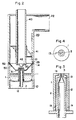
- FIGs. 1a to 1c are cross-sectional views showing the essential portion of the prior-art nebulizers.
- the construction of the nebulizer shown in Fig. 1a is such that a compressed air introduction pipe 101 is provided so as to pass through a side wall of a housing 100, and an end of a suction pipe 104 whose base end is put in a liquid reservoir 103 is positioned near a nozzle 102 formed at an end of the compressed air introduction pipe 101.
- the construction of the nebulizer shown in Fig. 1b is such that a baffle 106 is disposed near both ends of the nozzle 102 and the liquid suction pipe 104.
- a single or plural small-diameter liquid suction passages (pipes) 108 are formed at the outer circumference of a compressed air introduction pipe 107 integral therewith.
- a pressure pump connected to the compressed air introduction pipe is driven to obtain a jet stream through the nozzle, in every nebulizer.
- a vacuum generated near the nozzle sucks a liquid in the liquid suction pipe (or passages) toward the nozzle on the basis of vacuum eject action.
- the liquid sucked upward is mixed with the jet stream, collides against the baffle, and is atomized before discharged outside through an atomized liquid discharge part of the housing.
- a nebulizer according to the preamble of claim 1 is known from BE-A-692 821.
- the baffle is in the shape of a truncated cone.
- a nebulizer having a baffle formed by the spherically shaped end portion of a cylindrical rod. This spherically shaped end portion is located in a frustoconical recess forming a widening opening of the spray nozzle.
- DE-A-3429411 discloses a nebulizer having a wedge shaped baffle provided on the lower side of an arm extending between support poles.
- DE-A-3238149 discloses a nebulizer having a baffle with a flat surface facing the spray nozzle, similar to BE-A-692821.
- An object of the present invention is to provide a nebulizer of higher atomization efficiency by allowing scattered atomized liquid to smoothly move toward an atomized liquid discharge port, after liquid-gas mixture collides against the baffle into atomized liquid.
- the invention is as claimed in claim 1.
- the nebulizer comprises a cylindrical lower housing (bottle 10) formed with a liquid reservoir space 11 at the lower portion thereof and a cylindrical upper housing 20 formed with an atomization space 21 at the lower portion thereof and with an atomized liquid discharge space 22 at the upper portion thereof.
- These two upper and lower housings 20 and 10 are removably fitted to each other via two fitting portions 23 and 14 formed at the lower and upper ends thereof, respectively.
- a cylindrical compressed air introduction pipe 12 is disposed integral with the lower housing 10 so as to pass through the center of the bottom wall in the axial direction thereof.
- This compressed air introduction pipe 12 is formed with a nozzle 13 at its top end thereof, and the lower end of the pipe 12 projecting from the bottom wall of the liquid reservoir space 11 is connected to a pressure pump (not shown) via a tube.
- an external air introduction pipe 40 is formed integral with the upper housing 20 so as to pass through the center of the housing 20.
- This external air introduction pipe 40 is disposed in such a way that the upper end of the pipe 40 projects outward from a bent upper end wall of the upper housing 20 and the lower end thereof is located in the vicinity of the end portion (nozzle 13) of the compressed air introduction pipe 12.
- a baffle 30 is attached to the lower end of this external air introduction pipe 40 via radial (e.g. cross-shaped) ribs 42.
- the baffle 30 of this embodiment is cylindrical in shape and chamfered at the circumference of the end thereof.
- the feature of this embodiment of the nebulizer is to removably and fittably provide the liquid suction pipe 1 to the compressed air introduction pipe 12.
- the liquid suction pipe 1 is formed with an inner diameter larger than an outer diameter of the compressed air introduction pipe 12, with an open lower end surface, and with a flange 1a extending inward and having an aperture (hole 3) at the center thereof at the upper end surface of the pipe 1. Further, there are formed a plurality of liquid charge holes 1b at the lower end of the liquid suction pipe 1.
- this liquid suction pipe 1 Under the condition that this liquid suction pipe 1 is fitted to the compressed air introduction pipe 12, an annular (in cross section) gap is formed between the inner circumferential surface of the liquid suction pipe 1 and the outer circumferential surface of the introduction pipe 12 so as to serve as a liquid suction passage 2.
- This liquid suction passage 2 extends to the upper portion of the liquid suction pipe 1, surrounding the nozzle 13, and reaches the hole 3.
- the hole 3 and the end of the nozzle 13 are located so as to confront the baffle 30 at a predetermined distances.
- a dish-shaped fixing member 50 is provided at the outer circumference of this liquid suction pipe 1 integral with the pipe 1.
- An outer circumferential flange 52 of the fixing member 50 is supported between the fitting portions 23 and 14 of the upper and lower housings 20 and 10.
- the inside end of the fixing member 50 is formed into radial ribs 51 with spaces between rib members.
- liquid charge port 1b at the lower end of the liquid suction pipe 1
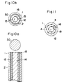
- Fig. 5a is a cross-sectional view showing the essential portion of another modification of fitting condition between the compressed air introduction pipe 12 arid the liquid suction pipe 1, and Fig. 5b is the plan view thereof.
- the liquid suction pipe 1 is formed into a cylinder having upper and lower openings, and the compressed air introduction pipe 12 is provided with no stepped portion at the nozzle portion.
- an annular liquid suction passage is formed.
- a spherical baffle 30 is incorporated.
- Fig. 6 shows a modification of the liquid suction passage.
- the inner diameter of the liquid suction pipe 1 is nearly equal to the outer diameter of the compressed air introduction pipe 12, and four grooves 4 are formed at the inner circumferential surface of the liquid suction pipe 1. Therefore, when the liquid suction pipe 1 is fitted to the compressed air introduction pipe 12, these grooves 4 arranged in circular shape serve as the liquid suction passage.
- Fig. 7 is a cross-sectional view showing still another modification of the fitting condition between the compressed air introduction pipe 12 and the liquid suction pipe 1.
- the compressed air introduction pipe 12 is formed with a tapered end; in the same way, the liquid suction pipe 1 is also formed with a tapered end. That is, the liquid suction passage is narrowed in the upward direction.
- Fig. 8a is a cross-sectional view showing further modification of the fitting condition between the compressed air introduction pipe 12 and the liquid suction pipe 1
- Fig. 8b is its plan view.
- a rod 16 is disposed at the center of the compressed air introduction pipe 12 to which the liquid suction pipe 1 is fitted, and an annular space between the outer periphery of the rod 16 and the compressed air introduction pipe 12 is used as a compressed air passage 17. Therefore, in this example, the compressed air passage 17 and the liquid suction passage 2 are both annular in shape.
- the upper end of the compressed air introduction pipe 12 functions as a nozzle.
- Fig. 9 is a plan view showing still another modification of the liquid suction pipe 1.
- the liquid suction pipe 1 is formed with a plurality (e.g. 4) of grooves 4 at the inner circumferential surface thereof.
- the grooves 4 between the compressed air introduction pipe 12 and the liquid suction pipe 1 become the liquid suction passage. Therefore, in this example, the liquid suction passage is not annular in shape but arranged intermittently in a circular.
- Fig. 10a is a cross-sectional view showing still further modification of the fitting condition between the compressed air introduction pipe 12 and the liquid suction pipe 1
- Fig. 10b is its plan view.
- the compressed air introduction pipe 12 is formed with 4 grooves 15 extending in the axial direction thereof and along the inner circumferential surface thereof.
- a rod 16 having an outer diameter equal to an inner diameter of the compressed air introduction pipe 12 is fitted to the pipe 12, and a gap formed between the rod 16 and the compressed air introduction pipe 12, that is, the grooves 15 function as a compressed air passage. Therefore, in this example, the compressed air passage is arranged intermittently in a circle.
- a liquid suction passage 2 formed between the liquid suction pipe 1 and the compressed air introduction pipe 12 is annular in shape.
- Fig. 11 is a plan view showing further modification of the liquid suction pipe 1.
- a number of grooves 4 are formed in the inner circumferential surface of the liquid suction pipe 1, and a gap between the pipe 1 and the outer circumferential surface of the compressed air introduction pipe 12 is the liquid suction passage when the pipe 1 is fitted to the pipe 12. Therefore, in this example, the plural compressed air passages and the plural liquid suction passages are both arranged intermittently in concentric positional relationship in plural circles.
- liquid and air stream are jetted and collide against the baffle separately, being different from the prior-art nebulizer in which liquid sucked by a vacuum is immediately mixed with the jet stream and collides against the baffle, so that the atomization efficiency is high, and very small noise is produced (in the prior art, relatively large noise is produced when a mixture of liquid and air stream collides against the baffle), thus enhancing the convenience in use.
- the liquid suction passage is large in volume and in diameter. Therefore, oven if liquid crystals or dust included in the liquid reservoir comes into the liquid suction passage, the passage may not be clogged. In case the liquid suction passage is clogged by large-diameter dirt particles such as dust, it is possible to easily clean the passage into no clogging condition by simply removing the liquid suction pipe from the compressed air introduction pipe.
- the nebulizer is easy to manufacture and handle without trouble, thus providing a high atomization efficiency and low-costly nebulizer.
- the baffle is spherical or cylindrical in shape and the diameter thereof is determined larger than that of the jet stream spouting outlet (the opening end of the nozzle 13 and the opening end 3 of the liquid passage 2) of the liquid-gas mixture (jet stream and liquid). Therefore, the gas mixed with liquid collides against the baffle sphere 30 and in scattered toward the radial direction. However, part of the atomized liquid scattered radially is obstructed by the surface of the large-diameter baffle sphere 30 and therefore drops toward the liquid reservoir 11 (downward) without flowing toward the atomized liquid discharge port 22 (upward), thus lowering the atomization efficiency.
- the nebulizer is constructed by removably fitting the upper housing 20 and the lower housing 10.
- An O-ring 25 is disposed between the two fitting portions 23 and 14. Further, a mouth piece 24 is replaceably provided for the upper housing 20.
- the upper end of the external air introduction pipe 40 is removably fitted to a mounting cylinder 43 formed integral with the housing 20, and the lower end of the pipe 40 is supported on a baffle support cylinder 31.
- the mounting cylinder 43 opens to a part of the housing 20 (an opening 43a). This opening 43a is adjustably opened or closed by an external air introducing open/close shutter 44 slidably disposed on the housing 20.
- the compressed air introduction pipe 12 formed integral with the lower housing 10 at the bottom of the housing 10 and the liquid suction pipe 1 fitted to the pipe 12 are both formed in taper shape at the upper portion thereof in the same way as shown in Fig. 7.
- some ribs 18 e.g. 4 ribs spaced at 90 degrees
- some ribs 18 extending axially at the middle of the height of the pipe 12 are formed integral with the pipe 12 to support the fitted liquid suction pipe 1 and form a gap serving as a liquid suction passage 2 between the two.
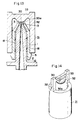
- the feature of this embodiment is to form the baffle 30 into a special shape to increase discharge efficiency of the liquid-gas mixture (atomized liquid) colliding against the baffle.
- the baffle 30 is formed integral with the cylinder 31 under the middle of an arm portion 33 extending between two support poles 32 projecting upward from the upper end surface of the support cylinder 31. That is, the baffle 30 is provided so as to project downward from the middle lower surface of the arm 33, This baffle 30 is formed into a narrow-width rectangular parallelepiped in shape and formed with a projection having a curved surface 30a at the lower portion thereof.
- the shape of this baffle 30 is the same as that formed by vertically cutting a spherical baffle (sphere) at two positions in parallel to the longitudinal central line so as to have a predetermined width.
- the width and length of the baffle 30 are determined so as to correspond to a diameter of the jet stream spouting outlet (the end of the nozzle 13 and the opening 3 of the liquid suction passage) of the liquid-gas mixture. Further, the curved portion 30a extends in the longitudinal and width directions.
- the support cylinder 31 formed with such baffle 30 is removably fitted to the liquid suction pipe 1, and the lower end of the support cylinder 31 are supported by the flange 5 of the liquid suction pipe 1. Under these fitted conditions, the baffle 30 is located a little over the top end of the nozzle 13 of the compressed air introduction pipe 12 and the opening 3 of the liquid suction passage 2.
- nebulizer In the nebulizer thus constructed, compressed air is jetted through the nozzle 13 in the form of jet stream, and a vacuum generated near the opening 3 of the liquid suction passage 2 due to this jet stream moves liquid upward in the liquid suction passage 2 on the basis of vacuum eject action, and jets the liquid from the passage opening 3. Further, the jetted liquid and stream collide against the baffle 30 positioned over the nozzle 13 and opening 3 into atomization.
- the liquid-gas mixture collides against the central portion of the curved surface 30a of the baffle 30 positioned at right angles with respect to the jet direction .
- the width of the baffle 30 is narrow, the atomized liquid scattered in the radial directions rises upward without being subjected to any obstruction.
- the collision surface is curved, the atomized liquid can smoothly move upward along the curved surface 30a. Therefore, almost all the atomized liquid flows upward (toward the atomised liquid discharge port 22) without dropping downward (toward the liquid reservoir space 11), thus improving the discharge rate of the atomized liquid.
- the nebulizer within the housing provided with the liquid reservoir space at the lower portion thereof and the atomizing space and atomised liquid discharge port both communicating with the liquid reservoir space at the upper portion thereof, there are disposed the compressed air introduction pipe having a nozzle at an end thereof, the liquid suction pipe for supplying liquid in the liquid reservoir, and the baffle positioned so as to face the nozzle of the compressed air introduction pipe and the passage opening of the liquid suction pipe, and the baffle is formed in such a way that the lower projecting surface of the narrow rectangular parallelepiped is curved.
- the baffle is rectangular in shape and curved at the lower portion; that is, baffle is formed small in shape as compared with the jet stream spouting outlet of the liquid-gas mixture (the nozzle opening end and liquid suction passage opening). Therefore, liquid-gas mixture jetted from the nozzle end of the compressed air introduction pipe and the liquid suction passage opening of the liquid suction pipe both collide against the curved surface positioned perpendicular to the jet stream direction and scattered. In this moment, since the width of the baffle is narrow, the atomized liquid colliding against the curved surface can smoothly move upward along the curved surface without being subjected to any obstruction, thus improving the atomization efficiency.
- the amount of air introduced inside is adjusted by adjustably opening/closing the external air charge opening 43a of the external air introduction pipe 40, 43, so that the amount of atomized liquid discharged from the discharge port can be adjusted by substantially changing the power (flow rate) of the atomized liquid.
- Fig. 15 shows this embodiment, in which the same parts or elements explained in the first and second embodiments are denoted by the same reference numerals without repeating the description thereof.
- the compressed air introduction pipe 12 and the liquid suction pipe 1 are similar to these shown in Figs. 5a and 5b.
- ribs 18 extending in the axial direction of the pipe 12 and arranged at regular angular intervals are disposed so as to form a gap of the liquid suction passage 2 between the introduction pipe 12 and the suction pipe 1.
- the liquid suction pipe 1 is supported on the bottom surface of the liquid reservoir space 11, and formed with some liquid inlets 1b at the lower portion thereof.
- the lower end of the compressed air introduction pipe 12 is connected to a pressure pump (not shown) via a hose 19 so that compressed air is supplied from the pressure pump.
- a support member 46 is provided at the upper end of the external air introduction pipe 40 disposed on the upper housing 20.
- the pipe 40 is formed with a horizontally directing external air inlet 40a at the position under the support member 46 and outside the housing 20. Further, the support member 46 is formed with a threaded hole 46a.
- a rod 34 is fitted to the external air introduction pipe 40. The upper portion of this rod 34 is threaded at 34a and screwed into the threaded hole 46a in the support member 46 so as to be supported by the support member 46.
- the lower end of the rod 34 is the baffle 30 the same in shape as in Fig 2, and this baffle 30 projects from the lowermost end of the external air introduction pipe 40.
- a knob 35 is attached to the upper end of the rod 34. Therefore, when this knob 35 is rotated to rotate the rod 34, the lower end of the baffle 30 moves up and down.
- the rod 34 is supported at the middle and lower positions via two bearings 45.
- Each bearing 45 is composed of a ring rotatably and slidably fitted to the rod 34 and a radial rib for fixing this ring to the external air introduction pipe 40.
- the compressed air when compressed air is fed to the compressed air introduction pipe 12 via the hose 19, the compressed air is jetted from the nozzle 13 into a jet stream.
- a vacuum generated by this jet stream raises liquid within the liquid suction pipe 1 (whose level is the same as that of the liquid reservoir space 11) on the basis of vacuum eject action and ejects the liquid upward together with the jet stream.
- the jet stream mixed with medical liquid collides against baffle 30 disposed on the lower end of the rod 34 and over the nozzle 13. Therefore, the medical liquid is scattered into atomization condition in various directions.
- the atomized liquid since external air is introduced through the external air introduction pipe 40, the atomized liquid is urged upward by the external air pressure within the atomization space 21 surrounding the external air introduction pipe 40, being discharged to the outside through the atomized stream discharge port 22.
- the baffle 30 disposed at the end of the rod 34 is moved upward or downward, so that a gap between the baffle 30 and the nozzle 13 changes and therefore the amount of atomized liquid can be adjusted.
- Fig. 16 shows a modification. This nebulizer is basically the same as that shown in Fig. 15, the same reference numerals being retained for the same or similar parts which have the same functions.
- a cylindrical support member 47 is vertically disposed downward from the top surface of the upper housing 20; the external air introduction pipe 40 is fittably screwed to this cylindrical support member 47; the baffle 30 is disposed at the lower end of the external air introduction pipe 40; when the external air introduction pipe 40 is moved up and down, the baffle 30 is also moved up and down to adjust a distance between the nozzle 13 and the baffle 30.
- An operation knob 48 is attached to the upper end of the external air introduction pipe 40 for providing an easy adjustment.
- nebulizer The operation of the nebulizer is the same as that shown in Fig. 15.
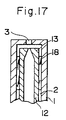
- Fig. 17 shows a modification of the jet stream generating section.
- a small air supply opening 3 is formed at the center of the upper surface of the liquid suction pipe 1, and the nozzle 13 is positioned under this opening 3.
- the amount of atomized liquid is adjustable according to the distance between the nozzle through which compressed air is jetted and the baffle confronting the nozzle.
- a baffle position adjusting means formed with a baffle at one end thereof and retained by the housing at the other end portion thereof is provided so that the distance between the baffle and the nozzle can be adjusted.
- the amount of atomized liquid to be formed is directly controlled (without adjusting the amount of atomized liquid to be discharged from the atomizing space to the outside), it is possible to reduce the amount of atomized liquid to be stored inside, thus improving the liquid atomization efficiency.
- an air compressor of bell-diaphragm type has been used for the pressure pump for generating conpressed air to be supplied to the compressed air introduction pipe 12, that is, for the compressor.
- the nozzle diameter and the opening diameter of the liquid suction passage have been determined on the basis of diaphragm-type compressor characteristics, respectively.
- the pressure when liquid is atomized is universally determined in combination of the atomizing part and the compressor, and the amount of atomized liquid is determined according to the pressure.
- Fig. 18 shows tile mutual relationship between the conventionally adopted diaphragm type air compressor pressure and the amount of atomized liquid (atomizer characteristics).
- the pressure of the diaphragm type air compressor is about 0.75 kg/cm2
- the flow rate at this moment is about 5.0 l/min
- the atomized liquid rate corresponding thereto is about 0.2 ml/min.
- the atomized liquid rate is required to increase (e.g. to 0.4 ml/min)
- the diaphragm type air compressor provided with these performances is of large-sized pump such that the weight is 4 kg or more and the electric power consumption is 50 W or more. Therefore, the size is large; the electric power consumption is high; and the cost is high.
- the noise is as high as 60 dB or more, so that there exists a disadvantages such that if is difficult to install the noisy compressor at a hospital, for instance.
- temperature increases 40 degrees or more in this compressor the compressor is subjected to trouble.
- the life can be known after the compressor will not move, due to the structural standpoint. Therefore, the maintenance chance is lost, and therefore the nebulizer often stops during operation.
- a further embodiment provides a nebulizer having a high atomization efficiency by use of a small-sized light-weight compressor.
- the nebulizer of this further embodiment is constructed as follows: the nebulizer comprises a nebulizer case provided with a compressor inside and an atomizing cylinder removably connected to the compressor in the nebulizer case via an air feeding tube; the compressor is of linear motor driven free piston type; and the atomizing nozzle diameter of the atomizing cylinder is determined so as to correspond to compressor characteristics.
- a linear motor driven free piston type air compressor is used, and the atomizing nozzle diameter is determined on the basis of the compressor characteristics.
- Fig. 19 shows the characteristics of the linear motor driven free piston type air compressor, which indicates that when an atomized liquid rate (4.0 ml/min) twice larger than that of the conventional valve (2.0 ml/min) is required, a compressor whose pressure is about 0.9 kg/cm2 (the flow rate is about 4.0 l/min) is used (see arrows b).
- the linear motor driven free piston type air compressor with the performance as described above is very small in size, vibration, noise and power consumption, but very high is atomization efficiency.
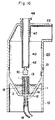
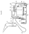
- Fig. 20 is a front view, partially cross-section, showing this further embodiment of the nebulizer.
- the nebulizer comprises a nebulizer case 62 provided with a compressor 61 and a filter housing 71 inside the case and an atomizing cylinder 9 connected to the compressor 61 via an air feeding tube 63.
- the compressor (linear motor driven free piston air compressor) 61 described later is mounted on a rubber mounting base 72 at the middle of a box-shaped inner space of the case 62.
- Some damping members 73 for protecting the compressor 61 from external vibrations or shocks are projectingly provided at both ends and on both side surfacs of the case 62.
- a plurality of ventilation openings 74 are formed on both side walls of the case 62 to radiate heat therethrough.
- an atomizing cylinder housing space 75 there are provided an atomizing cylinder support arm 76 for supporting the atomizing cylinder 9 when the cylinder 9 is used and arm setting portion 77 for receiving the support arm 76 when the cylinder 9 is not used.
- a discharge tube 78 is connected to the air feed section of the compressor 61.
- a pipe joint of this discharge tube 78 is fixed to the outside of the case 62 to removably connect the air feed tube 63 connected to the atomizer cylinder 9.
- a suction tube 79 is connected to the suction section of the compressor 61, and one end of this suction tube 79 is connected to a suction cylinder 71a of the filter housing 71.
- the atomizing cylinder 9 is shown in Fig. 12, in which the compressed air introduction pipe 12 is connected to the air feed tube 63.
- the jet stream spouting part and the baffle of the atomizing cylinder 9 are the same as that shown in Fig. 13, its enlarged view being also shown in Fig. 22.
- a distance between the nozzle 13 and the baffle 30 (the curved surface 30a) is determined to be 0.1 to 0.4 mm; a diameter of the nozzle 13 (jet stream generating aperture diameter) is determined to be 0.4 to 0.6 mm; the outer diameter of the nozzle is determined to be 2 to 3 mm; the curvature of the curved surface 30a of the baffle 30 is determined to be 6 to 10 mm in diameter, in order to improve the atomization efficiency.
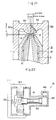
- Fig. 22 is a cross-sectional view diagrammatically slowing the structure of a linear motor driven free piston type air compressor 61.
- a piston 82 is disposed within a cylinder 81; and a spring 83 is attached to one end of the piston 82 to always urge the piston 82 toward the side of the suction opening 85.
- an electromagnetic coil 84 is disposed on the base end side (spring disposed side) of the piston 82.
- a linear motor driven free piston type air compressor 61 is used, and the diameter of the atomizer nozzle 13 is determined so as to correspond to the characteristics of compressor 61, as already explained. Therefore, as shown by the atomizer characteristics in Fig. 20, in order to obtain an atomized liquid rate of 0.4 ml/min, for instance, a compressor whose pressure is about 0.9, kg/cm2 (the atomizer flow rate is about 4.0 l/min) is used.
- the linear motor driven free piston type air compressor 61 of this performance is small in size, light (about 2 kg) in weight, low (20 W) in power consumption, low (about 30 degrees) in temperature rise, little in vibration, and low (40 dB) in noise; as a result, it is possible to drive the compressor quietly. Since the linear motor driven free piston type compressor is used and the atomizer nozzle is determined so as to correspond to the compressor characteristics, it is possible to minimize the compressor while doubling the atomized liquid rate as compared with the conventional type.
- compressed air is fed from the compressor to the nozzle by means of the linear motor driven free piston type air compressor and the nozzle whose diameter is determined according to the compressor characteristics, it is possible to minimize the size and weight of the nebulizer and to improve the atomizer efficiency.
- the nebulizer Since noise, vibration, heat generation, etc. are all minimized, the nebulizer is usable at hospital and home under quiet condition. Further, since the compressor performance is degraded little by little gradually with increasing lapse of time, it is possible to determine the maintenance time when the nebulizer does not operate satisfactorily. Therefore, it is possible to solve the disadvantages involved in the prior art nebulizer such that nebulizer operation stops suddenly during use.
Description
- The present invention relates to a nebulizer for atomizing a liquid, for instance, for nebulizining a medical liquid against a throat.
- Conventionally, there are various nebulizers of different types. Figs. 1a to 1c are cross-sectional views showing the essential portion of the prior-art nebulizers.
- The construction of the nebulizer shown in Fig. 1a is such that a compressed
air introduction pipe 101 is provided so as to pass through a side wall of ahousing 100, and an end of asuction pipe 104 whose base end is put in aliquid reservoir 103 is positioned near anozzle 102 formed at an end of the compressedair introduction pipe 101. Further, although being the same as in Fig. 1a, the construction of the nebulizer shown in Fig. 1b is such that abaffle 106 is disposed near both ends of thenozzle 102 and theliquid suction pipe 104. Further, in the nebulizer shown in Fig. 1c, a single or plural small-diameter liquid suction passages (pipes) 108 are formed at the outer circumference of a compressedair introduction pipe 107 integral therewith. - In use, a pressure pump connected to the compressed air introduction pipe is driven to obtain a jet stream through the nozzle, in every nebulizer. In this operation, a vacuum generated near the nozzle sucks a liquid in the liquid suction pipe (or passages) toward the nozzle on the basis of vacuum eject action. The liquid sucked upward is mixed with the jet stream, collides against the baffle, and is atomized before discharged outside through an atomized liquid discharge part of the housing.
- In the prior-art nebulizers as described above, since the liquid suction pipe or passages are small in diameter, there exist drawbacks in that the liquid suction pipe is subjected to clogging due to crystals of medical liquid or coarse dirt particles.
- In addition, in the prior-art nebulizers, since the liquid suction pipe is formed integral with the housing or the liquid suction passage is formed integral with the compressed air introduction pipe, it is very difficult to clean the clogged liquid suction pipe or passages, thus obstructing a safe nebulization. Further, in the case of a nebulizer in which the liquid suction passages are formed integral with the compressed air introduction piped there exist other problems such that the forming process is complicated, thus resulting in higher manufacturing cost and complicated repair work in case of nebulizer trouble.
- A nebulizer according to the preamble of
claim 1 is known from BE-A-692 821. According to this known nebulizer, the baffle is in the shape of a truncated cone. - From US-A-3762409 there is known a nebulizer having a baffle formed by the spherically shaped end portion of a cylindrical rod. This spherically shaped end portion is located in a frustoconical recess forming a widening opening of the spray nozzle.
- DE-A-3429411 discloses a nebulizer having a wedge shaped baffle provided on the lower side of an arm extending between support poles.
- DE-A-3238149 discloses a nebulizer having a baffle with a flat surface facing the spray nozzle, similar to BE-A-692821.
- An object of the present invention is to provide a nebulizer of higher atomization efficiency by allowing scattered atomized liquid to smoothly move toward an atomized liquid discharge port, after liquid-gas mixture collides against the baffle into atomized liquid.
- The invention is as claimed in
claim 1. - The present invention will be more clearly appreciated from the following description with reference to the attached drawings of which the Figs. 1a to 11 do not show embodiments of the invention.
- Figs. 1a, 1b and 1c are cross-sectional views showing the essential portions of prior-art nebulizers;
- Fig. 2 is a longitudinal cross-sectional view showing the structure of an embodiment of a nebulizer;
- Fig. 3 is an enlarged cross-sectional view showing a jet stream forming section of this embodiment, which illustrates a fitting condition between a compressed air introduction pipe and a liquid suction pipe;
- Fig. 4 is an enlarged plan view showing the same jet stream forming section;
- Fig. 5a is an enlarged cross-sectional view showing the essential portion of modification of the fitting condition between the compressed air introduction pipe and the liquid suction pipe,
- Fig. 5b is a plan view showing the same modification;
- Fig. 6 is a plan view showing another modification of the liquid suction pipe;
- Fig. 7 is an enlarged cross-sectional view showing the essential portion of further modification of the fitting condition between the compressed air introduction pipe and the liquid suction pipe;
- Fig. 8a is an enlarged cross-sectional view showing the essential portion of still further modification of the fitting condition between the compressed air introduction pipe and the liquid suction pipe, Fig. 8b is a plan view showing the same modification;
- Fig. 9 is a plan view showing still another modification of the liquid suction pipe;
- Fig. 10a is an enlarged cross-sectional view showing the essential portion of other modification of the fitting condition between the compressed air introduction pipe and the liquid suction pipe. Fig. 10b is a plan view of the same modification;
- Fig. 11 is a plan view showing other modification of the liquid suction pipe;
- Fig. 12 is a longitudinal cross-sectional view showing the construction of an embodiment of the nebulizer of the present invention;
- Fig. 13 is an enlarged cross-sectional view showing a part provided with a baffle of this embodiment;
- Fig. 14 is a perspective view of the same part;
- Fig. 15 is a longitudinal cross-sectional view showing in an aspect the nebulizer of the present invention;
- Fig. 16 is a longitudinal cross-sectional view showing a modification thereof;
- Fig. 17 is a cross-sectional view showing another modification of the et stream forming section;
- Fig. 18 is a graphical representation showing atomisation characteristics of a prior-art diaphragm type compressor;
- Fig. 19 is a graphical representation showing atomisation characteristics of a free-piston type air compressor driven by a linear motor;
- Fig. 20 is a front cross-sectional view showing a part of cross section of a further embodiment of the nebulizer of the present invention;
- Fig. 21 is an enlarged cross-sectional view showing the relationship between the nozzle and the baffle; and
- Fig. 22 is an outline of the cross-sectional view showing the construction of the free-piston type air compressor driven by a linear motor.
- Figs. 2 to 4 show the basic structure of the nebulizer in question. With reference to these drawings, the nebulizer comprises a cylindrical lower housing (bottle 10) formed with a liquid reservoir space 11 at the lower portion thereof and a cylindrical
upper housing 20 formed with anatomization space 21 at the lower portion thereof and with an atomizedliquid discharge space 22 at the upper portion thereof. These two upper andlower housings fitting portions - At the bottom wall of the
lower housing 10, that is, at the bottom wall of the liquid reservoir space 11, a cylindrical compressedair introduction pipe 12 is disposed integral with thelower housing 10 so as to pass through the center of the bottom wall in the axial direction thereof. This compressedair introduction pipe 12 is formed with anozzle 13 at its top end thereof, and the lower end of thepipe 12 projecting from the bottom wall of the liquid reservoir space 11 is connected to a pressure pump (not shown) via a tube. - Further, an external
air introduction pipe 40 is formed integral with theupper housing 20 so as to pass through the center of thehousing 20. This externalair introduction pipe 40 is disposed in such a way that the upper end of thepipe 40 projects outward from a bent upper end wall of theupper housing 20 and the lower end thereof is located in the vicinity of the end portion (nozzle 13) of the compressedair introduction pipe 12. Abaffle 30 is attached to the lower end of this externalair introduction pipe 40 via radial (e.g. cross-shaped)ribs 42. Thebaffle 30 of this embodiment is cylindrical in shape and chamfered at the circumference of the end thereof. -
Further spiral blades 41 are provided for the lower circumferential surface of the externalair introduction pipe 40. When atomized liquid collides against thisblade 41, large-diameter atomized liquid particles stick upon theblades 41 and only small-diameter atomised liquid particles are fed to the atomizedliquid discharge port 22. - The feature of this embodiment of the nebulizer is to removably and fittably provide the
liquid suction pipe 1 to the compressedair introduction pipe 12. - The
liquid suction pipe 1 is formed with an inner diameter larger than an outer diameter of the compressedair introduction pipe 12, with an open lower end surface, and with a flange 1a extending inward and having an aperture (hole 3) at the center thereof at the upper end surface of thepipe 1. Further, there are formed a plurality of liquid charge holes 1b at the lower end of theliquid suction pipe 1. - Under the condition that this
liquid suction pipe 1 is fitted to the compressedair introduction pipe 12, an annular (in cross section) gap is formed between the inner circumferential surface of theliquid suction pipe 1 and the outer circumferential surface of theintroduction pipe 12 so as to serve as aliquid suction passage 2. Thisliquid suction passage 2 extends to the upper portion of theliquid suction pipe 1, surrounding thenozzle 13, and reaches thehole 3. Thehole 3 and the end of thenozzle 13 are located so as to confront thebaffle 30 at a predetermined distances. - Further, a dish-shaped fixing
member 50 is provided at the outer circumference of thisliquid suction pipe 1 integral with thepipe 1. An outercircumferential flange 52 of the fixingmember 50 is supported between thefitting portions lower housings member 50 is formed into radial ribs 51 with spaces between rib members. - Without forming the liquid charge port 1b at the lower end of the
liquid suction pipe 1, it is also possible to form a gap between the lower end of theliquid suction pipe 1 and the bottom surface of the liquid reservoir space 11 when thesuction pipe 1 is supported by the fixingmember 50 so that liquid in the reservoir space 11 can flow into theliquid suction passage 2 through this gap. - Fig. 5a is a cross-sectional view showing the essential portion of another modification of fitting condition between the compressed
air introduction pipe 12 arid theliquid suction pipe 1, and Fig. 5b is the plan view thereof. - In this modification, the
liquid suction pipe 1 is formed into a cylinder having upper and lower openings, and the compressedair introduction pipe 12 is provided with no stepped portion at the nozzle portion. In this modification as in the first embodiment, an annular liquid suction passage is formed. Further, aspherical baffle 30 is incorporated. - Fig. 6 shows a modification of the liquid suction passage. In this example, the inner diameter of the
liquid suction pipe 1 is nearly equal to the outer diameter of the compressedair introduction pipe 12, and fourgrooves 4 are formed at the inner circumferential surface of theliquid suction pipe 1. Therefore, when theliquid suction pipe 1 is fitted to the compressedair introduction pipe 12, thesegrooves 4 arranged in circular shape serve as the liquid suction passage. - Fig. 7 is a cross-sectional view showing still another modification of the fitting condition between the compressed
air introduction pipe 12 and theliquid suction pipe 1. - In this example, the compressed
air introduction pipe 12 is formed with a tapered end; in the same way, theliquid suction pipe 1 is also formed with a tapered end. That is, the liquid suction passage is narrowed in the upward direction. - Fig. 8a is a cross-sectional view showing further modification of the fitting condition between the compressed
air introduction pipe 12 and theliquid suction pipe 1, and Fig. 8b is its plan view. - In this example, a
rod 16 is disposed at the center of the compressedair introduction pipe 12 to which theliquid suction pipe 1 is fitted, and an annular space between the outer periphery of therod 16 and the compressedair introduction pipe 12 is used as acompressed air passage 17. Therefore, in this example, thecompressed air passage 17 and theliquid suction passage 2 are both annular in shape. The upper end of the compressedair introduction pipe 12 functions as a nozzle. - Fig. 9 is a plan view showing still another modification of the
liquid suction pipe 1. In this example, theliquid suction pipe 1 is formed with a plurality (e.g. 4) ofgrooves 4 at the inner circumferential surface thereof. When fitted to the compressedair introduction pipe 12, thegrooves 4 between the compressedair introduction pipe 12 and theliquid suction pipe 1 become the liquid suction passage. Therefore, in this example, the liquid suction passage is not annular in shape but arranged intermittently in a circular. - Fig. 10a is a cross-sectional view showing still further modification of the fitting condition between the compressed
air introduction pipe 12 and theliquid suction pipe 1, and Fig. 10b is its plan view. - In this example, the compressed
air introduction pipe 12 is formed with 4grooves 15 extending in the axial direction thereof and along the inner circumferential surface thereof. Arod 16 having an outer diameter equal to an inner diameter of the compressedair introduction pipe 12 is fitted to thepipe 12, and a gap formed between therod 16 and the compressedair introduction pipe 12, that is, thegrooves 15 function as a compressed air passage. Therefore, in this example, the compressed air passage is arranged intermittently in a circle. On the other hand, aliquid suction passage 2 formed between theliquid suction pipe 1 and the compressedair introduction pipe 12 is annular in shape. - Fig. 11 is a plan view showing further modification of the
liquid suction pipe 1. In this example, a number ofgrooves 4 are formed in the inner circumferential surface of theliquid suction pipe 1, and a gap between thepipe 1 and the outer circumferential surface of the compressedair introduction pipe 12 is the liquid suction passage when thepipe 1 is fitted to thepipe 12. Therefore, in this example, the plural compressed air passages and the plural liquid suction passages are both arranged intermittently in concentric positional relationship in plural circles. - In the nebulizer shown in Figs. 2 to 4 (including the modifications shown in Figs. 5a to 11), when the pressure pump is driven, compressed air changes into a jet stream through the nozzle and directly collides against the
baffle 30, so that the direction of the stream is converted into the radial direction. Owing to a vacuum generated at this moment, liquid in theliquid suction passage 2 rises in thepassage 2 on the basis of vacuum eject action, and directly collides against thebaffle 30 through theliquid eject hole 3. Further, liquid atomized by collision against thebaffle 30 is discharged from theatomization space 21 to the outside through the atomizedliquid discharge port 22 together with the radially scattered air stream. - In this embodiment, therefore, liquid and air stream are jetted and collide against the baffle separately, being different from the prior-art nebulizer in which liquid sucked by a vacuum is immediately mixed with the jet stream and collides against the baffle, so that the atomization efficiency is high, and very small noise is produced (in the prior art, relatively large noise is produced when a mixture of liquid and air stream collides against the baffle), thus enhancing the convenience in use.
- In the nebulizer as described above, since the liquid suction pipe is removably fitted to the compressed air introduction pipe and a gap between the introduction pipe and the suction pipe is used as a liquid suction passage, the liquid suction passage is large in volume and in diameter. Therefore, oven if liquid crystals or dust included in the liquid reservoir comes into the liquid suction passage, the passage may not be clogged. In case the liquid suction passage is clogged by large-diameter dirt particles such as dust, it is possible to easily clean the passage into no clogging condition by simply removing the liquid suction pipe from the compressed air introduction pipe.
- Further, since the compressed air introduction pipe and the liquid suction pipe are constructed separately, the nebulizer is easy to manufacture and handle without trouble, thus providing a high atomization efficiency and low-costly nebulizer.
- In the above-mentioned embodiment, the baffle is spherical or cylindrical in shape and the diameter thereof is determined larger than that of the jet stream spouting outlet (the opening end of the
nozzle 13 and the openingend 3 of the liquid passage 2) of the liquid-gas mixture (jet stream and liquid). Therefore, the gas mixed with liquid collides against thebaffle sphere 30 and in scattered toward the radial direction. However, part of the atomized liquid scattered radially is obstructed by the surface of the large-diameter baffle sphere 30 and therefore drops toward the liquid reservoir 11 (downward) without flowing toward the atomized liquid discharge port 22 (upward), thus lowering the atomization efficiency. - An embodiment of the present invention, which solves the above-mentioned problem will be described with reference to Figs. 12 to 14. In these drawings, the same parts or elements as in the previous embodiment are denoted by the same reference numerals without repeating the description thereof.
- Similarly to the previously described embodiment, the nebulizer is constructed by removably fitting the
upper housing 20 and thelower housing 10. An O-ring 25 is disposed between the twofitting portions mouth piece 24 is replaceably provided for theupper housing 20. - In the
upper housing 20, the upper end of the externalair introduction pipe 40 is removably fitted to a mountingcylinder 43 formed integral with thehousing 20, and the lower end of thepipe 40 is supported on abaffle support cylinder 31. The mountingcylinder 43 opens to a part of the housing 20 (anopening 43a). Thisopening 43a is adjustably opened or closed by an external air introducing open/close shutter 44 slidably disposed on thehousing 20. - The compressed
air introduction pipe 12 formed integral with thelower housing 10 at the bottom of thehousing 10 and theliquid suction pipe 1 fitted to thepipe 12 are both formed in taper shape at the upper portion thereof in the same way as shown in Fig. 7. - On the outer circumferential surface of the compressed
air introduction pipe 12, some ribs 18 (e.g. 4 ribs spaced at 90 degrees) extending axially at the middle of the height of thepipe 12 are formed integral with thepipe 12 to support the fittedliquid suction pipe 1 and form a gap serving as aliquid suction passage 2 between the two. - There exists a gap between the lower end of the
liquid suction pipe 1 and the bottom surface of the liquid reservoir 11, so that liquid in the liquid reservoir space 11 flows into theliquid suction passage 2 through this gap. Further, aflange 5 protecting outward is provided at the lower portion of the outer circumference of theliquid suction pipe 1. By thisflange 5, thecylinder 31 for supporting the baffle 30 (described below) is fittably supported. - The feature of this embodiment is to form the
baffle 30 into a special shape to increase discharge efficiency of the liquid-gas mixture (atomized liquid) colliding against the baffle. - In the
support cylinder 31 having upper and lower openings and an inner diameter nearly equal to an outer diameter of theliquid suction pipe 1, thebaffle 30 is formed integral with thecylinder 31 under the middle of anarm portion 33 extending between twosupport poles 32 projecting upward from the upper end surface of thesupport cylinder 31. That is, thebaffle 30 is provided so as to project downward from the middle lower surface of thearm 33, Thisbaffle 30 is formed into a narrow-width rectangular parallelepiped in shape and formed with a projection having acurved surface 30a at the lower portion thereof. The shape of thisbaffle 30 is the same as that formed by vertically cutting a spherical baffle (sphere) at two positions in parallel to the longitudinal central line so as to have a predetermined width. Therefore, a part of spherical surface (curved surface is retained on the lower surface thereof. In other words, in this embodiment, the width and length of thebaffle 30 are determined so as to correspond to a diameter of the jet stream spouting outlet (the end of thenozzle 13 and theopening 3 of the liquid suction passage) of the liquid-gas mixture. Further, thecurved portion 30a extends in the longitudinal and width directions. - The
support cylinder 31 formed withsuch baffle 30 is removably fitted to theliquid suction pipe 1, and the lower end of thesupport cylinder 31 are supported by theflange 5 of theliquid suction pipe 1. Under these fitted conditions, thebaffle 30 is located a little over the top end of thenozzle 13 of the compressedair introduction pipe 12 and theopening 3 of theliquid suction passage 2. - In the nebulizer thus constructed, compressed air is jetted through the
nozzle 13 in the form of jet stream, and a vacuum generated near theopening 3 of theliquid suction passage 2 due to this jet stream moves liquid upward in theliquid suction passage 2 on the basis of vacuum eject action, and jets the liquid from thepassage opening 3. Further, the jetted liquid and stream collide against thebaffle 30 positioned over thenozzle 13 andopening 3 into atomization. - The liquid-gas mixture collides against the central portion of the
curved surface 30a of thebaffle 30 positioned at right angles with respect to the jet direction . At this operation, since the width of thebaffle 30 is narrow, the atomized liquid scattered in the radial directions rises upward without being subjected to any obstruction. Further, since the collision surface is curved, the atomized liquid can smoothly move upward along thecurved surface 30a. Therefore, almost all the atomized liquid flows upward (toward the atomised liquid discharge port 22) without dropping downward (toward the liquid reservoir space 11), thus improving the discharge rate of the atomized liquid. - In the nebulizer according to this embodiment, within the housing provided with the liquid reservoir space at the lower portion thereof and the atomizing space and atomised liquid discharge port both communicating with the liquid reservoir space at the upper portion thereof, there are disposed the compressed air introduction pipe having a nozzle at an end thereof, the liquid suction pipe for supplying liquid in the liquid reservoir, and the baffle positioned so as to face the nozzle of the compressed air introduction pipe and the passage opening of the liquid suction pipe, and the baffle is formed in such a way that the lower projecting surface of the narrow rectangular parallelepiped is curved.
- In the nebulizer thus constructed, the baffle is rectangular in shape and curved at the lower portion; that is, baffle is formed small in shape as compared with the jet stream spouting outlet of the liquid-gas mixture (the nozzle opening end and liquid suction passage opening). Therefore, liquid-gas mixture jetted from the nozzle end of the compressed air introduction pipe and the liquid suction passage opening of the liquid suction pipe both collide against the curved surface positioned perpendicular to the jet stream direction and scattered. In this moment, since the width of the baffle is narrow, the atomized liquid colliding against the curved surface can smoothly move upward along the curved surface without being subjected to any obstruction, thus improving the atomization efficiency.
- In the nebulizer according to this embodiment shown in Fig. 12, in order to adjust the quantity (rate) of atomized liquid, the amount of air introduced inside is adjusted by adjustably opening/closing the external
air charge opening 43a of the externalair introduction pipe - Therefore, there exist some drawbacks as follows:
- (1) Although a change in the amount of atomized liquid depends upon a change in the amount of air to be introduced, since the amount of air introduced is greatly dependent upon a difference in pressure between the inside and the outside of the nebulizer, not upon the area of the air inlet part, as long as the air inlet is open a little, if is impossible to change the pressure difference effectively by increasing the open area of the air inlet part.
- (2) Since the amount of atomized liquid produced in the atomization space does lot change sufficiently, but only the amount of atomized liquid discharged outside changes, atomized liquid is stored much inside the nebulizer, thus lowering the efficiency of liquid recovery.
- (3) When the air inlet port is closed, the amount of atomized liquid to be discharged extremely decreases.
- An embodiment provided with means for solving the above-mentioned problems will be described hereinbelow in further detail.
- Fig. 15 shows this embodiment, in which the same parts or elements explained in the first and second embodiments are denoted by the same reference numerals without repeating the description thereof.
- The compressed
air introduction pipe 12 and theliquid suction pipe 1 are similar to these shown in Figs. 5a and 5b. At the outer circumference of the compressedair introduction pipe 12,ribs 18 extending in the axial direction of thepipe 12 and arranged at regular angular intervals are disposed so as to form a gap of theliquid suction passage 2 between theintroduction pipe 12 and thesuction pipe 1. Further, theliquid suction pipe 1 is supported on the bottom surface of the liquid reservoir space 11, and formed with some liquid inlets 1b at the lower portion thereof. The lower end of the compressedair introduction pipe 12 is connected to a pressure pump (not shown) via a hose 19 so that compressed air is supplied from the pressure pump. - A
support member 46 is provided at the upper end of the externalair introduction pipe 40 disposed on theupper housing 20. Thepipe 40 is formed with a horizontally directingexternal air inlet 40a at the position under thesupport member 46 and outside thehousing 20. Further, thesupport member 46 is formed with a threadedhole 46a. Arod 34 is fitted to the externalair introduction pipe 40. The upper portion of thisrod 34 is threaded at 34a and screwed into the threadedhole 46a in thesupport member 46 so as to be supported by thesupport member 46. The lower end of therod 34 is thebaffle 30 the same in shape as in Fig 2, and thisbaffle 30 projects from the lowermost end of the externalair introduction pipe 40. - A
knob 35 is attached to the upper end of therod 34. Therefore, when thisknob 35 is rotated to rotate therod 34, the lower end of thebaffle 30 moves up and down. Therod 34 is supported at the middle and lower positions via twobearings 45. Each bearing 45 is composed of a ring rotatably and slidably fitted to therod 34 and a radial rib for fixing this ring to the externalair introduction pipe 40. - In the nebulizer of this embodiment, when compressed air is fed to the compressed
air introduction pipe 12 via the hose 19, the compressed air is jetted from thenozzle 13 into a jet stream. A vacuum generated by this jet stream raises liquid within the liquid suction pipe 1 (whose level is the same as that of the liquid reservoir space 11) on the basis of vacuum eject action and ejects the liquid upward together with the jet stream. The jet stream mixed with medical liquid collides againstbaffle 30 disposed on the lower end of therod 34 and over thenozzle 13. Therefore, the medical liquid is scattered into atomization condition in various directions. On the other hand, since external air is introduced through the externalair introduction pipe 40, the atomized liquid is urged upward by the external air pressure within theatomization space 21 surrounding the externalair introduction pipe 40, being discharged to the outside through the atomizedstream discharge port 22. - When the
rod 34 is rotated by moving theknob 35, thebaffle 30 disposed at the end of therod 34 is moved upward or downward, so that a gap between thebaffle 30 and thenozzle 13 changes and therefore the amount of atomized liquid can be adjusted. - Fig. 16 shows a modification. This nebulizer is basically the same as that shown in Fig. 15, the same reference numerals being retained for the same or similar parts which have the same functions.
- The features of the modification of the nebulizer is as follows: a
cylindrical support member 47 is vertically disposed downward from the top surface of theupper housing 20; the externalair introduction pipe 40 is fittably screwed to thiscylindrical support member 47; thebaffle 30 is disposed at the lower end of the externalair introduction pipe 40; when the externalair introduction pipe 40 is moved up and down, thebaffle 30 is also moved up and down to adjust a distance between thenozzle 13 and thebaffle 30. Anoperation knob 48 is attached to the upper end of the externalair introduction pipe 40 for providing an easy adjustment. - The operation of the nebulizer is the same as that shown in Fig. 15.
- Fig. 17 shows a modification of the jet stream generating section. In the drawing, a small
air supply opening 3 is formed at the center of the upper surface of theliquid suction pipe 1, and thenozzle 13 is positioned under thisopening 3. - In the embodiment as shown above, the amount of atomized liquid is adjustable according to the distance between the nozzle through which compressed air is jetted and the baffle confronting the nozzle. For doing this, a baffle position adjusting means formed with a baffle at one end thereof and retained by the housing at the other end portion thereof is provided so that the distance between the baffle and the nozzle can be adjusted. When the baffle is moved up and down through this baffle position adjusting means, the distance between the nozzle and the baffle changes, so that the amount of atomized liquid changes and therefore the amount of discharged atomized liquid changes.
- Therefore, it is possible to freely adjust the amount of atomized liquid in analog or digital fashion by adjusting the distance between the baffle and the nozzle by actuating the baffle position adjusting means. Further, since the external air introduction pipe is always kept open, as long as the pressure of compressed air jetted from the nozzle does not change, a constant external air can be introduced at all times, so that the power (flow rate) of the atomized liquid to be discharged is kept constant irrespective of the amount of atomized liquid. To adjust the amount of atomized liquid to be discharged, the amount of atomized liquid to be formed is directly controlled (without adjusting the amount of atomized liquid to be discharged from the atomizing space to the outside), it is possible to reduce the amount of atomized liquid to be stored inside, thus improving the liquid atomization efficiency.
- Conventionally, an air compressor of bell-diaphragm type has been used for the pressure pump for generating conpressed air to be supplied to the compressed
air introduction pipe 12, that is, for the compressor. Further, the nozzle diameter and the opening diameter of the liquid suction passage have been determined on the basis of diaphragm-type compressor characteristics, respectively. In the nebulizer, however, it has been known that the pressure when liquid is atomized is universally determined in combination of the atomizing part and the compressor, and the amount of atomized liquid is determined according to the pressure. Fig. 18 shows tile mutual relationship between the conventionally adopted diaphragm type air compressor pressure and the amount of atomized liquid (atomizer characteristics). - When the pressure of the diaphragm type air compressor is about 0.75 kg/cm², the mutual relationship between the atomizer nozzle diameter and the pressure is well satisfied (see arrows a in Fig. 18). The flow rate at this moment is about 5.0 ℓ/min, and the atomized liquid rate corresponding thereto is about 0.2 mℓ/min. For instance, when the atomized liquid rate is required to increase (e.g. to 0.4 mℓ/min), it is necessary to use a compressor of flow rate as shown by a black dot in Fig. 19 (an arrow c); that is, a compressor of about 1.3 kg/cm² pressure.
- However, the diaphragm type air compressor provided with these performances is of large-sized pump such that the weight is 4 kg or more and the electric power consumption is 50 W or more. Therefore, the size is large; the electric power consumption is high; and the cost is high. In addition, since a large-sized compressor vibrates much, the noise is as high as 60 dB or more, so that there exists a disadvantages such that if is difficult to install the noisy compressor at a hospital, for instance. Further, since temperature increases 40 degrees or more in this compressor, the compressor is subjected to trouble. In the diaphragm-type air compressor, in particular, the life can be known after the compressor will not move, due to the structural standpoint. Therefore, the maintenance chance is lost, and therefore the nebulizer often stops during operation.
- A further embodiment provides a nebulizer having a high atomization efficiency by use of a small-sized light-weight compressor.
- In brief, the nebulizer of this further embodiment is constructed as follows: the nebulizer comprises a nebulizer case provided with a compressor inside and an atomizing cylinder removably connected to the compressor in the nebulizer case via an air feeding tube; the compressor is of linear motor driven free piston type; and the atomizing nozzle diameter of the atomizing cylinder is determined so as to correspond to compressor characteristics.
- In the nebulizer thus constructed, a linear motor driven free piston type air compressor is used, and the atomizing nozzle diameter is determined on the basis of the compressor characteristics. Fig. 19 shows the characteristics of the linear motor driven free piston type air compressor, which indicates that when an atomized liquid rate (4.0 mℓ/min) twice larger than that of the conventional valve (2.0 mℓ/min) is required, a compressor whose pressure is about 0.9 kg/cm² (the flow rate is about 4.0 ℓ/min) is used (see arrows b). The linear motor driven free piston type air compressor with the performance as described above is very small in size, vibration, noise and power consumption, but very high is atomization efficiency.
- Fig. 20 is a front view, partially cross-section, showing this further embodiment of the nebulizer.
- The nebulizer comprises a
nebulizer case 62 provided with acompressor 61 and afilter housing 71 inside the case and anatomizing cylinder 9 connected to thecompressor 61 via anair feeding tube 63. - In the
nebulizer housing 62, the compressor (linear motor driven free piston air compressor) 61 described later is mounted on arubber mounting base 72 at the middle of a box-shaped inner space of thecase 62. Some dampingmembers 73 for protecting thecompressor 61 from external vibrations or shocks are projectingly provided at both ends and on both side surfacs of thecase 62. Further, a plurality of ventilation openings 74 are formed on both side walls of thecase 62 to radiate heat therethrough. - Further, on one end wall of the
case 62, there are provided an atomizingcylinder housing space 75, an atomizingcylinder support arm 76 for supporting theatomizing cylinder 9 when thecylinder 9 is used and arm settingportion 77 for receiving thesupport arm 76 when thecylinder 9 is not used. - Further, a
discharge tube 78 is connected to the air feed section of thecompressor 61. A pipe joint of thisdischarge tube 78 is fixed to the outside of thecase 62 to removably connect theair feed tube 63 connected to theatomizer cylinder 9. Further, asuction tube 79 is connected to the suction section of thecompressor 61, and one end of thissuction tube 79 is connected to asuction cylinder 71a of thefilter housing 71. - The
atomizing cylinder 9 is shown in Fig. 12, in which the compressedair introduction pipe 12 is connected to theair feed tube 63. The jet stream spouting part and the baffle of theatomizing cylinder 9 are the same as that shown in Fig. 13, its enlarged view being also shown in Fig. 22. - In this embodiment, under due consideration of atomization efficiency, that is, characteristics of the compressor 61 (linear motor driven free piston air compressor), as shown in Fig. 22, a distance between the
nozzle 13 and the baffle 30 (thecurved surface 30a) is determined to be 0.1 to 0.4 mm; a diameter of the nozzle 13 (jet stream generating aperture diameter) is determined to be 0.4 to 0.6 mm; the outer diameter of the nozzle is determined to be 2 to 3 mm; the curvature of thecurved surface 30a of thebaffle 30 is determined to be 6 to 10 mm in diameter, in order to improve the atomization efficiency. - Fig. 22 is a cross-sectional view diagrammatically slowing the structure of a linear motor driven free piston
type air compressor 61. - In this
air compressor 61, apiston 82 is disposed within acylinder 81; and aspring 83 is attached to one end of thepiston 82 to always urge thepiston 82 toward the side of thesuction opening 85. On the other hand, anelectromagnetic coil 84 is disposed on the base end side (spring disposed side) of thepiston 82. When an alternating power supply is rectified into a half wave (positive half wave cycle) by a built-in rectifier and supplied to theelectromagnetic coil 84, the electromagnet is actuated to attract thepiston 82 against thespring 83, so that air flows from thesuction opening 85 into thecylinder 81. In contrast with this, no current flows during negative half-wave cycle without magnetization, so that the attractedpiston 82 is returned to the original position by thespring 83. Therefore, air within thecylinder 81 is compressed and discharged from thedischarge opening 86. That is, compressed air is fed periodically at a cycle corresponding to the power supply frequency. In this linear motor driven free pistontype air compressor 61, the motor unit (piston driving mechanism) and the compressor unit (compressor mechanism) are constructed integral with each other, small in size, light in weight, and further its pressure and flow rate are controllable on the basis of voltage control. Although not shown, valves are provided at theair inlets 85 and theair outlet 86. - In the nebulizer constructed as described above, a linear motor driven free piston
type air compressor 61 is used, and the diameter of theatomizer nozzle 13 is determined so as to correspond to the characteristics ofcompressor 61, as already explained. Therefore, as shown by the atomizer characteristics in Fig. 20, in order to obtain an atomized liquid rate of 0.4 mℓ/min, for instance, a compressor whose pressure is about 0.9, kg/cm² (the atomizer flow rate is about 4.0 ℓ/min) is used. The linear motor driven free pistontype air compressor 61 of this performance is small in size, light (about 2 kg) in weight, low (20 W) in power consumption, low (about 30 degrees) in temperature rise, little in vibration, and low (40 dB) in noise; as a result, it is possible to drive the compressor quietly. Since the linear motor driven free piston type compressor is used and the atomizer nozzle is determined so as to correspond to the compressor characteristics, it is possible to minimize the compressor while doubling the atomized liquid rate as compared with the conventional type. - In the nebulizer of this embodiment, compressed air is fed from the compressor to the nozzle by means of the linear motor driven free piston type air compressor and the nozzle whose diameter is determined according to the compressor characteristics, it is possible to minimize the size and weight of the nebulizer and to improve the atomizer efficiency.
- Since noise, vibration, heat generation, etc. are all minimized, the nebulizer is usable at hospital and home under quiet condition. Further, since the compressor performance is degraded little by little gradually with increasing lapse of time, it is possible to determine the maintenance time when the nebulizer does not operate satisfactorily. Therefore, it is possible to solve the disadvantages involved in the prior art nebulizer such that nebulizer operation stops suddenly during use.
- Further, when the nozzle is clogged, the locking pressure increases and therefore driving current decreases, there exists no danger of heat generation or spontaneous combustion as in the conventional nebulizer.
Claims (5)
- A nebulizer comprising a housing (10, 20) having a liquid reservoir (11) at a lower portion thereof and an atomizer space (21) and an atomized liquid discharge port (22) both communicating with the liquid reservoir at an upper portion thereof, a compressed air introduction pipe (12) formed with a nozzle (13) at an end thereof and a liquid suction pipe (1) for sucking liquid in the liquid reservoir, both pipes being provided at a lower portion of the housing, wherein said liquid suction pipe (1) is removably fitted to said compressed air introduction pipe (12), and a gap between said compressed air introduction pipe and said liquid suction pipe is used as a liquid suction passage (2), and further comprising a baffle (30) disposed near the nozzle of said compressed air introduction pipe and an opening (3) of the liquid suction passage of said liquid suction pipe, characterized in that said baffle is formed into a narrow-width rectangular parallelepiped with a convex spherical lower surface (30a), wherein the baffle is formed by vertically cutting a sphere at two positions in parallel to the longitudinal central line so as to have a predetermined width, the jet stream of the liquid-gas mixture impinging at the central portion of said lower surface (30a) at a substantially right angle with respect to this central portion.
- A nebulizer as set forth in claim 1, which further comprises baffle position adjusting means having said baffle (30) to be positioned in the vicinity of said nozzle (13) at one end thereof and supported by said housing (20) at the other end portion thereof, for adjusting a distance between said baffle and said nozzle.
- A nebulizer as set forth in claim 2, wherein said baffle position adjusting means is a rod (34), the other end portion of said rod being supported at the upper portion of said housing via a threaded portion.
- A nebulizer as set forth in claim 2, wherein said baffle position adjusting means is an external air introduction pipe (40) supported at an upper portion of said housing (20) via a threaded portion.
- A nebulizer as set forth in any one of the preceding claims, which further comprises a compressor (61) for feeding air to said compressed air introduction pipe via an air feed tube, said compressor being of linear motor driven free piston type and a diameter of said nozzle being determined on the basis of compressor characteristics.
Priority Applications (1)
| Application Number | Priority Date | Filing Date | Title |
|---|---|---|---|
| AT87113857T ATE70981T1 (en) | 1986-09-22 | 1987-09-22 | NEBULIZER. |
Applications Claiming Priority (6)
| Application Number | Priority Date | Filing Date | Title |
|---|---|---|---|
| JP223997/86 | 1986-09-22 | ||
| JP61223997A JP2587817B2 (en) | 1986-09-22 | 1986-09-22 | Atomizer |
| JP226595/86 | 1986-09-25 | ||
| JP61226595A JPS6380866A (en) | 1986-09-25 | 1986-09-25 | Atomizer |
| JP21909/87U | 1987-02-17 | ||
| JP1987021909U JPH062681Y2 (en) | 1987-02-17 | 1987-02-17 | Atomizer |
Publications (4)
| Publication Number | Publication Date |
|---|---|
| EP0261649A2 EP0261649A2 (en) | 1988-03-30 |
| EP0261649A3 EP0261649A3 (en) | 1988-10-19 |
| EP0261649B1 EP0261649B1 (en) | 1992-01-02 |
| EP0261649B2 true EP0261649B2 (en) | 1995-04-26 |
Family
ID=27283619
Family Applications (1)
| Application Number | Title | Priority Date | Filing Date |
|---|---|---|---|
| EP87113857A Expired - Lifetime EP0261649B2 (en) | 1986-09-22 | 1987-09-22 | Nebulizer |
Country Status (4)
| Country | Link |
|---|---|
| US (1) | US5054477A (en) |
| EP (1) | EP0261649B2 (en) |
| DE (1) | DE3775679D1 (en) |
| ES (1) | ES2029248T3 (en) |
Cited By (7)
| Publication number | Priority date | Publication date | Assignee | Title |
|---|---|---|---|---|
| US9539408B2 (en) | 2012-10-31 | 2017-01-10 | Trudell Medical International | Nebulizer apparatus |
| US10786638B2 (en) | 2016-07-08 | 2020-09-29 | Trudell Medical International | Nebulizer apparatus and method |
| US11497867B2 (en) | 2016-12-09 | 2022-11-15 | Trudell Medical International | Smart nebulizer |
| US11666801B2 (en) | 2018-01-04 | 2023-06-06 | Trudell Medical International | Smart oscillating positive expiratory pressure device |
| US11712175B2 (en) | 2019-08-27 | 2023-08-01 | Trudell Medical International | Smart oscillating positive expiratory pressure device with feedback indicia |
| US11839716B2 (en) | 2016-07-08 | 2023-12-12 | Trudell Medical International | Smart oscillating positive expiratory pressure device |
| US11964185B2 (en) | 2023-04-24 | 2024-04-23 | Trudell Medical International | Smart oscillating positive expiratory pressure device |
Families Citing this family (102)
| Publication number | Priority date | Publication date | Assignee | Title |
|---|---|---|---|---|
| GB2233919A (en) * | 1989-07-12 | 1991-01-23 | Stephen Peter Newman | "Aerosol delivery apparatus" |
| DE9011768U1 (en) * | 1990-08-13 | 1990-11-08 | Hecker, Waltraud, 8130 Starnberg, De | |
| GB9114080D0 (en) * | 1991-06-28 | 1991-08-14 | Weston Terence E | Atomising valve |
| US5165392A (en) * | 1991-07-16 | 1992-11-24 | Small Jr John C | Accuvent aerosol delivery system |
| DK0540775T3 (en) * | 1991-11-07 | 1997-08-25 | Ritzau Pari Werk Gmbh Paul | Especially for use in inhalation therapy apparatus |
| US5209225A (en) * | 1991-11-19 | 1993-05-11 | Glenn Joseph G | Flow through nebulizer |
| CN1118993A (en) * | 1993-03-06 | 1996-03-20 | 斯蒂芬·詹姆斯·罗兰 | Atomisation of liquids |
| GB9311614D0 (en) † | 1993-06-04 | 1993-07-21 | Aid Medic Ltd | Nebulizer |
| IT1266794B1 (en) * | 1993-11-09 | 1997-01-21 | Faustino Ballini | MICRONIZED SHOWER DEVICE FOR WASHING THE NASAL AND NEIGHBORING CAVITIES |
| GB9422821D0 (en) | 1994-11-11 | 1995-01-04 | Aid Medic Ltd | Atomizer |
| US5584285A (en) * | 1995-06-07 | 1996-12-17 | Salter Labs | Breathing circuit apparatus for a nebulizer |
| US5797389A (en) * | 1995-09-06 | 1998-08-25 | Ryder; Steven L. | Variable oxygen concentration high-flow nebulizer |
| GB9526100D0 (en) * | 1995-12-20 | 1996-02-21 | Intersurgical Ltd | Nebulizer |
| US5875774A (en) * | 1996-01-05 | 1999-03-02 | Sunrise Medical Hhg Inc. | Nebulizer |
| US5823179A (en) | 1996-02-13 | 1998-10-20 | 1263152 Ontario Inc. | Nebulizer apparatus and method |
| AU2004202959B2 (en) * | 1996-02-13 | 2006-05-11 | Trundell Medical Limited | Nebulizer Apparatus and Method |
| BE1010763A3 (en) * | 1996-11-22 | 1999-01-05 | Vereniging Voor De Bevordering | METHOD AND APPARATUS FOR GENERATING drops. |
| US6044841A (en) | 1997-08-29 | 2000-04-04 | 1263152 Ontario Inc. | Breath actuated nebulizer with valve assembly having a relief piston |
| NZ504021A (en) * | 1997-10-17 | 2003-04-29 | Systemic Pulmonary Delivery Lt | Method and apparatus for delivering aerosolized medication having air discharged through air tube directly into plume of aerosolized medication |
| GB2334686B (en) * | 1998-02-26 | 2002-06-19 | Medic Aid Ltd | Nebuliser |
| US6260549B1 (en) | 1998-06-18 | 2001-07-17 | Clavius Devices, Inc. | Breath-activated metered-dose inhaler |
| GB2347870A (en) * | 1999-02-22 | 2000-09-20 | Sunrise Medical Hhg Inc | Medical nebuliser |
| US6328030B1 (en) | 1999-03-12 | 2001-12-11 | Daniel E. Kidwell | Nebulizer for ventilation system |
| DE19953317C1 (en) * | 1999-11-05 | 2001-02-01 | Pari Gmbh | Aerosol generation unit for inhalation therapies, comprises a valve which allows patient's exhaled air to enter into the surroundings, but prevents direct entry of external air into the mixing chamber during the inhaling phase |
| US6962151B1 (en) | 1999-11-05 | 2005-11-08 | Pari GmbH Spezialisten für effektive Inhalation | Inhalation nebulizer |
| HK1025471A2 (en) | 2000-05-04 | 2000-10-13 | Geok Weng Kong | Hand pneumatic atomizer |
| IT1318765B1 (en) | 2000-08-11 | 2003-09-10 | Med 2000 Srl | SPRAY SPRAYER FOR AEROSOL THERAPY |
| AU2001279544A1 (en) * | 2000-09-20 | 2002-04-02 | Franco Del Bon | Inhalator and pertaining atomizer |
| CN1840211A (en) * | 2000-10-05 | 2006-10-04 | 欧姆龙健康医疗事业株式会社 | Liquid atomizer |
| IT1320085B1 (en) * | 2000-11-20 | 2003-11-18 | Med 2000 S P A | SPRAY SPRAYER FOR AEROSOL THERAPY. |
| ES2375333T3 (en) | 2001-03-20 | 2012-02-28 | Trudell Medical International | NEBULIZING DEVICE. |
| US6994083B2 (en) | 2001-12-21 | 2006-02-07 | Trudell Medical International | Nebulizer apparatus and method |
| DE10218896A1 (en) * | 2002-04-26 | 2003-11-06 | Vogel Willi Ag | Device for producing an aerosol |
| US20030205226A1 (en) | 2002-05-02 | 2003-11-06 | Pre Holding, Inc. | Aerosol medication inhalation system |
| US6845771B1 (en) * | 2002-05-07 | 2005-01-25 | Ronald Charles Love | Essential oil vaporizer |
| US6904908B2 (en) | 2002-05-21 | 2005-06-14 | Trudell Medical International | Visual indicator for an aerosol medication delivery apparatus and system |
| US7267120B2 (en) * | 2002-08-19 | 2007-09-11 | Allegiance Corporation | Small volume nebulizer |
| DE10239321B3 (en) * | 2002-08-27 | 2004-04-08 | Pari GmbH Spezialisten für effektive Inhalation | Aerosol therapy device |
| FR2852262B1 (en) * | 2003-03-11 | 2007-01-12 | METHOD AND DEVICE FOR NEBULIZATION | |
| DK1462042T3 (en) * | 2003-03-24 | 2007-06-04 | Nestec Sa | Disposable packaging for distributing a liquid which can be pumped with a venturi device |
| US8012136B2 (en) | 2003-05-20 | 2011-09-06 | Optimyst Systems, Inc. | Ophthalmic fluid delivery device and method of operation |
| CA2526362C (en) | 2003-05-20 | 2012-10-09 | James F. Collins | Ophthalmic drug delivery system |
| US7270123B2 (en) | 2003-08-13 | 2007-09-18 | Trudell Medical International | Nebulizer apparatus and method |
| GB0320573D0 (en) * | 2003-09-03 | 2003-10-01 | Intersurgical Ltd | Improvements relating to medical apparatus |
| CA2557020A1 (en) | 2004-02-24 | 2005-09-01 | Boehringer Ingelheim International Gmbh | Atomiser |
| DE102004011381A1 (en) * | 2004-03-05 | 2005-09-15 | Boehringer Ingelheim Pharma Gmbh & Co. Kg | Cartridge with a gas-driven aerosol preparation incorporates a valve or a valve system provided with at least two outer channels oriented to one another at a specified angle |
| US20050284474A1 (en) * | 2004-06-25 | 2005-12-29 | Tseng Daniel C | Nebulising medicine cup fixture assembly |
| ITMI20042104A1 (en) * | 2004-11-03 | 2005-02-03 | Med 2000 S P A | APPARATUS FOR AEROSOLTERAPY WITH CONTROLLABLE FLOW |
| FR2879465B1 (en) * | 2004-12-21 | 2008-02-15 | Diffusion Tech Francaise Sarl | AEROSOL TRANSFER DEVICE FOR MEDICAL AEROSOL GENERATORS OR SYSTEMS FOR GENERATING MEDICAL AEROSOLS |
| DE102005024779B4 (en) * | 2005-05-31 | 2008-02-21 | Pari GmbH Spezialisten für effektive Inhalation | Breath-controlled inhalation therapy device |
| DE102006001113B3 (en) * | 2006-01-09 | 2007-06-28 | Pari GmbH Spezialisten für effektive Inhalation | Aerosol therapy device comprises an atomizer, an aerosol generator, a nosepiece for delivering aerosol to one nostril, a device for creating flow resistance in the other nostril, and a connector that imparts pressure fluctuations |
| DE102006014433A1 (en) * | 2006-03-27 | 2007-10-04 | Boehringer Ingelheim Pharma Gmbh & Co. Kg | Metered aerosols for the administration of pharmaceutical preparations |
| DE102006017002B3 (en) | 2006-04-11 | 2007-01-11 | Pari GmbH Spezialisten für effektive Inhalation | Nebulizer for inhalation therapy comprises compressed gas outlet openings arranged in a row to which are assigned fluid outlet openings forming a nozzle with the gas outlet openings |
| DE502007002037D1 (en) * | 2007-04-11 | 2009-12-31 | Pari Gmbh | Aerosol therapy device |
| US7581718B1 (en) * | 2008-04-16 | 2009-09-01 | Hsiner Co., Ltd. | Atomizer |
| US20090272377A1 (en) * | 2008-05-01 | 2009-11-05 | Piper Ii Samuel David | Inhalation-controlled nebulizer with oscillating baffle |
| US8517009B2 (en) | 2008-07-13 | 2013-08-27 | Map Pharmaceuticals, Inc. | Methods and apparatus for delivering aerosolized medication |
| DE102009030185A1 (en) * | 2009-06-24 | 2010-12-30 | Joachim Kern | Turboinhalator |
| ITBS20090030U1 (en) * | 2009-10-15 | 2011-04-16 | Flaem Nuova Spa | TWO-SPEED AMPOLLA DELIVERY FOR AEROSOLTERAPY APPLIANCES |
| US8596263B2 (en) * | 2009-11-16 | 2013-12-03 | Samuel David Piper | Inhalation actuated nebulizer with impingement shield |
| JP5494187B2 (en) * | 2010-04-28 | 2014-05-14 | オムロンヘルスケア株式会社 | Nebulizer kit and nebulizer |
| JP2013531548A (en) | 2010-07-15 | 2013-08-08 | コリンシアン オフサルミック,インコーポレイティド | Method and system for performing teletherapy and remote monitoring |
| ES2787254T3 (en) | 2010-07-15 | 2020-10-15 | Eyenovia Inc | Supply of ophthalmic drugs |
| US10154923B2 (en) | 2010-07-15 | 2018-12-18 | Eyenovia, Inc. | Drop generating device |
| JP5964826B2 (en) | 2010-07-15 | 2016-08-03 | アイノビア,インコーポレイティド | Drop generation device |
| US11247003B2 (en) | 2010-08-23 | 2022-02-15 | Darren Rubin | Systems and methods of aerosol delivery with airflow regulation |
| CN102462880A (en) * | 2010-11-19 | 2012-05-23 | 深圳市金亿帝科技有限公司 | Medical atomizing inhaler |
| US20130269688A1 (en) * | 2010-12-22 | 2013-10-17 | Koninklijke Philips Electonics N.V/ | Nebulizer device |
| CN102326869B (en) * | 2011-05-12 | 2013-04-03 | 陈志平 | Atomization nozzle of electronic atomization inhaler |
| CN102284115A (en) * | 2011-08-11 | 2011-12-21 | 鹿得医疗器械(南通)有限公司 | Microparticle compressing type atomizing cup |
| TWI517906B (en) * | 2012-08-31 | 2016-01-21 | 泰博科技股份有限公司 | Nebulizer and nozzle thereof |
| EP2790620A1 (en) | 2011-12-12 | 2014-10-22 | Corinthian Ophthalmic, Inc. | High modulus polymeric ejector mechanism, ejector device, and methods of use |
| KR101320971B1 (en) * | 2011-12-20 | 2013-10-22 | 백혜선 | Sprayer |
| JP6035738B2 (en) * | 2011-12-27 | 2016-11-30 | オムロンヘルスケア株式会社 | Nebulizer and nebulizer kit |
| JP5929176B2 (en) * | 2011-12-27 | 2016-06-01 | オムロンヘルスケア株式会社 | Nebulizer and nebulizer kit |
| JP2013132473A (en) * | 2011-12-27 | 2013-07-08 | Omron Healthcare Co Ltd | Nebulizer and nebulizer kit |
| US9511202B1 (en) * | 2012-12-04 | 2016-12-06 | Mercury Enterprises, Inc. | Breathing assistance device with nebulizer |
| US9248252B2 (en) * | 2012-12-19 | 2016-02-02 | Carefusion 303, Inc. | Nebulizer mouthpiece for reducing drug loss |
| US9895464B2 (en) | 2013-04-01 | 2018-02-20 | Earl Vaughn Sevy | Axial, triple-separation, diffusion apparatus and method |
| US9480769B2 (en) | 2013-04-01 | 2016-11-01 | Earl Vaughn Sevy | Atomization separating and silencing apparatus and method |
| US10507258B2 (en) | 2013-04-01 | 2019-12-17 | Earl Vaughn Sevy | Compact, mobile, modular, integrated diffuser apparatus and method |
| US10806817B2 (en) | 2015-12-10 | 2020-10-20 | Earl Vaughn Sevy | Annular separator apparatus and method |
| PT3030295T (en) * | 2013-08-08 | 2017-08-10 | Med 2000 Srl | Nebulizer vial for aerosol therapy |
| ITVR20130279A1 (en) * | 2013-12-12 | 2015-06-13 | Elettroplastica S P A | DEVICE FOR NEBULIZATION OF SUBSTANCES FOR AEROSOL |
| FR3017311B1 (en) * | 2014-02-12 | 2020-06-26 | Presensia | DEVICE AND METHOD FOR THE BROADCAST OF A DRY FOG |
| US9278365B2 (en) | 2014-03-26 | 2016-03-08 | S.C. Johnson & Son, Inc. | Volatile material dispenser and method of emitting a volatile material |
| WO2015182713A1 (en) * | 2014-05-28 | 2015-12-03 | 株式会社メトラン | Humidifying device |
| RU2015121752A (en) * | 2014-06-06 | 2016-12-27 | За Хелт Кеар С.Р.Л. | Device for spraying one or more substances |
| US11413408B2 (en) | 2014-07-29 | 2022-08-16 | Peter Edenhoffer | Positive pressure inspiration device for delivery of medicaments |
| CN107735132A (en) | 2015-01-08 | 2018-02-23 | 康维西蒂科学有限责任公司 | Atomizer arrangement and reservoir |
| US11065358B2 (en) | 2016-02-11 | 2021-07-20 | Earl Vaughn Sevy | Air-blade, silencer and separator apparatus and method |
| US10850050B2 (en) | 2016-05-19 | 2020-12-01 | Trudell Medical International | Smart valved holding chamber |
| MX2019002488A (en) * | 2016-09-02 | 2019-11-21 | Inspirx Inc | Breath-enhanced jet nebulizer. |
| EP3624882A4 (en) * | 2017-05-22 | 2020-11-11 | Vayu Global Health Innovations, LLC | An adjustable ambient air-oxygen blender |
| KR102643190B1 (en) | 2017-06-10 | 2024-03-04 | 아이노비아 인코포레이티드 | Devices for handling fluids and delivering fluids to the eye |
| IT201700082273A1 (en) * | 2017-07-19 | 2019-01-19 | Flaem Nuova Spa | Spray device for a medical mixture |
| CA3071811C (en) * | 2017-08-02 | 2023-09-19 | Teleflex Medical Incorporated | Medical nebulizer for fast drug delivery |
| EP3801715A4 (en) * | 2018-06-06 | 2022-04-13 | The Research Foundation for The State University of New York | Ventilator circuit for breath actuated nebulizers |
| CN109731191A (en) * | 2018-12-28 | 2019-05-10 | 苏州雾联医疗科技有限公司 | A kind of atomizing particle size screening washer |
| CN111760138A (en) * | 2020-07-24 | 2020-10-13 | 蔺淑娟 | Noise-reduction medical atomizer |
| CN112089931B (en) * | 2020-08-26 | 2022-04-15 | 河南亚太医疗用品有限公司 | Airflow distribution continuous driving medical atomizer and airflow distribution continuous driving method |
| CN112827027A (en) * | 2020-12-31 | 2021-05-25 | 洛阳市中心医院(郑州大学附属洛阳中心医院) | Children's aerosol therapeutic instrument |
Family Cites Families (11)
| Publication number | Priority date | Publication date | Assignee | Title |
|---|---|---|---|---|
| FR777286A (en) * | 1933-11-08 | 1935-02-15 | Sitsa | Device for local anesthesia |
| GB675524A (en) * | 1949-01-31 | 1952-07-09 | Pierre Louis Andre Vergne | Improvements in apparatus for delivering mists or aerosols for breathing purposes |
| US2826454A (en) * | 1949-04-14 | 1958-03-11 | Sebac Nouvelle Sa | Atomizers |
| US2906463A (en) * | 1956-09-25 | 1959-09-29 | Harold E Curry | Atomizer |
| US3112884A (en) * | 1961-05-09 | 1963-12-03 | Robert A Gilmour | Spraying device |
| GB1067486A (en) * | 1963-08-26 | 1967-05-03 | George Szekely | Aerosol device |
| BE692821A (en) * | 1966-11-05 | 1967-07-03 | ||
| US3762409A (en) * | 1970-11-03 | 1973-10-02 | V Lester | Nebulizer |
| US3826255A (en) * | 1972-06-22 | 1974-07-30 | Hudson Oxygen Therapy Sales Co | Intermittent positive pressure breathing manifold |
| US3836079A (en) * | 1972-08-02 | 1974-09-17 | Becton Dickinson Co | Fluid dispensing device |
| DE3238149C2 (en) * | 1982-10-14 | 1995-07-06 | Brugger Inge Geb Ritzau | Device for atomizing liquids |
-
1987
- 1987-09-22 DE DE8787113857T patent/DE3775679D1/en not_active Expired - Fee Related
- 1987-09-22 ES ES198787113857T patent/ES2029248T3/en not_active Expired - Lifetime
- 1987-09-22 EP EP87113857A patent/EP0261649B2/en not_active Expired - Lifetime
-
1989
- 1989-01-10 US US07/296,314 patent/US5054477A/en not_active Expired - Lifetime
Cited By (9)
| Publication number | Priority date | Publication date | Assignee | Title |
|---|---|---|---|---|
| US9539408B2 (en) | 2012-10-31 | 2017-01-10 | Trudell Medical International | Nebulizer apparatus |
| EP2914319B1 (en) | 2012-10-31 | 2017-10-11 | Trudell Medical International | Nebulizer apparatus |
| US10668229B2 (en) | 2012-10-31 | 2020-06-02 | Trude Medical International | Nebulizer apparatus |
| US10786638B2 (en) | 2016-07-08 | 2020-09-29 | Trudell Medical International | Nebulizer apparatus and method |
| US11839716B2 (en) | 2016-07-08 | 2023-12-12 | Trudell Medical International | Smart oscillating positive expiratory pressure device |
| US11497867B2 (en) | 2016-12-09 | 2022-11-15 | Trudell Medical International | Smart nebulizer |
| US11666801B2 (en) | 2018-01-04 | 2023-06-06 | Trudell Medical International | Smart oscillating positive expiratory pressure device |
| US11712175B2 (en) | 2019-08-27 | 2023-08-01 | Trudell Medical International | Smart oscillating positive expiratory pressure device with feedback indicia |
| US11964185B2 (en) | 2023-04-24 | 2024-04-23 | Trudell Medical International | Smart oscillating positive expiratory pressure device |
Also Published As
| Publication number | Publication date |
|---|---|
| EP0261649A3 (en) | 1988-10-19 |
| EP0261649A2 (en) | 1988-03-30 |
| DE3775679D1 (en) | 1992-02-13 |
| EP0261649B1 (en) | 1992-01-02 |
| US5054477A (en) | 1991-10-08 |
| ES2029248T3 (en) | 1992-08-01 |
Similar Documents
| Publication | Publication Date | Title |
|---|---|---|
| EP0261649B2 (en) | Nebulizer | |
| EP0650766B1 (en) | Suction feed nozzle assembly for HVLP spray gun | |
| KR101290625B1 (en) | Humidifying apparatus | |
| US9089856B2 (en) | Cup-shaped fluidic circuit with alignment tabs, nozzle assembly and method | |
| EP2978537B1 (en) | Cup-shaped nozzle assembly with integral filter and alignment features | |
| JP2021527416A (en) | Electronic cigarette atomizer and this electronic cigarette | |
| CN106925453B (en) | Secondary gas-liquid two-phase flow electrostatic sprayer | |
| JP2005164139A (en) | Humidifier | |
| US4356974A (en) | Spray nozzles | |
| CN113587295B (en) | Humidifier | |
| RU2325941C1 (en) | Vortex dust collector with liquid acoustic sprayer | |
| WO2020181439A1 (en) | Atomizing device | |
| EP0218948B1 (en) | A device for supplying a mixture of fuel and air to a manifold of an internal combustion engine | |
| RU2287745C1 (en) | Spraying device for air humidifier | |
| CN103752436A (en) | Pneumatic atomization system with rotatable spraying head | |
| US20080251611A1 (en) | Misting Apparatus | |
| CN113856977B (en) | Ultrasonic spraying device | |
| RU2260478C1 (en) | Pneumoacoustic liquid atomizer | |
| US5409170A (en) | Impaction classifier | |
| CN113864939A (en) | Energy gathering ring of humidifier and humidifier | |
| JPH0530771Y2 (en) | ||
| CN218820793U (en) | Humidifying device | |
| KR0132123Y1 (en) | Humidifier by blowing type | |
| JP2022110254A (en) | Spray header and spray device | |
| CN212349151U (en) | Sprayer with a spray tube |
Legal Events
| Date | Code | Title | Description |
|---|---|---|---|
| PUAI | Public reference made under article 153(3) epc to a published international application that has entered the european phase |
Free format text: ORIGINAL CODE: 0009012 |
|
| 17P | Request for examination filed |
Effective date: 19870922 |
|
| AK | Designated contracting states |
Kind code of ref document: A2 Designated state(s): AT BE CH DE ES FR GB GR IT LI LU NL SE |
|
| PUAL | Search report despatched |
Free format text: ORIGINAL CODE: 0009013 |
|
| AK | Designated contracting states |
Kind code of ref document: A3 Designated state(s): AT BE CH DE ES FR GB GR IT LI LU NL SE |
|
| 17Q | First examination report despatched |
Effective date: 19900424 |
|
| GRAA | (expected) grant |
Free format text: ORIGINAL CODE: 0009210 |
|
| AK | Designated contracting states |
Kind code of ref document: B1 Designated state(s): AT BE CH DE ES FR GB GR IT LI LU NL SE |
|
| PG25 | Lapsed in a contracting state [announced via postgrant information from national office to epo] |
Ref country code: GR Free format text: LAPSE BECAUSE OF FAILURE TO SUBMIT A TRANSLATION OF THE DESCRIPTION OR TO PAY THE FEE WITHIN THE PRESCRIBED TIME-LIMIT Effective date: 19920102 |
|
| REF | Corresponds to: |
Ref document number: 70981 Country of ref document: AT Date of ref document: 19920115 Kind code of ref document: T |
|
| REF | Corresponds to: |
Ref document number: 3775679 Country of ref document: DE Date of ref document: 19920213 |
|
| ITF | It: translation for a ep patent filed |
Owner name: STUDIO TORTA SOCIETA' SEMPLICE |
|
| ET | Fr: translation filed | ||
| REG | Reference to a national code |
Ref country code: ES Ref legal event code: FG2A Ref document number: 2029248 Country of ref document: ES Kind code of ref document: T3 |
|
| PG25 | Lapsed in a contracting state [announced via postgrant information from national office to epo] |
Ref country code: AT Effective date: 19920922 |
|
| PG25 | Lapsed in a contracting state [announced via postgrant information from national office to epo] |
Ref country code: SE Effective date: 19920923 |
|
| PG25 | Lapsed in a contracting state [announced via postgrant information from national office to epo] |
Ref country code: LI Effective date: 19920930 Ref country code: LU Free format text: LAPSE BECAUSE OF NON-PAYMENT OF DUE FEES Effective date: 19920930 Ref country code: BE Effective date: 19920930 Ref country code: CH Effective date: 19920930 |
|
| PLBI | Opposition filed |
Free format text: ORIGINAL CODE: 0009260 |
|
| 26 | Opposition filed |
Opponent name: PAUL RITZAU-PARI WERK GMBH Effective date: 19920930 |
|
| NLR1 | Nl: opposition has been filed with the epo |
Opponent name: PAUL RITZAU-PARI WERK GMBH |
|
| BERE | Be: lapsed |
Owner name: OMRON TATEISI ELECTRONICS CO. Effective date: 19920930 |
|
| PG25 | Lapsed in a contracting state [announced via postgrant information from national office to epo] |
Ref country code: NL Effective date: 19930401 |
|
| NLV4 | Nl: lapsed or anulled due to non-payment of the annual fee | ||
| PG25 | Lapsed in a contracting state [announced via postgrant information from national office to epo] |
Ref country code: FR Effective date: 19930528 |
|
| REG | Reference to a national code |
Ref country code: CH Ref legal event code: PL |
|
| PG25 | Lapsed in a contracting state [announced via postgrant information from national office to epo] |
Ref country code: DE Effective date: 19930602 |
|
| REG | Reference to a national code |
Ref country code: FR Ref legal event code: ST |
|
| EUG | Se: european patent has lapsed |
Ref document number: 87113857.4 Effective date: 19930406 |
|
| PUAH | Patent maintained in amended form |
Free format text: ORIGINAL CODE: 0009272 |
|
| STAA | Information on the status of an ep patent application or granted ep patent |
Free format text: STATUS: PATENT MAINTAINED AS AMENDED |
|
| 27A | Patent maintained in amended form |
Effective date: 19950426 |
|
| AK | Designated contracting states |
Kind code of ref document: B2 Designated state(s): AT BE CH DE ES FR GB GR IT LI LU NL SE |
|
| PG25 | Lapsed in a contracting state [announced via postgrant information from national office to epo] |
Ref country code: ES Free format text: LAPSE BECAUSE OF FAILURE TO SUBMIT A TRANSLATION OF THE DESCRIPTION OR TO PAY THE FEE WITHIN THE PRESCRIBED TIME-LIMIT Effective date: 19950806 |
|
| EN3 | Fr: translation not filed ** decision concerning opposition | ||
| REG | Reference to a national code |
Ref country code: GB Ref legal event code: 746 Effective date: 19990316 |
|
| REG | Reference to a national code |
Ref country code: GB Ref legal event code: IF02 |
|
| REG | Reference to a national code |
Ref country code: GB Ref legal event code: 732E |
|
| PG25 | Lapsed in a contracting state [announced via postgrant information from national office to epo] |
Ref country code: IT Free format text: LAPSE BECAUSE OF NON-PAYMENT OF DUE FEES;WARNING: LAPSES OF ITALIAN PATENTS WITH EFFECTIVE DATE BEFORE 2007 MAY HAVE OCCURRED AT ANY TIME BEFORE 2007. THE CORRECT EFFECTIVE DATE MAY BE DIFFERENT FROM THE ONE RECORDED. Effective date: 20050922 |
|
| PGFP | Annual fee paid to national office [announced via postgrant information from national office to epo] |
Ref country code: GB Payment date: 20060911 Year of fee payment: 20 |
|
| REG | Reference to a national code |
Ref country code: GB Ref legal event code: PE20 |
|
| PG25 | Lapsed in a contracting state [announced via postgrant information from national office to epo] |
Ref country code: GB Free format text: LAPSE BECAUSE OF EXPIRATION OF PROTECTION Effective date: 20070921 |
|
| PG25 | Lapsed in a contracting state [announced via postgrant information from national office to epo] |
Ref country code: ES Free format text: LAPSE BECAUSE OF FAILURE TO SUBMIT A TRANSLATION OF THE DESCRIPTION OR TO PAY THE FEE WITHIN THE PRESCRIBED TIME-LIMIT Effective date: 19920930 |