EP0262340A2 - Optical ribbon cable with multiple elements - Google Patents
Optical ribbon cable with multiple elements Download PDFInfo
- Publication number
- EP0262340A2 EP0262340A2 EP87111336A EP87111336A EP0262340A2 EP 0262340 A2 EP0262340 A2 EP 0262340A2 EP 87111336 A EP87111336 A EP 87111336A EP 87111336 A EP87111336 A EP 87111336A EP 0262340 A2 EP0262340 A2 EP 0262340A2
- Authority
- EP
- European Patent Office
- Prior art keywords
- optical fiber
- covering layer
- layer
- common
- multicore
- Prior art date
- Legal status (The legal status is an assumption and is not a legal conclusion. Google has not performed a legal analysis and makes no representation as to the accuracy of the status listed.)
- Granted
Links
- 230000003287 optical effect Effects 0.000 title description 11
- 239000013307 optical fiber Substances 0.000 claims abstract description 113
- 229920005989 resin Polymers 0.000 claims description 9
- 239000011347 resin Substances 0.000 claims description 9
- 229920001187 thermosetting polymer Polymers 0.000 claims description 7
- NBVXSUQYWXRMNV-UHFFFAOYSA-N fluoromethane Chemical compound FC NBVXSUQYWXRMNV-UHFFFAOYSA-N 0.000 claims description 3
- 229920002050 silicone resin Polymers 0.000 claims description 3
- 239000010410 layer Substances 0.000 description 113
- 239000000463 material Substances 0.000 description 9
- 239000000835 fiber Substances 0.000 description 8
- 230000005540 biological transmission Effects 0.000 description 7
- 230000008054 signal transmission Effects 0.000 description 6
- 238000004891 communication Methods 0.000 description 5
- 238000003466 welding Methods 0.000 description 5
- UHESRSKEBRADOO-UHFFFAOYSA-N ethyl carbamate;prop-2-enoic acid Chemical compound OC(=O)C=C.CCOC(N)=O UHESRSKEBRADOO-UHFFFAOYSA-N 0.000 description 4
- 239000003365 glass fiber Substances 0.000 description 3
- 239000004677 Nylon Substances 0.000 description 2
- 238000005516 engineering process Methods 0.000 description 2
- 230000006870 function Effects 0.000 description 2
- 229920001778 nylon Polymers 0.000 description 2
- 229920001296 polysiloxane Polymers 0.000 description 2
- 230000001681 protective effect Effects 0.000 description 2
- 239000011241 protective layer Substances 0.000 description 2
- NIXOWILDQLNWCW-UHFFFAOYSA-M Acrylate Chemical compound [O-]C(=O)C=C NIXOWILDQLNWCW-UHFFFAOYSA-M 0.000 description 1
- PXGOKWXKJXAPGV-UHFFFAOYSA-N Fluorine Chemical compound FF PXGOKWXKJXAPGV-UHFFFAOYSA-N 0.000 description 1
- XUIMIQQOPSSXEZ-UHFFFAOYSA-N Silicon Chemical compound [Si] XUIMIQQOPSSXEZ-UHFFFAOYSA-N 0.000 description 1
- 230000015572 biosynthetic process Effects 0.000 description 1
- 239000003795 chemical substances by application Substances 0.000 description 1
- 239000011248 coating agent Substances 0.000 description 1
- 238000000576 coating method Methods 0.000 description 1
- 238000010276 construction Methods 0.000 description 1
- 230000007547 defect Effects 0.000 description 1
- 230000005684 electric field Effects 0.000 description 1
- 229910052731 fluorine Inorganic materials 0.000 description 1
- 239000011737 fluorine Substances 0.000 description 1
- QSHDDOUJBYECFT-UHFFFAOYSA-N mercury Chemical compound [Hg] QSHDDOUJBYECFT-UHFFFAOYSA-N 0.000 description 1
- 238000000034 method Methods 0.000 description 1
- 230000004048 modification Effects 0.000 description 1
- 238000012986 modification Methods 0.000 description 1
- 150000002894 organic compounds Chemical class 0.000 description 1
- 230000000149 penetrating effect Effects 0.000 description 1
- 230000009993 protective function Effects 0.000 description 1
- 238000006748 scratching Methods 0.000 description 1
- 230000002393 scratching effect Effects 0.000 description 1
- 229910052710 silicon Inorganic materials 0.000 description 1
- 239000010703 silicon Substances 0.000 description 1
- 229920005992 thermoplastic resin Polymers 0.000 description 1
Images
Classifications
-
- G—PHYSICS
- G02—OPTICS
- G02B—OPTICAL ELEMENTS, SYSTEMS OR APPARATUS
- G02B6/00—Light guides; Structural details of arrangements comprising light guides and other optical elements, e.g. couplings
- G02B6/02—Optical fibres with cladding with or without a coating
-
- G—PHYSICS
- G02—OPTICS
- G02B—OPTICAL ELEMENTS, SYSTEMS OR APPARATUS
- G02B6/00—Light guides; Structural details of arrangements comprising light guides and other optical elements, e.g. couplings
- G02B6/44—Mechanical structures for providing tensile strength and external protection for fibres, e.g. optical transmission cables
- G02B6/4401—Optical cables
- G02B6/4403—Optical cables with ribbon structure
-
- Y—GENERAL TAGGING OF NEW TECHNOLOGICAL DEVELOPMENTS; GENERAL TAGGING OF CROSS-SECTIONAL TECHNOLOGIES SPANNING OVER SEVERAL SECTIONS OF THE IPC; TECHNICAL SUBJECTS COVERED BY FORMER USPC CROSS-REFERENCE ART COLLECTIONS [XRACs] AND DIGESTS
- Y10—TECHNICAL SUBJECTS COVERED BY FORMER USPC
- Y10T—TECHNICAL SUBJECTS COVERED BY FORMER US CLASSIFICATION
- Y10T428/00—Stock material or miscellaneous articles
- Y10T428/29—Coated or structually defined flake, particle, cell, strand, strand portion, rod, filament, macroscopic fiber or mass thereof
- Y10T428/2913—Rod, strand, filament or fiber
- Y10T428/2933—Coated or with bond, impregnation or core
- Y10T428/2938—Coating on discrete and individual rods, strands or filaments
-
- Y—GENERAL TAGGING OF NEW TECHNOLOGICAL DEVELOPMENTS; GENERAL TAGGING OF CROSS-SECTIONAL TECHNOLOGIES SPANNING OVER SEVERAL SECTIONS OF THE IPC; TECHNICAL SUBJECTS COVERED BY FORMER USPC CROSS-REFERENCE ART COLLECTIONS [XRACs] AND DIGESTS
- Y10—TECHNICAL SUBJECTS COVERED BY FORMER USPC
- Y10T—TECHNICAL SUBJECTS COVERED BY FORMER US CLASSIFICATION
- Y10T428/00—Stock material or miscellaneous articles
- Y10T428/29—Coated or structually defined flake, particle, cell, strand, strand portion, rod, filament, macroscopic fiber or mass thereof
- Y10T428/2913—Rod, strand, filament or fiber
- Y10T428/2933—Coated or with bond, impregnation or core
- Y10T428/2962—Silane, silicone or siloxane in coating
Definitions
- the present invention relates to a novel multicore optical fiber suitable for high density optical communications and more particularly to a multicore optical fiber such as a tape-shaped optical coated fiber equipped with a covering layer capable of effectively protecting each optical fiber element and besides easy to handle when such optical fibers are coupled together.
- optical signal transmission has many advantages from the standpoint of communications in that the property of light itself is utilizable for realizing high speed transmission and that optical fibers used as transmission lines are lightweight and little affected by magnetic or electric field.
- optical fibers used as transmission lines are lightweight and little affected by magnetic or electric field.
- such an optical fiber is still required for increasing the capacity of signal transmission and, under the circumstances, there have been proposed various kinds of optical fibers for signal transmission.
- a multicore optical fiber is one of the results realized under such circumstances.
- the multicore optical fiber which is formed by integrating fiber elements as optical waveguides with a covering layer common to them, is now spotlighted as what is capable of realizing high density signal transmission with simple care in handling.
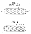
- Fig. l is a sectional view showing the typical structure of a multicore optical fiber of the sort aforementioned, wherein glass fibers l for optical transmission respectively covered with covering layers 2 are further equipped with a common covering layer 3 to form a tape-shaped optical coated fiber.
- the multicore optical fiber is coupled to another member, e.g., an ordinary single core optical fiber or another multicore optical fiber, however, the form of a tape is difficult to handle and further the problem of transmission loss resulting from the connection of both also arises. In consequence, the common covering layer 3 must be removed to handle each element together.
- the glass fibers without the covering layer suffer from insufficient strength and may cause trouble such as breakage.
- it is prerequisite to remove the common covering layer 3 of the multicore optical fiber in such a manner that the covering layer 2 of each element perfectly remaines as it is and is also undamaged.
- the covering layers 2 and the common covering layer 3 are made of the same material. Even if they are not bonded chemically but bonded merely under pressure, it is hardly possible to remove only the common covering layer 3 while the covering layer of each optical fiber is left unremoved completely.
- Another known arrangement is to form a covering layer 2 of thermosetting sillicone resin on each optical fiber l and then form a covering layer 3 of nylon common to the optical fibers, in order to provide a multicore optical fiber.
- the operation of removing the common covering layer 3 from the multicore optical fiber of that type is considerably easy because the covering layer 3 is relatively readily peeled off the covering layers 2.
- thermosetting silicone resin used for the covering layer 2 of the optical fiber thus constructed is extremely low, the covering layer of each optical fiber element after the removal of the common covering layer can not withstand rubbing or scratching and thus unsuitable for practical use.
- the normal way of removing the common covering layer 3 of the conventional multicore optical fiber is, for instance, to vertically tear the common covering layer 3 into two pieces from both left- and right-hand ends A, A ⁇ with respect to the section shown in Fig. l.
- the thickness of the common covering layer 3, excluding its portions respectively penetrating into the gaps between the optical fiber elements l and the covering layers 2 is practically uniform and therefore the common covering layer 3 will not readily be detached by simply pulling the halves thereof in certain directions.
- the removal of the common covering layer of the multicore optical fiber is indeed troublesome work.
- An object of the present invention is to provide a multicore optical fiber, e.g., a tape-shaped optical coated fiber equipped with a common covering layer readily removable and covering layers capable of respectively effectively protecting optical fiber elements contained therein.
- the multicore optical fiber according to the present invention comprises a plurality of parallel optical fiber elements respectively equipped with covering layers, a common covering layer used for integrally covering the plurality of optical fiber elements, and a thin peel layer as the outermost layer of each optical fiber element for preventing both covering layers from adhering or pressure welding to each other.
- the multicore optical fiber according to the present invention is arranged so that the substantial thickness of the common covering layer is made small locally over the whole length of the optical fiber at symmetric positions with respect to the cross section thereof.
- the novel multicore optical fiber according to the present invention is such that the peel layer is provided as the outermost layer of each optical fiber constituting the multicore optical fiber, so that the common covering layer can readily be peeled from the covering layer of each optical fiber. Accordingly, the common covering layer can readily be removed from the covering layer of each optical fiber without damaging the latter.
- the peel layer sandwiched between each optical fiber and the common covering layer functions so as to prevent both from press welding to each other and each optical fiber can sufficiently maintain its property by the covering layer of each fiber element.
- the multicore optical fiber prepared according to the present invention is provided with thin portions locally in the common layer. Accordingly, when the common covering layer is removed from the multicore optical fiber, if tensile force is applied in the direction perpendicular to a line connecting the thinned portions of the common covering layer, each optical fiber element is easily exposed since the common covering layer naturally tears from the thinned portions.
- the thinned portions may be located anywhere to attain the intended purpose as long as the common covering layer is halved with respect to the section.
- the common covering layer should be preferably tore at both ends of the plane on which the optical fiber elements are disposed.
- Resin material for use in forming a covering layer on each single core optical fiber should be strong enough to protect the optical fiber and various materials conventionally used to form the protective layer of the optical fiber may be employed.
- Typical materials include thermoplastic resin such as nylon and ultraviolet-curing resin such as urethane acrylate.
- thermosetting or photo-setting properties such as ultraviolet-curing properties and easy moldability, and further properties which prevent its adherence and press-welding to a common covering layer or the covering layer of each optical fiber.
- the material resins used as the peel layer include peeling agents prepared from ultraviolet-curing or thermosetting silicone resin, or ultraviolet-curing or thermosetting fluorocarbon resin.
- the silicone or fluorocarbon resin for use in this case is an organic compound containing silicon (Si) or fluorine (F) atoms in each molecule and can be hardened when exposed to heat or light, the hardened resin having excellent peel properties.
- the peel layer is generally less than 20 ⁇ m and preferably less than l0 ⁇ m thick. The reason for this is that, because the peel layer does not always have the protective function to the fiber element, it should preferably be as thin as possible. Also, if the peel layer is excessively thick, it will exert an unfavorable influence on the transmission characteristics of the fiber element and moreover may be damaged or peeled off as a result of friction or the like. On the contrary, the peel layer should preferably be thick enough to separate the common covering layer from the covering layer of each optical fiber element.
- the bond strength of the peel layer relative to an adjoining layer i.e., the covering layer of each fiber element or common layer
- the bond strength thereof relative to the former should preferably be, if anything, greater.
- the reason for this is attributed to the fact that, because the peel layer has to be destroyed for the removal of the common covering layer in case the peel layer clings to the common layer, undesirable stress acts on the element then. Also, part of the peel layer thus damaged is allowed to remain on the element side, which will necessitate the additional operation of removing the remnants of the peel layer from the element deprived of the common covering layer.
- Fig. 2 is a sectional view showing the construction of a multicore optical fiber according to the first embodiment of the present invention.
- a plurality of signal core optical fibers l0 are disposed in parallel on the same plane, each optical fiber being equipped with a covering layer 20, and incorporated in a covering layer 30 common to them in order to form a multicore optical fiber.
- Each optical fiber l0 is equipped with a peel layer 40 on the outer periphery of the covering layer 20. The optical fiber elements are arranged so that the adjacent peel layers 40 is made contact with each other.
- the optical fiber l0 is a glass fiber with l25 ⁇ m diameter for optical transmission and the covering layer 20 is made of ultraviolet-curing urethane acrylate, so that a signal core optical fiber with 245 ⁇ m diameter is formed.
- the optical fiber l0 equipped with the covering layer 20 was further passed through a coating die filled with ultraviolet-curing peel layer material to form the peel layer 40.
- the die used had a hole diameter of 260 ⁇ m, whereas ultraviolet-curing silicone acrylate was used as the peel layer material.
- the ultraviolet curing a l20 W/cm high pressure mercury vapor lamp was used to apply ultraviolet ray irradiation for about five seconds and an optical fiber element with 25l ⁇ m diameter equipped with the peel layer 40 was obtained.
- the common covering layer 30 was formed by applying ultraviolet-curing urethane acrylate and providing ultraviolet ray irradiation.
- the common covering layer 30 of the multicore optical fiber thus constructed could be removed easily by tearing the left- and right-hand ends of the section shown in Fig. 2 and the covering layer free from damage and having sufficient protective strength was left on each optical fiber element deprived of the common covering layer.
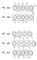
- Fig. 3(a) is a sectional view showing the structure of a multicore optical fiber according to the second embodiment of the present invention, wherein like reference characters designate like parts of Fig. 2.
- the optical fiber in this embodiment was formed of the same material and through the same process as in the case of the multicore optical fiber shown in Fig. 2, except that the upper and lower thickness T A of the common covering 30 was 0.05 mm, whereas the thickness T B at the left- and right-hand ends was 0.03 mm.
- Fig. 3(b) shows another modification, wherein the sectional shape of the common covering layer 30 was made rectangular, and wherein the thickness of a portion forming a face perpendicular to the direction in which the inner optical fiber elements were disposed was made substantially thinner than a portion forming a face parallel to the direction in which the inner optical fiber elements were disposed.
- Figs. 3(a) and 3(b) shows the multicore optical fibers with the adjoining optical fiber elements in contact with each other
- the present invention is applicable to any multicore optical fiber having the common covering layer. More specifically, if the common covering layer 30 is discontinuous at the gap 50 as shown in Fig. 4(a) or even if it is continuous between the optical fiber elements but sufficiently thin as shown in Fig. 4(b), it can readily be separated and removed. Further, as shown in Fig. 4(c), the gap 60 may be formed in portions between the optical fiber element l0 and the common covering layer 30.
- the multicore optical fiber according to the present invention is supplied with the peel layer for preventing the covering layer provided for each optical fibers and the common covering layer for integrating the optical fibers to form the multicore optical fiber from press-welding or adhering to each other. Accordingly, even though the common covering layer is removed for connecting purposes, the complete covering layer on each optical fiber is allowed to remain, and the connecting operation can be conducted easily for a short time.
- the multicore optical fiber according to the present invention is equipped with the peel layer and the common covering layer, a part of which is made substantially thin. Accordingly, even though the common covering layer is removed for connecting purposes, the complete covering layer on each optical fiber is allowed to remain, and the connecting operation can be conducted easily for a short time.
Abstract
Description
- The present invention relates to a novel multicore optical fiber suitable for high density optical communications and more particularly to a multicore optical fiber such as a tape-shaped optical coated fiber equipped with a covering layer capable of effectively protecting each optical fiber element and besides easy to handle when such optical fibers are coupled together.
- With the recent advance of data communications, there has been required for signal transmission at higher speed. As an example of materialization of such high speed signal transmission technology, the recent practical use of optical communications can be cited. The optical signal transmission has many advantages from the standpoint of communications in that the property of light itself is utilizable for realizing high speed transmission and that optical fibers used as transmission lines are lightweight and little affected by magnetic or electric field. However, such an optical fiber is still required for increasing the capacity of signal transmission and, under the circumstances, there have been proposed various kinds of optical fibers for signal transmission.
- A multicore optical fiber is one of the results realized under such circumstances. The multicore optical fiber, which is formed by integrating fiber elements as optical waveguides with a covering layer common to them, is now spotlighted as what is capable of realizing high density signal transmission with simple care in handling.
- Fig. l is a sectional view showing the typical structure of a multicore optical fiber of the sort aforementioned, wherein glass fibers l for optical transmission respectively covered with covering
layers 2 are further equipped with a common coveringlayer 3 to form a tape-shaped optical coated fiber. - In the prior art, the formed=said covering
layers - When the multicore optical fiber is coupled to another member, e.g., an ordinary single core optical fiber or another multicore optical fiber, however, the form of a tape is difficult to handle and further the problem of transmission loss resulting from the connection of both also arises. In consequence, the common covering
layer 3 must be removed to handle each element together. - On the other hand, the glass fibers without the covering layer suffer from insufficient strength and may cause trouble such as breakage. Thus, when each element is handled, it is prerequisite to remove the common covering
layer 3 of the multicore optical fiber in such a manner that the coveringlayer 2 of each element perfectly remaines as it is and is also undamaged. - In the case of the conventional multicore optical fiber, however, the covering
layers 2 and the common coveringlayer 3 are made of the same material. Even if they are not bonded chemically but bonded merely under pressure, it is hardly possible to remove only the common coveringlayer 3 while the covering layer of each optical fiber is left unremoved completely. - In consequence, not only high degree of skill but also many workhours have been required to couple multicore optical fibers.
- Another known arrangement is to form a covering
layer 2 of thermosetting sillicone resin on each optical fiber l and then form a coveringlayer 3 of nylon common to the optical fibers, in order to provide a multicore optical fiber. The operation of removing the common coveringlayer 3 from the multicore optical fiber of that type is considerably easy because the coveringlayer 3 is relatively readily peeled off thecovering layers 2. - However, because the mechanical strength of the thermosetting silicone resin used for the covering
layer 2 of the optical fiber thus constructed is extremely low, the covering layer of each optical fiber element after the removal of the common covering layer can not withstand rubbing or scratching and thus unsuitable for practical use. - The normal way of removing the common covering
layer 3 of the conventional multicore optical fiber is, for instance, to vertically tear the common coveringlayer 3 into two pieces from both left- and right-hand ends A, Aʹ with respect to the section shown in Fig. l. However, the thickness of the common coveringlayer 3, excluding its portions respectively penetrating into the gaps between the optical fiber elements l and thecovering layers 2, is practically uniform and therefore the common coveringlayer 3 will not readily be detached by simply pulling the halves thereof in certain directions. Ever if it is attempted to tear the common covering layer into two pieces from cut points made in the edges thereof with a knife and the like, the common covering layer is not always caused to tear in the longitudinal direction of the optical fiber. The removal of the common covering layer of the multicore optical fiber is indeed troublesome work. - An object of the present invention is to provide a multicore optical fiber, e.g., a tape-shaped optical coated fiber equipped with a common covering layer readily removable and covering layers capable of respectively effectively protecting optical fiber elements contained therein.
- More specifically, the multicore optical fiber according to the present invention comprises a plurality of parallel optical fiber elements respectively equipped with covering layers, a common covering layer used for integrally covering the plurality of optical fiber elements, and a thin peel layer as the outermost layer of each optical fiber element for preventing both covering layers from adhering or pressure welding to each other.
- Moreover, the multicore optical fiber according to the present invention is arranged so that the substantial thickness of the common covering layer is made small locally over the whole length of the optical fiber at symmetric positions with respect to the cross section thereof.
- The novel multicore optical fiber according to the present invention is such that the peel layer is provided as the outermost layer of each optical fiber constituting the multicore optical fiber, so that the common covering layer can readily be peeled from the covering layer of each optical fiber. Accordingly, the common covering layer can readily be removed from the covering layer of each optical fiber without damaging the latter.
- Moreover, the peel layer sandwiched between each optical fiber and the common covering layer functions so as to prevent both from press welding to each other and each optical fiber can sufficiently maintain its property by the covering layer of each fiber element.
- Furthermore, the multicore optical fiber prepared according to the present invention is provided with thin portions locally in the common layer. Accordingly, when the common covering layer is removed from the multicore optical fiber, if tensile force is applied in the direction perpendicular to a line connecting the thinned portions of the common covering layer, each optical fiber element is easily exposed since the common covering layer naturally tears from the thinned portions.
- In view of the function of the common covering layer caused to be torn in its thinned portions first, the thinned portions may be located anywhere to attain the intended purpose as long as the common covering layer is halved with respect to the section. However, since the actual optical fiber is relatively as thin as several millimeters in the maximum dimension and, in consideration of workability during the operation, the common covering layer should be preferably tore at both ends of the plane on which the optical fiber elements are disposed.
-
- Fig. l is a sectional view showing the structure of a conventional multicore optical fiber.
- Fig. 2 is a sectional view showing the structure of a multicore optical fiber according to the first embodiment of the present invention.
- Figs. 3(a) and 3(b) are sectional views showing the structure of multicore optical fibers according to the second embodiment of the present invention.
- Figs. 4(a), 4(b) and 4(c) are sectional views showing the structure of other modified multicore optical fibers according to the second embodiment of the present invention.
- Resin material for use in forming a covering layer on each single core optical fiber should be strong enough to protect the optical fiber and various materials conventionally used to form the protective layer of the optical fiber may be employed. Typical materials include thermoplastic resin such as nylon and ultraviolet-curing resin such as urethane acrylate.
- As materials for use in forming a peel layer, use can be made of various resins having thermosetting or photo-setting properties such as ultraviolet-curing properties and easy moldability, and further properties which prevent its adherence and press-welding to a common covering layer or the covering layer of each optical fiber.
- The material resins used as the peel layer include peeling agents prepared from ultraviolet-curing or thermosetting silicone resin, or ultraviolet-curing or thermosetting fluorocarbon resin. The silicone or fluorocarbon resin for use in this case is an organic compound containing silicon (Si) or fluorine (F) atoms in each molecule and can be hardened when exposed to heat or light, the hardened resin having excellent peel properties.
- The peel layer is generally less than 20 µm and preferably less than l0 µm thick. The reason for this is that, because the peel layer does not always have the protective function to the fiber element, it should preferably be as thin as possible. Also, if the peel layer is excessively thick, it will exert an unfavorable influence on the transmission characteristics of the fiber element and moreover may be damaged or peeled off as a result of friction or the like. On the contrary, the peel layer should preferably be thick enough to separate the common covering layer from the covering layer of each optical fiber element.
- With respect to the bond strength of the peel layer relative to an adjoining layer, i.e., the covering layer of each fiber element or common layer, it does not cause inconvenience whether one is greater than or equal to the other but the bond strength thereof relative to the former should preferably be, if anything, greater. The reason for this is attributed to the fact that, because the peel layer has to be destroyed for the removal of the common covering layer in case the peel layer clings to the common layer, undesirable stress acts on the element then. Also, part of the peel layer thus damaged is allowed to remain on the element side, which will necessitate the additional operation of removing the remnants of the peel layer from the element deprived of the common covering layer.
- It should further be understood that the formation of multi-covering layers or peel layers are within the technical scope of the prevent invention.
- Referring now to the accompanying drawings, a concrete description will given to a multicore optical fiber embodying the present invention, which should not be construed as limiting the scope of the present invention.
- Fig. 2 is a sectional view showing the construction of a multicore optical fiber according to the first embodiment of the present invention.
- As shown in Fig. 2, a plurality of signal core optical fibers l0 are disposed in parallel on the same plane, each optical fiber being equipped with a covering
layer 20, and incorporated in a coveringlayer 30 common to them in order to form a multicore optical fiber. Each optical fiber l0 is equipped with apeel layer 40 on the outer periphery of thecovering layer 20. The optical fiber elements are arranged so that theadjacent peel layers 40 is made contact with each other. - The optical fiber l0 is a glass fiber with l25 µm diameter for optical transmission and the
covering layer 20 is made of ultraviolet-curing urethane acrylate, so that a signal core optical fiber with 245 µm diameter is formed. - In the case of the optical fiber according to the present invention, the optical fiber l0 equipped with the covering
layer 20 was further passed through a coating die filled with ultraviolet-curing peel layer material to form thepeel layer 40. The die used had a hole diameter of 260 µm, whereas ultraviolet-curing silicone acrylate was used as the peel layer material. As for the ultraviolet curing, a l20 W/cm high pressure mercury vapor lamp was used to apply ultraviolet ray irradiation for about five seconds and an optical fiber element with 25l µm diameter equipped with thepeel layer 40 was obtained. - Five optical fiber elements l0 respectively equipped with covering
layers 20 and thepeel layers 40 were arranged in parallel and incorporated in the common coveringlayer 30 to form a multicore optical fiber. The common coveringlayer 30 was formed by applying ultraviolet-curing urethane acrylate and providing ultraviolet ray irradiation. - The
common covering layer 30 of the multicore optical fiber thus constructed could be removed easily by tearing the left- and right-hand ends of the section shown in Fig. 2 and the covering layer free from damage and having sufficient protective strength was left on each optical fiber element deprived of the common covering layer. - Fig. 3(a) is a sectional view showing the structure of a multicore optical fiber according to the second embodiment of the present invention, wherein like reference characters designate like parts of Fig. 2. The optical fiber in this embodiment was formed of the same material and through the same process as in the case of the multicore optical fiber shown in Fig. 2, except that the upper and lower thickness TA of the
common covering 30 was 0.05 mm, whereas the thickness TB at the left- and right-hand ends was 0.03 mm. - In the multicore optical fiber thus constructed, since the
peel layer 40 is sandwiched between theprotective covering layer 20 of each optical fiber element and thecommon covering layer 30, both were prevented from adhering or press-welding to each other and the removal of thecommon covering layer 30 was easy. Moreover, the complete protective layer free from defects was left on each optical fiber deprived of the common covering layer. - Fig. 3(b) shows another modification, wherein the sectional shape of the
common covering layer 30 was made rectangular, and wherein the thickness of a portion forming a face perpendicular to the direction in which the inner optical fiber elements were disposed was made substantially thinner than a portion forming a face parallel to the direction in which the inner optical fiber elements were disposed. - Although Figs. 3(a) and 3(b) shows the multicore optical fibers with the adjoining optical fiber elements in contact with each other, the present invention is applicable to any multicore optical fiber having the common covering layer. More specifically, if the
common covering layer 30 is discontinuous at thegap 50 as shown in Fig. 4(a) or even if it is continuous between the optical fiber elements but sufficiently thin as shown in Fig. 4(b), it can readily be separated and removed. Further, as shown in Fig. 4(c), thegap 60 may be formed in portions between the optical fiber element l0 and thecommon covering layer 30. - As set forth above, the multicore optical fiber according to the present invention is supplied with the peel layer for preventing the covering layer provided for each optical fibers and the common covering layer for integrating the optical fibers to form the multicore optical fiber from press-welding or adhering to each other. Accordingly, even though the common covering layer is removed for connecting purposes, the complete covering layer on each optical fiber is allowed to remain, and the connecting operation can be conducted easily for a short time.
- Moreover, the multicore optical fiber according to the present invention is equipped with the peel layer and the common covering layer, a part of which is made substantially thin. Accordingly, even though the common covering layer is removed for connecting purposes, the complete covering layer on each optical fiber is allowed to remain, and the connecting operation can be conducted easily for a short time.
- In consequence, it becomes possible to enlarge the applicability of the multicore optical fiber having numerous merits and such a demerit that a high degree of skill is required for handling. That is, the range of applications of optical communication technology and cosequently the practicability of a large volume of data transmission can be further advanced according to the present invention.
Claims (6)
a plurality of optical fiber elements disposed in parallel, each optical fiber element being equipped with a covering layer;
a common covering layer integrally covering the plurality of optical fiber elements; and
a peel layer provided on the outermost layer of each optical fiber element.
Applications Claiming Priority (6)
| Application Number | Priority Date | Filing Date | Title |
|---|---|---|---|
| JP12022386U JPS6326812U (en) | 1986-08-05 | 1986-08-05 | |
| JP12022386U | 1986-08-05 | ||
| JP120223/86U | 1986-08-05 | ||
| JP12658486U | 1986-08-20 | ||
| JP1986126584U JPH0440179Y2 (en) | 1986-08-20 | 1986-08-20 | |
| JP126584/86U | 1986-08-20 |
Publications (4)
| Publication Number | Publication Date |
|---|---|
| EP0262340A2 true EP0262340A2 (en) | 1988-04-06 |
| EP0262340A3 EP0262340A3 (en) | 1990-05-02 |
| EP0262340B1 EP0262340B1 (en) | 1995-11-08 |
| EP0262340B2 EP0262340B2 (en) | 2000-07-19 |
Family
ID=26457832
Family Applications (1)
| Application Number | Title | Priority Date | Filing Date |
|---|---|---|---|
| EP87111336A Expired - Lifetime EP0262340B2 (en) | 1986-08-05 | 1987-08-05 | Optical ribbon cable with multiple elements |
Country Status (6)
| Country | Link |
|---|---|
| US (1) | US4828349A (en) |
| EP (1) | EP0262340B2 (en) |
| KR (1) | KR880003203A (en) |
| AU (1) | AU595632B2 (en) |
| CA (1) | CA1301509C (en) |
| DE (1) | DE3751584T3 (en) |
Cited By (21)
| Publication number | Priority date | Publication date | Assignee | Title |
|---|---|---|---|---|
| EP0349206A2 (en) * | 1988-06-30 | 1990-01-03 | AT&T Corp. | Bonded array of transmission media |
| FR2672699A1 (en) * | 1991-02-13 | 1992-08-14 | Alcatel Cable | Fibre-optic ribbon |
| EP0614099A2 (en) * | 1993-03-04 | 1994-09-07 | Sumitomo Electric Industries, Ltd | Coated optical fiber unit |
| WO1994023323A1 (en) * | 1993-04-05 | 1994-10-13 | Nokia Kaapeli Oy | Optical fibre ribbon |
| DE19512511A1 (en) * | 1995-04-04 | 1996-10-10 | Coia Gmbh | Linear-matrix optical glass fibre continuous mfr. |
| EP0699933A3 (en) * | 1994-08-26 | 1997-01-02 | At & T Corp | Cable core with optical fibre |
| WO1997018493A1 (en) * | 1995-11-13 | 1997-05-22 | Lightguide Materials, Inc. | Matrix compounds for forming optical fiber ribbons |
| EP0780712A2 (en) * | 1995-12-20 | 1997-06-25 | Borden Chemical, Inc. | Peelable bonded ribbon matrix material; optical fiber bonded ribbon arrays containing same; and process for preparing said optical fiber bonded ribbon arrays |
| EP0897332A1 (en) * | 1996-06-03 | 1999-02-24 | Corning Incorporated | Enhanced ribbon strippability using coating additives |
| US5998497A (en) * | 1995-11-28 | 1999-12-07 | Dsm N.V. | Liquid photocurable resin composition |
| US6040357A (en) * | 1998-05-28 | 2000-03-21 | Dsm N.V. | Method of making a radiation-curable ink composition, radiation-curable ink composition and ribbon assembly |
| US6085010A (en) * | 1997-06-11 | 2000-07-04 | Dsm N.V. | Optical glass fiber ribbon assemblies and radiation-curable compositions for use in forming ribbon assemblies |
| US6110593A (en) * | 1998-05-21 | 2000-08-29 | Dsm N.V. | Radiation-curable optical fiber primary coating system |
| US6130980A (en) * | 1997-05-06 | 2000-10-10 | Dsm N.V. | Ribbon assemblies and ink coating compositions for use in forming the ribbon assemblies |
| US6197422B1 (en) | 1997-05-06 | 2001-03-06 | Dsm, N.V. | Ribbon assemblies and radiation-curable ink compositions for use in forming the ribbon assemblies |
| US6222969B1 (en) | 1996-06-03 | 2001-04-24 | Corning Incorporated | Enhanced ribbon strippability using coating additives |
| US6298189B1 (en) | 1996-11-08 | 2001-10-02 | Dsm N.V. | Radiation-curable optical glass fiber coating compositions, coated optical glass fibers, and optical glass fiber assemblies |
| US6301415B1 (en) | 1997-08-14 | 2001-10-09 | Dsm N.V | Optical glass fiber ribbon assemblies, matrix forming compositions radiation-curable compositions |
| EP1156352A1 (en) * | 2000-05-19 | 2001-11-21 | CCS Technology, Inc. | Method of fabricating an optical fibre ribbon cable |
| US6391936B1 (en) | 1997-12-22 | 2002-05-21 | Dsm N.V. | Radiation-curable oligomers radiation-curable compositions, coated optical glass fibers, and ribbon assemblies |
| EP1910876A2 (en) * | 2005-08-04 | 2008-04-16 | Corning Cable Systems LLC | Mechanically strippable upcoated optical fiber |
Families Citing this family (32)
| Publication number | Priority date | Publication date | Assignee | Title |
|---|---|---|---|---|
| CA1307144C (en) * | 1987-06-03 | 1992-09-08 | Akira Nishimura | Coated optical fiber tape |
| JPS643805U (en) * | 1987-06-19 | 1989-01-11 | ||
| US5074643A (en) * | 1989-12-13 | 1991-12-24 | At&T Bell Laboratories | Article comprising a nonpigmented cured color coating |
| US5383100A (en) * | 1991-08-02 | 1995-01-17 | Kikos; J. Peter | Multi-channel tubular display package |
| FR2688318B1 (en) * | 1992-03-06 | 1997-01-10 | Alcatel Cable | MULTI-GUIDE OPTICAL CONDUCTOR. |
| GB2271859B (en) * | 1992-10-21 | 1995-10-18 | Northern Telecom Ltd | Optical fibre cable comprising stack of ribbon fibre elements |
| JP3314495B2 (en) * | 1993-01-14 | 2002-08-12 | 住友電気工業株式会社 | Optical fiber ribbon |
| DE4312121B4 (en) * | 1993-04-14 | 2004-04-15 | CCS Technology, Inc., Wilmington | Optical cable with several optical fibers arranged in a given structure |
| JPH07113915A (en) * | 1993-10-20 | 1995-05-02 | Sumitomo Electric Ind Ltd | Separating tool for multifiber coated optical fiber ribbon |
| KR100248137B1 (en) * | 1994-05-24 | 2000-03-15 | 야마모토 카즈모토 | Plastic fiber bundle for optical communication |
| US5604834A (en) * | 1994-06-16 | 1997-02-18 | Sumitomo Electric Lightwave Corp. | Method of midspan and/or end entry to access selected optical fibers within an optical ribbon fiber |
| US5600750A (en) * | 1994-08-19 | 1997-02-04 | Sumitomo Electric Lightwave Corp. | Method for midspan entry of optical ribbon fiber |
| CA2131219C (en) * | 1994-08-31 | 2003-01-28 | Tsuyoshi Nonaka | Coated optical fiber |
| FR2754354B1 (en) * | 1996-10-08 | 1998-11-06 | France Telecom | CONNECTION DEVICE FOR MULTI-CORE OPTICAL FIBER, BASED ON OPTICAL ELEMENTS IN FREE SPACE |
| FR2764994B1 (en) * | 1997-06-19 | 1999-08-06 | Alsthom Cge Alcatel | OPTICAL CONDUCTOR AND OPTICAL CONDUCTOR TAPE |
| US5966489A (en) * | 1997-06-30 | 1999-10-12 | Siecor Corporation | Fiber optic ribbon interconnect cable |
| US6035088A (en) * | 1997-09-20 | 2000-03-07 | Lucent Technologies Inc. | Method and apparatus for access of optical fibers in a ribbon |
| GB2331374A (en) * | 1997-11-18 | 1999-05-19 | Northern Telecom Ltd | A Removably Coated Optical Fibre |
| US6175677B1 (en) | 1998-04-17 | 2001-01-16 | Alcatel | Optical fiber multi-ribbon and method for making the same |
| DE69942476D1 (en) | 1998-04-30 | 2010-07-22 | Nippon Telegraph & Telephone | Optical fiber |
| US6134364A (en) * | 1998-09-18 | 2000-10-17 | Lucent Technologies Inc. | Optical fiber ribbon |
| US6334016B1 (en) | 1999-06-30 | 2001-12-25 | Alcatel | Optical fiber ribbon matrix material having optimal handling characteristics |
| JP2001033670A (en) * | 1999-07-19 | 2001-02-09 | Sumitomo Electric Ind Ltd | Optical cable |
| US6538045B1 (en) | 1999-12-23 | 2003-03-25 | Dsm N.V. | Optical fiber coating compositions containing secondary or tertiary amino silicone-containing additive |
| US6535673B1 (en) | 2000-03-30 | 2003-03-18 | Corning Cable Systems Llc | Optical fiber arrays having an interface characteristic |
| US6539151B2 (en) * | 2000-08-21 | 2003-03-25 | Corning, Incorporated | Method for making separable multiple core optical fibers, the resulting fiber structures, and uses thereof |
| WO2004008215A1 (en) * | 2002-07-15 | 2004-01-22 | Tomoegawa Paper Co., Ltd. | Optical fiber tape core and production method therfor |
| US7845860B2 (en) | 2008-01-10 | 2010-12-07 | Hewlett-Packard Development Company, L.P. | Method for connecting multicore fibers to optical devices |
| KR101448574B1 (en) * | 2008-05-07 | 2014-10-08 | 휴렛-팩커드 디벨롭먼트 컴퍼니, 엘.피. | Optical engine for point-to-point communications |
| US9120693B2 (en) | 2010-11-08 | 2015-09-01 | Corning Incorporated | Multi-core optical fiber ribbons and methods for making the same |
| CN104871052B (en) * | 2012-11-26 | 2019-05-14 | 住友电气工业株式会社 | Optical waveguide, optical cable and optical module |
| US9529168B2 (en) | 2013-07-26 | 2016-12-27 | Corning Optical Communications LLC | Fiber optic ribbon |
Citations (7)
| Publication number | Priority date | Publication date | Assignee | Title |
|---|---|---|---|---|
| US3984172A (en) * | 1973-10-23 | 1976-10-05 | Bell Telephone Laboratories, Incorporated | Optical fiber transmission medium |
| FR2382155A7 (en) * | 1977-02-28 | 1978-09-22 | Fort Francois | SHEATHED OPTICAL FIBER |
| DE2724536A1 (en) * | 1977-05-31 | 1978-12-14 | Siemens Ag | RIBBON OR FLAT CABLES WITH OPTICAL TRANSMISSION ELEMENTS |
| JPS5898707A (en) * | 1981-12-09 | 1983-06-11 | Nippon Telegr & Teleph Corp <Ntt> | Optical tape core |
| JPS58115402A (en) * | 1981-12-28 | 1983-07-09 | Nippon Telegr & Teleph Corp <Ntt> | Optical fiber core |
| EP0116140A1 (en) * | 1982-12-10 | 1984-08-22 | DeSOTO, INC. | Strippable coatings for optical fiber |
| DE3526823A1 (en) * | 1985-07-26 | 1987-02-05 | Siemens Ag | Element having a plurality of optical fibres |
Family Cites Families (7)
| Publication number | Priority date | Publication date | Assignee | Title |
|---|---|---|---|---|
| US4346145A (en) * | 1981-01-05 | 1982-08-24 | Western Electric Co., Inc. | Coating composition and coated articles |
| JPS58126506A (en) * | 1982-01-22 | 1983-07-28 | Nippon Telegr & Teleph Corp <Ntt> | Multilayer piled type rectangular optical core |
| JPS60153014A (en) * | 1984-01-23 | 1985-08-12 | Nippon Telegr & Teleph Corp <Ntt> | Optical fiber unit |
| JPS60154204A (en) * | 1984-01-24 | 1985-08-13 | Sumitomo Electric Ind Ltd | Multicore optical fiber and its manufacture |
| US4592955A (en) * | 1984-10-31 | 1986-06-03 | At&T Technologies, Inc. | Insulating covering for strand material |
| GB8506499D0 (en) * | 1985-03-13 | 1985-04-17 | Telephone Cables Ltd | Optical fibre assemblies/cables |
| JPS6254206A (en) * | 1985-07-31 | 1987-03-09 | Furukawa Electric Co Ltd:The | Covered optical fiber |
-
1987
- 1987-08-03 KR KR1019870008492A patent/KR880003203A/en not_active Application Discontinuation
- 1987-08-04 AU AU76536/87A patent/AU595632B2/en not_active Ceased
- 1987-08-04 US US07/081,443 patent/US4828349A/en not_active Expired - Lifetime
- 1987-08-04 CA CA000543673A patent/CA1301509C/en not_active Expired - Fee Related
- 1987-08-05 EP EP87111336A patent/EP0262340B2/en not_active Expired - Lifetime
- 1987-08-05 DE DE3751584T patent/DE3751584T3/en not_active Expired - Fee Related
Patent Citations (7)
| Publication number | Priority date | Publication date | Assignee | Title |
|---|---|---|---|---|
| US3984172A (en) * | 1973-10-23 | 1976-10-05 | Bell Telephone Laboratories, Incorporated | Optical fiber transmission medium |
| FR2382155A7 (en) * | 1977-02-28 | 1978-09-22 | Fort Francois | SHEATHED OPTICAL FIBER |
| DE2724536A1 (en) * | 1977-05-31 | 1978-12-14 | Siemens Ag | RIBBON OR FLAT CABLES WITH OPTICAL TRANSMISSION ELEMENTS |
| JPS5898707A (en) * | 1981-12-09 | 1983-06-11 | Nippon Telegr & Teleph Corp <Ntt> | Optical tape core |
| JPS58115402A (en) * | 1981-12-28 | 1983-07-09 | Nippon Telegr & Teleph Corp <Ntt> | Optical fiber core |
| EP0116140A1 (en) * | 1982-12-10 | 1984-08-22 | DeSOTO, INC. | Strippable coatings for optical fiber |
| DE3526823A1 (en) * | 1985-07-26 | 1987-02-05 | Siemens Ag | Element having a plurality of optical fibres |
Non-Patent Citations (3)
| Title |
|---|
| "IOOC-ECOC '85",Istituto Internazionale delle Comunicazioni October 1985, Genova pages 379 - 382; M.Mirasawa et al.: "DESIGN OF FIBER TAPE WITH IMPROVED LATERAL PESSURE RESISTANCE" * |
| PATENT ABSTRACTS OF JAPAN vol. 7, no. 198 (P-220)(1343) 02 September 1983; & JP-A-58 098 707 (NIPPON DENSHIN DENWA KOSHA) 11 June 1983 * |
| PATENT ABSTRACTS OF JAPAN vol. 7, no. 224 (P-227)(1369) 05 October 1983; & JP-A-58 115 402 (NIPPON DENSHIN DENWA KOSHA) 09 July 1983 * |
Cited By (34)
| Publication number | Priority date | Publication date | Assignee | Title |
|---|---|---|---|---|
| EP0349206A3 (en) * | 1988-06-30 | 1990-09-05 | AT&T Corp. | Bonded array of transmission media |
| EP0349206A2 (en) * | 1988-06-30 | 1990-01-03 | AT&T Corp. | Bonded array of transmission media |
| EP0922980A3 (en) * | 1988-06-30 | 1999-10-20 | AT&T Corp. | Bonded array of transmission media |
| EP0922980A2 (en) * | 1988-06-30 | 1999-06-16 | AT&T Corp. | Bonded array of transmission media |
| FR2672699A1 (en) * | 1991-02-13 | 1992-08-14 | Alcatel Cable | Fibre-optic ribbon |
| US5621838A (en) * | 1993-03-04 | 1997-04-15 | Sumitomo Electric Industries, Ltd. | Resins for coated optical fiber units |
| EP0614099A2 (en) * | 1993-03-04 | 1994-09-07 | Sumitomo Electric Industries, Ltd | Coated optical fiber unit |
| EP0614099A3 (en) * | 1993-03-04 | 1995-06-28 | Sumitomo Electric Industries | Coated optical fiber unit. |
| WO1994023323A1 (en) * | 1993-04-05 | 1994-10-13 | Nokia Kaapeli Oy | Optical fibre ribbon |
| EP0699933A3 (en) * | 1994-08-26 | 1997-01-02 | At & T Corp | Cable core with optical fibre |
| DE19512511A1 (en) * | 1995-04-04 | 1996-10-10 | Coia Gmbh | Linear-matrix optical glass fibre continuous mfr. |
| WO1997018493A1 (en) * | 1995-11-13 | 1997-05-22 | Lightguide Materials, Inc. | Matrix compounds for forming optical fiber ribbons |
| US5998497A (en) * | 1995-11-28 | 1999-12-07 | Dsm N.V. | Liquid photocurable resin composition |
| EP0780712A2 (en) * | 1995-12-20 | 1997-06-25 | Borden Chemical, Inc. | Peelable bonded ribbon matrix material; optical fiber bonded ribbon arrays containing same; and process for preparing said optical fiber bonded ribbon arrays |
| EP0780712A3 (en) * | 1995-12-20 | 1998-06-17 | Borden Chemical, Inc. | Peelable bonded ribbon matrix material; optical fiber bonded ribbon arrays containing same; and process for preparing said optical fiber bonded ribbon arrays |
| EP0897332A1 (en) * | 1996-06-03 | 1999-02-24 | Corning Incorporated | Enhanced ribbon strippability using coating additives |
| EP0897332A4 (en) * | 1996-06-03 | 2000-08-23 | Corning Inc | Enhanced ribbon strippability using coating additives |
| US6222969B1 (en) | 1996-06-03 | 2001-04-24 | Corning Incorporated | Enhanced ribbon strippability using coating additives |
| US6298189B1 (en) | 1996-11-08 | 2001-10-02 | Dsm N.V. | Radiation-curable optical glass fiber coating compositions, coated optical glass fibers, and optical glass fiber assemblies |
| US6339666B2 (en) | 1996-11-08 | 2002-01-15 | Dsm N.V. | Radiation-curable optical glass fiber coating compositions, coated optical glass fibers, and optical glass fiber assemblies |
| US6661959B2 (en) | 1996-11-08 | 2003-12-09 | Dsm N.V. | Radiation-curable optical glass fiber coating compositions, coated optical glass fibers, and optical glass fiber assemblies |
| US6130980A (en) * | 1997-05-06 | 2000-10-10 | Dsm N.V. | Ribbon assemblies and ink coating compositions for use in forming the ribbon assemblies |
| US6197422B1 (en) | 1997-05-06 | 2001-03-06 | Dsm, N.V. | Ribbon assemblies and radiation-curable ink compositions for use in forming the ribbon assemblies |
| US6085010A (en) * | 1997-06-11 | 2000-07-04 | Dsm N.V. | Optical glass fiber ribbon assemblies and radiation-curable compositions for use in forming ribbon assemblies |
| US6301415B1 (en) | 1997-08-14 | 2001-10-09 | Dsm N.V | Optical glass fiber ribbon assemblies, matrix forming compositions radiation-curable compositions |
| US6391936B1 (en) | 1997-12-22 | 2002-05-21 | Dsm N.V. | Radiation-curable oligomers radiation-curable compositions, coated optical glass fibers, and ribbon assemblies |
| US6110593A (en) * | 1998-05-21 | 2000-08-29 | Dsm N.V. | Radiation-curable optical fiber primary coating system |
| US6534557B2 (en) | 1998-05-21 | 2003-03-18 | Dsm N.V. | Radiation-curable, optical fiber primary coating system |
| US6169126B1 (en) | 1998-05-21 | 2001-01-02 | Dsm N.V. | Radiation-curable optical fiber primary coating system |
| US6040357A (en) * | 1998-05-28 | 2000-03-21 | Dsm N.V. | Method of making a radiation-curable ink composition, radiation-curable ink composition and ribbon assembly |
| EP1156352A1 (en) * | 2000-05-19 | 2001-11-21 | CCS Technology, Inc. | Method of fabricating an optical fibre ribbon cable |
| US6565685B2 (en) | 2000-05-19 | 2003-05-20 | Ccs Technology, Inc. | Process for manufacture of an optical ribbon conductor from several optical conductors |
| EP1910876A2 (en) * | 2005-08-04 | 2008-04-16 | Corning Cable Systems LLC | Mechanically strippable upcoated optical fiber |
| EP1910876A4 (en) * | 2005-08-04 | 2009-11-25 | Corning Cable Sys Llc | Mechanically strippable upcoated optical fiber |
Also Published As
| Publication number | Publication date |
|---|---|
| US4828349A (en) | 1989-05-09 |
| DE3751584D1 (en) | 1995-12-14 |
| KR880003203A (en) | 1988-05-14 |
| DE3751584T2 (en) | 1996-03-21 |
| AU7653687A (en) | 1988-02-11 |
| DE3751584T3 (en) | 2001-02-22 |
| CA1301509C (en) | 1992-05-26 |
| EP0262340B2 (en) | 2000-07-19 |
| EP0262340B1 (en) | 1995-11-08 |
| AU595632B2 (en) | 1990-04-05 |
| EP0262340A3 (en) | 1990-05-02 |
Similar Documents
| Publication | Publication Date | Title |
|---|---|---|
| US4828349A (en) | Multicore optical fiber | |
| US5970196A (en) | Fiber optic protective member with removable section to facilitate separation thereof | |
| US5611017A (en) | Fiber optic ribbon cable with pre-installed locations for subsequent connectorization | |
| US4900126A (en) | Bonded array of transmission media | |
| US6097866A (en) | Optical fiber ribbon | |
| EP0290253B1 (en) | Method of and apparatus for securing elongate members of generally cylindrical form in end-to-end relationship | |
| JP2602617Y2 (en) | A device that binds multiple fibers into a ribbon | |
| US6160941A (en) | Method of manufacturing a multi-ribbon optical fiber structure that can be separated into at least two optical fiber ribbons | |
| JPS63200109A (en) | Tape-shaped optical fiber core | |
| JPH0440179Y2 (en) | ||
| JP2637411B2 (en) | Optical fiber tape outer coating stripping method | |
| JP2000147340A (en) | Two-fiber cable | |
| JPS6249310A (en) | Optical fiber tube unit | |
| KR910000240Y1 (en) | Multicore optical fiber | |
| JPH11326645A (en) | Jig and method for lump cladding removal for optical fiber ribbon | |
| JPH11202174A (en) | Coated optical fiber tapes | |
| JP3966383B2 (en) | Single core separation tool for tape core, single core separation method and branch core | |
| JP2002174759A (en) | Coated optical fiber tape | |
| JPH10148741A (en) | Optical fiber ribbon | |
| JPH09113735A (en) | Bobbin take-up structure for optical fiber | |
| JP3521571B2 (en) | Single-core separating device and single-core separating method for tape core | |
| JP2000028830A (en) | Working table for removal integral coating of optical coated fiber ribbon and method for removing integral coating | |
| JPH01319714A (en) | Coated optical fiber | |
| JP2000047072A (en) | Method for adding coated fiber identification code of coated optical fiber | |
| JPH07209550A (en) | Optical waveguide module |
Legal Events
| Date | Code | Title | Description |
|---|---|---|---|
| PUAI | Public reference made under article 153(3) epc to a published international application that has entered the european phase |
Free format text: ORIGINAL CODE: 0009012 |
|
| AK | Designated contracting states |
Kind code of ref document: A2 Designated state(s): DE FR GB |
|
| PUAL | Search report despatched |
Free format text: ORIGINAL CODE: 0009013 |
|
| AK | Designated contracting states |
Kind code of ref document: A3 Designated state(s): DE FR GB |
|
| 17P | Request for examination filed |
Effective date: 19900625 |
|
| 17Q | First examination report despatched |
Effective date: 19911213 |
|
| GRAA | (expected) grant |
Free format text: ORIGINAL CODE: 0009210 |
|
| AK | Designated contracting states |
Kind code of ref document: B1 Designated state(s): DE FR GB |
|
| REF | Corresponds to: |
Ref document number: 3751584 Country of ref document: DE Date of ref document: 19951214 |
|
| ET | Fr: translation filed | ||
| PLBI | Opposition filed |
Free format text: ORIGINAL CODE: 0009260 |
|
| PLBF | Reply of patent proprietor to notice(s) of opposition |
Free format text: ORIGINAL CODE: EPIDOS OBSO |
|
| 26 | Opposition filed |
Opponent name: ALCATEL KABEL BETEILIGUNGS-AG Effective date: 19960807 |
|
| PLBF | Reply of patent proprietor to notice(s) of opposition |
Free format text: ORIGINAL CODE: EPIDOS OBSO |
|
| PLAW | Interlocutory decision in opposition |
Free format text: ORIGINAL CODE: EPIDOS IDOP |
|
| APAC | Appeal dossier modified |
Free format text: ORIGINAL CODE: EPIDOS NOAPO |
|
| APAE | Appeal reference modified |
Free format text: ORIGINAL CODE: EPIDOS REFNO |
|
| APAC | Appeal dossier modified |
Free format text: ORIGINAL CODE: EPIDOS NOAPO |
|
| PLBQ | Unpublished change to opponent data |
Free format text: ORIGINAL CODE: EPIDOS OPPO |
|
| PLAB | Opposition data, opponent's data or that of the opponent's representative modified |
Free format text: ORIGINAL CODE: 0009299OPPO |
|
| R26 | Opposition filed (corrected) |
Opponent name: ALCATEL Effective date: 19960807 |
|
| PLAB | Opposition data, opponent's data or that of the opponent's representative modified |
Free format text: ORIGINAL CODE: 0009299OPPO |
|
| APAC | Appeal dossier modified |
Free format text: ORIGINAL CODE: EPIDOS NOAPO |
|
| PLAW | Interlocutory decision in opposition |
Free format text: ORIGINAL CODE: EPIDOS IDOP |
|
| R26 | Opposition filed (corrected) |
Opponent name: ALCATEL KABEL BETEILIGUNGS-AG Effective date: 19960807 |
|
| PUAH | Patent maintained in amended form |
Free format text: ORIGINAL CODE: 0009272 |
|
| STAA | Information on the status of an ep patent application or granted ep patent |
Free format text: STATUS: PATENT MAINTAINED AS AMENDED |
|
| 27A | Patent maintained in amended form |
Effective date: 20000719 |
|
| AK | Designated contracting states |
Kind code of ref document: B2 Designated state(s): DE FR GB |
|
| REG | Reference to a national code |
Ref country code: GB Ref legal event code: IF02 |
|
| PGFP | Annual fee paid to national office [announced via postgrant information from national office to epo] |
Ref country code: DE Payment date: 20050728 Year of fee payment: 19 |
|
| PGFP | Annual fee paid to national office [announced via postgrant information from national office to epo] |
Ref country code: GB Payment date: 20050803 Year of fee payment: 19 |
|
| PGFP | Annual fee paid to national office [announced via postgrant information from national office to epo] |
Ref country code: FR Payment date: 20050809 Year of fee payment: 19 |
|
| APAH | Appeal reference modified |
Free format text: ORIGINAL CODE: EPIDOSCREFNO |
|
| PG25 | Lapsed in a contracting state [announced via postgrant information from national office to epo] |
Ref country code: DE Free format text: LAPSE BECAUSE OF NON-PAYMENT OF DUE FEES Effective date: 20070301 |
|
| GBPC | Gb: european patent ceased through non-payment of renewal fee |
Effective date: 20060805 |
|
| REG | Reference to a national code |
Ref country code: FR Ref legal event code: ST Effective date: 20070430 |
|
| PG25 | Lapsed in a contracting state [announced via postgrant information from national office to epo] |
Ref country code: GB Free format text: LAPSE BECAUSE OF NON-PAYMENT OF DUE FEES Effective date: 20060805 |
|
| PG25 | Lapsed in a contracting state [announced via postgrant information from national office to epo] |
Ref country code: FR Free format text: LAPSE BECAUSE OF NON-PAYMENT OF DUE FEES Effective date: 20060831 |