EP0268397B1 - Carbon-plastic electrode elements - Google Patents
Carbon-plastic electrode elements Download PDFInfo
- Publication number
- EP0268397B1 EP0268397B1 EP87309484A EP87309484A EP0268397B1 EP 0268397 B1 EP0268397 B1 EP 0268397B1 EP 87309484 A EP87309484 A EP 87309484A EP 87309484 A EP87309484 A EP 87309484A EP 0268397 B1 EP0268397 B1 EP 0268397B1
- Authority
- EP
- European Patent Office
- Prior art keywords
- graphite
- bipolar
- composite
- resin
- mixture
- Prior art date
- Legal status (The legal status is an assumption and is not a legal conclusion. Google has not performed a legal analysis and makes no representation as to the accuracy of the status listed.)
- Expired - Lifetime
Links
Images

Classifications
-
- H—ELECTRICITY
- H01—ELECTRIC ELEMENTS
- H01M—PROCESSES OR MEANS, e.g. BATTERIES, FOR THE DIRECT CONVERSION OF CHEMICAL ENERGY INTO ELECTRICAL ENERGY
- H01M12/00—Hybrid cells; Manufacture thereof
- H01M12/08—Hybrid cells; Manufacture thereof composed of a half-cell of a fuel-cell type and a half-cell of the secondary-cell type
- H01M12/085—Zinc-halogen cells or batteries
-
- H—ELECTRICITY
- H01—ELECTRIC ELEMENTS
- H01M—PROCESSES OR MEANS, e.g. BATTERIES, FOR THE DIRECT CONVERSION OF CHEMICAL ENERGY INTO ELECTRICAL ENERGY
- H01M4/00—Electrodes
- H01M4/86—Inert electrodes with catalytic activity, e.g. for fuel cells
- H01M4/96—Carbon-based electrodes
-
- H—ELECTRICITY
- H01—ELECTRIC ELEMENTS
- H01M—PROCESSES OR MEANS, e.g. BATTERIES, FOR THE DIRECT CONVERSION OF CHEMICAL ENERGY INTO ELECTRICAL ENERGY
- H01M8/00—Fuel cells; Manufacture thereof
- H01M8/02—Details
- H01M8/0202—Collectors; Separators, e.g. bipolar separators; Interconnectors
- H01M8/0204—Non-porous and characterised by the material
- H01M8/0213—Gas-impermeable carbon-containing materials
-
- Y—GENERAL TAGGING OF NEW TECHNOLOGICAL DEVELOPMENTS; GENERAL TAGGING OF CROSS-SECTIONAL TECHNOLOGIES SPANNING OVER SEVERAL SECTIONS OF THE IPC; TECHNICAL SUBJECTS COVERED BY FORMER USPC CROSS-REFERENCE ART COLLECTIONS [XRACs] AND DIGESTS
- Y02—TECHNOLOGIES OR APPLICATIONS FOR MITIGATION OR ADAPTATION AGAINST CLIMATE CHANGE
- Y02E—REDUCTION OF GREENHOUSE GAS [GHG] EMISSIONS, RELATED TO ENERGY GENERATION, TRANSMISSION OR DISTRIBUTION
- Y02E60/00—Enabling technologies; Technologies with a potential or indirect contribution to GHG emissions mitigation
- Y02E60/10—Energy storage using batteries
-
- Y—GENERAL TAGGING OF NEW TECHNOLOGICAL DEVELOPMENTS; GENERAL TAGGING OF CROSS-SECTIONAL TECHNOLOGIES SPANNING OVER SEVERAL SECTIONS OF THE IPC; TECHNICAL SUBJECTS COVERED BY FORMER USPC CROSS-REFERENCE ART COLLECTIONS [XRACs] AND DIGESTS
- Y02—TECHNOLOGIES OR APPLICATIONS FOR MITIGATION OR ADAPTATION AGAINST CLIMATE CHANGE
- Y02E—REDUCTION OF GREENHOUSE GAS [GHG] EMISSIONS, RELATED TO ENERGY GENERATION, TRANSMISSION OR DISTRIBUTION
- Y02E60/00—Enabling technologies; Technologies with a potential or indirect contribution to GHG emissions mitigation
- Y02E60/30—Hydrogen technology
- Y02E60/50—Fuel cells
-
- Y—GENERAL TAGGING OF NEW TECHNOLOGICAL DEVELOPMENTS; GENERAL TAGGING OF CROSS-SECTIONAL TECHNOLOGIES SPANNING OVER SEVERAL SECTIONS OF THE IPC; TECHNICAL SUBJECTS COVERED BY FORMER USPC CROSS-REFERENCE ART COLLECTIONS [XRACs] AND DIGESTS
- Y02—TECHNOLOGIES OR APPLICATIONS FOR MITIGATION OR ADAPTATION AGAINST CLIMATE CHANGE
- Y02P—CLIMATE CHANGE MITIGATION TECHNOLOGIES IN THE PRODUCTION OR PROCESSING OF GOODS
- Y02P70/00—Climate change mitigation technologies in the production process for final industrial or consumer products
- Y02P70/50—Manufacturing or production processes characterised by the final manufactured product
-
- Y—GENERAL TAGGING OF NEW TECHNOLOGICAL DEVELOPMENTS; GENERAL TAGGING OF CROSS-SECTIONAL TECHNOLOGIES SPANNING OVER SEVERAL SECTIONS OF THE IPC; TECHNICAL SUBJECTS COVERED BY FORMER USPC CROSS-REFERENCE ART COLLECTIONS [XRACs] AND DIGESTS
- Y10—TECHNICAL SUBJECTS COVERED BY FORMER USPC
- Y10T—TECHNICAL SUBJECTS COVERED BY FORMER US CLASSIFICATION
- Y10T428/00—Stock material or miscellaneous articles
- Y10T428/30—Self-sustaining carbon mass or layer with impregnant or other layer
Abstract
Description
- The present invention relates to a method of making a bipolar element for electrochemical cells, comprising the steps of: dry mixing electrically conductive graphite particles and thermoplastic resin particles, said graphite and said resin being in a weight ratio of from 1:5 to 1:1, and compression moulding said mixture to form said bipolar element.
- There has been great interest in the development of a zinc bromide battery as an energy storage device because of the potential for its simplicity of design, high theoretical voltage, and low cost of reactants. In such a battery the energy is stored by electrolysing an aqueous zinc-bromide cell on charge to form zinc metal and bromine liquid. During charge bromine is evolved at the cathode and dissolved in the electrolyte while zinc metal is deposited on the anode. On discharge the two reactants are consumed to form zinc bromide.
- An exemplary zinc bromide battery consists of a stack of flow frame assemblies wherein a carbon bipolar electrode is bonded into each frame. The flow channels in the frames direct electrolyte past the anode and cathode side of each electrode. One side of each electrode is usually a flat surface on which zinc is deposited and consumed while the other side of the electrode may comprise a carbon felt to support the bromine evolution and consumption reactions. A porous separator is maintained between the positive and negative sides of the adjacent electrodes to prevent bromine from diffusing from the positive electrolyte to the negative electrolyte, each of which is maintained in a separate flow system.
- During charge of the battery a method of storage is required to remove generated bromine from the catholyte, to avoid increase in bromine concentration to levels of self-discharge and corrosion of cell components. Thus, bromine is stored as a complex with a quaternary ammonium bromide salt so that up to four bromine molecules can reversibly complex with the salt. The unbrominated quaternary salt is soluble in aqueous electrolyte while the polybromide complex is insoluble and separates out in a heavier oil-like phase. The organic complexing agent flows in a separate flow loop and is not pumped through the cell stack. Contact between the catholyte and complexing agent is accomplished by dispersing the complexing agent into droplets in a mixer external to the cell stack, thus increasing the area for bromine transfer between the two phases. An exemplary zinc bromide battery stack utilizing this sytsem is disclosed in U.S. Patent No. 4 162 351.
- It is, however, desirable to scale up current zinc bromide technology to meet costs and performance requirements on a large scale, as for example for a power utility load levelling mission. To meet these requirements it is important to improve not only the efficiency of the design of the battery but also to improve the system lifetime, and in particular the lifetime of components which are subjected to particularly stressful conditions. One of these components is the bipolar electrode. The commonly used component for this purpose is a vitreous carbon electrode which, particularly when scaled to the sizes required to meet industrial uses, is brittle, difficult to bond into flow frames and overall is one of the most expensive components in the cell stack. In addition, chemical stability is an issue which must be addressed in order to improve the lifetime of this component.
- Chemical Abstracts, Vol. 101, 1984 at pages 154 and 155, abstract No. 101: 233 257h discloses a plastic electrode formed by kneading a plastic material with a conductive material of carbon black and graphite, where the graphite content in the electrode is at least 15%. Specifically, polyethylene and 20% graphite are mentioned.
- U.S. Patent No. 4 551 267 discloses an electrode for a metal-halogen battery where the electrode is formed from a composition consisting essentially of a base resin polymer, carbon black, and graphite, with absorptive active carbon added. The active carbon is added to suppress diffusion of the halogen, such as bromine. The proportions of resin, carbon black, graphite and active carbon are 50%, 30%, 20%, and 10%. A comparative example containing no active carbon is described as consisting of 50% resin, 20% carbon black, and 30% graphite. The resin used is polyethylene in all the examples disclosed, and polypropylene and ethylene-propylene copolymer are mentioned generally.
- Bipolar current collector-separators for electromechanical cells containing graphite and thermoplastic fluoropolymers are disclosed in U.S. Patents Nos. 4 214 969 and 4 339 332. A bipolar plate substrate for an electrochemical cell containing glassy carbon and a plastic such as polyvinylidene fluoride homopolymer is disclosed in U.S. Patent No. 4 098 967. The above patents, however, are not directed to bipolar electrodes which meet the requirements of low cost, durability, and good electrical performance in a zinc bromide battery for large industrial application.
- According to the present invention, a method of the type defined hereinbefore at the beginning is characterised in that said graphite has a particle size distribution of 0 to 45 µm, said graphite further being heat-treated at a temperature of at least 800°C for 2 hours; and by the steps of screening the mixture to form a particle mixture of average particle size of 0 to 45 µm; and compression moulding said screened mixture under a pressure of at least 400 kg/cm² (3.92 × 10⁴ KPa) at 190°C to form said bipolar element.
- The present invention provides bipolar electrodes which have improved stability to a stringent electrochemical cell environment, particularly to a zinc-bromide cell environment, and the bipolar electrodes may be scaled up to large industrial applications while maintaining or improving physical strength, chemical stability to electrochemical cell environment, electrical performance, and component longevity.
- In a preferred embodiment of the present invention a combination of a bipolar electrode and carbon felt for use in electrochemical cells is provided.
- The bipolar elements comprise a pressure-molded composite of heat-treated electrically conductive graphite particles having a particle size distribution (before molding) of 0 to 45 µm the graphite being heat-treated at a temperature of at least 800°C for 2 hours prior to forming the composite; and thermoplastic resin particles, the graphite and resin in the composite being in a weight ratio of from 1:5 to 1:1, i.e., there being from one to five times as much resin as graphite by weight. The composite has less than 4.0% weight loss and less than 0.1% dimensional increase in length upon immersion at 60°C into polybromide oil for 1600 hours. The composite is formed by pressure-molding a mixture comprising the graphite and resin at 400kg/cm² (3.92 × 10⁴ KPa) at 190°C. An assembly can be provided comprising the above described bipolar current collecting element and a composite felt held in interfacial contact with each other with an adhesive.
- A preferred method according to the invention provides a pressure-molded bipolar electrode element which is a composite of heat treated electrically conductive graphite particles and thermoplastic resin particles, in a weight ratio of from 1:5 to 1:1. The bipolar element is characterised by improved chemical stability to conditions within an electrochemical cell, particularly within zinc bromide electrochemical cell. This has improved stability as manifested by chemical stability in polybromide oil utilised in a zinc bromide cell, as for example, described in U.S. Patent No. 4 162 351. At a temperature of 60°C upon immersion into this oil for 1600 hours, the electrodes are characterised by less than 4.0% weight loss and less than 0.1% dimensional increase in length. The bipolar electrodes are also characterised by excellent physical strength and chemical characteristics for an electrochemical cell. In particular the bipolar electrodes are characterised, after immersion in polybromide oil at 60°C for 2300 hours, by resistivity of less than 0.8 ohm-cm and a flexural strength of at least 2400 psi (168.7 kg/cm²) (1.65 × 10⁴ KPa). One component of the bipolar electrodes is graphite having a particle size distribution of 0 to 45 µm. The graphite is also heat treated at a temperature of at least 800°C for 2 hours prior to being processed into a composite. It is critical that the graphite have the above characteristics and be heat treated in order to obtain the proper chemical, electrical and physical characteristics in accordance with the invention. Graphite meeting the above characteristics of particle size distribution is available commercially from Asbury Graphite Mills, Inc. (Asbury, N.J.).
- The thermoplastic resin particles may be any thermoplastic fluoropolymer, and in particular a polyvinylidene difluoride. Fluoropolymer resins such as tetrafluoroethylene, and the like, are commercially available and may be utilised in place of polyvinylidene difluoride although the polyvinylidene difluoride is preferable. A suitable polyvinylidene difluoride is available under the trade name Kynar, from PennWalt Corporation. The particle size distribution of the thermoplastic resin particles is also critical, and have a particle size distribution in the range of about 0 to 45 µm.
- Typically the heat treated graphite particles will be dry mixed with the thermoplastic resin particles and compression moulded into a composite under 400 kg/cm² 3.92 × 10⁴ KPa or higher pressure at 190°C with gradual cooling.
- The composite will contain graphite particles and resin particles in the weight ratio of 1:5 to 1:1. The preferred weight ratio is 1:1.
- In one embodiment of the present invention, the bipolar electrode may be formed into an assembly with a composite carbon felt. The carbon felt will be held in interfacial contact with the bipolar electrode by an adhesive material which is stable to the conditions within the electrochemical cell. Preferably this adhesive will comprise carbon (carbon black or graphite), polyvinylidene difluoride resin and dimethylformamide. Carbon black is the preferred carbon in the adhesive. The composite carbon felt will be attached to the positive face of the bipolar electrode with the electrically conductive adhesive material. The attachment of this felt improves the performance over a loose assembly of the felt and the bipolar electrode.
- While not intending to be limited by any particular theory, it is believed that the bipolar electrodes made in accordance with the present invention with the above described graphite, exhibit a lower surface area than, for instance, an electrode made with carbon black and therefore exhibits less of a tendency for bromine absorption. Furthermore, it is believed that the thermoplastic resin shields the graphite particles from the effect of bromine and is heat resistant.
- The invention will now be described by way of example with reference to the accompanying drawings, in which:-
- Fig. 1 is a battery design shown schematically incorporating the bipolar electrodes embodying the present invention;
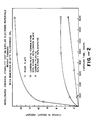
- Fig. 2 is a graph comparing the chemical stability of bipolar electrode materials embodying the present invention with a conventional rigid graphite plate and a non-graphitic carbon/plastic formulation, with respect to change in weight;
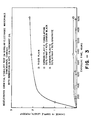
- Fig. 3 is a graph comparing the chemical stability of a bipolar electrode embodying the present invention with a rigid plate and a non-graphitic carbon/plastic formulation, with respect to change in length; and
- Fig. 4 is a flowchart illustrating the manufacturing process for bipolar electrodes embodying the present invention.
- Figure 1 is a schematic exploded view diagram of a cell component of an electrochemical battery for use in zinc bromide technology.
Frame 10 is a typical flow frame showing the positive side of the frame which is utilised to hold cell components.Flow frame 10 is usually made from heat and chemical resistant injection moulded material such a polypropylene.Bipolar electrodes plate 12A is a carbon feltcathode substrate 14. The assembly of thebipolar electrode 12A and carbon feltcathode substrate 14 comprises a preferred assembly according to the present invention. Adjacent to the carbon felt 14 is the catholyte flow. Then partially shown is a filledgasket 16 area of the separator followed by theseparator membrane 18. Bonded toseparator membrane 18 is theanode grid spacer 20, which is adjacent to a space for the flow of anolyte. Finally, there is thebipolar electrode 12B for the next adjacent cell, with the cell stack continuing, depending upon the number of cells desired in the battery stack. - The carbon felt
cathode substrate 14 is an open structure which allows flowthrough of the catholyte. - Preferably the felt will be about 97% porous. It has been found that an effective mean pore diameter in the felt of about 86 microns is preferable with a preferred range of porosity being 88% of pores distributed between 10 and 70 microns pore diameter.
- Referring to Figure 2 there is shown a graph of the results of an accelerated chemical stability test of three composite materials (molded 15 inch by 15 inch pieces) (38.1 × 38.1 cm): a rigid carbon/carbonized resin plate (represented by square data points) consisting of a sheet of phenolic resin heat treated to form a vitreous carbon; a plate formed by compression molding a mixture of 60% by weight Kynar and 40% by weight carbon black (data points represented by circles); and a plate according to the present invention formed from compression molding a mixture of 50% by weight Kynar and 50% by weight graphite having the characteristics as described herein (datapoints represented by triangles).
- The three plates were immersed in 60°C polybromide oil (a quaternary ammonium bromide salt used to complex bromide in zinc bromide cells) at 60° for 1600 hours. The increase in weight of each of the plates in terms of weight percentage is shown versus exposure time. The plate made in accordance with the present invention exhibited a less than 4% increase in weight indicating an improved weight stability.
- Referring to Figure 3 there is shown a graph of accelerated chemical stability of the same three plates as described in connection with Figure 2 under the same conditions except that changes in the length of the samples are compared. The electrode made in accordance with the present invention (data points represented by triangles) exhibited less than a 0.1% dimensional increase in length, indicating improved dimensional stability.
- Referring to Figure 4 there is illustrated a flowchart of the preferred manufacturing processes preparing bipolar electrodes according to the present invention. In one embodiment the graphite is first subjected to the step of
heat treatment 30 at a temperature of at least 800°C for a period of at least 2 hours. Then the heat treated graphite is subjected to thestep 32 of screening to ensure the particle size distribution of 0 to 45 µm. The graphite is then dry mixed instep 34 with the appropriate amount of the thermoplastic resin particles. The mixture is then screened instep 36 to ensure that the resin particles in the mixture are within the size distribution range of 0 to 45µm. The dry blend of graphite and resin is then compression molded instep 38 under pressure of at least 400 kg/cm² (3.92 × 10⁴ KPa) at 190°C with cooling in a conventional compression mold apparatus. - In a second embodiment, referring to Figure 4, in the dry mixing step 34 a small amount of a binder material is added to the dry mix. Preferably this will be a perfluorinated polymer material, preferably Teflon®. This will be added in an amount of about 2 weight percent of the total mixture. After screening in
step 36 the dry blend is then wet mixed with a hydrocarbon carrier, such as Solvent 340 (Shell) instep 40 then calendered into sheets instep 42. The sheets are then dried instep 44 and submitted to thecompression molding step 38 as described above. In this embodiment, by loading the mold with a preform calendered sheet, the material uniformity over the area of the electrode is improved and the inclusion of airborne particulates in the composite is reduced. - The following example is provided by way of illustration and is not intended to limi t the invention in any way.
- A mixture of 250 g of polyvinylidene difluoride, sold under the trade name of Kynar by the PennWalt Corporation and 250 g of a graphite, (artificial), sold under the name A-99, by Asbury Graphite Mills, Inc., having been pretreated at 800°C in air for 2 hours, were dry mixed. The graphite was previously screened through a 325 mesh screen to ensure the particle size distribution of 0 to 45µm. To the dry mixture of graphite and polyvinylidene difluoride resin was added 8 gms of particulate Teflon®. The dry mixture containing these three components was screened through a 20 mesh screen then mixed with 250 ml of Shell Solvent 340 as a hydrocarbon carrier. The wet mixture was calendered between rollers to form sheets. The sheets were dried at 20°C for 168 hours then placed into a compression mold and molded into 15X15 inch (38.1 × 38.1 cm) plates under 400 kg/cm² (3.92 × 10⁴ KPa) pressure at 190°C. The mold was gradually cooled during compression. The formed plates had a compressed thickness of 40 mils (0.10 cm).
Claims (12)
- A method of making a bipolar element for electrochemical cells, comprising the steps of:
dry mixing (34) electrically conductive graphite particles and thermoplastic resin particles, said graphite and said resin being in a weight ratio of from 1:5 to 1:1; and compression moulding said mixture to form said bipolar element, characterised in that said graphite has a particle size distribution of 0 to 45µm, said graphite further being heat-treated (30) at a temperature of at least 800°C for 2 hours; and by the steps of screening (36) the mixture to form a particle mixture of average particle size of 0 to 45 µm; and compression moulding (38) said screened mixture under a pressure of at least 400 kg/cm² (3.92 × 10⁴ KPa) at 190°C to form said bipolar element. - A method according to claim 1, characterised in that said thermoplastic resin particles comprise polyvinylidene difluoride.
- A method according to claim 1 or 2, characterised in that the dry mixing (34) is carried out with up to 2% by weight of a perfluorohydrocarbon binder; and by the steps of forming (40) a wet mixture of the particulate mixture with a liquid hydrocarbon carrier and calendering (42) said wet mixture into sheets; drying (44) said sheets; and compression moulding (38) said sheets.
- A method according to claim 3, characterised in that said perfluorohydrocarbon binder comprises polytetrafluoroethylene.
- A bipolar electrode element for electrochemical cells comprising:
a pressure-moulded composite (12A) of electrically conductive graphite particles and thermoplastic fluoropolymer resin particles, said graphite and said resin in said composite (12A) being in a weight ratio of from 1:5 to 1:1; characterised in that the graphite particles have a particle size distribution before moulding of 0 to 45 µm, said graphite is heat-treated (30) at a temperature of at least 800°C in air for 2 hours prior to forming said composite (12A); the thermoplastic fluoropolymer resin particles have a particle size distribution before moulding of 0 to 45 µm; said composite having less than 4.0% weight loss and less than 0.1% dimensional increase in length upon immersion at 60°C into polybromide oil for 1600 hours; and said composite (12A) being formed by pressure-moulding (38) a mixture comprising said graphite and said resin at 400 kg/cm² (3.92 × 10⁴ KPa) or above at 190°C. - A bipolar element according to claim 5, characterised by a resistivity of less than 0.8 ohm-cm and a flexural strength of at least 2400 psi (168.7 kg/cm²) (1.65 × 10⁴ KPa) upon immersion at 60°C into polybromide oil for at least 2300 hours.
- A bipolar element according to claim 5, characterised by comprising up to 2% by weight of a perfluorohydrocarbon, said graphite, said resin and said perfluorohydrocarbon being calendered (42) with a hydrocarbon carrier into preformed shapes prior to being subjected to said pressure moulding (38).
- A bipolar element according to claim 7, characterised in that said perfluorohydrocarbon comprises polytetrafluoroethylene.
- A bipolar element according to claim 5, characterised in that said thermoplastic resin comprises polyvinylidene difluoride.
- A bipolar element according to claim 9, characterised in that said graphite and said resin in said composite (12A) are in a weight ratio of 1:1.
- A bipolar assembly comprising a bipolar element (12A) according to claim 5 and a composite carbon felt (14), said felt (14) and said element (12A) being held in interfacial contact with an adhesive.
- A bipolar assembly according to claim 11, characterised in that said adhesive is formed from carbon, polyvinylidene difluoride resin and dimethylformamide.
Priority Applications (1)
| Application Number | Priority Date | Filing Date | Title |
|---|---|---|---|
| AT87309484T ATE77003T1 (en) | 1986-11-20 | 1987-10-27 | CARBON-PLASTIC ELECTRODE ELEMENTS. |
Applications Claiming Priority (2)
| Application Number | Priority Date | Filing Date | Title |
|---|---|---|---|
| US06/933,466 US4758473A (en) | 1986-11-20 | 1986-11-20 | Stable carbon-plastic electrodes and method of preparation thereof |
| US933466 | 1986-11-20 |
Publications (2)
| Publication Number | Publication Date |
|---|---|
| EP0268397A1 EP0268397A1 (en) | 1988-05-25 |
| EP0268397B1 true EP0268397B1 (en) | 1992-06-03 |
Family
ID=25464019
Family Applications (1)
| Application Number | Title | Priority Date | Filing Date |
|---|---|---|---|
| EP87309484A Expired - Lifetime EP0268397B1 (en) | 1986-11-20 | 1987-10-27 | Carbon-plastic electrode elements |
Country Status (6)
| Country | Link |
|---|---|
| US (1) | US4758473A (en) |
| EP (1) | EP0268397B1 (en) |
| JP (1) | JPS63138659A (en) |
| AT (1) | ATE77003T1 (en) |
| CA (1) | CA1282920C (en) |
| DE (1) | DE3779570T2 (en) |
Families Citing this family (50)
| Publication number | Priority date | Publication date | Assignee | Title |
|---|---|---|---|---|
| FR2574803B1 (en) * | 1984-12-18 | 1987-01-30 | Occidental Chem Co | ELECTRICALLY CONDUCTIVE THERMOPLASTIC MATERIAL AND METHOD FOR MANUFACTURING SUCH MATERIAL |
| US4920017A (en) * | 1986-11-20 | 1990-04-24 | Electric Power Research Institute, Inc. | Porous and porous-nonporous composites for battery electrodes |
| JP3012240B2 (en) * | 1987-09-25 | 2000-02-21 | 東洋紡績株式会社 | Manufacturing method of polarizable electrode material |
| DE3809758A1 (en) * | 1988-03-23 | 1989-10-05 | Dietrich Dipl Chem Dr Schuster | ORGANIC ELECTRODE MATERIAL, METHOD FOR THE PRODUCTION AND USE THEREOF |
| EP0462274A4 (en) * | 1990-01-11 | 1993-01-27 | Koa Oil Company, Limited | Production of elastic graphite molding |
| AU649894B2 (en) * | 1991-11-25 | 1994-06-02 | Shigeyuki Yasuda | Electric power generating element |
| CN1086929A (en) * | 1992-09-04 | 1994-05-18 | 单一检索有限公司 | Flexible, conducting plastic electrode and manufacture method thereof |
| AU673003B2 (en) * | 1992-09-04 | 1996-10-24 | Jd Holding Inc. | Flexible, conducting plastic electrode and process for its preparation |
| US5344727A (en) * | 1993-06-21 | 1994-09-06 | General Motors Corporation | Bipolar battery electrode |
| US5582622A (en) * | 1994-10-12 | 1996-12-10 | Bipolar Technologies, Inc. | Methods of making bipolar battery plates comprising carbon and a fluoroelastomer |
| WO1996012313A1 (en) * | 1994-10-12 | 1996-04-25 | Bipolar Technologies Corporation | Bipolar battery cells, batteries, and methods |
| US5556627A (en) * | 1994-10-12 | 1996-09-17 | Bipolar Technologies, Inc. | Bipolar battery cells, batteries and methods |
| US5582937A (en) * | 1994-10-12 | 1996-12-10 | Bipolar Technologies, Inc. | Bipolar battery cells, batteries and methods |
| DE19542721A1 (en) * | 1995-11-16 | 1997-05-22 | Sgl Technik Gmbh | Process for the production of moldings from plastic-filler mixtures with a high filler content |
| JP3359220B2 (en) * | 1996-03-05 | 2002-12-24 | キヤノン株式会社 | Lithium secondary battery |
| GB2337150B (en) * | 1998-05-07 | 2000-09-27 | Nat Power Plc | Carbon based electrodes |
| US6572997B1 (en) | 2000-05-12 | 2003-06-03 | Hybrid Power Generation Systems Llc | Nanocomposite for fuel cell bipolar plate |
| FR2812120B1 (en) | 2000-07-24 | 2006-11-03 | Commissariat Energie Atomique | CONDUCTIVE COMPOSITE MATERIAL AND ELECTRODE FOR FUEL CELL USING THE MATERIAL |
| FR2812119B1 (en) * | 2000-07-24 | 2002-12-13 | Commissariat Energie Atomique | CONDUCTIVE COMPOSITE MATERIAL AND ELECTRODE FOR FUEL CELL USING THE THERMO-COMPRESSED MATERIAL |
| AU2002360540A1 (en) * | 2001-12-04 | 2003-06-17 | University Of Southern California | Method for intracellular modifications within living cells using pulsed electric fields |
| US20030219646A1 (en) * | 2002-05-23 | 2003-11-27 | Lecostaouec Jean-Francois | Carbon fiber reinforced plastic bipolar plates with continuous electrical pathways |
| US6979513B2 (en) * | 2002-06-28 | 2005-12-27 | Firefly Energy Inc. | Battery including carbon foam current collectors |
| US7033703B2 (en) * | 2002-12-20 | 2006-04-25 | Firefly Energy, Inc. | Composite material and current collector for battery |
| US7341806B2 (en) * | 2002-12-23 | 2008-03-11 | Caterpillar Inc. | Battery having carbon foam current collector |
| US20060147712A1 (en) * | 2003-07-09 | 2006-07-06 | Maxwell Technologies, Inc. | Dry particle based adhesive electrode and methods of making same |
| US20110165318A9 (en) * | 2004-04-02 | 2011-07-07 | Maxwell Technologies, Inc. | Electrode formation by lamination of particles onto a current collector |
| US7352558B2 (en) * | 2003-07-09 | 2008-04-01 | Maxwell Technologies, Inc. | Dry particle based capacitor and methods of making same |
| US7295423B1 (en) * | 2003-07-09 | 2007-11-13 | Maxwell Technologies, Inc. | Dry particle based adhesive electrode and methods of making same |
| US20070122698A1 (en) * | 2004-04-02 | 2007-05-31 | Maxwell Technologies, Inc. | Dry-particle based adhesive and dry film and methods of making same |
| US7508651B2 (en) * | 2003-07-09 | 2009-03-24 | Maxwell Technologies, Inc. | Dry particle based adhesive and dry film and methods of making same |
| US20100014215A1 (en) * | 2004-04-02 | 2010-01-21 | Maxwell Technologies, Inc. | Recyclable dry particle based electrode and methods of making same |
| US7342770B2 (en) * | 2003-07-09 | 2008-03-11 | Maxwell Technologies, Inc. | Recyclable dry particle based adhesive electrode and methods of making same |
| US7791860B2 (en) * | 2003-07-09 | 2010-09-07 | Maxwell Technologies, Inc. | Particle based electrodes and methods of making same |
| US7920371B2 (en) * | 2003-09-12 | 2011-04-05 | Maxwell Technologies, Inc. | Electrical energy storage devices with separator between electrodes and methods for fabricating the devices |
| US7495349B2 (en) * | 2003-10-20 | 2009-02-24 | Maxwell Technologies, Inc. | Self aligning electrode |
| US7090946B2 (en) | 2004-02-19 | 2006-08-15 | Maxwell Technologies, Inc. | Composite electrode and method for fabricating same |
| US7384433B2 (en) | 2004-02-19 | 2008-06-10 | Maxwell Technologies, Inc. | Densification of compressible layers during electrode lamination |
| US7227737B2 (en) * | 2004-04-02 | 2007-06-05 | Maxwell Technologies, Inc. | Electrode design |
| US7440258B2 (en) * | 2005-03-14 | 2008-10-21 | Maxwell Technologies, Inc. | Thermal interconnects for coupling energy storage devices |
| US7492574B2 (en) | 2005-03-14 | 2009-02-17 | Maxwell Technologies, Inc. | Coupling of cell to housing |
| US20090233175A1 (en) * | 2005-03-31 | 2009-09-17 | Kelley Kurtis C | Current Carrier for an Energy Storage Device |
| US7572551B1 (en) | 2005-06-27 | 2009-08-11 | Greatbatch Ltd. | Electrode active blanks and methods of making |
| US8518573B2 (en) * | 2006-09-29 | 2013-08-27 | Maxwell Technologies, Inc. | Low-inductive impedance, thermally decoupled, radii-modulated electrode core |
| US20080204973A1 (en) * | 2007-02-28 | 2008-08-28 | Maxwell Technologies, Inc. | Ultracapacitor electrode with controlled iron content |
| US20080201925A1 (en) | 2007-02-28 | 2008-08-28 | Maxwell Technologies, Inc. | Ultracapacitor electrode with controlled sulfur content |
| US8399134B2 (en) * | 2007-11-20 | 2013-03-19 | Firefly Energy, Inc. | Lead acid battery including a two-layer carbon foam current collector |
| CN101567452B (en) * | 2009-04-20 | 2011-05-11 | 清华大学 | Preparation method of liquid flow battery composite material bipolar plate |
| WO2015125916A1 (en) * | 2014-02-24 | 2015-08-27 | 積水化学工業株式会社 | Carbon material, resin composite material, and method for producing said carbon material and resin composite material |
| WO2015127511A1 (en) * | 2014-02-26 | 2015-09-03 | Redflow R&D Pty Ltd | Bipolar battery electrode having improved carbon surfaces and method of manufacturing same |
| CN107331879A (en) * | 2017-07-04 | 2017-11-07 | 清华大学 | A kind of continuous manufacturing method of bipolar plate of redox flow battery |
Family Cites Families (12)
| Publication number | Priority date | Publication date | Assignee | Title |
|---|---|---|---|---|
| NL43679C (en) * | 1934-03-14 | |||
| US3589942A (en) * | 1966-12-22 | 1971-06-29 | Cons Natural Gas Svc | Bipolar collector plates |
| US3565694A (en) * | 1969-03-17 | 1971-02-23 | Yardney International Corp | Bipolar electrode and method of making same |
| CA1051512A (en) * | 1973-05-23 | 1979-03-27 | Royce E. Biddick | Bipolar electrode using electrically conductive plastic substrate containing vitreous carbon |
| US4124747A (en) * | 1974-06-04 | 1978-11-07 | Exxon Research & Engineering Co. | Conductive polyolefin sheet element |
| US4125680A (en) * | 1977-08-18 | 1978-11-14 | Exxon Research & Engineering Co. | Bipolar carbon-plastic electrode structure-containing multicell electrochemical device and method of making same |
| US4162351A (en) * | 1977-10-12 | 1979-07-24 | Electric Power Research Institute, Inc. | Metal-halogen cell operation with storage of halogen via organic complexation external to the electrochemical cell |
| US4214969A (en) * | 1979-01-02 | 1980-07-29 | General Electric Company | Low cost bipolar current collector-separator for electrochemical cells |
| US4294893A (en) * | 1979-05-21 | 1981-10-13 | Centro Ricerche Fiat S.P.A. | Graphite-resin composite electrode structure, and a process for its manufacture |
| US4339322A (en) * | 1980-04-21 | 1982-07-13 | General Electric Company | Carbon fiber reinforced fluorocarbon-graphite bipolar current collector-separator |
| US4482614A (en) * | 1982-11-15 | 1984-11-13 | Gel, Inc. | Zinc-bromine battery with long term stability |
| JPS59138067A (en) * | 1983-01-27 | 1984-08-08 | Meidensha Electric Mfg Co Ltd | Positive electrode of metal-halogen battery |
-
1986
- 1986-11-20 US US06/933,466 patent/US4758473A/en not_active Expired - Fee Related
-
1987
- 1987-10-26 CA CA000550214A patent/CA1282920C/en not_active Expired - Fee Related
- 1987-10-27 DE DE8787309484T patent/DE3779570T2/en not_active Expired - Fee Related
- 1987-10-27 EP EP87309484A patent/EP0268397B1/en not_active Expired - Lifetime
- 1987-10-27 AT AT87309484T patent/ATE77003T1/en not_active IP Right Cessation
- 1987-11-20 JP JP62293852A patent/JPS63138659A/en active Pending
Non-Patent Citations (1)
| Title |
|---|
| CHEMICAL ABSTRACTS, vol. 101, no. 26, December 24, 1984, Columbus, Ohio USA MEIDENSHA ELECTRIC MFG. CO. LTD "Plastic electrode" page 154, column 2, abstract-no. 233 257h * |
Also Published As
| Publication number | Publication date |
|---|---|
| CA1282920C (en) | 1991-04-16 |
| ATE77003T1 (en) | 1992-06-15 |
| DE3779570T2 (en) | 1993-01-28 |
| DE3779570D1 (en) | 1992-07-09 |
| US4758473A (en) | 1988-07-19 |
| EP0268397A1 (en) | 1988-05-25 |
| JPS63138659A (en) | 1988-06-10 |
Similar Documents
| Publication | Publication Date | Title |
|---|---|---|
| EP0268397B1 (en) | Carbon-plastic electrode elements | |
| US4510219A (en) | Battery plate containing filler with conductive coating | |
| US5348817A (en) | Bipolar lead-acid battery | |
| RU2182737C2 (en) | Electrochemical fuel cell (alternatives), membrane-electrode assembly (alternatives), composite material (alternatives), electrochemical fuel cell manufacturing process, and membrane-electrode assembly production process (alternatives) | |
| US4086397A (en) | Electrochemical cell and cathode for same | |
| EP1066656B1 (en) | Ion conductive matrixes and their use | |
| CA1168701A (en) | Reversible electrochemical doping of conjugated polymers, and secondary batteries based thereon | |
| AU779425B2 (en) | Electrochemical electrode for fuel cell | |
| US9105933B2 (en) | Gas diffusion electrode, method of producing same, membrane electrode assembly comprising same and method of producing membrane electrode assembly comprising same | |
| CA1278032C (en) | Cathodic electrode | |
| CA2051441A1 (en) | Conductive components containing conductive metal oxide | |
| EP1880440B1 (en) | Oxidatively stable microlayers of gas diffusion layers | |
| KR20030022126A (en) | Nanocomposite for fuel cell bipolar plate | |
| Scrosati | Conducting polymers: advanced materials for new design, rechargeable lithium batteries | |
| US4625395A (en) | Battery plate containing filler with conductive coating | |
| US4731310A (en) | Cathodic electrode | |
| US4060668A (en) | Primary electrochemical cell | |
| EP0228573B1 (en) | A surface treated electrode and a zinc-halogen secondary battery incorporating the same | |
| US3553022A (en) | Electrochemical cell | |
| Baochen et al. | Large-scale polyaniline batteries | |
| US4920017A (en) | Porous and porous-nonporous composites for battery electrodes | |
| US4818741A (en) | Porous and porous-nonporous composites for battery electrodes | |
| CA1171903A (en) | Fuel cell | |
| US20020177037A1 (en) | Method for producing a separator/electrode assembly for electrochemical elements | |
| JPS6032251A (en) | Gas electrode for fuel cell |
Legal Events
| Date | Code | Title | Description |
|---|---|---|---|
| PUAI | Public reference made under article 153(3) epc to a published international application that has entered the european phase |
Free format text: ORIGINAL CODE: 0009012 |
|
| AK | Designated contracting states |
Kind code of ref document: A1 Designated state(s): AT BE CH DE ES FR GB GR IT LI LU NL SE |
|
| 17P | Request for examination filed |
Effective date: 19881121 |
|
| 17Q | First examination report despatched |
Effective date: 19900525 |
|
| GRAA | (expected) grant |
Free format text: ORIGINAL CODE: 0009210 |
|
| AK | Designated contracting states |
Kind code of ref document: B1 Designated state(s): AT BE CH DE ES FR GB GR IT LI LU NL SE |
|
| ITF | It: translation for a ep patent filed |
Owner name: FUMERO BREVETTI S.N.C. |
|
| PG25 | Lapsed in a contracting state [announced via postgrant information from national office to epo] |
Ref country code: SE Effective date: 19920603 Ref country code: GR Free format text: LAPSE BECAUSE OF FAILURE TO SUBMIT A TRANSLATION OF THE DESCRIPTION OR TO PAY THE FEE WITHIN THE PRESCRIBED TIME-LIMIT Effective date: 19920603 Ref country code: BE Effective date: 19920603 Ref country code: AT Effective date: 19920603 |
|
| REF | Corresponds to: |
Ref document number: 77003 Country of ref document: AT Date of ref document: 19920615 Kind code of ref document: T |
|
| REF | Corresponds to: |
Ref document number: 3779570 Country of ref document: DE Date of ref document: 19920709 |
|
| ET | Fr: translation filed | ||
| PG25 | Lapsed in a contracting state [announced via postgrant information from national office to epo] |
Ref country code: ES Free format text: LAPSE BECAUSE OF FAILURE TO SUBMIT A TRANSLATION OF THE DESCRIPTION OR TO PAY THE FEE WITHIN THE PRESCRIBED TIME-LIMIT Effective date: 19920914 |
|
| PG25 | Lapsed in a contracting state [announced via postgrant information from national office to epo] |
Ref country code: GB Effective date: 19921027 |
|
| PG25 | Lapsed in a contracting state [announced via postgrant information from national office to epo] |
Ref country code: LU Free format text: LAPSE BECAUSE OF NON-PAYMENT OF DUE FEES Effective date: 19921031 Ref country code: LI Effective date: 19921031 Ref country code: CH Effective date: 19921031 |
|
| PLBE | No opposition filed within time limit |
Free format text: ORIGINAL CODE: 0009261 |
|
| STAA | Information on the status of an ep patent application or granted ep patent |
Free format text: STATUS: NO OPPOSITION FILED WITHIN TIME LIMIT |
|
| PG25 | Lapsed in a contracting state [announced via postgrant information from national office to epo] |
Ref country code: NL Effective date: 19930501 |
|
| 26N | No opposition filed | ||
| NLV4 | Nl: lapsed or anulled due to non-payment of the annual fee | ||
| GBPC | Gb: european patent ceased through non-payment of renewal fee |
Effective date: 19921027 |
|
| PG25 | Lapsed in a contracting state [announced via postgrant information from national office to epo] |
Ref country code: FR Effective date: 19930630 |
|
| REG | Reference to a national code |
Ref country code: CH Ref legal event code: PL |
|
| PG25 | Lapsed in a contracting state [announced via postgrant information from national office to epo] |
Ref country code: DE Effective date: 19930701 |
|
| REG | Reference to a national code |
Ref country code: FR Ref legal event code: ST |
|
| PG25 | Lapsed in a contracting state [announced via postgrant information from national office to epo] |
Ref country code: IT Free format text: LAPSE BECAUSE OF NON-PAYMENT OF DUE FEES;WARNING: LAPSES OF ITALIAN PATENTS WITH EFFECTIVE DATE BEFORE 2007 MAY HAVE OCCURRED AT ANY TIME BEFORE 2007. THE CORRECT EFFECTIVE DATE MAY BE DIFFERENT FROM THE ONE RECORDED. Effective date: 20051027 |