EP0274785A1 - Toilet for public use - Google Patents
Toilet for public use Download PDFInfo
- Publication number
- EP0274785A1 EP0274785A1 EP87202469A EP87202469A EP0274785A1 EP 0274785 A1 EP0274785 A1 EP 0274785A1 EP 87202469 A EP87202469 A EP 87202469A EP 87202469 A EP87202469 A EP 87202469A EP 0274785 A1 EP0274785 A1 EP 0274785A1
- Authority
- EP
- European Patent Office
- Prior art keywords
- cubicle
- usage
- toilet
- toilet bowl
- toilet according
- Prior art date
- Legal status (The legal status is an assumption and is not a legal conclusion. Google has not performed a legal analysis and makes no representation as to the accuracy of the status listed.)
- Granted
Links
Images


Classifications
-
- E—FIXED CONSTRUCTIONS
- E03—WATER SUPPLY; SEWERAGE
- E03D—WATER-CLOSETS OR URINALS WITH FLUSHING DEVICES; FLUSHING VALVES THEREFOR
- E03D9/00—Sanitary or other accessories for lavatories ; Devices for cleaning or disinfecting the toilet room or the toilet bowl; Devices for eliminating smells
- E03D9/002—Automatic cleaning devices
Abstract
Description
- The invention relates to a toilet for public use, comprising a cabin which is divided by a partition into a usage cubicle having a door to be locked from the inside and an equipment cubicle, a toilet bowl being placed in the usage cubicle, which toilet bowl is provided with a flushing device connected to a fluid-carrying line in which is mounted a regulating valve which can be opened and closed by control means.
- Such public toilet cabins for use by men and women are erected in a number of large European cities. They are made of concrete. The toilet bowl is flushed and cleaned by being folded away, after use, into the equipment cubicle, where it is cleaned and subsequently folded back into the use position. The hinge and operating mechanism necessary for this purpose is vulnerable and unsafe. Furthermore, keeping the floor and/or the toilet bowl edge clean leaves a lot to be desired.
- The invention aims at avoiding these drawbacks and at providing a toilet, mentioned in the introduction, which can be kept very clean completely automatically, without a vulnerable hinge and operating mechanism being necessary, the structure being hardly susceptible to vandalism, if at all.
- According to the invention the toilet is characterized for this purpose in that a number of nozzles for cleaning the toilet bowl edge and/or the floor of the usage cubicle open into the usage cubicle, these nozzles being connected to fluid-carrying lines having regulating valves which can be opened and closed by control means, and in that first detection means such as radar or infrared beams which are not accessible from the usage cubicle and can detect the presence and absence of a subject in the usage cubicle are placed in the equipment cubicle, these detection means being connected to the control means, all this being such that the valves in the fluid-carrying lines to the nozzles can be opened only if it is detected that somebody has been present in the usage cubicle and has left the latter.
- The bowl edge is, for example, cleaned once after each use and the floor is cleaned once after every third use. This latter figure is to be adjusted to suit the requirements.
- The successive detection of the presence and absence of a subject and the subsequent automatic cleaning of parts susceptible to contamination, in particular the edge of the toilet bowl and/or the floor, are essential to the inventive concept. The upper edge of the toilet bowl will usually need to be cleaned after each use.
- The possibility is not excluded that some delay occurs in the operation of the valves in the fluid-carrying lines to the nozzles for cleaning the toilet bowl and of the valves in the fluid-carrying lines to the nozzles for cleaning the floor, all this such that, for example, first the toilet bowl edge and subsequently the floor will be cleaned.
- It must be ensured during flushing that nobody enters the usage cubicle. Use is therefore preferably made of a door-locking mechanism connected to the control means, all this such that the locking mechanism is brought into the locked position if it is detected that somebody has been present in the usage cubicle and has left the latter. Locking of the door-locking mechanism will be a condition for opening the valves in the fluid-carrying lines to the cleaning nozzles.
- The bowl must always be flushed after use. Second detection means which are not accessible from the usage cubicle, are connected to the control means and can detect the presence of a hand, foot or the like near a given part of the wall or floor, are present in the equipment cubicle, all this such that the valve in the fluid-carrying line of the flushing device of the toilet bowl is opened if the second detection means have detected the presence of a hand, foot or the like near the said wall part.
- If flushing is not carried out by bringing a hand, foot or the like near a given part of the wall or floor, flushing is nevertheless necessary. For this reason the control means will open the valve in the fluid-carrying line of the flushing device if it is detected that somebody has been present in the usage cubicle and has left the latter without having operated the second detection means.
- After use, flushing is always preferably carried out twice, for example by the control means opening the valve in the fluid-carrying line of the flushing device of the toilet bowl during each locking of the door-locking mechanism by a subject entering the usage cubicle.
- In order to prevent the cabin from smelling as a consequence of the fact that the pores become saturated with salt which, because of their hygroscopic nature, remain moist and spread smell the cabin walls and the partition should consist of a non-porous, corrosion-resistant material. The cabin walls and the partition preferably consist of a sandwich formed from a core of plastic foam covered on either side with a hard smooth layer of polyester and/or polyurethane.
- When the toilet bowl forms an integral with the partition and has no moving parts it will be extremely difficult for malevolent subjects to damage the bowl.
- The floor of the usage cubicle and the toilet bowl edge will have to be dried after cleaning. For this purpose the toilet will be provided with means for supplying warm air to the toilet bowl edge or, as the case may be, floor of the usage cubicle, control means being present for activating the warm air supply means when the cleaning of the toilet bowl edge or, as the case may be, usage cubicle floor is finished.
- In order to be able to wash the hands, the toilet is provided with a wash basin, a water-supply nozzles near the wash basin, means, fitted in the equipment cubicle, for the supply of water to said nozzle, detection means for detecting a hand near said nozzle and activating the said water supply if the presence of a hand is detected.
- A soap dispenser is preferably placed in the vicinity of the wash basin.
- Damage to the toilet-paper holder can be avoided by placing the latter into the equipment cubicle, an opening for feeding through the paper being recessed in the partition.
- In order to make the temperature in the toilet cubicle bearable in cold weather an air-heating unit may be fitted in the equipment cubicle and air vents may be recessed in the partition, a fan being present for blowing air around the heating unit via the air vents into the usage cubicle and use being made of a thermostat control for switching on the air-heating unit at a certain air temperature.
- It is also possible for a floor-heating system controlled by a thermostat to be added.
- In order to inform those who want to use the toilet of whether the toilet is vacant or engaged or equally that they have to wait because the toilet bowl edge and/or the floor have been cleaned, illuminated indicating elements are arranged near the door of the usage cubicle.
- It is pointed out that U.S. Patent 2,688,141 describes a cabin provided with an entrance door, which cabin accommodates a toilet having an automatic flushing system. Flushing valves are operated automatically at a certain time after entry of a subject. There are switches for detecting whether the door is open or closed. However, the presence of a subject in the cabin is not detected.
- U.S. Patent 4,233,692 furthermore describes a toilet for public use, having a toilet bowl which forms an integral with the wall. There are nozzles for supplying water and cleansing agents. Electromagnetic valves in the lines are operated by fairly sensitive pushbuttons. Again, the presence of a subject is not detected.
- The invention will now be explained in detail by reference to the figures which represent an exemplary embodiment.
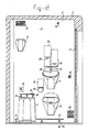
- Figure 1 shows a horizontal section through the toilet cabin.
- Figure 2 shows a section along line II-II in Figure 1.
- Figure 3 shows a view along line III-III in Figure 1.
- The public convenience shown comprises a hexagonal cabin 1, the walls, floor and roof of which are manufactured of corrosion-resistant, strong material. A sandwich of a layer of plastic foam (for example 6 cm thick polyurethane foam) covered on two sides with a smooth hard layer of polyester and/or polyurethane is particularly suitable. The cabin is divided by a
partition 2 of the same material into two cubicles: ausage cubicle 3 and anequipment cubicle 4. The two cubicles have anentrance door 5 and 6, respectively. Thedoor 5 of the usage cubicle is a sliding door lockable from the inside, while the door 6 of the equipment cubicle is a hinged door which is hardly recognisable from the outside and can be opened only by an authorized fitter or the like. - The following articles are arranged in the usage cubicle: a toilet bowl 7 which forms an integral with the
partition 2 and has no moving parts, a self-closing rubbish bin 8, a wash basin 9 having a cold-water tap 10, asoap dispenser 12, ahand dryer 13 and a clothes-peg 14. A hand support may be formed at the wall near the toilet bowl for the disabled. Furthermore, aslit 15 through which toilet paper can be dispensed by aholder 16 arranged on the rear surface of thewall 2, is arranged in thewall 2. - A flushing device 11 connected to a fluid-carrying line in which a magnetic valve 20a is housed, is present near the toilet bowl 7.
- For cleaning the upper edge of the toilet bowl 7 three sets of nozzles are arranged above the toilet bowl 7, each set comprising a
nozzle 18 for spraying water and anozzle 19 for spraying cleansing agent. These nozzles are connected to lines in which the flow is controlled by amagnetic valve 20b. - A
slit 21 which is connected to abox 22 for hot air fastened to the rear surface of the wall, is present in thewall 2 above thenozzles - A number of sets of nozzles is arranged near the floor, each set comprising a
nozzle 25 for spraying water and anozzle 26 for spraying chemical cleansing agent. These nozzles are connected to lines, not shown, in which the flow is controlled by amagnetic valve 20c.Slots 27 which are connected toboxes 28 for hot air fastened to the rear surface of thewall 2, are recessed in thewall 2 above thenozzles - The magnetic valves can be controlled by electrical control means, fitted in a
box 23, specifically control means for regulating the magnetic valve 20a, control means for regulating themagnetic valve 20b and control means for regulating themagnetic valve 20c. - An
infrared detection apparatus 24 which can detect the presence of a hand at the front face of thewall 2 in the vicinity of theapparatus 24 is fastened to the rear surface of thewall 2. In this section, the front face is provided with a pictogram representing a hand. After use of the toilet, the bowl can be flushed by bringing a hand near this pictogram. Theapparatus 24 emits a signal to control means in thebox 23 which open the magnetic valve 20a and close it after a certain period of time. If the user of the toilet does not perform the necessary manipulations for flushing the bowl provisions are made for flushing the bowl nevertheless. On opening and closing of the sliding door 5 a door-lockingswitch 41 emits a signal to the control means in thebox 23. As soon as these means have received a signal for opening and/or closing the door, the magnetic valve 20a in the line to the flushing device 11 is opened and the bowl flushed. The possibility is not excluded that these control means are programmed such that the flushing takes place, as a result of the opening and/or closing of the slidingdoor 5, only if flushing has not been done by bringing a hand near the said pictogram. The possibilities also include the fact that the toilet bowl is flushed every time the door is opened independent of whether the bowl has been flushed by bringing a hand near the pictogram. - The equipment cubicle contains an
infrared detection system 29 for detecting the presence of a subject in the usage cubicle. This system comprises, for example, four infrared detectors. A number of these can be accommodated in theboxes 28. The control means for thecontrol valves nozzles door 5 during the cleaning of the floor, by means of theswitch 41, cleaning not starting until theswitch 41 is indeed locked. - Hot air is supplied via the
slits 20 and 27, respectively after flushing of the toilet bowl and cleaning of the edge of the bowl and of the floor. The supply of hot air to theboxes box 23. Time switches present in thebox 23 can ensure that cleaning of the toilet bowl edge, cleaning of the floor and drying take place successively. For example, 2 1/2 minutes are available for the complete procedure. - A detection apparatus 30 for detecting the presence of a hand or the like is present near the
water tap 10 in the equipment cubicle. As soon as a hand is present near that apparatus the water starts to run and the water supply stops when the hand is removed. - The heating apparatus for the
hand dryer 13 is indicated by 31 and is present in the equipment cubicle. The presence or absence of a hand near thedryer 13 can be established by operatingradar 32 and the dryer switched on if necessary. - An electric air-
heating apparatus 33 which is regulated by athermostat 34, and, at a certain air temperature, can blow hot air into the usage cubicle via the slits or thegrid 35, is present in the equipment cubicle. The apparatus can consist of a separate heating system and a separate fan. - Electrical heating elements 36 regulated by a floor thermostat 37 are arranged in the floor.
-
Elements - An
emergency illumination element 42 is present at a place, which is difficult to reach, behind a solid grid. This element is fed by an emergency illumination unit in case of failure of the electrical current. - Various modifications are possible within the scope of the invention. It is important for the inventive concept that no sensitive, movable parts are arranged in the usage cubicle and that the provisions made for flushing the toilet bowl and for cleaning the edge of the bowl and the floor are essentially not accessible from the usage cubicle. Furthermore, the flushing and cleaning are progressively controlled such that contamination is impossible and subjects do not run a risk of damage to clothing by cleansing liquid. It is furthermore necessary for the cabin and the partition to consist of a corrosion-resistant, non-porous material. Various other provisions can of course also be arranged in the usage cubicle, such as a small seat for children, a drain for cleansing liquid. The entrance door to the usage cubicle can always be brought automatically into the closed position by means of a counterweight. The entrance door to the equipment cubicle will be capable of being locked and unlocked by means of a transmitter/receiver system. There is the possibility that the entrance door to the usage cubicle is locked automatically at certain times, for example at night between 1 and 7 am.
Claims (15)
Priority Applications (1)
| Application Number | Priority Date | Filing Date | Title |
|---|---|---|---|
| AT87202469T ATE56064T1 (en) | 1986-12-18 | 1987-12-09 | TOILET FOR PUBLIC USE. |
Applications Claiming Priority (2)
| Application Number | Priority Date | Filing Date | Title |
|---|---|---|---|
| NL8603230A NL8603230A (en) | 1986-12-18 | 1986-12-18 | PUBLIC TOILET. |
| NL8603230 | 1986-12-18 |
Publications (2)
| Publication Number | Publication Date |
|---|---|
| EP0274785A1 true EP0274785A1 (en) | 1988-07-20 |
| EP0274785B1 EP0274785B1 (en) | 1990-08-29 |
Family
ID=19849019
Family Applications (1)
| Application Number | Title | Priority Date | Filing Date |
|---|---|---|---|
| EP87202469A Expired - Lifetime EP0274785B1 (en) | 1986-12-18 | 1987-12-09 | Toilet for public use |
Country Status (7)
| Country | Link |
|---|---|
| EP (1) | EP0274785B1 (en) |
| JP (1) | JPH0387430A (en) |
| AT (1) | ATE56064T1 (en) |
| DE (1) | DE3764628D1 (en) |
| ES (1) | ES2018254B3 (en) |
| GR (1) | GR3001050T3 (en) |
| NL (1) | NL8603230A (en) |
Cited By (17)
| Publication number | Priority date | Publication date | Assignee | Title |
|---|---|---|---|---|
| WO1993014276A1 (en) * | 1992-01-16 | 1993-07-22 | Canadian Commercial Corporation Limited | Lavatory vent and/or cistern |
| WO1994001627A1 (en) * | 1992-07-05 | 1994-01-20 | Bel & Tom Industries (1991) Ltd. | Public toilet facility |
| DE19720759A1 (en) * | 1997-05-07 | 1998-11-19 | Berliner Stadtreinigungsbetrie | Floor cleaning and disinfecting system |
| DE19720762A1 (en) * | 1997-05-07 | 1998-11-19 | Berliner Stadtreinigungsbetrie | Public toilet module |
| US5963991A (en) * | 1997-01-22 | 1999-10-12 | Agosti; Roberto | Automatic and self-cleaning hygienic-sanitary system for public use |
| EP1494956A4 (en) * | 2002-04-09 | 2006-06-07 | Waterbury Co Inc | Dispensing system |
| WO2009039290A2 (en) * | 2007-09-20 | 2009-03-26 | Bradley Fixtures Corporation | Lavatory system |
| US7603726B2 (en) | 2005-12-20 | 2009-10-20 | S.C. Johnson & Son, Inc. | Toilet bowl cleaning and/or deodorizing device |
| US8291524B2 (en) | 2005-12-20 | 2012-10-23 | S.C, Johnson & Son, Inc. | Clip for mounting a fluid delivery device |
| US8549675B2 (en) | 2010-11-26 | 2013-10-08 | S.C. Johnson & Son, Inc. | Toilet bowl cleaning device including dual activation mechanism |
| US8740015B2 (en) | 2003-09-09 | 2014-06-03 | S.C. Johnson & Son, Inc. | Spray dispenser activated by sensed light level |
| US9758953B2 (en) | 2012-03-21 | 2017-09-12 | Bradley Fixtures Corporation | Basin and hand drying system |
| US10041236B2 (en) | 2016-06-08 | 2018-08-07 | Bradley Corporation | Multi-function fixture for a lavatory system |
| US10100501B2 (en) | 2012-08-24 | 2018-10-16 | Bradley Fixtures Corporation | Multi-purpose hand washing station |
| US11015329B2 (en) | 2016-06-08 | 2021-05-25 | Bradley Corporation | Lavatory drain system |
| CN112884950A (en) * | 2020-12-31 | 2021-06-01 | 李佳能 | Intelligent public toilet based on use distribution |
| FR3129416A1 (en) * | 2021-11-22 | 2023-05-26 | Jcdecaux Sa | health facility. |
Families Citing this family (7)
| Publication number | Priority date | Publication date | Assignee | Title |
|---|---|---|---|---|
| CN101065299B (en) | 2004-10-12 | 2012-05-23 | 约翰逊父子公司 | Compact spray device |
| US8061562B2 (en) | 2004-10-12 | 2011-11-22 | S.C. Johnson & Son, Inc. | Compact spray device |
| MX366199B (en) | 2009-10-07 | 2019-06-25 | Bradley Fixtures Corp | Lavatory system with hand dryer. |
| US9170148B2 (en) | 2011-04-18 | 2015-10-27 | Bradley Fixtures Corporation | Soap dispenser having fluid level sensor |
| US9267736B2 (en) | 2011-04-18 | 2016-02-23 | Bradley Fixtures Corporation | Hand dryer with point of ingress dependent air delay and filter sensor |
| USD663016S1 (en) | 2011-08-25 | 2012-07-03 | Bradley Fixtures Corporation | Lavatory system with integrated hand dryer |
| US9108782B2 (en) | 2012-10-15 | 2015-08-18 | S.C. Johnson & Son, Inc. | Dispensing systems with improved sensing capabilities |
Citations (6)
| Publication number | Priority date | Publication date | Assignee | Title |
|---|---|---|---|---|
| US2688141A (en) * | 1950-11-08 | 1954-09-07 | Sloan Valve Co | Automatic flushing system |
| US3755826A (en) * | 1971-10-29 | 1973-09-04 | Scr Corp | Self-cleaning rest room |
| US4233692A (en) * | 1979-10-09 | 1980-11-18 | Sinsley John D | Rest rooms |
| EP0059134A1 (en) * | 1981-02-05 | 1982-09-01 | Jean-Marie Vergnes | Sanitary unit having cleaning means |
| GB2123046A (en) * | 1982-06-28 | 1984-01-25 | Ica Spa | Self-cleaning water closet cubicle |
| EP0180236A2 (en) * | 1984-10-31 | 1986-05-07 | Toto Ltd. | Sanitary facility room for clean room |
-
1986
- 1986-12-18 NL NL8603230A patent/NL8603230A/en not_active Application Discontinuation
-
1987
- 1987-12-09 EP EP87202469A patent/EP0274785B1/en not_active Expired - Lifetime
- 1987-12-09 ES ES87202469T patent/ES2018254B3/en not_active Expired - Lifetime
- 1987-12-09 DE DE8787202469T patent/DE3764628D1/en not_active Expired - Fee Related
- 1987-12-09 AT AT87202469T patent/ATE56064T1/en not_active IP Right Cessation
- 1987-12-18 JP JP62321154A patent/JPH0387430A/en active Pending
-
1990
- 1990-11-06 GR GR90400869T patent/GR3001050T3/en unknown
Patent Citations (6)
| Publication number | Priority date | Publication date | Assignee | Title |
|---|---|---|---|---|
| US2688141A (en) * | 1950-11-08 | 1954-09-07 | Sloan Valve Co | Automatic flushing system |
| US3755826A (en) * | 1971-10-29 | 1973-09-04 | Scr Corp | Self-cleaning rest room |
| US4233692A (en) * | 1979-10-09 | 1980-11-18 | Sinsley John D | Rest rooms |
| EP0059134A1 (en) * | 1981-02-05 | 1982-09-01 | Jean-Marie Vergnes | Sanitary unit having cleaning means |
| GB2123046A (en) * | 1982-06-28 | 1984-01-25 | Ica Spa | Self-cleaning water closet cubicle |
| EP0180236A2 (en) * | 1984-10-31 | 1986-05-07 | Toto Ltd. | Sanitary facility room for clean room |
Cited By (28)
| Publication number | Priority date | Publication date | Assignee | Title |
|---|---|---|---|---|
| WO1993014276A1 (en) * | 1992-01-16 | 1993-07-22 | Canadian Commercial Corporation Limited | Lavatory vent and/or cistern |
| WO1994001627A1 (en) * | 1992-07-05 | 1994-01-20 | Bel & Tom Industries (1991) Ltd. | Public toilet facility |
| US5963991A (en) * | 1997-01-22 | 1999-10-12 | Agosti; Roberto | Automatic and self-cleaning hygienic-sanitary system for public use |
| DE19720759A1 (en) * | 1997-05-07 | 1998-11-19 | Berliner Stadtreinigungsbetrie | Floor cleaning and disinfecting system |
| DE19720762A1 (en) * | 1997-05-07 | 1998-11-19 | Berliner Stadtreinigungsbetrie | Public toilet module |
| US5857228A (en) * | 1997-05-07 | 1999-01-12 | Berliner Stadtreinigungsbetriebe | Toilet for public use |
| DE19720759C2 (en) * | 1997-05-07 | 1999-03-04 | Berliner Stadtreinigungsbetrie | Floor cleaning / disinfection system |
| DE19720762C2 (en) * | 1997-05-07 | 2001-10-31 | Berliner Stadtreinigungsbetr E | Sanitary cell with sanitary and technical room as well as procedures for cleaning and / or disinfecting the sanitary room |
| EP1494956A4 (en) * | 2002-04-09 | 2006-06-07 | Waterbury Co Inc | Dispensing system |
| AU2003233454B2 (en) * | 2002-04-09 | 2007-03-22 | Waterbury Companies Inc. | Dispensing system |
| US8740015B2 (en) | 2003-09-09 | 2014-06-03 | S.C. Johnson & Son, Inc. | Spray dispenser activated by sensed light level |
| US7895683B2 (en) | 2005-12-20 | 2011-03-01 | S.C. Johnson & Son, Inc. | Toilet bowl cleaning and/or deodorizing device |
| US8220080B2 (en) | 2005-12-20 | 2012-07-17 | S. C. Johnson & Son, Inc. | Toilet bowl cleaning and/or deodorizing device |
| US7603726B2 (en) | 2005-12-20 | 2009-10-20 | S.C. Johnson & Son, Inc. | Toilet bowl cleaning and/or deodorizing device |
| US8291524B2 (en) | 2005-12-20 | 2012-10-23 | S.C, Johnson & Son, Inc. | Clip for mounting a fluid delivery device |
| US8099800B2 (en) | 2005-12-20 | 2012-01-24 | S.C. Johnson & Son, Inc. | Toilet bowl cleaning and/or deodorizing device |
| WO2009039290A2 (en) * | 2007-09-20 | 2009-03-26 | Bradley Fixtures Corporation | Lavatory system |
| WO2009039290A3 (en) * | 2007-09-20 | 2009-08-27 | Bradley Fixtures Corporation | Lavatory system |
| GB2467661B (en) * | 2007-09-20 | 2013-02-13 | Bradley Fixtures Corp | Lavatory system |
| GB2467661A (en) * | 2007-09-20 | 2010-08-11 | Bradley Fixtures Corp | Lavatory system |
| US8549675B2 (en) | 2010-11-26 | 2013-10-08 | S.C. Johnson & Son, Inc. | Toilet bowl cleaning device including dual activation mechanism |
| US9758953B2 (en) | 2012-03-21 | 2017-09-12 | Bradley Fixtures Corporation | Basin and hand drying system |
| US10100501B2 (en) | 2012-08-24 | 2018-10-16 | Bradley Fixtures Corporation | Multi-purpose hand washing station |
| US10041236B2 (en) | 2016-06-08 | 2018-08-07 | Bradley Corporation | Multi-function fixture for a lavatory system |
| US11015329B2 (en) | 2016-06-08 | 2021-05-25 | Bradley Corporation | Lavatory drain system |
| CN112884950A (en) * | 2020-12-31 | 2021-06-01 | 李佳能 | Intelligent public toilet based on use distribution |
| CN112884950B (en) * | 2020-12-31 | 2023-05-30 | 李佳能 | Intelligent public toilet based on use distribution |
| FR3129416A1 (en) * | 2021-11-22 | 2023-05-26 | Jcdecaux Sa | health facility. |
Also Published As
| Publication number | Publication date |
|---|---|
| ATE56064T1 (en) | 1990-09-15 |
| DE3764628D1 (en) | 1990-10-04 |
| ES2018254B3 (en) | 1991-04-01 |
| EP0274785B1 (en) | 1990-08-29 |
| NL8603230A (en) | 1988-07-18 |
| JPH0387430A (en) | 1991-04-12 |
| GR3001050T3 (en) | 1992-01-20 |
Similar Documents
| Publication | Publication Date | Title |
|---|---|---|
| EP0274785A1 (en) | Toilet for public use | |
| US4336619A (en) | Hand washer and drier mounting structure | |
| US4233692A (en) | Rest rooms | |
| US4425672A (en) | Shower bath units | |
| CA1121554A (en) | Sanitary unit | |
| US4797959A (en) | Sanitary unit | |
| US4345343A (en) | Apparatus for the cleaning and sanitation of a restroom or lavoratory | |
| US5857228A (en) | Toilet for public use | |
| JP7299627B2 (en) | prefabricated sanitary module kit | |
| JPS5915139A (en) | Automatic cleaning type sanitary apparatus | |
| US4597114A (en) | Sanitary facility with means for automatic cleaning | |
| US3969133A (en) | Method for self-cleaning a restroom | |
| US20220282507A1 (en) | Sanitary installation and associated angled door | |
| JPH06123126A (en) | Toilet facility and its control method | |
| JPH034709B2 (en) | ||
| JP2018134150A (en) | Cabinet for toilet room | |
| RU1868U1 (en) | SANKABINA AUTOMATIC | |
| RU6681U1 (en) | RESTROOM | |
| JPH0349591Y2 (en) | ||
| JPH11299706A (en) | Health management system | |
| GB2200382A (en) | Apparatus for cleansing a bowl-like article or other article supported on or above a floor surface | |
| JPH0349593Y2 (en) | ||
| JP2004194999A (en) | Toilet device | |
| RU2098998C1 (en) | Lavatory module | |
| JPH0349592Y2 (en) |
Legal Events
| Date | Code | Title | Description |
|---|---|---|---|
| PUAI | Public reference made under article 153(3) epc to a published international application that has entered the european phase |
Free format text: ORIGINAL CODE: 0009012 |
|
| AK | Designated contracting states |
Kind code of ref document: A1 Designated state(s): AT BE CH DE ES FR GB GR IT LI LU NL SE |
|
| 17P | Request for examination filed |
Effective date: 19880705 |
|
| 17Q | First examination report despatched |
Effective date: 19890322 |
|
| GRAA | (expected) grant |
Free format text: ORIGINAL CODE: 0009210 |
|
| AK | Designated contracting states |
Kind code of ref document: B1 Designated state(s): AT BE CH DE ES FR GB GR IT LI LU NL SE |
|
| REF | Corresponds to: |
Ref document number: 56064 Country of ref document: AT Date of ref document: 19900915 Kind code of ref document: T |
|
| ET | Fr: translation filed | ||
| REF | Corresponds to: |
Ref document number: 3764628 Country of ref document: DE Date of ref document: 19901004 |
|
| ITF | It: translation for a ep patent filed |
Owner name: STUDIO TORTA SOCIETA' SEMPLICE |
|
| PGFP | Annual fee paid to national office [announced via postgrant information from national office to epo] |
Ref country code: GR Payment date: 19901130 Year of fee payment: 4 |
|
| REG | Reference to a national code |
Ref country code: GR Ref legal event code: FG4A Free format text: 3001050 |
|
| PLBE | No opposition filed within time limit |
Free format text: ORIGINAL CODE: 0009261 |
|
| STAA | Information on the status of an ep patent application or granted ep patent |
Free format text: STATUS: NO OPPOSITION FILED WITHIN TIME LIMIT |
|
| 26N | No opposition filed | ||
| ITTA | It: last paid annual fee | ||
| PG25 | Lapsed in a contracting state [announced via postgrant information from national office to epo] |
Ref country code: GR Free format text: THE PATENT HAS BEEN ANNULLED BY A DECISION OF A NATIONAL AUTHORITY Effective date: 19920630 |
|
| EPTA | Lu: last paid annual fee | ||
| REG | Reference to a national code |
Ref country code: GR Ref legal event code: MM2A Free format text: 3001050 |
|
| EAL | Se: european patent in force in sweden |
Ref document number: 87202469.0 |
|
| REG | Reference to a national code |
Ref country code: GB Ref legal event code: 732E |
|
| NLS | Nl: assignments of ep-patents |
Owner name: STRUYK HOLDING B.V. TE OOSTERHOUT. |
|
| REG | Reference to a national code |
Ref country code: FR Ref legal event code: TP |
|
| ITPR | It: changes in ownership of a european patent |
Owner name: CESSIONE;STRUYK HOLDING B.V. |
|
| REG | Reference to a national code |
Ref country code: CH Ref legal event code: PUE Owner name: STRUYK HOLDING B.V. |
|
| REG | Reference to a national code |
Ref country code: ES Ref legal event code: PC2A Owner name: STRUYK HOLDING B.V. |
|
| REG | Reference to a national code |
Ref country code: CH Ref legal event code: PUE Owner name: STRUYK HOLDING B.V. TRANSFER- SANITRONICS INTERNAT |
|
| REG | Reference to a national code |
Ref country code: GB Ref legal event code: 732E |
|
| NLS | Nl: assignments of ep-patents |
Owner name: SANITRONICS INTERNATIONAL HOLDING B.V. |
|
| REG | Reference to a national code |
Ref country code: ES Ref legal event code: PC2A |
|
| REG | Reference to a national code |
Ref country code: FR Ref legal event code: TP |
|
| REG | Reference to a national code |
Ref country code: CH Ref legal event code: PUE Owner name: SANITRONICS INTERNATIONAL HOLDING B.V. TRANSFER- A |
|
| REG | Reference to a national code |
Ref country code: GB Ref legal event code: 732E |
|
| REG | Reference to a national code |
Ref country code: FR Ref legal event code: TP |
|
| NLS | Nl: assignments of ep-patents |
Owner name: AWK AUSSENWERBUNG GMBH |
|
| REG | Reference to a national code |
Ref country code: ES Ref legal event code: PC2A |
|
| PGFP | Annual fee paid to national office [announced via postgrant information from national office to epo] |
Ref country code: GB Payment date: 19991208 Year of fee payment: 13 |
|
| PGFP | Annual fee paid to national office [announced via postgrant information from national office to epo] |
Ref country code: FR Payment date: 19991216 Year of fee payment: 13 |
|
| PGFP | Annual fee paid to national office [announced via postgrant information from national office to epo] |
Ref country code: AT Payment date: 19991220 Year of fee payment: 13 |
|
| PGFP | Annual fee paid to national office [announced via postgrant information from national office to epo] |
Ref country code: SE Payment date: 19991222 Year of fee payment: 13 Ref country code: BE Payment date: 19991222 Year of fee payment: 13 |
|
| PGFP | Annual fee paid to national office [announced via postgrant information from national office to epo] |
Ref country code: ES Payment date: 19991228 Year of fee payment: 13 |
|
| PGFP | Annual fee paid to national office [announced via postgrant information from national office to epo] |
Ref country code: DE Payment date: 19991229 Year of fee payment: 13 |
|
| PGFP | Annual fee paid to national office [announced via postgrant information from national office to epo] |
Ref country code: CH Payment date: 19991230 Year of fee payment: 13 |
|
| PGFP | Annual fee paid to national office [announced via postgrant information from national office to epo] |
Ref country code: NL Payment date: 19991231 Year of fee payment: 13 |
|
| PGFP | Annual fee paid to national office [announced via postgrant information from national office to epo] |
Ref country code: LU Payment date: 20000106 Year of fee payment: 13 |
|
| PG25 | Lapsed in a contracting state [announced via postgrant information from national office to epo] |
Ref country code: LU Free format text: LAPSE BECAUSE OF NON-PAYMENT OF DUE FEES Effective date: 20001209 Ref country code: GB Free format text: LAPSE BECAUSE OF NON-PAYMENT OF DUE FEES Effective date: 20001209 Ref country code: AT Free format text: LAPSE BECAUSE OF NON-PAYMENT OF DUE FEES Effective date: 20001209 |
|
| PG25 | Lapsed in a contracting state [announced via postgrant information from national office to epo] |
Ref country code: SE Free format text: LAPSE BECAUSE OF NON-PAYMENT OF DUE FEES Effective date: 20001210 |
|
| PG25 | Lapsed in a contracting state [announced via postgrant information from national office to epo] |
Ref country code: LI Free format text: LAPSE BECAUSE OF NON-PAYMENT OF DUE FEES Effective date: 20001231 Ref country code: CH Free format text: LAPSE BECAUSE OF NON-PAYMENT OF DUE FEES Effective date: 20001231 Ref country code: BE Free format text: LAPSE BECAUSE OF NON-PAYMENT OF DUE FEES Effective date: 20001231 |
|
| BERE | Be: lapsed |
Owner name: AWK AUSSENWERBUNG G.M.B.H. Effective date: 20001231 |
|
| PG25 | Lapsed in a contracting state [announced via postgrant information from national office to epo] |
Ref country code: NL Free format text: LAPSE BECAUSE OF NON-PAYMENT OF DUE FEES Effective date: 20010701 |
|
| GBPC | Gb: european patent ceased through non-payment of renewal fee |
Effective date: 20001209 |
|
| EUG | Se: european patent has lapsed |
Ref document number: 87202469.0 |
|
| REG | Reference to a national code |
Ref country code: CH Ref legal event code: PL |
|
| PG25 | Lapsed in a contracting state [announced via postgrant information from national office to epo] |
Ref country code: FR Free format text: LAPSE BECAUSE OF NON-PAYMENT OF DUE FEES Effective date: 20010831 |
|
| NLV4 | Nl: lapsed or anulled due to non-payment of the annual fee |
Effective date: 20010701 |
|
| REG | Reference to a national code |
Ref country code: FR Ref legal event code: ST |
|
| PG25 | Lapsed in a contracting state [announced via postgrant information from national office to epo] |
Ref country code: DE Free format text: LAPSE BECAUSE OF NON-PAYMENT OF DUE FEES Effective date: 20011002 |
|
| PG25 | Lapsed in a contracting state [announced via postgrant information from national office to epo] |
Ref country code: ES Free format text: LAPSE BECAUSE OF NON-PAYMENT OF DUE FEES Effective date: 20011210 |
|
| REG | Reference to a national code |
Ref country code: ES Ref legal event code: FD2A Effective date: 20020112 |
|
| PG25 | Lapsed in a contracting state [announced via postgrant information from national office to epo] |
Ref country code: IT Free format text: LAPSE BECAUSE OF NON-PAYMENT OF DUE FEES;WARNING: LAPSES OF ITALIAN PATENTS WITH EFFECTIVE DATE BEFORE 2007 MAY HAVE OCCURRED AT ANY TIME BEFORE 2007. THE CORRECT EFFECTIVE DATE MAY BE DIFFERENT FROM THE ONE RECORDED. Effective date: 20051209 |