EP0275535A1 - Heart valve prosthesis - Google Patents
Heart valve prosthesis Download PDFInfo
- Publication number
- EP0275535A1 EP0275535A1 EP87119076A EP87119076A EP0275535A1 EP 0275535 A1 EP0275535 A1 EP 0275535A1 EP 87119076 A EP87119076 A EP 87119076A EP 87119076 A EP87119076 A EP 87119076A EP 0275535 A1 EP0275535 A1 EP 0275535A1
- Authority
- EP
- European Patent Office
- Prior art keywords
- tongue
- valve body
- heart valve
- valve prosthesis
- prosthesis according
- Prior art date
- Legal status (The legal status is an assumption and is not a legal conclusion. Google has not performed a legal analysis and makes no representation as to the accuracy of the status listed.)
- Withdrawn
Links
Images


Classifications
-
- A—HUMAN NECESSITIES
- A61—MEDICAL OR VETERINARY SCIENCE; HYGIENE
- A61F—FILTERS IMPLANTABLE INTO BLOOD VESSELS; PROSTHESES; DEVICES PROVIDING PATENCY TO, OR PREVENTING COLLAPSING OF, TUBULAR STRUCTURES OF THE BODY, e.g. STENTS; ORTHOPAEDIC, NURSING OR CONTRACEPTIVE DEVICES; FOMENTATION; TREATMENT OR PROTECTION OF EYES OR EARS; BANDAGES, DRESSINGS OR ABSORBENT PADS; FIRST-AID KITS
- A61F2/00—Filters implantable into blood vessels; Prostheses, i.e. artificial substitutes or replacements for parts of the body; Appliances for connecting them with the body; Devices providing patency to, or preventing collapsing of, tubular structures of the body, e.g. stents
- A61F2/02—Prostheses implantable into the body
- A61F2/24—Heart valves ; Vascular valves, e.g. venous valves; Heart implants, e.g. passive devices for improving the function of the native valve or the heart muscle; Transmyocardial revascularisation [TMR] devices; Valves implantable in the body
- A61F2/2412—Heart valves ; Vascular valves, e.g. venous valves; Heart implants, e.g. passive devices for improving the function of the native valve or the heart muscle; Transmyocardial revascularisation [TMR] devices; Valves implantable in the body with soft flexible valve members, e.g. tissue valves shaped like natural valves
- A61F2/2418—Scaffolds therefor, e.g. support stents
-
- A—HUMAN NECESSITIES
- A61—MEDICAL OR VETERINARY SCIENCE; HYGIENE
- A61F—FILTERS IMPLANTABLE INTO BLOOD VESSELS; PROSTHESES; DEVICES PROVIDING PATENCY TO, OR PREVENTING COLLAPSING OF, TUBULAR STRUCTURES OF THE BODY, e.g. STENTS; ORTHOPAEDIC, NURSING OR CONTRACEPTIVE DEVICES; FOMENTATION; TREATMENT OR PROTECTION OF EYES OR EARS; BANDAGES, DRESSINGS OR ABSORBENT PADS; FIRST-AID KITS
- A61F2/00—Filters implantable into blood vessels; Prostheses, i.e. artificial substitutes or replacements for parts of the body; Appliances for connecting them with the body; Devices providing patency to, or preventing collapsing of, tubular structures of the body, e.g. stents
- A61F2/02—Prostheses implantable into the body
- A61F2/04—Hollow or tubular parts of organs, e.g. bladders, tracheae, bronchi or bile ducts
- A61F2/06—Blood vessels
- A61F2002/061—Blood vessels provided with means for allowing access to secondary lumens
Definitions
- the invention relates to a heart valve prosthesis in the form of a two-way valve, with an essentially tubular valve body that defines at least one first passage opening, and a valve element connected to it, which can be moved under the change in direction of the blood pressure between a blocking position closing the passage opening and an opening position releasing it and allows the blood to reach a second passage opening in the blocking position.
- Heart valves are already in the prior art theses, especially for the aortic valve, are known in a variety of designs and configurations. Older proposals were directed to the use of ball or lid valve valves as a heart valve prosthesis, but due to the inevitable flow processes, the mechanical stress on the blood cells increases, which promotes their damage or destruction and thus the risk of coagulation (thrombi) brings itself.
- Lid flap prostheses are known, for example, from DE-PS 15 41 286 and DE-PS 28 46 299, but lead to the strong mechanical stress of the blood cells mentioned. From DE-OS 27 00 531 a pocket flap modeled after the natural aortic valve is known; However, this has such a complicated structure that it does not meet the requirements for the function and service life of a heart valve prosthesis, in particular an aortic valve prosthesis.
- the inventor of the present application has proposed a heart valve prosthesis of the type mentioned at the outset to overcome the problems not solved in the prior art; this is in the DE-PS 34 26 300 disclosed.
- the structure and function of this known heart valve prosthesis will be explained in more detail in the following description of the figures.
- the generic heart valve prosthesis consists of two tubular channel pieces, each of which forms a flow channel and whose walls (or a common wall) are arranged and deformable by blood pressure in such a way that the first channel is under the systolic, the second channel under the diastolic pressure essentially opens while the other channel is closed.
- the space required for this known prosthesis particularly with regard to its longitudinal extent, is still considerable, which makes implantation more difficult.
- the distal tubular channel piece has to perform a pivoting movement which takes place under bending of the wall (s) connecting the flow channels. This can only be done by overcoming inertia and elastic restoring forces, which make the response times of the prosthesis relatively long when the direction of the blood pressure changes.
- the object of the invention is to improve a heart valve prosthesis of the type mentioned at the outset in such a way that a valve function which is as resistant as possible and with a reduced overall length of the prosthesis is made possible without giving up the favorable flow properties and long service life.
- valve element is formed by a flexible tongue which is only connected at one end region to a peripheral partial region of the valve body.
- the invention separates from the basic concept of the generic state of the art, namely to design each flow channel as a tubular element and to open and close the channels by deforming their walls.
- a single, tubular valve body is provided, which can be very short; the first passage opening defined by the valve body is no longer blocked or released by wall deformation of the valve body, but by a flexible tongue.
- This tongue can consist of a thin, small sheet of material, so that it can be moved much more easily and quickly than the closed, much larger hose that the generic type the prior art forms the diastolic flow channel.
- the blood flow which derives from the second flow channel in the generic state of the art, must be guided specifically to its destination.
- This function takes over the tongue according to the invention by allowing the blood flow to reach the second passage opening in its blocking position.
- the heart valve prosthesis according to the invention has at least the same lifespan as the generic prosthesis. It no longer opposes the blood cells to the baffle surface, so that the advantages already achieved by the generic state of the art are also realized in the invention.
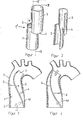
- the known heart valve prosthesis 1 ⁇ of the inventor shown in FIGS. 1 to 4 consists of two tube elements 2, 3, which are connected to one another in the axial direction and connected by a common wall 4.
- the first hose element 2 forms a first passage opening 5
- the second hose element 3 forms a second passage opening 6.
- this prosthesis is implanted, for example, as an aortic valve prosthesis in the ascending aorta, the first tube element 2 extending over the ostia of the coronary arteries, one of which is indicated at 40 in FIGS. 3 and 4.
- the second tube element 3 preferably bent in the longitudinal direction protrudes into the aortic arc.
- the implanted prosthesis is connected to the aortic wall 7 by support sutures 8, 9.
- the stroke volume of the left ventricle enters the first tube element 2 in the direction of the arrow and leaves it through the first passage opening 5.
- the common wall 4 of the tube elements 2, 3 is pivoted out of the flow path, so that the flow channel formed by the second hose element 3 and in particular its Passage 6 is closed.
- the diastolic phase (FIG. 4)
- the blood flows in the opposite direction, but this time through the flow channel which has returned to the open state at the end of the expulsion period and which the second tube element 3 forms, as the arrow in FIG. 4 indicates.
- the second tube element 3 expands and closes the passage opening 5 of the first tube element 2.
- the diastolic blood therefore does not flow to the ventricle, but rather through the second passage opening 6 to the ostium 40.
- the heart valve prosthesis 1 shown comprises a valve body 10 which is designed as a short, tube-like element.
- the outer shape of the valve body 10 is adapted to the aortic wall contour.
- An opening 16 is provided in the tube wall of the valve body 10 and, when the heart valve prosthesis 1 is implanted as an aortic valve prosthesis, lies opposite the ostium 40 of a coronary artery.
- a second corresponding opening can be provided opposite the ostium of the other coronary artery (not shown); instead of the opening 16 can also extend in the circumferential direction of the valve body 10 over both ostia.
- the wall area of the valve body 10 between the opening 16 and the ring area 14 merges in one piece in a connecting area 23 into a tongue 20, which is thereby connected at its one end area 22 to a peripheral partial area of the valve body 10.
- the material thickness of the tongue 20 decreases, starting from the end region 22 of the tongue 20 which merges into the connecting region 23 up to an essentially straight front edge 28 at the free end 24 of the tongue.
- the front edge 28 merges approximately at right angles into side edges 32 (only one shown) of the tongue 20, so that the tongue 20 is approximately rectangular overall.
- the inner circumferential wall of the valve body 10 forms a contact surface 18 against which the free end 24 of the tongue 20 can rest.
- the free end 24 of the tongue 20 is pivoted out of the direction of flow and lies in front of the opening 16.
- the systolic blood can therefore pass through a first Flow through opening 12, which is bounded by the proximal main surface of the tongue 20 and the inner peripheral wall of the valve body 10. An unwanted entry from systolic blood through the opening 16 into the ostium 40 is prevented by the tongue 20 closing the opening 16.
- the blood pressure direction reverses. Due to the elasticity of the tongue material, at the end of the systolic phase, the tongue 20 has been pivoted back from the position shown in FIG. 5 towards the first passage opening 12. If the diastolic blood flow now flows against it, the tongue 20, as illustrated in FIG. 6, closes over the first passage opening 12 and thereby seals the aorta in the ventricular direction, the free end 24 resting against the contact surface 18. The distal major surface of the tongue 20 directs the diastolic blood flow to the opening 16 so that it can enter the ostium of the respective coronary artery.
- the modification shown in FIGS. 7 and 8 of the embodiment just described has a fastening ring (annealing ring) 15 which surrounds the proximal end of the valve body 10.
- the fastening ring 15 is used analogously to the ring region 14 described above for the attachment of a support suture 30 which fixes the prosthesis to the aortic wall.
- the tongue 20 is fastened with an end region 22 to the inside of the proximal end of the valve body 10, for example by welding, gluing or the like.
- the contact surface 18 extends at This embodiment between the distal end of the valve body 10 and an inwardly projecting annular shoulder 19, which serves as a seat for the free end 24 of the tongue 20.
- the width of the tongue in the connection area 23 is so large that the tongue 20 can cover the opening 16 (or two separate openings 16) communicating with the ostia 40, 42.
- the tongue 20 can be fastened to the inner wall of the valve body 10 in addition to the opening 16, for example by welding, gluing or integral molding. This improves the covering function of the tongue 20 compared to the opening 16.
- the tongue 20 can also be designed such that its material thickness decreases from the longitudinal center to the side edges 32.
- FIGS. 9 and 10 illustrate the shape of the tongue 20 and in particular show the decrease in the material thickness in the direction of the front edge 28 and the side edges 32.
- these dimensions will be chosen depending on the material to be used so that a sufficiently large and easy mobility of the free end 24 of the tongue 20 on the one hand, but on the other hand a sufficient elastic restoring effect is obtained so that the tongue 20 moves quickly and completely under the blood pressure into the opening or blocking position, but not in at the point of reversal between systole and diastole the last position remains, but is brought back into a middle position, from which it can then move into the desired new position.
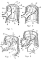
- FIG. 11 to 13 show a second embodiment of the heart valve prosthesis according to the invention. While in the first embodiment described above the tongue 20 is practically completely inside the valve body 10, in this second embodiment a tongue 60 is provided which is arranged at the distal end of a valve body 50.
- the valve body 50 is also a short, tube-like element in this embodiment. At the proximal (in FIGS. 11 and 12: lower) end, it carries a fastening ring 56 on the outside, by means of which the prosthesis can be sutured to the aortic wall 7 (FIG. 12). As with the first embodiment described with reference to FIGS. 5 to 10, this fastening ring 56 is, however, optional; the prosthesis can also be fixed directly to the aortic wall 7 without a ring area or fastening ring.
- the tongue 60 emerges in one piece from a peripheral partial region of the uninterrupted valve body wall. It has a free end which ends in a front edge 58 and can, with this free end, lie sealingly over the first passage opening which is formed by the distal opening of the valve body 50. As in the first embodiment, the material thickness of the tongue 60 decreases towards the front edge 58. Along the longitudinal center 62 of the tongue 60 there is an elevation 52 which can be formed in this area by a correspondingly larger material thickness. The elevation 52 becomes flatter and narrower in the direction of the front edge 58 in order not to impair the mobility of the free end of the tongue 60.
- the outer circumferential surface of the valve body 50 is provided with two channel-like depressions 54 which lead to the distal main surface of the tongue 60 facing away from the valve body 50 and each open onto this main side of the tongue 60 on one side of the elevation 52.
- the recesses 54 extend from the tongue 60 around the circumference of the valve body 50, as illustrated in FIGS. 11 and 12.
- this embodiment is implanted as an aortic valve prosthesis, as shown in FIG. 12, then the depressions 54 lead to the ostia of the coronary arteries; this is shown for an ostium 40 in FIG.
- Fig. 13 shows this position of the prosthesis as seen from the ventricle; the depressions 54 are not shown.
- the prostheses according to the invention are designed in such a way that they do not oppose the blood flow, in particular the systolic blood flow, with any sharp edges. This not only prevents turbulence, but also mechanical damage to blood cells.
- the prostheses according to the invention can be produced from suitable materials that are compatible as an implant and have the necessary mechanical properties.
- Polyurethane, polypropylene or polytetrafluor are suitable as biocompatible plastic materials ethylene (Teflon). Instead, it can also be considered to use suitable biomaterials, for example bovine pericardium.
- prosthesis according to the invention is not limited to use as an aortic valve prosthesis; rather, the prosthesis can also be used to replace organ parts other than the aortic valve, possibly with a corresponding modification in the structure.
- the prosthesis does not have to be designed so that the tongue lies substantially against the valve body in the blocking position;
- a system on the vessel wall (aortic wall) also fulfills the function sought according to the invention.
Abstract
Description
Die Erfindung betrifft eine Herzklappenprothese in Form eines Zweiwegeventils, mit einem im wesentlichen rohrartigen Ventilkörper, der mindestens eine erste Durchtrittsöffnung definiert, und einem mit diesem verbundenen Ventilelement, das unter dem Richtungswechsel des Blutdrucks zwischen einer die Durchtrittsöffnung verschließenden Sperrstellung und einer sie freigebenden Öffnungsstellung bewegbar ist und das Blut in der Sperrstellung zu einer zweiten Durchtrittsöffnung gelangen läßt.The invention relates to a heart valve prosthesis in the form of a two-way valve, with an essentially tubular valve body that defines at least one first passage opening, and a valve element connected to it, which can be moved under the change in direction of the blood pressure between a blocking position closing the passage opening and an opening position releasing it and allows the blood to reach a second passage opening in the blocking position.
Im Stand der Technik sind bereits Herzklappenpro thesen, insbesondere für die Aortenklappe, in vielfältigen Konstruktionsformen und Ausgestaltungen bekannt. Ältere Vorschläge waren auf die Verwendung von Ball- bzw. Deckelklappen-Ventilen als Herzklappenprothese gerichtet, führten jedoch wegen der zwangsläufig auftretenden Umströmungsvorgänge zu einer starken mechanischen Beanspruchung der Blutkörperchen, die deren Beschädigung bzw. Zerstörung fördert und damit die Gefahr von Koagulationen (Thromben) mit sich bringt.Heart valves are already in the prior art theses, especially for the aortic valve, are known in a variety of designs and configurations. Older proposals were directed to the use of ball or lid valve valves as a heart valve prosthesis, but due to the inevitable flow processes, the mechanical stress on the blood cells increases, which promotes their damage or destruction and thus the risk of coagulation (thrombi) brings itself.
Der Versuch, eine Herzklappenprothese unter Nachahmung der natürlichen Form von Segelklappen zu schaffen ("Medical and Biological Engineering", Juli 1975, Seiten 509 bis 517) scheitert an Mängeln in der Funktion und/oder Lebensdauer der Prothese.The attempt to create a heart valve prosthesis imitating the natural shape of sail valves ("Medical and Biological Engineering", July 1975, pages 509 to 517) fails because of defects in the function and / or service life of the prosthesis.
Deckelklappenprothesen sind beispielsweise aus der DE-PS 15 41 286 und der DE-PS 28 46 299 bekannt, führen aber zu der genannten starken mechanischen Beanspruchung der Blutkörperchen. Aus der DE-OS 27 00 531 ist eine, der natürlichen Aortenklappe nachgebildete Taschenklappe bekannt; diese hat jedoch einen so komplizierten Aufbau, daß sie den Anforderungen an Funktion und Lebensdauer einer Herzklappenprothese, insbesondere einer Aortenklappenprothese nicht gerecht wird.Lid flap prostheses are known, for example, from DE-PS 15 41 286 and DE-PS 28 46 299, but lead to the strong mechanical stress of the blood cells mentioned. From DE-OS 27 00 531 a pocket flap modeled after the natural aortic valve is known; However, this has such a complicated structure that it does not meet the requirements for the function and service life of a heart valve prosthesis, in particular an aortic valve prosthesis.
Der Erfinder der vorliegenden Anmeldung hat zur Überwindung der im Stand der Technik nicht gelösten Probleme eine Herzklappenprothese der eingangs genannten Art vorgeschlagen; diese ist in der DE-PS 34 26 300 offenbart. Aufbau und Funktion dieser bekannten Herzklappenprothese werden in der folgenden Figurenbeschreibung näher erläutert werden.The inventor of the present application has proposed a heart valve prosthesis of the type mentioned at the outset to overcome the problems not solved in the prior art; this is in the DE-PS 34 26 300 disclosed. The structure and function of this known heart valve prosthesis will be explained in more detail in the following description of the figures.
Obwohl diese Herzklappenprothese die mechanischen Störungen überwindet, an denen der vorgenannte Stand der Technik leidet, ist sie in einzelnen Aspekten noch zu verbessern. Die gattungsbildende Herzklappenprothese besteht aus zwei schlauchförmigen Kanalstücken, die jeweils einen Strömungskanal bilden und deren Wandungen (bzw. eine gemeinsame Wandung) so angeordnet und vom Blutdruck verformbar sind, daß sich der erste Kanal unter dem systolischen, der zweite Kanal unter dem diastolischen Druck im wesentlichen öffnet, während der jeweils andere Kanal geschlossen ist. Der Platzbedarf dieser bekannten Prothese, insbesondere hinsichtlich ihrer Längserstreckung, ist jedoch noch erheblich, was die Implantation erschwert. Außerdem muß zur Erzielung der gewünschten Ventilfunktion das distale schlauchförmige Kanalstück eine Schwenkbewegung durchführen, die unter Biegung der die Strömungskanäle verbindenden Wandung(en) erfolgt. Dies kann nur unter Überwindung von Trägheits- und elastischen Rückstellkräften geschehen, die die Ansprechzeiten der Prothese bei Richtungsumkehr des Blutdruckes relativ lang werden lassen.Although this heart valve prosthesis overcomes the mechanical disturbances from which the aforementioned prior art suffers, it can still be improved in individual aspects. The generic heart valve prosthesis consists of two tubular channel pieces, each of which forms a flow channel and whose walls (or a common wall) are arranged and deformable by blood pressure in such a way that the first channel is under the systolic, the second channel under the diastolic pressure essentially opens while the other channel is closed. However, the space required for this known prosthesis, particularly with regard to its longitudinal extent, is still considerable, which makes implantation more difficult. In addition, in order to achieve the desired valve function, the distal tubular channel piece has to perform a pivoting movement which takes place under bending of the wall (s) connecting the flow channels. This can only be done by overcoming inertia and elastic restoring forces, which make the response times of the prosthesis relatively long when the direction of the blood pressure changes.
Obwohl die Eigenbewegung dieser bekannten Herzklappenprothese gegenüber dem älteren Stand der Technik erheblich verringert ist und den Blutkörperchen nur wenig Prallfläche entgegengesetzt wird, was deren Zerstörung und Koagulation erheblich reduziert, ist die verbleibende Eigenbewegung der Herzklappenprothese daher noch unbefriedigend.Although the intrinsic movement of this known heart valve prosthesis is considerably reduced compared to the older state of the art and the blood cells have only a small baffle surface becomes, which considerably reduces their destruction and coagulation, the remaining self-movement of the heart valve prosthesis is therefore still unsatisfactory.
Die Aufgabe der Erfindung besteht vor diesem Hintergrund darin, eine Herzklappenprothese der eingangs genannten Art so zu verbessern, daß ohne Preisgabe der günstigen Durchströmungseigenschaften und langen Lebensdauer eine möglichst widerstandslose Ventilfunktion bei verringerter Gesamtlänge der Prothese ermöglicht wird.Against this background, the object of the invention is to improve a heart valve prosthesis of the type mentioned at the outset in such a way that a valve function which is as resistant as possible and with a reduced overall length of the prosthesis is made possible without giving up the favorable flow properties and long service life.
Erfindungsgemäß wird diese Aufgabe dadurch gelöst, daß das Ventilelement von einer flexiblen Zunge gebildet wird, die nur an ihrem einen Endbereich mit einem Umfangs-Teilbereich des Ventilkörpers verbunden ist.According to the invention, this object is achieved in that the valve element is formed by a flexible tongue which is only connected at one end region to a peripheral partial region of the valve body.
Die Erfindung löst sich von dem Grundkonzept des gattungsbildenden Standes der Technik, nämlich jeden Strömungskanal als schlauchförmiges Element auszubilden und das Öffnen und Schließen der Kanäle durch Verformung ihrer Wandung zu bewirken. Statt dessen wird gemäß der Erfindung ein einziger, rohrartiger Ventilkörper vorgesehen, der sehr kurz sein kann; die von dem Ventilkörper definierte erste Durchtrittsöffnung wird nicht mehr durch Wandungsverformung des Ventilkörpers, sondern durch eine flexible Zunge gesperrt bzw. freigegeben. Diese Zunge kann aus einem dünnen, kleinen Materialblättchen bestehen, so daß sie sehr viel leichter und schneller bewegt werden kann als der geschlossene, sehr viel größere Schlauch, der beim gattungsbil denden Stand der Technik den diastolisch durchflossenen Strömungskanal bildet.The invention separates from the basic concept of the generic state of the art, namely to design each flow channel as a tubular element and to open and close the channels by deforming their walls. Instead, according to the invention, a single, tubular valve body is provided, which can be very short; the first passage opening defined by the valve body is no longer blocked or released by wall deformation of the valve body, but by a flexible tongue. This tongue can consist of a thin, small sheet of material, so that it can be moved much more easily and quickly than the closed, much larger hose that the generic type the prior art forms the diastolic flow channel.
Natürlich muß auch bei der Erfindung der Blutstrom, den beim gattungsbildenden Stand der Technik der zweite Strömungskanal ableitet, gezielt zu seinem Bestimmungsort geführt werden. Diese Funktion übernimmt gemäß der Erfindung die Zunge, indem sie in ihrer Sperrstellung den Blutstrom zu der zweiten Durchtrittsöffnung gelangen läßt.Of course, in the case of the invention as well, the blood flow, which derives from the second flow channel in the generic state of the art, must be guided specifically to its destination. This function takes over the tongue according to the invention by allowing the blood flow to reach the second passage opening in its blocking position.
Die erfindungsgemäße Herzklappenprothese hat wenigstens die gleiche Lebensdauer wie die gattungsbildende Prothese. Sie setzt den Blutkörperchen nicht mehr Prallfläche entgegen, so daß die durch den gattungsbildenden Stand der Technik bereits erreichten Vorteile auch bei der Erfindung realisiert werden.The heart valve prosthesis according to the invention has at least the same lifespan as the generic prosthesis. It no longer opposes the blood cells to the baffle surface, so that the advantages already achieved by the generic state of the art are also realized in the invention.
Bevorzugte Ausführungsformen der Erfindung sind Gegenstand der Unteransprüche.Preferred embodiments of the invention are the subject of the dependent claims.
Nachstehend werden bevorzugte Ausführungsformen der Erfindung anhand der Zeichnung im einzelnen erläutert. Darin zeigt:
- Fig. 1 perspektivisch eine bekannte Prothese;
- Fig 2 einen Längsschnitt der Prothese gemäß Fig. 1 entlang der Linien II-II;
- Fig. 3 einen Längsschnitt durch die Aorta ascendens, den Arcus aortae und die imlantierte Prothese während der Systole;
- Fig. 4 einen Längsschnitt gemäß Fig. 3, jedoch während der Diastole;
- Fig. 5 einen Längsschnitt einer ersten Ausführungsform der Erfindung, implantiert in der Aorta ascendens, während der Systole;
- Fig. 6 einen Längsschnitt gemäß Fig. 5, während der Diastole;
- Fig. 7 einen Längsschnitt einer abgewandelten Prothese ähnlich Fig. 5, während der Systole;
- Fig. 8 einen Längsschnitt ähnlich Fig. 7, jedoch während der Diastole;
- Fig. 9 einen Teil der Prothese gemäß Fig. 5 und 6, einschließlich der Zunge;
- Fig. 10 den Teil gemäß Fig. 9, geschnitten entlang der Linie X-X;
- Fig. 11 eine zweite Ausführungsform der Prothese in teilweise geschnittener perspektivischer Ansicht;
- Fig. 12 die Prothese gemäß Fig. 11, implantiert in die Aorta ascendens und
- Fig. 13 eine schematische Ansicht der Prothese gemäß Fig. 11 und 12 in Blickrichtung durch den Ventilkörper auf die proximale Seite der Zunge.
- 1 shows a known prosthesis in perspective;
- 2 shows a longitudinal section of the prosthesis according to FIG. 1 along the lines II-II;
- Fig. 3 shows a longitudinal section through the aorta ascendens, the arcus aortae and the implanted prosthesis during systole;
- FIG. 4 shows a longitudinal section according to FIG. 3, but during the diastole;
- 5 shows a longitudinal section of a first embodiment of the invention, implanted in the ascending aorta, during systole;
- FIG. 6 shows a longitudinal section according to FIG. 5, during the diastole;
- FIG. 7 shows a longitudinal section of a modified prosthesis similar to FIG. 5 during systole;
- 8 shows a longitudinal section similar to FIG. 7, but during the diastole;
- 9 shows a part of the prosthesis according to FIGS. 5 and 6, including the tongue;
- 10 shows the part according to FIG. 9, cut along the line XX;
- 11 shows a second embodiment of the prosthesis in a partially sectioned perspective view;
- FIG. 12 shows the prosthesis according to FIG. 11, implanted in the ascending aorta and
- 13 shows a schematic view of the prosthesis according to FIGS. 11 and 12 in the direction of view through the valve body onto the proximal side of the tongue.
Die in Fig. 1 bis 4 gezeigte, bekannte Herzklappenprothese 1ʹ des Erfinders besteht aus zwei Schlauchelementen 2, 3, die in axialer Richtung gegeneinander verschoben durch eine gemeinsame Wandung 4 verbunden sind. Das erste Schlauchelement 2 bildet eine erste Durchtrittsöffnung 5, das zweite Schlauchelement 3 eine zweite Durchtrittsöffnung 6.The known heart valve prosthesis 1ʹ of the inventor shown in FIGS. 1 to 4 consists of two
Diese Prothese wird, wie Fig. 3 und 4 zeigen, beispielsweise als Aortenklappenprothese in die Aorta ascendens implantiert, wobei das erste Schlauchelement 2 sich über die Ostien der Koronararterien erstreckt, von denen eines in Fig. 3 und 4 bei 40 angedeutet ist. In dieser Stellung ragt das (vorzugsweise in Längsrichtung gebogene) zweite Schlauchelement 3 bis in den Arcus aortae vor.3 and 4, this prosthesis is implanted, for example, as an aortic valve prosthesis in the ascending aorta, the
Die implantierte Prothese wird durch Stütznähte 8, 9 mit der Aortenwand 7 verbunden.The implanted prosthesis is connected to the
In der Austreibungsphase gelangt das Schlagvolumen des linken Ventrikels in Pfeilrichtung in das erste Schlauchelement 2 und verläßt dieses durch die erste Durchtrittsöffnung 5. Unter dem systolischen Druck im Schlauchelement 2 wird die gemeinsame Wand 4 der Schlauchelemente 2, 3 aus der Strömungsbahn geschwenkt, so daß der vom zweiten Schlauchelement 3 gebildete Strömungskanal und insbesondere dessen Durchtrittsöffnung 6 geschlossen ist. Umgekehrt strömt das Blut in der diastolischen Phase (Fig. 4) in die entgegengesetzte Richtung, diesmal jedoch durch den am Ende der Austreibungsperiode in den geöffneten Zustand zurückgekehrten Strömungskanal, den das zweite Schlauchelement 3 bildet, wie der Pfeil in Fig. 4 andeutet. Dadurch erweitert sich das zweite Schlauchelement 3 und schließt die Durchtrittsöffnung 5 des ersten Schlauchelements 2. Das diastolische Blut strömt daher nicht zum Ventrikel, sondern vielmehr durch die zweite Durchtrittsöffnung 6 zum Ostium 40.In the expulsion phase, the stroke volume of the left ventricle enters the
Im folgenden wird nun die Erfindung an Beispielen von Aortenklappenprothesen erläutert.The invention will now be explained in the following using examples of aortic valve prostheses.
Fig. 5 und 6 zeigen eine erste Ausführungsform der Erfindung. Die gezeigte Herzklappenprothese 1 umfaßt einen Ventilkörper 10, der als kurzes, rohrstückartiges Element ausgebildet ist. Die äußere Form des Ventilkörpers 10 ist der Aortenwandkontur angepaßt.5 and 6 show a first embodiment of the invention. The
Am proximalen (in Fig. 5 und 6: unteren) Ende des Ventilkörpers 10 ist dieser zu einem Ringbereich 14 verdickt, der zur Befestigung der Prothese 1 an der Aortenwand 7 durch eine Stütznaht 30 dient.At the proximal (in FIGS. 5 and 6: lower) end of the
In der Rohrwandung des Ventilkörpers 10 ist eine Durchbrechung 16 vorgesehen, die bei Implantation der Herzklappenprothese 1 als Aortenklappenprothese dem Ostium 40 einer Koronararterie gegenüberliegt. Dem (nicht gezeigten) Ostium der anderen Koronararterie gegenüberliegend kann eine zweite entsprechende Durchbrechung vorgesehen sein; statt dessen kann die Durchbrechung 16 sich auch in Umfangsrichtung des Ventilkörpers 10 über beide Ostien erstrecken.An
Der Wandungsbereich des Ventilkörpers 10 zwischen der Durchbrechung 16 und dem Ringbereich 14 geht in einem Verbindungsbereich 23 einstückig in eine Zunge 20 über, die dadurch an ihrem einen Endbereich 22 mit einem Umfangs-Teilbereich des Ventilkörpers 10 verbunden ist. Die Materialdicke der Zunge 20 verringert sich, ausgehend vom in den Verbindungsbereich 23 übergehenden Endbereich 22 der Zunge 20 bis zu einer im wesentlichen geraden Vorderkante 28 am freien Ende 24 der Zunge. Die Vorderkante 28 geht etwa rechtwinklig in Seitenkanten 32 (nur eine gezeigt) der Zunge 20 über, so daß die Zunge 20 insgesamt etwa rechteckförmig ist.The wall area of the
An seinem distalen (in Fig. 5 und 6: oberen) Ende bildet die Innenumfangswand des Ventilkörpers 10 eine Anlagefläche 18, gegen die sich das freie Ende 24 der Zunge 20 anlegen kann.At its distal (in FIGS. 5 and 6: upper) end, the inner circumferential wall of the
Wenn zu Beginn der Systoledas Blut vom Ventrikel in die Prothese einströmt, wie der Pfeil in Fig. 5 andeutet, wird das freie Ende 24 der Zunge 20 aus der Strömungsrichtung geschwenkt und legt sich vor die Durchbrechung 16. Das systolische Blut kann daher durch eine erste Durchtrittsöffnung 12 strömen, die von der proximalen Hauptfläche der Zunge 20 und der Innenumfangswand des Ventilkörpers 10 begrenzt ist. Ein unerwünschter Eintritt von systolischem Blut durch die Durchbrechung 16 in das Ostium 40 wird dadurch verhindert, daß die Zunge 20 die Durchbrechung 16 verschließt.If, at the beginning of the systole, the blood flows into the prosthesis from the ventricle, as indicated by the arrow in FIG. 5, the
Zu Beginn der diastolischen Phase kehrt sich die Blutdruckrichtung um. Durch die Elastizität des Zungenmaterials ist am Ende der systolischen Phase die Zunge 20 von der in Fig. 5 gezeigten Stellung wieder in Richtung auf die erste Durchtrittsöffnung 12 zurückgeschwenkt worden. Wenn sie jetzt vom diastolischen Blutstrom angeströmt wird, legt sich die Zunge 20, wie Fig. 6 veranschaulicht, sperrend über die erste Durchtrittsöffnung 12 und dichtet die Aorta in Ventrikelrichtung dadurch ab, wobei sich das freie Ende 24 an die Anlagefläche 18 legt. Die distale Hauptfläche der Zunge 20 lenkt den diastolischen Blutstrom zur Durchbrechung 16, so daß er in das Ostium der jeweiligen Koronararterie eintreten kann.At the beginning of the diastolic phase, the blood pressure direction reverses. Due to the elasticity of the tongue material, at the end of the systolic phase, the
Die in Fig. 7 und 8 gezeigte Abwandlung der soeben beschriebenen Ausführungsform hat einen Befestigungsring (Annähring) 15, der das proximale Ende des Ventilkörpers 10 umschließt. Der Befestigungsring 15 dient analog dem oben beschriebenen Ringbereich 14 zur Anbringung einer Stütznaht 30, die die Prothese an der Aortenwand festlegt.The modification shown in FIGS. 7 and 8 of the embodiment just described has a fastening ring (annealing ring) 15 which surrounds the proximal end of the
Bei dieser Ausführungsform ist die Zunge 20 mit einem Endbereich 22 an der Innenseite des proximalen Endes des Ventilkörpers 10 befestigt, beispielsweise durch Schweißen, Kleben oder dergleichen. Die Anlagefläche 18 erstreckt sich bei dieser Ausführungsform zwischen dem distalen Ende des Ventilkörpers 10 und einer einwärts vorspringenden Ringschulter 19, die als Sitz für das freie Ende 24 der Zunge 20 dient.In this embodiment, the
Wie die Fig. 7 und 8 zeigen, ist die Öffnungs- und Schließfunktion der Zunge bei dieser Ausführungsform analog der oben anhand Fig. 5 und 6 beschriebenen.7 and 8 show, the opening and closing function of the tongue in this embodiment is analogous to that described above with reference to FIGS. 5 and 6.
Bei beiden Ausführungsformen ist die Breite der Zunge im Verbindungsbereich 23 so groß, daß die Zunge 20 die mit den Ostien 40, 42 kommunizierende Durchbrechung 16 (bzw. zwei separate solche Durchbrechungen 16) überdecken kann. An der Seitenkante 32 kann die Zunge 20 neben der Durchbrechung 16 an der Innenwand des Ventilkörpers 10 befestigt sein, beispielsweise durch Schweißen, Kleben oder einstückiges Anformen. Dies verbessert die Abdeckfunktion der Zunge 20 gegenüber der Durchbrechung 16. Neben der bereits genannten Abnahme der Materialdicke vom Verbindungsbereich 23 zur Vorderkante 28 hin kann die Zunge 20 auch so ausgebildet werden, daß ihre Materialdicke von der Längsmitte zu den Seitenkanten 32 hin abnimmt.In both embodiments, the width of the tongue in the
Die Fig. 9 und 10 veranschaulichen die Formgebung der Zunge 20 und zeigen insbesondere die Abnahme der Materialstärke in Richtung auf die Vorderkante 28 und die Seitenkanten 32. In der Praxis wird man diese Bemessungen je nach dem zu verwendenden Material so wählen, daß eine ausreichend große und leichte Beweglichkeit des freien Endes 24 der Zunge 20 einerseits, aber andererseits eine ausreichende elastische Rückstellwirkung erhalten wird, so daß sich die Zunge 20 unter dem Blutdruck schnell und vollständig in die Öffnungs- bzw. Sperrstellung bewegt, aber am Umkehrpunkt zwischen Systole und Diastole nicht in der zuletzt eingenommenen Stellung verharrt, sondern wieder in eine Mittelstellung gebracht wird, von der aus sie dann in die gewünschte neue Stellung treten kann.9 and 10 illustrate the shape of the
Fig. 11 bis 13 zeigen eine zweite Ausführungsform der erfindungsgemäßen Herzklappenprothese. Während bei der oben beschriebenen ersten Ausführungsform die Zunge 20 praktisch vollständig im Inneren des Ventilkörpers 10 liegt, ist bei dieser zweiten Ausführungsform eine Zunge 60 vorgesehen, die am distalen Ende eines Ventilkörpers 50 angeordnet ist.11 to 13 show a second embodiment of the heart valve prosthesis according to the invention. While in the first embodiment described above the
Der Ventilkörper 50 ist auch bei dieser Ausführungsform ein kurzes, rohrstückartiges Element. Er trägt am proximalen (in Fig. 11 und 12: unteren) Ende außenseitig einen Befestigungsring 56, mittels dessen die Prothese an der Aortenwand 7 angenäht werden kann (Fig. 12). Wie auch bei der anhand Fig. 5 bis 10 beschriebenen ersten Ausführungsform, ist dieser Befestigungsring 56 jedoch optional; die Prothese kann auch unmittelbar ohne Ringbereich bzw. Befestigungsring an der Aortenwand 7 festgelegt werden.The
Die Zunge 60 geht einstückig aus einem Umfangs-Teilbereich der nicht durchbrochenen Ventilkörperwandung hervor. Sie hat ein freies Ende, das in einer Vorderkante 58 endet, und kann sich mit diesem freien Ende dichtend über die erste Durchtrittsöffnung legen, die von der distalen Öffnung des Ventilkörpers 50 gebildet wird. Wie bei der ersten Ausführungsform wird die Materialdicke der Zunge 60 zur Vorderkante 58 hin geringer. Entlang der Längsmitte 62 der Zunge 60 verläuft eine Erhebung 52, die durch entsprechend größere Materialdicke in diesem Bereich gebildet werden kann. Die Erhebung 52 wird in Richtung auf die Vorderkante 58 hin flacher und schmaler, um die Beweglichkeit des freien Endes der Zunge 60 nicht zu beeinträchtigen.The
Die äußere Umfangsfläche des Ventilkörpers 50 ist mit zwei kanalartigen Vertiefungen 54 versehen, die zur distalen, vom Ventilkörper 50 abgewandten Hauptfläche der Zunge 60 führen und jeweils auf einer Seite der Erhebung 52 auf diese Hauptseite der Zunge 60 einmünden. Von der Zunge 60 weg erstrecken sich die Vertiefungen 54 um den Umfang des Ventilkörpers 50 herum, wie Fig. 11 und 12 veranschaulichen.The outer circumferential surface of the
Wird diese Ausführungsform als Aortenklappenprothese implantiert, wie Fig. 12 zeigt, dann führen die Vertiefungen 54 zu den Ostien der Koronararterien; in Fig. 12 ist dies für ein Ostium 40 dargestellt.If this embodiment is implanted as an aortic valve prosthesis, as shown in FIG. 12, then the
Während der Systole strömt Blut vom Ventrikel zur Prothese und tritt von deren proximaler Seite (in Fig. 12: von unten) in den Ventilkörper 50. Das durchtretende Blut schwenkt das freie Ende der Zunge 60 aus der Strömungsrichtung, wobei die Zunge 60 vom Ventilkörper 50 weggeschwenkt wird.During systole, blood flows from the ventricle to the prosthesis and enters the
Am Ende der systolischen Periode schwenkt das freie Ende der Zunge 60 durch die Materialelastizität zurück; bei Richtungsumkehr des Blutdrucks zu Beginn der diastolischen Periode legt sich die Zunge 60 über die Durchtrittsöffnung im Inneren des Ventilkörpers 50. Das anströmende Blut fließt über die distale Hauptfläche der Zunge 60 in die Vertiefungen 54 und gelangt so zu den Ostien. Fig. 13 zeigt diese Stellung der Prothese, gesehen vom Ventrikel aus; die Vertiefungen 54 sind nicht dargestellt.At the end of the systolic period, the free end of the
Die erfindungsgemäßen Prothesen werden so gestaltet, daß sie dem Blutstrom, insbesondere dem systolischen Blutstrom, keine scharfen Kanten entgegensetzen. Dadurch werden nicht nur Turbulenzen, sondern auch mechanische Beschädigungen von Blutkörperchen vermieden.The prostheses according to the invention are designed in such a way that they do not oppose the blood flow, in particular the systolic blood flow, with any sharp edges. This not only prevents turbulence, but also mechanical damage to blood cells.
Die erfindungsgemäßen Prothesen können aus geeigneten Materialien hergestellt werden, die als Implantat verträglich sind und die notwendigen mechanischen Eigenschaften aufweisen. Als biokompatible Kunststoffmaterialien eignen sich hierbei Polyurethan, Polypropylen oder Polytetrafluor ethylen (Teflon). Es kann statt dessen auch daran gedacht werden, geeignete Biomaterialien zu verwenden, beispielsweise Rinderperikard.The prostheses according to the invention can be produced from suitable materials that are compatible as an implant and have the necessary mechanical properties. Polyurethane, polypropylene or polytetrafluor are suitable as biocompatible plastic materials ethylene (Teflon). Instead, it can also be considered to use suitable biomaterials, for example bovine pericardium.
Die Anwendung der erfindungsgemäßen Prothese ist nicht auf den Einsatz als Aortenklappenprothese beschränkt; vielmehr läßt sich die Prothese, ggf. unter entsprechender Abwandlung im Aufbau, auch zum Ersatz anderer Organteile als der Aortenklappe verwenden.The use of the prosthesis according to the invention is not limited to use as an aortic valve prosthesis; rather, the prosthesis can also be used to replace organ parts other than the aortic valve, possibly with a corresponding modification in the structure.
Im Aufbau muß die Prothese nicht so ausgebildet werden, daß die Zunge in der Sperrstellung wesentlich am Ventilkörper anliegt; auch eine Anlage an der Gefäßwand (Aortenwand) erfüllt die erfindungsgemäß angestrebte Funktion.In construction, the prosthesis does not have to be designed so that the tongue lies substantially against the valve body in the blocking position; A system on the vessel wall (aortic wall) also fulfills the function sought according to the invention.
Claims (17)
dadurch gekennzeichnet, daß das Ventilelement von einer flexiblen Zunge (20, 60) gebildet wird, die nur an ihrem einen Endbereich (22) mit einem Umfangs-Teilbereich des Ventilkörpers (10, 50) verbunden ist.1. Heart valve prosthesis in the form of a two-way valve, with an essentially tubular valve body that defines at least a first passage opening, and a valve element connected to it, which is movable under the change in direction of the blood pressure between a blocking position closing the passage opening and an opening position releasing it, and that Allows blood to reach a second passage opening in the blocking position,
characterized in that the valve element is formed by a flexible tongue (20, 60) which is only connected at one end region (22) to a peripheral partial region of the valve body (10, 50).
dadurch gekennzeichnet, daß die Dicke der Zunge (20, 60) in Richtung auf ihr freies Ende (24) zu abnimmt.2. heart valve prosthesis according to claim 1,
characterized in that the thickness of the tongue (20, 60) decreases towards its free end (24).
dadurch gekennzeichnet, daß die Zunge (20, 60) nahe ihrer Längsmitte (62) dicker ist als an den Seitenkanten (32).3. heart valve prosthesis according to claim 1 or 2,
characterized in that the tongue (20, 60) is thicker near its longitudinal center (62) than at the side edges (32).
dadurch gekennzeichnet, daß die Zunge (20, 60) zum freien Ende (24) hin breiter wird.4. Heart valve prosthesis according to one of claims 1 to 3,
characterized in that the tongue (20, 60) widens towards the free end (24).
dadurch gekennzeichnet, daß die Zunge (20, 60) an ihrem mit dem Ventilkörper (10, 50) verbundenen Endbereich einstückig mit dem Ventilkörper (10, 50) ausgebildet ist.5. Heart valve prosthesis according to one of claims 1 to 4,
characterized in that the tongue (20, 60) is formed integrally with the valve body (10, 50) at its end region connected to the valve body (10, 50).
dadurch gekennzeichnet, daß die Zunge (20) am Ventilkörper (10) angeschweißt, angeklebt o.dgl. ist.6. Heart valve prosthesis according to one of claims 1 to 4,
characterized in that the tongue (20) is welded, glued or the like to the valve body (10). is.
dadurch gekennzeichnet, daß der Ventilkörper (10) als kurzes, rohrartiges Element ausgebildet ist und sich die Zunge (20) durch den vom Ventilkörper (10) umschlossenen Raum erstreckt.7. Heart valve prosthesis according to one of claims 1 to 6,
characterized in that the valve body (10) is designed as a short, tubular element and the tongue (20) extends through the space enclosed by the valve body (10).
dadurch gekennzeichnet, daß der Ventilkörper (10) eine Anlagefläche (18) für das freie Ende (24) der Zunge in deren Sperrstellung aufweist.8. heart valve prosthesis according to claim 7,
characterized in that the valve body (10) has a contact surface (18) for the free end (24) of the tongue in its locked position.
dadurch gekennzeichnet, daß der Ventilkörper (10) in seinem mit der Zunge (20) verbundenen Umfangs-Teilbereich wenigstens eine die zweite Durchtrittsöffnung bildende Durchbrechung (16) aufweist.9. heart valve prosthesis according to claim 7 or 8,
characterized in that the valve body (10) has at least one opening (16) forming the second passage opening in its peripheral partial area connected to the tongue (20).
dadurch gekennzeichnet, daß die Durchbrechung(en) (16) im als Aortenklappenprothese implantierten Zustand der Herzklappenprothese (1) einerseits mit den Ostien (4c, 42) der Koronararterien und andererseits mit der von der ersten Durchtrittsöffnung (12) abgewandten (distalen) Hauptfläche der Zunge (20) verbunden ist bzw. sind.10. heart valve prosthesis according to claim 9,
characterized in that the opening (s) (16) in the state of the heart valve prosthesis (1) implanted as an aortic valve prosthesis, on the one hand with the ostia (4c, 42) of the coronary arteries and on the other hand with the (distal) main surface of the tongue (20) facing away from the first passage opening (12) .
dadurch gekennzeichnet, daß der rohrstückartige Ventilkörper (10) in einem Verbindungsbereich (23), der sich entlang eines die Ostien (40, 42) beider Koronararterien einschließenden Teils der im Einbauzustand proximalen Umfangskante des Ventilkörpers (10) erstreckt, mit dem einen Endbereich (22) der Zunge (20) verbunden ist; daß der Ventilkörper (10) in distaler Richtung auf den Verbindungsbereich folgend wenigstens eine Durchbrechung (16) seiner Rohrwand zur Verbindung mit den Ostien aufweist und an seiner distalen Umfangskante wenigstens in dem Bereich, der nicht oberhalb der Durchbrechung (16) liegt, mit einer Anlagefläche (18) für das freie Ende (24) der Zunge (20) versehen ist, und daß sich die Zunge (20) von dem Verbindungsbereich (23) ausgehend aufwärts in den Innenraum des Ventilkörpers hineinerstreckt und ihre Länge so bemessen ist, daß eine Vorderkante (28) des freien Zungenendes (24) in der Sperrstellung im Bereich der Anlagefläche (18) liegt.11. Heart valve prosthesis according to claim 10,
characterized in that the tubular piece-like valve body (10) extends with the one end area (22.) in a connecting area (23) which extends along a part of the peripheral edge of the valve body (10) which is proximal in the installed state and which encloses the ostia (40, 42) of both coronary arteries ) the tongue (20) is connected; that the valve body (10) in the distal direction following the connection area has at least one opening (16) in its tube wall for connection to the ostia and on its distal peripheral edge at least in the area which is not above the opening (16) with a contact surface (18) is provided for the free end (24) of the tongue (20), and that the tongue (20) extends from the connecting area (23) upwards into the interior of the valve body and its length is such that a front edge (28) of the free tongue end (24) is in the locked position in the area of the contact surface (18).
dadurch gekennzeichnet, daß der Ventilkörper (50) als kurzes, rohrstückartiges Element ausgebildet ist und die Zunge (60) am im implantierten Zustand distalen Endbereich des Ventilkörpers (50) angeordnet ist.12. Heart valve prosthesis according to one of claims 1 to 6,
characterized in that the valve body (50) is designed as a short, tube-like element and the tongue (60) is arranged on the end region of the valve body (50) which is distal in the implanted state.
dadurch gekennzeichnet, daß die Zunge (60) auf ihrer vom Ventilkörper (50) abgewandten (distalen) Hauptfläche eine entlang ihrer Längsmitte (62) verlaufende Erhebung (52) aufweist, die vorzugsweise zum freien Ende der Zunge hin schmaler und flacher wird, und daß der Ventilkörper (50) in seiner Außenwand zwei kanalartige Vertiefungen (54) aufweist, die jeweils an einer Seite der Erhebung auf der distalen Zungenfläche einmünden und die zweite Durchtrittsöffnung bilden und sich jeweils wenigstens über einen Teil der Ventilkörper-Umfangsfläche, zur Verwendung als Aortenklappenprothese bis zu einem Koronararterien-Ostium (40 bzw. 42), erstrecken.13. Heart valve prosthesis according to claim 12,
characterized in that the tongue (60) on its (distal) main surface facing away from the valve body (50) has an elevation (52) running along its longitudinal center (62), which preferably becomes narrower and flatter towards the free end of the tongue, and that the valve body (50) has two channel-like depressions (54) in its outer wall, each opening on one side of the elevation on the distal tongue surface and forming the second passage opening and each extending over at least part of the valve body circumferential surface for use as an aortic valve prosthesis to a coronary artery ostium (40 or 42).
dadurch gekennzeichnet, daß die Zunge (20, 60) in der Öffnungsstellung die zweite Durchtrittsöffnung (16, 54) im wesentlichen sperrt.14. Heart valve prosthesis according to one of claims 1 to 13,
characterized in that the tongue (20, 60) essentially blocks the second passage opening (16, 54) in the open position.
dadurch gekennzeichnet, daß der Ventilkörper (10, 50), vorzugsweise proximal, einen verdickten Ringbereich (14) oder einen äußeren Befestigungsring (15, 56) (Annähring) aufweist.15. Heart valve prosthesis according to one of claims 1 to 14,
characterized in that the valve body (10, 50), preferably proximally, has a thickened ring area (14) or an outer fastening ring (15, 56) (annealing ring).
dadurch gekennzeichnet, daß der Ventilkörper (10, 50) in seiner Form der Aortenwand angepaßt ist und vorzugsweise seine vom Blut angeströmten Kanten gerundet sind.16. Heart valve prosthesis according to one of claims 1 to 15,
characterized in that the shape of the valve body (10, 50) is adapted to the aortic wall and preferably its edges against which the blood flows are rounded.
dadurch gekennzeichnet, daß die Herzklappenprothese (1) aus körperverträglichem Material, insbesondere biokompatiblem Kunststoff, besteht.17. Heart valve prosthesis according to one of claims 1 to 16,
characterized in that the heart valve prosthesis (1) consists of body-compatible material, in particular biocompatible plastic.
Applications Claiming Priority (2)
| Application Number | Priority Date | Filing Date | Title |
|---|---|---|---|
| US06/946,385 US4787901A (en) | 1984-07-17 | 1986-12-23 | Two-way acting valve and cardiac valve prosthesis |
| US946385 | 1986-12-23 |
Publications (1)
| Publication Number | Publication Date |
|---|---|
| EP0275535A1 true EP0275535A1 (en) | 1988-07-27 |
Family
ID=25484393
Family Applications (1)
| Application Number | Title | Priority Date | Filing Date |
|---|---|---|---|
| EP87119076A Withdrawn EP0275535A1 (en) | 1986-12-23 | 1987-12-22 | Heart valve prosthesis |
Country Status (1)
| Country | Link |
|---|---|
| EP (1) | EP0275535A1 (en) |
Cited By (9)
| Publication number | Priority date | Publication date | Assignee | Title |
|---|---|---|---|---|
| EP0515324A1 (en) * | 1991-05-24 | 1992-11-25 | SORIN BIOMEDICA CARDIO S.p.A. | A cardiac valve prosthesis, particularly for replacement of the aortic valve |
| WO1996029954A1 (en) * | 1995-03-28 | 1996-10-03 | Norman Godin | Prosthesis for preventing gastro-oesophageal reflux |
| US6126686A (en) * | 1996-12-10 | 2000-10-03 | Purdue Research Foundation | Artificial vascular valves |
| US6302917B1 (en) | 1998-08-31 | 2001-10-16 | Wilson-Cook Medical Incorporated | Anti-reflux esophageal prosthesis |
| US6746489B2 (en) | 1998-08-31 | 2004-06-08 | Wilson-Cook Medical Incorporated | Prosthesis having a sleeve valve |
| US8221505B2 (en) | 2007-02-22 | 2012-07-17 | Cook Medical Technologies Llc | Prosthesis having a sleeve valve |
| US9308360B2 (en) | 2007-08-23 | 2016-04-12 | Direct Flow Medical, Inc. | Translumenally implantable heart valve with formed in place support |
| US9445897B2 (en) | 2012-05-01 | 2016-09-20 | Direct Flow Medical, Inc. | Prosthetic implant delivery device with introducer catheter |
| US9603708B2 (en) | 2010-05-19 | 2017-03-28 | Dfm, Llc | Low crossing profile delivery catheter for cardiovascular prosthetic implant |
Citations (2)
| Publication number | Priority date | Publication date | Assignee | Title |
|---|---|---|---|---|
| DE3426300A1 (en) * | 1984-07-17 | 1986-01-30 | Doguhan Dr.med. 6000 Frankfurt Baykut | TWO-WAY VALVE AND ITS USE AS A HEART VALVE PROSTHESIS |
| EP0183904A2 (en) * | 1984-12-07 | 1986-06-11 | Shelhigh, Inc. | Prosthetic heart valve |
-
1987
- 1987-12-22 EP EP87119076A patent/EP0275535A1/en not_active Withdrawn
Patent Citations (2)
| Publication number | Priority date | Publication date | Assignee | Title |
|---|---|---|---|---|
| DE3426300A1 (en) * | 1984-07-17 | 1986-01-30 | Doguhan Dr.med. 6000 Frankfurt Baykut | TWO-WAY VALVE AND ITS USE AS A HEART VALVE PROSTHESIS |
| EP0183904A2 (en) * | 1984-12-07 | 1986-06-11 | Shelhigh, Inc. | Prosthetic heart valve |
Cited By (13)
| Publication number | Priority date | Publication date | Assignee | Title |
|---|---|---|---|---|
| EP0515324A1 (en) * | 1991-05-24 | 1992-11-25 | SORIN BIOMEDICA CARDIO S.p.A. | A cardiac valve prosthesis, particularly for replacement of the aortic valve |
| US5713953A (en) * | 1991-05-24 | 1998-02-03 | Sorin Biomedica Cardio S.P.A. | Cardiac valve prosthesis particularly for replacement of the aortic valve |
| WO1996029954A1 (en) * | 1995-03-28 | 1996-10-03 | Norman Godin | Prosthesis for preventing gastro-oesophageal reflux |
| US5861036A (en) * | 1995-03-28 | 1999-01-19 | Biomedix S.A. Switzerland | Medical prosthesis for preventing gastric reflux in the esophagus |
| US6126686A (en) * | 1996-12-10 | 2000-10-03 | Purdue Research Foundation | Artificial vascular valves |
| US6746489B2 (en) | 1998-08-31 | 2004-06-08 | Wilson-Cook Medical Incorporated | Prosthesis having a sleeve valve |
| US6302917B1 (en) | 1998-08-31 | 2001-10-16 | Wilson-Cook Medical Incorporated | Anti-reflux esophageal prosthesis |
| US8221505B2 (en) | 2007-02-22 | 2012-07-17 | Cook Medical Technologies Llc | Prosthesis having a sleeve valve |
| US9308360B2 (en) | 2007-08-23 | 2016-04-12 | Direct Flow Medical, Inc. | Translumenally implantable heart valve with formed in place support |
| US10130463B2 (en) | 2007-08-23 | 2018-11-20 | Dfm, Llc | Translumenally implantable heart valve with formed in place support |
| US9603708B2 (en) | 2010-05-19 | 2017-03-28 | Dfm, Llc | Low crossing profile delivery catheter for cardiovascular prosthetic implant |
| US10478299B2 (en) | 2010-05-19 | 2019-11-19 | Dfm, Llc | Low crossing profile delivery catheter for cardiovascular prosthetic implant |
| US9445897B2 (en) | 2012-05-01 | 2016-09-20 | Direct Flow Medical, Inc. | Prosthetic implant delivery device with introducer catheter |
Similar Documents
| Publication | Publication Date | Title |
|---|---|---|
| DE2815756C3 (en) | Prosthetic closure element to replace the valves in the human heart | |
| EP0143246B1 (en) | Heart valve prosthesis | |
| DE2742681C3 (en) | Prosthetic closure element to replace the mitral and tricus pldal valve in the human heart | |
| DE3426300A1 (en) | TWO-WAY VALVE AND ITS USE AS A HEART VALVE PROSTHESIS | |
| DE69721550T2 (en) | HEART VALVE PROSTHESIS WITH SEWING PART OF NON-SQUARE RADIAL WIDTH | |
| DE60017791T2 (en) | VESSEL VALVE FLAP | |
| DE3608435C2 (en) | ||
| DE2819089C2 (en) | ||
| DE3701702C1 (en) | Heart valve prosthesis | |
| DE60011132T2 (en) | PROSTHESIS FOR CHECKING THE FLOW DIRECTION IN A BODY VESSEL | |
| DE19509464C1 (en) | Implant for artery or vein, with anchor piece fixed to wall of vessel | |
| WO1997049355A1 (en) | Mitral valve prosthesis | |
| DE102007049404A1 (en) | Implant for placement in a blood circulation channel | |
| DE2440522A1 (en) | IMPLANT FOR ENABLING AN ADULT MAN TO GET PENIS ERECTIONS | |
| DE102017202159A1 (en) | Biological transcatheter flap | |
| EP2160156A1 (en) | Aortic sinus prosthesis | |
| WO2012065856A2 (en) | Stented biological heart valve | |
| EP0275535A1 (en) | Heart valve prosthesis | |
| EP0355323B1 (en) | Heart valve prosthesis | |
| DE10162821A1 (en) | Prosthetic vessel for aorta parts consists of flexible arch-shaped tube with pleating and fold with seams restricting tension and stitches through | |
| EP0920287B1 (en) | Diaphragm which can be implanted in the crystalline lens capsule of the eye | |
| DE3409005A1 (en) | PROSTHESIS FOR REPLACING AORTIC VALVES | |
| DE102017121143A1 (en) | Implantable valve prosthesis | |
| EP0910312B1 (en) | Cardiac valve prosthesis | |
| DE4204138C2 (en) | Heart valve prosthesis |
Legal Events
| Date | Code | Title | Description |
|---|---|---|---|
| PUAI | Public reference made under article 153(3) epc to a published international application that has entered the european phase |
Free format text: ORIGINAL CODE: 0009012 |
|
| AK | Designated contracting states |
Kind code of ref document: A1 Designated state(s): AT BE CH DE ES FR GB GR IT LI LU NL SE |
|
| 17P | Request for examination filed |
Effective date: 19890126 |
|
| 17Q | First examination report despatched |
Effective date: 19900921 |
|
| STAA | Information on the status of an ep patent application or granted ep patent |
Free format text: STATUS: THE APPLICATION IS DEEMED TO BE WITHDRAWN |
|
| 18D | Application deemed to be withdrawn |
Effective date: 19911203 |