EP0280234A2 - Method and apparatus for improving the treatment of fibre suspension and for the control of fibre suspension flow - Google Patents
Method and apparatus for improving the treatment of fibre suspension and for the control of fibre suspension flow Download PDFInfo
- Publication number
- EP0280234A2 EP0280234A2 EP88102569A EP88102569A EP0280234A2 EP 0280234 A2 EP0280234 A2 EP 0280234A2 EP 88102569 A EP88102569 A EP 88102569A EP 88102569 A EP88102569 A EP 88102569A EP 0280234 A2 EP0280234 A2 EP 0280234A2
- Authority
- EP
- European Patent Office
- Prior art keywords
- valve
- flow
- fibre suspension
- pulp
- opening
- Prior art date
- Legal status (The legal status is an assumption and is not a legal conclusion. Google has not performed a legal analysis and makes no representation as to the accuracy of the status listed.)
- Granted
Links
Images


Classifications
-
- D—TEXTILES; PAPER
- D21—PAPER-MAKING; PRODUCTION OF CELLULOSE
- D21C—PRODUCTION OF CELLULOSE BY REMOVING NON-CELLULOSE SUBSTANCES FROM CELLULOSE-CONTAINING MATERIALS; REGENERATION OF PULPING LIQUORS; APPARATUS THEREFOR
- D21C9/00—After-treatment of cellulose pulp, e.g. of wood pulp, or cotton linters ; Treatment of dilute or dewatered pulp or process improvement taking place after obtaining the raw cellulosic material and not provided for elsewhere
-
- B—PERFORMING OPERATIONS; TRANSPORTING
- B01—PHYSICAL OR CHEMICAL PROCESSES OR APPARATUS IN GENERAL
- B01F—MIXING, e.g. DISSOLVING, EMULSIFYING OR DISPERSING
- B01F23/00—Mixing according to the phases to be mixed, e.g. dispersing or emulsifying
- B01F23/50—Mixing liquids with solids
- B01F23/53—Mixing liquids with solids using driven stirrers
-
- B—PERFORMING OPERATIONS; TRANSPORTING
- B01—PHYSICAL OR CHEMICAL PROCESSES OR APPARATUS IN GENERAL
- B01F—MIXING, e.g. DISSOLVING, EMULSIFYING OR DISPERSING
- B01F25/00—Flow mixers; Mixers for falling materials, e.g. solid particles
- B01F25/30—Injector mixers
- B01F25/31—Injector mixers in conduits or tubes through which the main component flows
- B01F25/314—Injector mixers in conduits or tubes through which the main component flows wherein additional components are introduced at the circumference of the conduit
- B01F25/3141—Injector mixers in conduits or tubes through which the main component flows wherein additional components are introduced at the circumference of the conduit with additional mixing means other than injector mixers
-
- B—PERFORMING OPERATIONS; TRANSPORTING
- B01—PHYSICAL OR CHEMICAL PROCESSES OR APPARATUS IN GENERAL
- B01F—MIXING, e.g. DISSOLVING, EMULSIFYING OR DISPERSING
- B01F27/00—Mixers with rotary stirring devices in fixed receptacles; Kneaders
- B01F27/05—Stirrers
- B01F27/11—Stirrers characterised by the configuration of the stirrers
- B01F27/112—Stirrers characterised by the configuration of the stirrers with arms, paddles, vanes or blades
- B01F27/1126—Stirrers characterised by the configuration of the stirrers with arms, paddles, vanes or blades the stirrer being a bent rod supported at one end only
-
- B—PERFORMING OPERATIONS; TRANSPORTING
- B01—PHYSICAL OR CHEMICAL PROCESSES OR APPARATUS IN GENERAL
- B01F—MIXING, e.g. DISSOLVING, EMULSIFYING OR DISPERSING
- B01F27/00—Mixers with rotary stirring devices in fixed receptacles; Kneaders
- B01F27/50—Pipe mixers, i.e. mixers wherein the materials to be mixed flow continuously through pipes, e.g. column mixers
-
- B—PERFORMING OPERATIONS; TRANSPORTING
- B01—PHYSICAL OR CHEMICAL PROCESSES OR APPARATUS IN GENERAL
- B01F—MIXING, e.g. DISSOLVING, EMULSIFYING OR DISPERSING
- B01F27/00—Mixers with rotary stirring devices in fixed receptacles; Kneaders
- B01F27/05—Stirrers
- B01F27/11—Stirrers characterised by the configuration of the stirrers
- B01F27/112—Stirrers characterised by the configuration of the stirrers with arms, paddles, vanes or blades
- B01F27/1123—Stirrers characterised by the configuration of the stirrers with arms, paddles, vanes or blades sickle-shaped, i.e. curved in at least one direction
Definitions
- the present invention relates to a method and an apparatus for improving the control and treatment of fibre suspension flow.
- the method and apparatus according to the invention are particularly suitable to be used for mixing chemicals and controlling the pumping of high consistency pulp in the pulp and paper industry.
- High consistency pulp is still generally pumped by a displacement pump and a screw pump. This was up till now the only way to pump high consistency pulp.
- no control valve is used on the discharge side.
- high consistency pulp is stiff and the pumps produce a pulsational pressure. If there is a throttle point on the discharge side, it produces strong pressure pulses in the tube system which can break structures.
- a displacement pump works even when there is no pulp in the suction side or so little pulp that it would only partly fill the compartments of the pump. The pump can work so that it pumps forward everything that comes from the suction side to the compartments.
- High consistency pulp (consistency 8 - 20 %) forms very stiff material; it can be so stiff that one can stand with ordinary shoes on the pulp and not sink into the pulp.
- the reason for it is that fibres with size of a few millimetres form a strong three-dimensional fibre network.
- the fibres are rather rigid and when they rest on each other they form a strong structure.
- High consistency pulp can, however, be changed into a flowing state by breaking the fibre network by bringing shear forces to the suspension. This is called fluidization of high consistency pulp.
- Normally fluidization is effected by some kind of powerful rotor. For example, in a high consistency pump the rotor effects the fluidization in the suction duct of the pump. Fluidization is a reversible process, and as soon as the rotor stops or the pulp is no longer in the range of the rotor, the fibre network forms again and the suspension becomes again solid material.
- Fig. 6b shows in principle the reduction of the capacity of the present valves when the consistency grows.
- Fig. 6b is a graph showing the capacity of a valve provided with a fluidizator. The reliability of the valve and the adjustability improve particularly with small spread angles.
- a pump cannot be used as a mixer for several reasons. Such can be, for example, material problems or the fact that the amount or the quality of chemicals are such that the chemical cannot be added into the pump. Accordingly one has to use a separate mixer according to Fig. 2. There are cases in which part of the chemicals can be fed to the pump and the rest to the mixer or all chemicals to the mixer depending on the situation.
- the mixer consists of a case with an inlet opening and an outlet opening and protrusions on the inner surface, of a rotor which has protrusions on the outer surface, and of a feed duct for chemicals which opens to the mixing zone between the rotor and the case.
- the said mixer although very practical and reliable, is, however, rather complicated to produce of special material.
- a further object of the present invention is to eliminate the need of a separate mixer by means of a new kind of valve and to utilize the mixing properties of the valve as well as to lower the total resistance of the system and reduce the need of space.
- the FI-application 850307 discloses a method and an apparatus for dividing and uniting the flows of high-consistency fibre suspensions, wherein the apparatus consists of a vortex chamber to which several inlet and/or outlet openings lead and in which there is a rotor creating a vortex flow.
- the inventive idea of the present application includes also the fact that there are valves in the outlet ducts up to which the vortex flow should extend in order to make the apparatus work in the desired way.
- the object of the present invention is to eliminate or minimize the defects of the arrangements according to the above-mentioned publications by the method and apparatus in accordance with the invention.
- the above object is solved according to the invention by a method of controlling and treating a fibre suspension flow wherein the fibre suspension is controlled by throttling the cross-sectional area of the flow, characterized in that the fibre suspension is fluidized in that in close proximity to the throttle point, fibre suspension flow material is subjected to shear forces, by means of which the bonds between the fibres of the suspension are broken and the formation of fibre bundles at the throttle point is hindered, whereby the fibre suspension flows in a liquid state through the adjustable throttle point.
- an apparatus for controlling a fibre suspension flow which apparatus comprises a valve body having an inlet and outlet opening therein, a valve opening and a valve element with drive mechanism used for closing the opening, characterized in that in close proximity to the valve element a fluidizing element is arranged which acts to eliminate fibre net work and flocks of fibre suspension.
- the present invention is characterized in that the pulp is fluidized in the mixing valve i.e. the point of control to which pulp chemicals can be added.
- the valve is characterized in that it comprises a fluidizator and control plate or control ball.
- valve functions even at small spread angles evenly and without clogging, with no need for over spreading even at the starting point.
- valve mixer The valve and the mixer made of special materials are replaced by a valve mixer.
- FIG. 1 In the systems according to the prior art (Fig. 1) the aim has been to place the valve in a small pipe close to the discharge side of the pump. Thus a high flow rate is achieved at the valve, which makes the valve operate better and prevents the clogging.
- a valve according to the invention and the arrangement using it can be placed anywhere in the piping.
- valve The construction of the valve is such that it works regardless of the rate of inlet flow.
- the arrangement utilizing the invention enables mixing of chemicals without the pump being the only place where the they can be added. In many cases in bleaching processes, part of the chemicals can be added in the pump and the rest in the control valve. No separate mixer is needed. Thus the arrangement according to the prior art (Fig. 2) is essentially simplified.
- a significant advantage of the present invention resides in the great possibilities for adjustment of the volumetric flow. Because it is possible to fluidize the high consistency pulp just in front of the valve element, the valve opening can be throttled to its minimum and yet the pulp flow continues, in other words it is possible to reach low flow amounts even at high consistencies.
- Fig. 1a there is a so called principle of level control, in which the output of the pump 2 is adjusted by the valve 1 so that the level of the pulp in the pulp container 3 remains constant.
- Fig. 1b there is a so called principle of flow control, in which the pump 2 is attached to the pulp container 3 and thereafter there is a flow indicator 5 arranged in the flow passage through which a pulp flow passes, which flow is kept constant by the valve 6.
- the valve is disposed considerably far from the pump and in any case so far that high consistency pulp has time to form rigid fibre networks and the flow time to change into plug flow.
- the subsequent pressing of the pulp through the valve involves a great loss of pressure.
- a valve cannot be brought so near the pump to avoid the pulp having begun to solidify, because the formation of the fibre network begins already in the pump itself just after the fluidization zone of the pump.
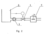
- Fig. 2 shows an arrangement according to the prior art, for example, for mixing bleaching chemicals to the suspension.
- the arrangement comprises a pulp tank 3, a pump 2, a level control valve 1 and a mixer 7 following the valve 1 in the direction of pulp flow, which mixer can be similar to, for example, the fluidizing mixer shown in the patent application FI 850854.
- Drawbacks of the arrangement are a considerable overall loss of pressure of the devices especially with high consistency pulps and the costs of devices made of special materials.
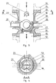
- a valve 10 comprises in general a valve body attached to pipe connections 11 and 12 or equivalents and inlet and outlet openings 14 and 15 in it.
- a valve opening 16 In the body 13 there is a valve opening 16 and the sealing surface thereof has a seat insert 17.
- the position of the calotte valve 19 is controlled by a control spindle 20 protruding from the the valve body 13.
- a coaxial shaft 21 protrudes from the valve body 13 in the opposite direction in relation to the spindle 20, and a fluidizing element 22 is attached to the head of shaft 21 inside the valve body 13 on the side of the coved surface of the calotte valve 19.
- the above described main components are preferably situated in the following way in relation to the direction of the pulp flow: firstly the fluidizing element 22, then the calotte valve 19, and then the valve opening 16.
- the valve in the opposite disposition with the fluidizing element behind the valve element in the direction of flow so as to hinder the fibres which might stick around the valve opening.
- the directions of the shafts of the rotor and the valve can differ from each other or one of the shafts can be within the other.
- the rotor can naturally also be arranged in connection with a shaft of another separate apparatus. For example, a screen, a thickener, a knotter or equivalent is appropriate.
- Fig. 3 and 4 also disclose a most preferable application field for the valve arrangement according to the invention.
- An inlet opening 23 for chemicals has been added to the valve body 13 in the direction of flow upstream of the other components and through which opening, for example, bleaching chemicals may be readily added into the pulp flow. Then by the same fluidization operation, by which the pulp is brought into a liquid form and as such flows through the valve, a very efficient mixing of the chemicals into the pulp is effected.
- the inlet opening for chemicals can also alternatively be located in the fluidization region.
- a valve element according to the invention functions in the following way.
- the pulp is subjected by the fluidizing element operating inside the valve body to such a considerable amount of shear forces that the bonds between the fibres forming a solid network of a pulp plug, loosen and the pulp flows like a fluid through the valve.
- the loss of pressure caused by the valve is consequently only a fraction of what it would be without fluidization.
- the most difficult situation is when the flow channel defined by the valve element 19 and the valve opening 16 is very small, in other words the volumetric flow is small.
- the fibres stick very easily on the fringes of the flow channel and gather forming in a short time a plug which closes the valve.
- the fluidizing element it causes a pulse at the flow channel against the normal direction of flow, in other words it tends to draw off the fibre bundles formed on the edge of the opening and to return them to the rest of the pulp. If a rotating rotor is involved, the fibre bundles can be loosened also by the total effect of the structure of the valve element and the rotational direction of the rotor.
- Fig. 5 discloses further preferred equipment arrangement, in which the valve 10 can also be used also as a mixer, if so required.
- a pump 2 is connected to a pulp tank 3 and the pump is followed by a valve apparatus 10 situated at an applicable place and, according to the embodiment in the figure is controlled by a level detector.
- the arrangement in Fig. 5 can well be compared to the arrangement in Fig. 2, because in both cases the same measures are involved: control of the pump and mixing of chemicals.
- the equipment in Fig. 5 is much simpler and an additional advantage is achieved by the higher outlet pressure compared to that of Fig. 2.
- the valve according to the invention can be employed, for example, in an apparatus in which pulp is led from the MC-pump to the thickener which requires a certain counter pressure to function in the desired way. Consequently, the consistency of the pulp flow being throttled can easily be more than 15 %, even 20 %, whereby to ensure the flow (in other words hindrance of the clogging of the throttle point) fluidization of pulp is required immediately before the valve.
- the valve is to be situated preferably exactly at the outlet opening of the thickener, because at the same time as the valve throttles the flow, it also enables the discharge of the pulp from the thickener.
- the valve can also be used in connection with other components treating high consistency pulp.
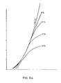
- Fig. 6a represents the behaviour of a conventional valve at high consistency pulps.
- the test consistencies were 8, 10, 13 and 15 %.
- the horizontal axis shows the spread angle of the valve and the vertical axis the mass flow passing through the valve.
- Fig. 6b represents correspondingly the behaviour of the valve according to the invention at high consistencies. It is seen in the same coordinates that at small spread angles the 15 % pulp does not differ from water, so the adjustability is as good as that of water. At larger spread angles the 15 % pulp requires a little larger spread angle than water, but the curve does not bend horizontal as occurred with the valves according to the prior art.
- Fig. 7 discloses comparative curves of the capacity (y-axis) of the valve in the function of the pressure difference prevailing across the valve.
- the curves show the Q pulp /Q water relation of the volumetric flows, which with the valves in accordance with the prior art (broken line curves) is already at the consistency of 10 % weak. In other words a big pressure difference is required for the efficiency of the flow to reach a profitable value. At the consistency of 15 % the pressure difference required is even bigger.
- unbroken curve a considerably better efficiency is achieved and the maximum value achieved with considerably smaller pressure difference is, less than half of the corresponding pressure difference of a valve in accordance with the prior art.
- valve and the fluidizing element are arranged in one and the same body, but, for example, for technical reasons in manufacture, it can be advantageous to construct the valve and the fluidizing element as separate components to be attached to each other. Furthermore, it is possible to reduce the pressure loss by arranging the form and function of the fluidizator and the valve element, in other words the rotational direction of the fluidizator, so that the pulp is subjected by the fluidizator to a kinetic component towards the valve opening.
- the material being used does not need to be high consistency pulp, but the mixing is applicable also to diluted pulps or mere fluids.
- the substances or chemicals to be mixed can be either gaseous, liquids or solids.
Abstract
Description
- The present invention relates to a method and an apparatus for improving the control and treatment of fibre suspension flow. The method and apparatus according to the invention are particularly suitable to be used for mixing chemicals and controlling the pumping of high consistency pulp in the pulp and paper industry.
- High consistency pulp is still generally pumped by a displacement pump and a screw pump. This was up till now the only way to pump high consistency pulp. When the pulp is pumped by such pumps, no control valve is used on the discharge side. There are two reasons for that. Firstly, high consistency pulp is stiff and the pumps produce a pulsational pressure. If there is a throttle point on the discharge side, it produces strong pressure pulses in the tube system which can break structures. Secondly, a displacement pump works even when there is no pulp in the suction side or so little pulp that it would only partly fill the compartments of the pump. The pump can work so that it pumps forward everything that comes from the suction side to the compartments.
- Lately a new type of high consistency pump has become general in the mills, cf. e.g. US-patent publication 4,435,122. This new kind of pump is a centrifugal pump, in which high consistency pulp is fluidized, in other words changed into a flowing state just before the pulp reaches the range of the pump impeller. With this technique in pumping high consistency pulp it is usually necessary to assemble a control valve on the discharge side of the pump according to Fig. 1 in order to ensure that there is always pulp in the suction side of the pump or that the amount of pulp to be pumped is correct.
- High consistency pulp (consistency 8 - 20 %) forms very stiff material; it can be so stiff that one can stand with ordinary shoes on the pulp and not sink into the pulp. The reason for it is that fibres with size of a few millimetres form a strong three-dimensional fibre network. The fibres are rather rigid and when they rest on each other they form a strong structure. High consistency pulp can, however, be changed into a flowing state by breaking the fibre network by bringing shear forces to the suspension. This is called fluidization of high consistency pulp. Normally fluidization is effected by some kind of powerful rotor. For example, in a high consistency pump the rotor effects the fluidization in the suction duct of the pump. Fluidization is a reversible process, and as soon as the rotor stops or the pulp is no longer in the range of the rotor, the fibre network forms again and the suspension becomes again solid material.
- If the capacity of a pump is adjusted by a control valve according to Fig. 1, the delivery lift is considerably lowered in the control valve because of the rigid character of the pulp. One object of the invention is to diminish the flow resistance of the valve. In controlling the flow of high consistency pulp the resistance is often several bars even on the best valves known. Fig. 6b shows in principle the reduction of the capacity of the present valves when the consistency grows.
- Fig. 6b is a graph showing the capacity of a valve provided with a fluidizator. The reliability of the valve and the adjustability improve particularly with small spread angles.
- In pulp mills it is often necessary to mix chemicals into the pulp for example in bleaching. This can be effected either in a high consistency pump or in a separate mixer, cf. FI application 850854. When chemicals are mixed in a high consistency pump, they are added either before the pump or at the outer rim of the impeller. If this is done, a separate mixer is not necessary, as the same device serves both as a mixer and a pump.
- Often a pump cannot be used as a mixer for several reasons. Such can be, for example, material problems or the fact that the amount or the quality of chemicals are such that the chemical cannot be added into the pump. Accordingly one has to use a separate mixer according to Fig. 2. There are cases in which part of the chemicals can be fed to the pump and the rest to the mixer or all chemicals to the mixer depending on the situation.
- This kind of mixer is described for example in FI-patent publication 68688. The mixer consists of a case with an inlet opening and an outlet opening and protrusions on the inner surface, of a rotor which has protrusions on the outer surface, and of a feed duct for chemicals which opens to the mixing zone between the rotor and the case. The said mixer, although very practical and reliable, is, however, rather complicated to produce of special material. A further object of the present invention is to eliminate the need of a separate mixer by means of a new kind of valve and to utilize the mixing properties of the valve as well as to lower the total resistance of the system and reduce the need of space.
- The FI-application 850307 discloses a method and an apparatus for dividing and uniting the flows of high-consistency fibre suspensions, wherein the apparatus consists of a vortex chamber to which several inlet and/or outlet openings lead and in which there is a rotor creating a vortex flow. The inventive idea of the present application includes also the fact that there are valves in the outlet ducts up to which the vortex flow should extend in order to make the apparatus work in the desired way. In the arrangement according to the above mentioned publication it has generally been necessary to position the control valves in the outlet ducts so far from the rotor that by the time the high consistency pulp reaches such it has formed a strong plug at the beginning of the duct in front of the valve opening and particularly with small spread angles.
- Summarizing the above, the object of the present invention is to eliminate or minimize the defects of the arrangements according to the above-mentioned publications by the method and apparatus in accordance with the invention.
- The above object is solved according to the invention by a method of controlling and treating a fibre suspension flow wherein the fibre suspension is controlled by throttling the cross-sectional area of the flow, characterized in that the fibre suspension is fluidized in that in close proximity to the throttle point, fibre suspension flow material is subjected to shear forces, by means of which the bonds between the fibres of the suspension are broken and the formation of fibre bundles at the throttle point is hindered, whereby the fibre suspension flows in a liquid state through the adjustable throttle point.
- The object is also solved by the provision of an apparatus for controlling a fibre suspension flow, which apparatus comprises a valve body having an inlet and outlet opening therein, a valve opening and a valve element with drive mechanism used for closing the opening, characterized in that in close proximity to the valve element a fluidizing element is arranged which acts to eliminate fibre net work and flocks of fibre suspension.
- The present invention is characterized in that the pulp is fluidized in the mixing valve i.e. the point of control to which pulp chemicals can be added. The valve is characterized in that it comprises a fluidizator and control plate or control ball.
- Further advantageous features of the invention are described in the dependent claims.
- Advantages of the present invention are discussed below with respect to the prior art.
- - The valve functions at high consistencies (15 - 25 %).
- - The valve functions even at small spread angles evenly and without clogging, with no need for over spreading even at the starting point.
- - The capacity of the valve remains almost the same as the water equivalent at lower pressure differences than those of the present pulp valves when adjusting pulp flows (cf. Fig. 7),

- - The valve and the mixer made of special materials are replaced by a valve mixer.
- - The total pressure loss is diminished.
- - It is possible to raise the consistency level of the mixture up to a consistency of 25 - 30 %. This is impossible with the known devices.
- In the systems according to the prior art (Fig. 1) the aim has been to place the valve in a small pipe close to the discharge side of the pump. Thus a high flow rate is achieved at the valve, which makes the valve operate better and prevents the clogging. A valve according to the invention and the arrangement using it can be placed anywhere in the piping.
- The construction of the valve is such that it works regardless of the rate of inlet flow.
- The arrangement utilizing the invention enables mixing of chemicals without the pump being the only place where the they can be added. In many cases in bleaching processes, part of the chemicals can be added in the pump and the rest in the control valve. No separate mixer is needed. Thus the arrangement according to the prior art (Fig. 2) is essentially simplified.
- A significant advantage of the present invention resides in the great possibilities for adjustment of the volumetric flow. Because it is possible to fluidize the high consistency pulp just in front of the valve element, the valve opening can be throttled to its minimum and yet the pulp flow continues, in other words it is possible to reach low flow amounts even at high consistencies.
- The apparatus according to the present invention is described in detail below, by way of example, with reference to the accompanying drawings, in which:
- Figs. 1a and 1b are schematic illustrations of prior art pumping arrangements.
- Fig. 2 is a schematic illustration of a mixing arrangement according to the prior art.
- Fig. 3 is a sectional side view of a preferred embodiment of an adjustable mixing valve according to the present invention.
- Fig. 4 is a fragmentary detail of a valve arrangement according to Fig. 3 from the incoming direction.
- Fig. 5 is a schematic illustration of a pumping arrangement including a adjustable mixing valve according to the present invention.
- Fig. 6a and 6b are graphs of flow-through curves of a valve according to the prior art and a valve according to the invention with pulps of different consistencies compared with the flow-through curves of water.
- Fig. 7 is a graph showing the comparison of corresponding valves in relation to the amount of pulp flow-through to the amount of water flowing through as a function of pressure difference prevailing across the valve.
- There are in principle two earlier known types of control arrangements of pulp pumping. In Fig. 1a there is a so called principle of level control, in which the output of the
pump 2 is adjusted by thevalve 1 so that the level of the pulp in thepulp container 3 remains constant. In Fig. 1b there is a so called principle of flow control, in which thepump 2 is attached to thepulp container 3 and thereafter there is aflow indicator 5 arranged in the flow passage through which a pulp flow passes, which flow is kept constant by thevalve 6. In both cases the valve is disposed considerably far from the pump and in any case so far that high consistency pulp has time to form rigid fibre networks and the flow time to change into plug flow. The subsequent pressing of the pulp through the valve involves a great loss of pressure. Additionally, it has to be noted that a valve cannot be brought so near the pump to avoid the pulp having begun to solidify, because the formation of the fibre network begins already in the pump itself just after the fluidization zone of the pump. - Fig. 2 shows an arrangement according to the prior art, for example, for mixing bleaching chemicals to the suspension. The arrangement comprises a
pulp tank 3, apump 2, alevel control valve 1 and amixer 7 following thevalve 1 in the direction of pulp flow, which mixer can be similar to, for example, the fluidizing mixer shown in the patent application FI 850854. Drawbacks of the arrangement are a considerable overall loss of pressure of the devices especially with high consistency pulps and the costs of devices made of special materials. - When aiming at a macroeconomic, compact and rational solution it has to be observed that in all pumping systems a valve subsequent to the pump is necessary so as to enable the function of the pump to be controlled in the desired way by means of the valve . Similarly, it has also to be observed that devices inadequate in operation even at the MC-consistencies diminish considerably the advantages obtainable by the MC-pumps. Thus one seeks an invention which minimizes the loss of pressure of the valve and ensures trouble-free operation. Fig. 3 and 4 disclose an arrangement in accordance with the invention in which a
valve 10 comprises in general a valve body attached topipe connections outlet openings body 13 there is avalve opening 16 and the sealing surface thereof has aseat insert 17. Together with theseat insert 17 there operates in the embodiment according to the figure, acalotte valve 19 with a V-opening 18, the inner and outer surface of which valve are a part of the spherical surface. The position of thecalotte valve 19 is controlled by acontrol spindle 20 protruding from the thevalve body 13. According to the figure acoaxial shaft 21 protrudes from thevalve body 13 in the opposite direction in relation to thespindle 20, and afluidizing element 22 is attached to the head ofshaft 21 inside thevalve body 13 on the side of the coved surface of thecalotte valve 19. The above described main components are preferably situated in the following way in relation to the direction of the pulp flow: firstly the fluidizingelement 22, then thecalotte valve 19, and then thevalve opening 16. It is, however, also possible to position the valve in the opposite disposition with the fluidizing element behind the valve element in the direction of flow so as to hinder the fibres which might stick around the valve opening. Similarly, the directions of the shafts of the rotor and the valve can differ from each other or one of the shafts can be within the other. The rotor can naturally also be arranged in connection with a shaft of another separate apparatus. For example, a screen, a thickener, a knotter or equivalent is appropriate. - Fig. 3 and 4 also disclose a most preferable application field for the valve arrangement according to the invention. An inlet opening 23 for chemicals has been added to the
valve body 13 in the direction of flow upstream of the other components and through which opening, for example, bleaching chemicals may be readily added into the pulp flow. Then by the same fluidization operation, by which the pulp is brought into a liquid form and as such flows through the valve, a very efficient mixing of the chemicals into the pulp is effected. Of course, the inlet opening for chemicals can also alternatively be located in the fluidization region. - A valve element according to the invention functions in the following way. With high consistency pulp, when the pulp flow coming from the pump reaches the valve as a plug flow, the pulp is subjected by the fluidizing element operating inside the valve body to such a considerable amount of shear forces that the bonds between the fibres forming a solid network of a pulp plug, loosen and the pulp flows like a fluid through the valve. The loss of pressure caused by the valve is consequently only a fraction of what it would be without fluidization. The most difficult situation is when the flow channel defined by the
valve element 19 and thevalve opening 16 is very small, in other words the volumetric flow is small. Hereby the fibres stick very easily on the fringes of the flow channel and gather forming in a short time a plug which closes the valve. It is, however, possible to design the fluidizing element so that it causes a pulse at the flow channel against the normal direction of flow, in other words it tends to draw off the fibre bundles formed on the edge of the opening and to return them to the rest of the pulp. If a rotating rotor is involved, the fibre bundles can be loosened also by the total effect of the structure of the valve element and the rotational direction of the rotor. - Fig. 5 discloses further preferred equipment arrangement, in which the
valve 10 can also be used also as a mixer, if so required. Apump 2 is connected to apulp tank 3 and the pump is followed by avalve apparatus 10 situated at an applicable place and, according to the embodiment in the figure is controlled by a level detector. The arrangement in Fig. 5 can well be compared to the arrangement in Fig. 2, because in both cases the same measures are involved: control of the pump and mixing of chemicals. The equipment in Fig. 5 is much simpler and an additional advantage is achieved by the higher outlet pressure compared to that of Fig. 2. - The valve according to the invention can be employed, for example, in an apparatus in which pulp is led from the MC-pump to the thickener which requires a certain counter pressure to function in the desired way. Consequently, the consistency of the pulp flow being throttled can easily be more than 15 %, even 20 %, whereby to ensure the flow (in other words hindrance of the clogging of the throttle point) fluidization of pulp is required immediately before the valve. Hereby the valve is to be situated preferably exactly at the outlet opening of the thickener, because at the same time as the valve throttles the flow, it also enables the discharge of the pulp from the thickener. Similarly, the valve can also be used in connection with other components treating high consistency pulp.
- Fig. 6a represents the behaviour of a conventional valve at high consistency pulps. The test consistencies were 8, 10, 13 and 15 %. The horizontal axis shows the spread angle of the valve and the vertical axis the mass flow passing through the valve. It will be appreciated from the graph that at a consistency of 10 % the flow rate of the pulp significantly begins to decrease at large spread angles and at a consistency of 15 % the value of the pulp flow remains below half of the maximum value which is achieved by water. Correspondingly, at small spread angles it is to be noted that a consistency of 15 % requires a spread angle at least double the size of that of water even to start the flow. Thus the control of small amounts of flow is by the conventional valves is most complicated, if not impossible.
- Fig. 6b represents correspondingly the behaviour of the valve according to the invention at high consistencies. It is seen in the same coordinates that at small spread angles the 15 % pulp does not differ from water, so the adjustability is as good as that of water. At larger spread angles the 15 % pulp requires a little larger spread angle than water, but the curve does not bend horizontal as occurred with the valves according to the prior art.
- Fig. 7 discloses comparative curves of the capacity (y-axis) of the valve in the function of the pressure difference prevailing across the valve. The curves show the Qpulp/Qwater relation of the volumetric flows, which with the valves in accordance with the prior art (broken line curves) is already at the consistency of 10 % weak. In other words a big pressure difference is required for the efficiency of the flow to reach a profitable value. At the consistency of 15 % the pressure difference required is even bigger. By the means of a valve according to the invention (unbroken curve) a considerably better efficiency is achieved and the maximum value achieved with considerably smaller pressure difference is, less than half of the corresponding pressure difference of a valve in accordance with the prior art.
- The above described arrangement according to the invention has thus made it possible to avoid or minimize the drawbacks and defects of the devices according to the prior art by simplifying the apparatus by combining applicable components to a rational entity. However, only a few specially preferable embodiments have been referred to above and such are not intended to limit the scope of the invention of what is disclosed in the enclosed claims. It is, for example, clear that it is not necessary to use a calotte valve with a V-opening but in some cases the use of a slide valve as well as a ball or a disc valve can be justified. Similarly, it is not necessary for the fluidizing element to be a rotor as in the figures, but also another kind of vibrator can be used. Neither is it necessary for the valve and the fluidizing element to be arranged in one and the same body, but, for example, for technical reasons in manufacture, it can be advantageous to construct the valve and the fluidizing element as separate components to be attached to each other. Furthermore, it is possible to reduce the pressure loss by arranging the form and function of the fluidizator and the valve element, in other words the rotational direction of the fluidizator, so that the pulp is subjected by the fluidizator to a kinetic component towards the valve opening.
- It is also clear that the material being used does not need to be high consistency pulp, but the mixing is applicable also to diluted pulps or mere fluids. Similarly, the substances or chemicals to be mixed can be either gaseous, liquids or solids.
Claims (11)
Priority Applications (1)
| Application Number | Priority Date | Filing Date | Title |
|---|---|---|---|
| EP93114759A EP0578284B1 (en) | 1987-02-23 | 1988-02-22 | Mixing apparatus for improving the treatment of fibre suspension |
Applications Claiming Priority (2)
| Application Number | Priority Date | Filing Date | Title |
|---|---|---|---|
| FI870747A FI82499C (en) | 1987-02-23 | 1987-02-23 | Device for improving regulation and treatment of fiber suspension flow |
| FI870747 | 1987-02-23 |
Related Child Applications (2)
| Application Number | Title | Priority Date | Filing Date |
|---|---|---|---|
| EP93114759A Division EP0578284B1 (en) | 1987-02-23 | 1988-02-22 | Mixing apparatus for improving the treatment of fibre suspension |
| EP93114759.9 Division-Into | 1993-09-14 |
Publications (3)
| Publication Number | Publication Date |
|---|---|
| EP0280234A2 true EP0280234A2 (en) | 1988-08-31 |
| EP0280234A3 EP0280234A3 (en) | 1991-01-09 |
| EP0280234B1 EP0280234B1 (en) | 1994-05-18 |
Family
ID=8523990
Family Applications (2)
| Application Number | Title | Priority Date | Filing Date |
|---|---|---|---|
| EP93114759A Expired - Lifetime EP0578284B1 (en) | 1987-02-23 | 1988-02-22 | Mixing apparatus for improving the treatment of fibre suspension |
| EP88102569A Expired - Lifetime EP0280234B1 (en) | 1987-02-23 | 1988-02-22 | Method and apparatus for improving the treatment of fibre suspension and for the control of fibre suspension flow |
Family Applications Before (1)
| Application Number | Title | Priority Date | Filing Date |
|---|---|---|---|
| EP93114759A Expired - Lifetime EP0578284B1 (en) | 1987-02-23 | 1988-02-22 | Mixing apparatus for improving the treatment of fibre suspension |
Country Status (7)
| Country | Link |
|---|---|
| EP (2) | EP0578284B1 (en) |
| JP (1) | JPS63288288A (en) |
| AT (2) | ATE185704T1 (en) |
| CA (1) | CA1313325C (en) |
| DE (3) | DE3856373T2 (en) |
| FI (1) | FI82499C (en) |
| NO (1) | NO178468B (en) |
Cited By (2)
| Publication number | Priority date | Publication date | Assignee | Title |
|---|---|---|---|---|
| US8177937B2 (en) | 2008-07-03 | 2012-05-15 | Metso Paper, Inc. | Method and an apparatus for controlling a flow of pulp suspension |
| WO2014068211A2 (en) | 2012-11-05 | 2014-05-08 | S.P.C.M. Sa | Device for injecting then mixing polymer in a pipe carrying a solid particle suspension, and method implementing the device |
Families Citing this family (1)
| Publication number | Priority date | Publication date | Assignee | Title |
|---|---|---|---|---|
| AT403063B (en) * | 1995-04-12 | 1997-11-25 | Andritz Patentverwaltung | DEVICE FOR MIXING CHEMICALS IN A FIBROUS SUSPENSION |
Citations (4)
| Publication number | Priority date | Publication date | Assignee | Title |
|---|---|---|---|---|
| DE1066544B (en) * | 1956-12-18 | 1959-10-08 | Aschaffenburger Zellstoffwerke | Device for mixing liquids with one another or with gases or mixtures of substances with different consistencies in a fixed, tubular housing with a rotating shaft |
| US4030969A (en) * | 1972-06-13 | 1977-06-21 | Defibrator Ab | Method of dispersing a bleaching agent into a stream of fibrous cellulosic pulp material in a throttling nozzle |
| DE3033240A1 (en) * | 1980-09-04 | 1982-04-01 | Wolfgang 4200 Oberhausen Riese | Silo vehicle discharge ball valve - has plug of segmental shape avoiding flow resistance and formation of dead spaces |
| US4662394A (en) * | 1985-10-25 | 1987-05-05 | Johnston Pump/General Valve, Inc. | Tight shut-off valve with flow control element |
Family Cites Families (3)
| Publication number | Priority date | Publication date | Assignee | Title |
|---|---|---|---|---|
| JPS6031554B2 (en) * | 1976-12-28 | 1985-07-23 | 日産自動車株式会社 | Coating method and equipment |
| US4199266A (en) * | 1977-08-31 | 1980-04-22 | Giusti Raolo B | Processing vessels |
| JPS6031554U (en) * | 1983-08-09 | 1985-03-04 | 株式会社 不二工機製作所 | valve |
-
1987
- 1987-02-23 FI FI870747A patent/FI82499C/en not_active IP Right Cessation
-
1988
- 1988-02-22 DE DE3856373T patent/DE3856373T2/en not_active Expired - Lifetime
- 1988-02-22 AT AT93114759T patent/ATE185704T1/en not_active IP Right Cessation
- 1988-02-22 EP EP93114759A patent/EP0578284B1/en not_active Expired - Lifetime
- 1988-02-22 CA CA000559428A patent/CA1313325C/en not_active Expired - Lifetime
- 1988-02-22 DE DE198888102569T patent/DE280234T1/en active Pending
- 1988-02-22 AT AT88102569T patent/ATE105884T1/en not_active IP Right Cessation
- 1988-02-22 DE DE3889559T patent/DE3889559T2/en not_active Expired - Lifetime
- 1988-02-22 NO NO880758A patent/NO178468B/en unknown
- 1988-02-22 EP EP88102569A patent/EP0280234B1/en not_active Expired - Lifetime
- 1988-02-23 JP JP63038762A patent/JPS63288288A/en active Granted
Patent Citations (4)
| Publication number | Priority date | Publication date | Assignee | Title |
|---|---|---|---|---|
| DE1066544B (en) * | 1956-12-18 | 1959-10-08 | Aschaffenburger Zellstoffwerke | Device for mixing liquids with one another or with gases or mixtures of substances with different consistencies in a fixed, tubular housing with a rotating shaft |
| US4030969A (en) * | 1972-06-13 | 1977-06-21 | Defibrator Ab | Method of dispersing a bleaching agent into a stream of fibrous cellulosic pulp material in a throttling nozzle |
| DE3033240A1 (en) * | 1980-09-04 | 1982-04-01 | Wolfgang 4200 Oberhausen Riese | Silo vehicle discharge ball valve - has plug of segmental shape avoiding flow resistance and formation of dead spaces |
| US4662394A (en) * | 1985-10-25 | 1987-05-05 | Johnston Pump/General Valve, Inc. | Tight shut-off valve with flow control element |
Cited By (4)
| Publication number | Priority date | Publication date | Assignee | Title |
|---|---|---|---|---|
| US8177937B2 (en) | 2008-07-03 | 2012-05-15 | Metso Paper, Inc. | Method and an apparatus for controlling a flow of pulp suspension |
| WO2014068211A2 (en) | 2012-11-05 | 2014-05-08 | S.P.C.M. Sa | Device for injecting then mixing polymer in a pipe carrying a solid particle suspension, and method implementing the device |
| FR2997635A1 (en) * | 2012-11-05 | 2014-05-09 | Spcm Sa | DEVICE FOR INJECTION THEN MIXING POLYMER IN A CANALIZATION TRANSPORTING SUSPENSION OF SOLID PARTICLES AND METHOD IMPLEMENTING THE DEVICE |
| WO2014068211A3 (en) * | 2012-11-05 | 2014-06-26 | S.P.C.M. Sa | Device for injecting then mixing polymer in a pipe carrying a solid particle suspension, and method implementing the device |
Also Published As
| Publication number | Publication date |
|---|---|
| FI82499C (en) | 1992-07-14 |
| NO880758L (en) | 1989-08-23 |
| NO880758D0 (en) | 1988-02-22 |
| NO178468B (en) | 1995-12-27 |
| DE3889559D1 (en) | 1994-06-23 |
| FI870747A (en) | 1988-08-24 |
| EP0578284A3 (en) | 1997-03-12 |
| FI82499B (en) | 1990-11-30 |
| DE3889559T2 (en) | 1994-09-29 |
| FI870747A0 (en) | 1987-02-23 |
| ATE185704T1 (en) | 1999-11-15 |
| EP0280234A3 (en) | 1991-01-09 |
| EP0578284A2 (en) | 1994-01-12 |
| DE280234T1 (en) | 1989-06-22 |
| JPH0240790B2 (en) | 1990-09-13 |
| CA1313325C (en) | 1993-02-02 |
| EP0578284B1 (en) | 1999-10-20 |
| JPS63288288A (en) | 1988-11-25 |
| DE3856373D1 (en) | 1999-11-25 |
| ATE105884T1 (en) | 1994-06-15 |
| EP0280234B1 (en) | 1994-05-18 |
| DE3856373T2 (en) | 2000-03-23 |
Similar Documents
| Publication | Publication Date | Title |
|---|---|---|
| CA2256387C (en) | A mixing or dissolving apparatus | |
| JP4871724B2 (en) | Method and apparatus for supplying chemicals to a liquid stream | |
| RU2013476C1 (en) | Method for pumping high-concentration fibrous suspension and apparatus for performing the same | |
| EP2622225B1 (en) | Centrifugal pump | |
| JP4310426B2 (en) | Gas mixing structure of pressurized centrifugal pump | |
| US5236285A (en) | High pressure feeder | |
| US5279709A (en) | Method and apparatus for improving the control and treatment of fiber suspension flow | |
| EP0280234A2 (en) | Method and apparatus for improving the treatment of fibre suspension and for the control of fibre suspension flow | |
| RU2079353C1 (en) | Method and device for mixing solid and liquid matters | |
| CA1316386C (en) | High-consistency pulp tower and method of discharging pulp from the tower | |
| FI102779B (en) | Apparatus and method for non-obstructing a liquid suspension flow | |
| CN113600088A (en) | Mixing system and mixing method | |
| JPS631506A (en) | Mixer | |
| US5690478A (en) | Solid material pump | |
| CN215963320U (en) | Mixing system | |
| EP0300251B1 (en) | Method and apparatus for pumping high consistency pulp | |
| EP1415094B1 (en) | Pulp pump | |
| DE19742500B4 (en) | Air-suction centrifugal pump with additional flow | |
| NO309011B1 (en) | Device for controlling a stream with a fiber suspension | |
| CN208415260U (en) | The pressing device of pulp shooting machine | |
| EP0233859A1 (en) | Self-priming centrifugal pump for handling liquids mixed with a high fiber content | |
| CN101432055B (en) | Method and device for shear-thinning of solids containing material | |
| FI129135B (en) | Wash nozzle assembly for atmospheric diffusers in pulp production | |
| RU2138158C1 (en) | Liquid homogenizing apparatus | |
| AT392216B (en) | Apparatus for separating gas |
Legal Events
| Date | Code | Title | Description |
|---|---|---|---|
| PUAI | Public reference made under article 153(3) epc to a published international application that has entered the european phase |
Free format text: ORIGINAL CODE: 0009012 |
|
| 17P | Request for examination filed |
Effective date: 19880222 |
|
| AK | Designated contracting states |
Kind code of ref document: A2 Designated state(s): AT DE FR GB IT SE |
|
| TCAT | At: translation of patent claims filed | ||
| EL | Fr: translation of claims filed | ||
| DET | De: translation of patent claims | ||
| RAP1 | Party data changed (applicant data changed or rights of an application transferred) |
Owner name: A. AHLSTROM CORPORATION |
|
| PUAL | Search report despatched |
Free format text: ORIGINAL CODE: 0009013 |
|
| AK | Designated contracting states |
Kind code of ref document: A3 Designated state(s): AT DE FR GB IT SE |
|
| 17Q | First examination report despatched |
Effective date: 19910830 |
|
| GRAA | (expected) grant |
Free format text: ORIGINAL CODE: 0009210 |
|
| AK | Designated contracting states |
Kind code of ref document: B1 Designated state(s): AT DE FR GB IT SE |
|
| PG25 | Lapsed in a contracting state [announced via postgrant information from national office to epo] |
Ref country code: IT Free format text: LAPSE BECAUSE OF FAILURE TO SUBMIT A TRANSLATION OF THE DESCRIPTION OR TO PAY THE FEE WITHIN THE PRE;WARNING: LAPSES OF ITALIAN PATENTS WITH EFFECTIVE DATE BEFORE 2007 MAY HAVE OCCURRED AT ANY TIME BEFORE 2007. THE CORRECT EFFECTIVE DATE MAY BE DIFFERENT FROM THE ONE RECORDED.SCRIBED TIME-LIMIT Effective date: 19940518 |
|
| REF | Corresponds to: |
Ref document number: 105884 Country of ref document: AT Date of ref document: 19940615 Kind code of ref document: T |
|
| REF | Corresponds to: |
Ref document number: 3889559 Country of ref document: DE Date of ref document: 19940623 |
|
| ET | Fr: translation filed | ||
| EAL | Se: european patent in force in sweden |
Ref document number: 88102569.6 |
|
| PLBE | No opposition filed within time limit |
Free format text: ORIGINAL CODE: 0009261 |
|
| STAA | Information on the status of an ep patent application or granted ep patent |
Free format text: STATUS: NO OPPOSITION FILED WITHIN TIME LIMIT |
|
| 26N | No opposition filed | ||
| REG | Reference to a national code |
Ref country code: GB Ref legal event code: 732E |
|
| REG | Reference to a national code |
Ref country code: FR Ref legal event code: TP |
|
| REG | Reference to a national code |
Ref country code: GB Ref legal event code: IF02 |
|
| PGFP | Annual fee paid to national office [announced via postgrant information from national office to epo] |
Ref country code: AT Payment date: 20070109 Year of fee payment: 20 |
|
| PGFP | Annual fee paid to national office [announced via postgrant information from national office to epo] |
Ref country code: GB Payment date: 20070115 Year of fee payment: 20 |
|
| PGFP | Annual fee paid to national office [announced via postgrant information from national office to epo] |
Ref country code: SE Payment date: 20070117 Year of fee payment: 20 |
|
| PGFP | Annual fee paid to national office [announced via postgrant information from national office to epo] |
Ref country code: DE Payment date: 20070118 Year of fee payment: 20 |
|
| REG | Reference to a national code |
Ref country code: GB Ref legal event code: PE20 |
|
| EUG | Se: european patent has lapsed | ||
| PGFP | Annual fee paid to national office [announced via postgrant information from national office to epo] |
Ref country code: FR Payment date: 20070111 Year of fee payment: 20 |
|
| PG25 | Lapsed in a contracting state [announced via postgrant information from national office to epo] |
Ref country code: GB Free format text: LAPSE BECAUSE OF EXPIRATION OF PROTECTION Effective date: 20080221 |