EP0280527A2 - Modular manual electric appliance - Google Patents
Modular manual electric appliance Download PDFInfo
- Publication number
- EP0280527A2 EP0280527A2 EP88301580A EP88301580A EP0280527A2 EP 0280527 A2 EP0280527 A2 EP 0280527A2 EP 88301580 A EP88301580 A EP 88301580A EP 88301580 A EP88301580 A EP 88301580A EP 0280527 A2 EP0280527 A2 EP 0280527A2
- Authority
- EP
- European Patent Office
- Prior art keywords
- appliance
- tubular portion
- module
- electric
- contacts
- Prior art date
- Legal status (The legal status is an assumption and is not a legal conclusion. Google has not performed a legal analysis and makes no representation as to the accuracy of the status listed.)
- Ceased
Links
Images

Classifications
-
- B—PERFORMING OPERATIONS; TRANSPORTING
- B25—HAND TOOLS; PORTABLE POWER-DRIVEN TOOLS; MANIPULATORS
- B25F—COMBINATION OR MULTI-PURPOSE TOOLS NOT OTHERWISE PROVIDED FOR; DETAILS OR COMPONENTS OF PORTABLE POWER-DRIVEN TOOLS NOT PARTICULARLY RELATED TO THE OPERATIONS PERFORMED AND NOT OTHERWISE PROVIDED FOR
- B25F5/00—Details or components of portable power-driven tools not particularly related to the operations performed and not otherwise provided for
- B25F5/02—Construction of casings, bodies or handles
- B25F5/021—Construction of casings, bodies or handles with guiding devices
-
- B—PERFORMING OPERATIONS; TRANSPORTING
- B25—HAND TOOLS; PORTABLE POWER-DRIVEN TOOLS; MANIPULATORS
- B25F—COMBINATION OR MULTI-PURPOSE TOOLS NOT OTHERWISE PROVIDED FOR; DETAILS OR COMPONENTS OF PORTABLE POWER-DRIVEN TOOLS NOT PARTICULARLY RELATED TO THE OPERATIONS PERFORMED AND NOT OTHERWISE PROVIDED FOR
- B25F3/00—Associations of tools for different working operations with one portable power-drive means; Adapters therefor
-
- B—PERFORMING OPERATIONS; TRANSPORTING
- B25—HAND TOOLS; PORTABLE POWER-DRIVEN TOOLS; MANIPULATORS
- B25F—COMBINATION OR MULTI-PURPOSE TOOLS NOT OTHERWISE PROVIDED FOR; DETAILS OR COMPONENTS OF PORTABLE POWER-DRIVEN TOOLS NOT PARTICULARLY RELATED TO THE OPERATIONS PERFORMED AND NOT OTHERWISE PROVIDED FOR
- B25F5/00—Details or components of portable power-driven tools not particularly related to the operations performed and not otherwise provided for
- B25F5/02—Construction of casings, bodies or handles
- B25F5/029—Construction of casings, bodies or handles with storage compartments
-
- H—ELECTRICITY
- H01—ELECTRIC ELEMENTS
- H01M—PROCESSES OR MEANS, e.g. BATTERIES, FOR THE DIRECT CONVERSION OF CHEMICAL ENERGY INTO ELECTRICAL ENERGY
- H01M50/00—Constructional details or processes of manufacture of the non-active parts of electrochemical cells other than fuel cells, e.g. hybrid cells
- H01M50/20—Mountings; Secondary casings or frames; Racks, modules or packs; Suspension devices; Shock absorbers; Transport or carrying devices; Holders
- H01M50/204—Racks, modules or packs for multiple batteries or multiple cells
- H01M50/207—Racks, modules or packs for multiple batteries or multiple cells characterised by their shape
- H01M50/213—Racks, modules or packs for multiple batteries or multiple cells characterised by their shape adapted for cells having curved cross-section, e.g. round or elliptic
-
- Y—GENERAL TAGGING OF NEW TECHNOLOGICAL DEVELOPMENTS; GENERAL TAGGING OF CROSS-SECTIONAL TECHNOLOGIES SPANNING OVER SEVERAL SECTIONS OF THE IPC; TECHNICAL SUBJECTS COVERED BY FORMER USPC CROSS-REFERENCE ART COLLECTIONS [XRACs] AND DIGESTS
- Y02—TECHNOLOGIES OR APPLICATIONS FOR MITIGATION OR ADAPTATION AGAINST CLIMATE CHANGE
- Y02E—REDUCTION OF GREENHOUSE GAS [GHG] EMISSIONS, RELATED TO ENERGY GENERATION, TRANSMISSION OR DISTRIBUTION
- Y02E60/00—Enabling technologies; Technologies with a potential or indirect contribution to GHG emissions mitigation
- Y02E60/10—Energy storage using batteries
Definitions
- the present invention relates to manual electric appliances such as electric drills for example.
- a variety of hand held electric tools are available, such as electric drills, electric screw drivers, electric socket wrenches and the like, and since such tools tend to be relatively bulky and heavy it is tiring and inconvenient to carry a set of different hand held electric tools around a site.
- the invention provides a hand held electric appliance comprising a handle portion and characterised by a generally tubular portion extending therefrom and carrying a plurality of power supply contacts on its interior, an electric appliance module being releasable mounted within such tubular portion and incorporating an electric appliance portion which is connected to further contacts located on the exterior of the appliance module, which further contacts engage said power supply contacts within said tubular portion.
- the appliance module carries a plurality of electric appliance portions and can be mounted within a tubular portion in a selected one of a plurality of orientations so as to expose a selected of said appliance portions and house another of said appliance portions according to the orientation selected.
- These appliance portions may be high-speed and rotary tools respectively and may be driven by a common electric motor located within their appliance module.
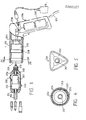
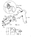
- the hand tools shown in Figure 1 comprises a handle portion 106 which is pivotally connected to a tubular portion 103, into which is releasably mounted an appliance module 202, in a manner which is described in detail with reference to Figure 3 below.
- Rechargeable nickel cadmium cells 1 and 2 are held within handle 106 by a screw - in cap 3.
- the pivotal connection between handle 106 and handle portion 103 is provided by a lug 104 which extends within a split portion and is held therein by a bolt 108 whose shank 107 passes through hole 105 and a nut 111 which screws onto the threaded portion of the bolt.
- the head of the bold fits within a hexagonal recess 102.
- the upper and lower surfaces of lug 104 are serrated and the inner surfaces of the split portion of tubular portion 103 are similarly serrated so that when the nut 111 and bolt 108 are tightened the engagements of the serrated surfaces locks the tubular portion 103 in a fixed orientation with respect to the handle 106.
- the split portions of the tubular portion 103 (which are resilient) can move apart slightly so that the angle between the handle 106 and tubular portion 103 can be adjusted.
- an electric appliance module 202 is shown withdrawn from the interior 203 of the tubular portion 103 which extends from handle portion 106.
- two annular contacts 208 are provided on the interior 203 and engage respective contacts 220 which in turn are connected to a motor 201 of module 202.
- Motor 201 is connected directly to a high speed output shaft 209 which carries a drill chuck 213 and is connected via a gear box 210 to a low speed output shaft 211 which carries a socket wrench 212.
- a connection with a power source which maybe either a mains lead 207 or a battery assembly 207 prime can be established by operating a switch 206. If a battery assembly 207 prime is employed as the power source a socket (unreferenced) maybe provided on the exterior of handle 106 to enable the batteries to be recharged from a plug (unreferenced) attached to a DC supply.
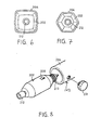
- casing 204 of tubular portion 103 is shown as having a circular cross-section in Figure 4, it may alternatively have a generally triangular configuration as shown in Figure 5, a generally rectangular configuration as shown in Figure 6 or a hexagonal configuration as shown in Figure 7.
- a screw 231 maybe provided as shown in Figure 8 which screws through the casing 204 of tubular portion 103 to engage module 202 and prevent it from rotating within tubular portion 103.
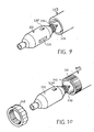
- FIG. 9 An alternative method of locking module 202 in position is shown in Figure 9 which shows grooves 236 in tubular portion 103 which engage projections 235 (only one of which is shown) in module 202 to prevent it rotating.
- FIG. 10 A further possible arrangement is shown in Figure 10 wherein diametrically opposed slots to 40 in the mouth of tubular portion 103 which enable the resulting split portions of this mouth to be forced together against the exterior of module 202 inserted therein when an undersized, preferably tapered ring nut 242 is screwed onto an exterior threaded portion of the mouth.
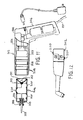
- FIG 11 shows a further embodiment in which module 202 carries a lamp bulb 312 in a holder 310 mounted on a reflector 311 at one thereof and a soldering iron 303 in a heat-proof holder 306 at its opposite end.
- the soldering iron is provided with a heating element 305 wound on an insulting member 304 and connected to the upper and bottom left hand pair (as shown in Figure 11) of three contacts 220 on the exterior of the module.
- the lamp bulb 312 is connected between the upper contact 220 and lower right hand contact 220 (as shown).
- Figure 12 shows an alternative module which can be used in the embodiment of Figure 11. This comprises a miniature vacuum cleaner whose motor is provided with contacts 220.
- Module 202A carries a lamp bulb 312 mounted in a holder 310 on a reflector 311 at one end thereof and carries a soldering iron 303 mounted in a heat-proof casing 303 at the other end thereof.
- the element 305 of the soldering is connected to a lower and an upper lift contact 220 (as shown in Figure 13) where as bulb 311 is connected to the lower and an upper right contact 220 (as shown).
- the upper left and lower contacts 220 engage contact 208 prime and energise the soldering iron.
- the lower module 202B incorporates a motor 201 which in connected to just two contacts 220 which accordingly engage contacts 208 when this module is inserted irrespective of whether a low speed shaft 211 carrying socket wrench 212 is exposed or the high speed output shaft 209 carrying drill chuck 213 is exposed.
- the motor 201 is connected directly to the high speed output shafts 209 and is connected via a step down gear box 210 to the low speed output shafts 211.
- a variety of screw-driver and other rotary tools can be fitted within socket wrench 212 as shown in Figure 13; such tools are conveniently in a rear compartment of the handle portion as shown in Figure 14A.
- An on/off switch 206 is provided and a reversing switch 1156 is also provided to enable the direction of rotation of the output shafts of motor 201 to be reversed.
- the circuit diagram is shown in Figure 15.
- Figures 16,17 and 18 show various non-circular configurations of the modules 202A and 202B which may be fitted within correspondingly shaped tubular portions 103 of similarly non-circular configuration.
- the modules 202A and 202B are non-circular in cross-section, it is not necessary to provide any screw locking means as shown in Figure 8 to prevent them from rotating. However, it may be desirable to provide some releasable gripping means to prevent them from being withdrawn inadvertently from tubular portion 103.
- a variety of electric tools may be provided in modular form for insertion into tubular portion 103, such as electric brushes, electric shaping and grinding tools, electric polishing tools and the like.
- the embodiment of Figures 13 to 15 has the advantage that the two exposed appliance portions such as the lamp bulb 312 and drill chuck 213 (when the modules shown in Figure 13 are reversed in orientation before insertion) may cooperate.
- the lamp bulb 312 may be arranged to illuminate the area of a hole drilled by a drill held in drill chuck 213.
- the invention provides a hand held electric tool in which the angle between the a handle portion and a body portion thereof may be adjusted.
Abstract
Description
- The present invention relates to manual electric appliances such as electric drills for example.
- A variety of hand held electric tools are available, such as electric drills, electric screw drivers, electric socket wrenches and the like, and since such tools tend to be relatively bulky and heavy it is tiring and inconvenient to carry a set of different hand held electric tools around a site.
- In order to overcome this problem, the invention provides a hand held electric appliance comprising a handle portion and characterised by a generally tubular portion extending therefrom and carrying a plurality of power supply contacts on its interior, an electric appliance module being releasable mounted within such tubular portion and incorporating an electric appliance portion which is connected to further contacts located on the exterior of the appliance module, which further contacts engage said power supply contacts within said tubular portion.
- This enables a kit containing one handle portion with its tubular extension and a plurality of electric appliance modules to replace a set of conventional hand held electric appliances. When a different function is required, the electric appliance module within the tubular portion maybe replaced by the user with an appropriate different module.
- In a preferred embodiment of the invention, the appliance module carries a plurality of electric appliance portions and can be mounted within a tubular portion in a selected one of a plurality of orientations so as to expose a selected of said appliance portions and house another of said appliance portions according to the orientation selected.
- These appliance portions may be high-speed and rotary tools respectively and may be driven by a common electric motor located within their appliance module.
- Further advantageous preferred features are defined in the dependent claims.
- Preferred embodiments of the invention are described below by way of example only with reference to Figures 1 to 18 of the accompanying drawings, of which:
- Figure 1 is an elevation, partly in section of hand held electric tool in accordance with the invention;
- Figure 2 is an exploded perspective view showing the connection between the handle and tubular portion of the tool of Figure 1;
- Figure 3 is an elevation, partly in section showing a further embodiment of the invention;
- Figure 4 is a section taken on IV - IV of Figure 3;
- Figure 5 is an end elevation showing an alternative configuration of the
module 202; - Figure 6 shows a further possible configuration of
module 202; - Figure 7 shows a further possible configuration of
module 202; - Figure 8 is a perspective view showing a method of
fixing module 202 withintubular portion 103; - Figure 9 is perspective view showing an alternative method of fixing module within
tubular portion 103; - Figure 10 is perspective view showing a further possible method of
fixing module 202 withintubular portion 103; - Figure 11 is a side elevation of further embodiment of the invention;
- Figure 12 shows a further module which maybe used in electric appliances in accordance with the invention;
- Figure 14 is a perspective view of a further embodiment of the invention;
- Figure 15 is a wiring diagram of the embodiment of the embodiment of Figure 14;
- Figure 13 is a side elevation, partly in section of the embodiment of Figure 14;
- Figure 16 is an end elevation showing a variant of the embodiment of Figures 13 to 15;
- Figure 17 is an end elevation showing a further variant of this embodiment,
- Figure 18 is an end elevation showing yet another variant of this embodiment.
- The hand tools shown in Figure 1 comprises a
handle portion 106 which is pivotally connected to atubular portion 103, into which is releasably mounted anappliance module 202, in a manner which is described in detail with reference to Figure 3 below. Rechargeable nickel cadmium cells 1 and 2 are held withinhandle 106 by a screw - in cap 3. The pivotal connection betweenhandle 106 andhandle portion 103 is provided by a lug 104 which extends within a split portion and is held therein by a bolt 108 whoseshank 107 passes through hole 105 and a nut 111 which screws onto the threaded portion of the bolt. The head of the bold fits within a hexagonal recess 102. The upper and lower surfaces of lug 104 are serrated and the inner surfaces of the split portion oftubular portion 103 are similarly serrated so that when the nut 111 and bolt 108 are tightened the engagements of the serrated surfaces locks thetubular portion 103 in a fixed orientation with respect to thehandle 106. By unscrewing the nut 111 the split portions of the tubular portion 103 (which are resilient) can move apart slightly so that the angle between thehandle 106 andtubular portion 103 can be adjusted. - Referring to Figures 3 and 4, an
electric appliance module 202 is shown withdrawn from theinterior 203 of thetubular portion 103 which extends fromhandle portion 106. As seen in Figures 3 and 4, twoannular contacts 208 are provided on theinterior 203 and engagerespective contacts 220 which in turn are connected to amotor 201 ofmodule 202. Motor 201 is connected directly to a highspeed output shaft 209 which carries adrill chuck 213 and is connected via agear box 210 to a lowspeed output shaft 211 which carries asocket wrench 212. When themodule 202 is inserted in tubular portion 103 a connection with a power source which maybe either amains lead 207 or abattery assembly 207 prime can be established by operating aswitch 206. If abattery assembly 207 prime is employed as the power source a socket (unreferenced) maybe provided on the exterior ofhandle 106 to enable the batteries to be recharged from a plug (unreferenced) attached to a DC supply. - Although the
casing 204 oftubular portion 103 is shown as having a circular cross-section in Figure 4, it may alternatively have a generally triangular configuration as shown in Figure 5, a generally rectangular configuration as shown in Figure 6 or a hexagonal configuration as shown in Figure 7. - If a circular configuration is employed, a
screw 231 maybe provided as shown in Figure 8 which screws through thecasing 204 oftubular portion 103 to engagemodule 202 and prevent it from rotating withintubular portion 103. - An alternative method of
locking module 202 in position is shown in Figure 9 which showsgrooves 236 intubular portion 103 which engage projections 235 (only one of which is shown) inmodule 202 to prevent it rotating. - A further possible arrangement is shown in Figure 10 wherein diametrically opposed slots to 40 in the mouth of
tubular portion 103 which enable the resulting split portions of this mouth to be forced together against the exterior ofmodule 202 inserted therein when an undersized, preferablytapered ring nut 242 is screwed onto an exterior threaded portion of the mouth. - Figure 11 shows a further embodiment in which
module 202 carries alamp bulb 312 in aholder 310 mounted on areflector 311 at one thereof and a solderingiron 303 in a heat-proof holder 306 at its opposite end. The soldering iron is provided with aheating element 305 wound on aninsulting member 304 and connected to the upper and bottom left hand pair (as shown in Figure 11) of threecontacts 220 on the exterior of the module. Thelamp bulb 312 is connected between theupper contact 220 and lower right hand contact 220 (as shown). When themodule 202 is inserted intotubular portion 103 in the orientation shown, only theupper contact 220 and the bottomleft hand contact 220 engage therespective contacts 208 so that only the soldering iron is energised on activatingswitch 206. If however themodule 202 is rotated 180° clockwise or anticlockwise before being inserted intotubular portion 103, only the contacts connected tolamp bulb 312 engagecontacts 208 so that only the lamp bulb is energised. - Figure 12 shows an alternative module which can be used in the embodiment of Figure 11. This comprises a miniature vacuum cleaner whose motor is provided with
contacts 220. - The embodiment shown in Figures 13,14 and 15 incorporates two appliance modules 202A and 202B which fit into upper and
lower parts tubular portion 103 respectively. Module 202A carries alamp bulb 312 mounted in aholder 310 on areflector 311 at one end thereof and carries a solderingiron 303 mounted in a heat-proof casing 303 at the other end thereof. Theelement 305 of the soldering is connected to a lower and an upper lift contact 220 (as shown in Figure 13) where asbulb 311 is connected to the lower and an upper right contact 220 (as shown). Accordingly, when module 202A is inserted in the orientation shown in Figures 13 and 14, the upper left andlower contacts 220 engagecontact 208 prime and energise the soldering iron. Alternatively, if this module is inserted in the reverse orientation, only the contacts connected tolamp bulb 312 are energised. The lower module 202B incorporates amotor 201 which in connected to just twocontacts 220 which accordingly engagecontacts 208 when this module is inserted irrespective of whether alow speed shaft 211 carryingsocket wrench 212 is exposed or the highspeed output shaft 209 carryingdrill chuck 213 is exposed. Themotor 201 is connected directly to the highspeed output shafts 209 and is connected via a step downgear box 210 to the lowspeed output shafts 211. A variety of screw-driver and other rotary tools can be fitted withinsocket wrench 212 as shown in Figure 13;
such tools are conveniently in a rear compartment of the handle portion as shown in Figure 14A. - An on/off
switch 206 is provided and areversing switch 1156 is also provided to enable the direction of rotation of the output shafts ofmotor 201 to be reversed. The circuit diagram is shown in Figure 15. - Figures 16,17 and 18 show various non-circular configurations of the modules 202A and 202B which may be fitted within correspondingly shaped
tubular portions 103 of similarly non-circular configuration. - It will be appreciated that since the modules 202A and 202B are non-circular in cross-section, it is not necessary to provide any screw locking means as shown in Figure 8 to prevent them from rotating. However, it may be desirable to provide some releasable gripping means to prevent them from being withdrawn inadvertently from
tubular portion 103. A variety of electric tools may be provided in modular form for insertion intotubular portion 103, such as electric brushes, electric shaping and grinding tools, electric polishing tools and the like. The embodiment of Figures 13 to 15 has the advantage that the two exposed appliance portions such as thelamp bulb 312 and drill chuck 213 (when the modules shown in Figure 13 are reversed in orientation before insertion) may cooperate. Thus thelamp bulb 312 may be arranged to illuminate the area of a hole drilled by a drill held indrill chuck 213. - The feature of the adjustable locking of the angle between the
handle portion 106 and theother portion 103 as disclosed in Figures 1 and 2 is a separate feature of the invention and is not necessarily limited to the features of claim 1. Thus in another aspect, the invention provides a hand held electric tool in which the angle between the a handle portion and a body portion thereof may be adjusted.
Claims (10)
Applications Claiming Priority (4)
| Application Number | Priority Date | Filing Date | Title |
|---|---|---|---|
| GB878704265A GB8704265D0 (en) | 1987-02-24 | 1987-02-24 | Manual electric tools(1) |
| GB8704265 | 1987-02-24 | ||
| GB8727118 | 1987-11-19 | ||
| GB8727118A GB2212428A (en) | 1987-11-19 | 1987-11-19 | Multi-function portable tool |
Publications (2)
| Publication Number | Publication Date |
|---|---|
| EP0280527A2 true EP0280527A2 (en) | 1988-08-31 |
| EP0280527A3 EP0280527A3 (en) | 1990-06-13 |
Family
ID=26291938
Family Applications (1)
| Application Number | Title | Priority Date | Filing Date |
|---|---|---|---|
| EP88301580A Ceased EP0280527A3 (en) | 1987-02-24 | 1988-02-24 | Modular manual electric appliance |
Country Status (1)
| Country | Link |
|---|---|
| EP (1) | EP0280527A3 (en) |
Cited By (21)
| Publication number | Priority date | Publication date | Assignee | Title |
|---|---|---|---|---|
| US4901438A (en) * | 1988-12-22 | 1990-02-20 | Gibney Brian E | Shielded cable cutting device |
| WO1994011162A1 (en) * | 1992-11-06 | 1994-05-26 | Emerson International Limited | A power tool |
| GB2317844A (en) * | 1996-10-07 | 1998-04-08 | William Strom | Winch drive |
| WO1999039877A1 (en) * | 1998-02-03 | 1999-08-12 | Atlas Copco Tools Ab | Portable power tool with separate pistol-type handle |
| US6102134A (en) * | 1998-10-16 | 2000-08-15 | Black & Decker Inc. | Two-position screwdriver |
| EP1293306A2 (en) * | 2001-08-27 | 2003-03-19 | Techtronic Industries Co., Ltd. | Portable electric tool |
| EP1314518A1 (en) | 2001-11-20 | 2003-05-28 | Black & Decker Inc. | A power tool having a handle and a pivotal tool body |
| FR2895928A1 (en) * | 2006-01-06 | 2007-07-13 | Georges Renault Soc Par Action | Gun type screwing and unscrewing tool e.g. unscrewer-screw gun, for rotating unit, has push buttons activated along longitudinal axis direction connecting front and rear parts of body of tool and mounted on shoulder provided on case of tool |
| US7414337B2 (en) * | 2005-03-14 | 2008-08-19 | Black & Decker Inc. | Scrubber |
| CN103203707A (en) * | 2012-01-13 | 2013-07-17 | 苏州宝时得电动工具有限公司 | Power tool and operation method for same |
| CN103252756A (en) * | 2012-01-13 | 2013-08-21 | 苏州宝时得电动工具有限公司 | Power tool |
| EP2687338A1 (en) * | 2012-07-19 | 2014-01-22 | Black & Decker Inc. | Lighted Power Tool |
| US8820955B2 (en) | 2009-02-25 | 2014-09-02 | Black & Decker Inc. | Power tool with light emitting assembly |
| US8827483B2 (en) | 2009-02-25 | 2014-09-09 | Black & Decker Inc. | Light for a power tool and method of illuminating a workpiece |
| US9028088B2 (en) | 2010-09-30 | 2015-05-12 | Black & Decker Inc. | Lighted power tool |
| US9242355B2 (en) | 2012-04-17 | 2016-01-26 | Black & Decker Inc. | Illuminated power tool |
| US9352458B2 (en) | 2009-02-25 | 2016-05-31 | Black & Decker Inc. | Power tool with light for illuminating workpiece |
| CN110450102A (en) * | 2019-08-20 | 2019-11-15 | 徐州莱益精密机械有限公司 | A kind of provision for disengagement of precision machinery |
| WO2021035902A1 (en) * | 2019-08-27 | 2021-03-04 | 蓝宙(江苏)技术有限公司 | Modular electric screwdriver toy |
| DE102010025586B4 (en) * | 2009-07-01 | 2021-04-15 | Johnson Electric International AG | Power tool |
| WO2022001744A1 (en) * | 2020-07-03 | 2022-01-06 | 南京德朔实业有限公司 | Electric tool |
Families Citing this family (1)
| Publication number | Priority date | Publication date | Assignee | Title |
|---|---|---|---|---|
| US7937792B2 (en) | 2006-10-19 | 2011-05-10 | Black & Decker Inc. | Pole scrubber |
Citations (12)
| Publication number | Priority date | Publication date | Assignee | Title |
|---|---|---|---|---|
| BE643674A (en) * | ||||
| CH127752A (en) * | 1927-10-22 | 1928-09-17 | Ernst Hug | Brush. |
| GB397185A (en) * | 1932-02-20 | 1933-08-21 | Duss & Bender Spezialfabrik Fu | Improvements in or relating to electrically driven hand tools |
| GB499725A (en) * | 1937-06-16 | 1939-01-27 | Bosch Gmbh Robert | Improvements in or relating to hand guided electrically driven implements |
| DE863933C (en) * | 1951-01-10 | 1953-01-22 | Otto Heins | Connection piece for tools with the corresponding handle |
| FR1368851A (en) * | 1963-06-24 | 1964-08-07 | Illuminating tool machine | |
| FR1547687A (en) * | 1966-10-20 | 1968-11-29 | Interelectric Ag | Portable device of an electric drive motor |
| DE1563646A1 (en) * | 1966-11-07 | 1970-04-23 | Raukamp & Co | Power delivery device for small motorized devices and lights |
| FR2282324A1 (en) * | 1974-08-23 | 1976-03-19 | Black & Decker Mfg Co | ELECTRICAL TOOL CONSISTING OF ASSEMBLED AND INTERCHANGEABLE MODULAR ELEMENTS AND CONTAINING ITS OWN POWER SOURCE |
| JPS59129607A (en) * | 1983-01-13 | 1984-07-26 | Youshirou Sugai | Electric drill attached with plug socket |
| EP0149777A2 (en) * | 1983-12-23 | 1985-07-31 | Firma Robert Schröder | Screwing-drilling device |
| EP0199241A2 (en) * | 1985-04-24 | 1986-10-29 | Newford Company Limited | Combined set of household electrical appliances and a handgrip therefor |
-
1988
- 1988-02-24 EP EP88301580A patent/EP0280527A3/en not_active Ceased
Patent Citations (12)
| Publication number | Priority date | Publication date | Assignee | Title |
|---|---|---|---|---|
| BE643674A (en) * | ||||
| CH127752A (en) * | 1927-10-22 | 1928-09-17 | Ernst Hug | Brush. |
| GB397185A (en) * | 1932-02-20 | 1933-08-21 | Duss & Bender Spezialfabrik Fu | Improvements in or relating to electrically driven hand tools |
| GB499725A (en) * | 1937-06-16 | 1939-01-27 | Bosch Gmbh Robert | Improvements in or relating to hand guided electrically driven implements |
| DE863933C (en) * | 1951-01-10 | 1953-01-22 | Otto Heins | Connection piece for tools with the corresponding handle |
| FR1368851A (en) * | 1963-06-24 | 1964-08-07 | Illuminating tool machine | |
| FR1547687A (en) * | 1966-10-20 | 1968-11-29 | Interelectric Ag | Portable device of an electric drive motor |
| DE1563646A1 (en) * | 1966-11-07 | 1970-04-23 | Raukamp & Co | Power delivery device for small motorized devices and lights |
| FR2282324A1 (en) * | 1974-08-23 | 1976-03-19 | Black & Decker Mfg Co | ELECTRICAL TOOL CONSISTING OF ASSEMBLED AND INTERCHANGEABLE MODULAR ELEMENTS AND CONTAINING ITS OWN POWER SOURCE |
| JPS59129607A (en) * | 1983-01-13 | 1984-07-26 | Youshirou Sugai | Electric drill attached with plug socket |
| EP0149777A2 (en) * | 1983-12-23 | 1985-07-31 | Firma Robert Schröder | Screwing-drilling device |
| EP0199241A2 (en) * | 1985-04-24 | 1986-10-29 | Newford Company Limited | Combined set of household electrical appliances and a handgrip therefor |
Non-Patent Citations (1)
| Title |
|---|
| PATENT ABSTRACTS OF JAPAN, vol. 8, no. 258 (M-340)[1695], 27th November 1984; & JP-A-59 129 607 (SUGAI) * |
Cited By (35)
| Publication number | Priority date | Publication date | Assignee | Title |
|---|---|---|---|---|
| US4901438A (en) * | 1988-12-22 | 1990-02-20 | Gibney Brian E | Shielded cable cutting device |
| WO1994011162A1 (en) * | 1992-11-06 | 1994-05-26 | Emerson International Limited | A power tool |
| GB2317844A (en) * | 1996-10-07 | 1998-04-08 | William Strom | Winch drive |
| GB2317844B (en) * | 1996-10-07 | 2001-04-11 | William Strom | Winch drive |
| US6250607B1 (en) | 1996-10-07 | 2001-06-26 | William Strom | Self tailing power winch drive |
| WO1999039877A1 (en) * | 1998-02-03 | 1999-08-12 | Atlas Copco Tools Ab | Portable power tool with separate pistol-type handle |
| US6527060B1 (en) | 1998-02-03 | 2003-03-04 | Atlas Copco Tools Ab | Portable power tool with separate pistol-type handle |
| US6102134A (en) * | 1998-10-16 | 2000-08-15 | Black & Decker Inc. | Two-position screwdriver |
| US6321856B1 (en) | 1998-10-16 | 2001-11-27 | Black & Decker Inc. | Two-position screwdriver |
| EP1293306A2 (en) * | 2001-08-27 | 2003-03-19 | Techtronic Industries Co., Ltd. | Portable electric tool |
| EP1293306A3 (en) * | 2001-08-27 | 2003-04-23 | Techtronic Industries Co., Ltd. | Portable electric tool |
| AU2002302087B2 (en) * | 2001-11-20 | 2007-06-14 | Black And Decker, Inc. | A power tool having a handle and a pivotal tool body |
| EP1314518A1 (en) | 2001-11-20 | 2003-05-28 | Black & Decker Inc. | A power tool having a handle and a pivotal tool body |
| US7414337B2 (en) * | 2005-03-14 | 2008-08-19 | Black & Decker Inc. | Scrubber |
| US7818864B2 (en) | 2005-03-14 | 2010-10-26 | Black & Decker Inc. | Scrubber |
| FR2895928A1 (en) * | 2006-01-06 | 2007-07-13 | Georges Renault Soc Par Action | Gun type screwing and unscrewing tool e.g. unscrewer-screw gun, for rotating unit, has push buttons activated along longitudinal axis direction connecting front and rear parts of body of tool and mounted on shoulder provided on case of tool |
| US8820955B2 (en) | 2009-02-25 | 2014-09-02 | Black & Decker Inc. | Power tool with light emitting assembly |
| US9352458B2 (en) | 2009-02-25 | 2016-05-31 | Black & Decker Inc. | Power tool with light for illuminating workpiece |
| US8827483B2 (en) | 2009-02-25 | 2014-09-09 | Black & Decker Inc. | Light for a power tool and method of illuminating a workpiece |
| DE102010025586B4 (en) * | 2009-07-01 | 2021-04-15 | Johnson Electric International AG | Power tool |
| US9328915B2 (en) | 2010-09-30 | 2016-05-03 | Black & Decker Inc. | Lighted power tool |
| US10543588B2 (en) | 2010-09-30 | 2020-01-28 | Black & Decker Inc. | Lighted power tool |
| US9644837B2 (en) | 2010-09-30 | 2017-05-09 | Black & Decker Inc. | Lighted power tool |
| US9028088B2 (en) | 2010-09-30 | 2015-05-12 | Black & Decker Inc. | Lighted power tool |
| US11090786B2 (en) | 2010-09-30 | 2021-08-17 | Black & Decker Inc. | Lighted power tool |
| CN103203707A (en) * | 2012-01-13 | 2013-07-17 | 苏州宝时得电动工具有限公司 | Power tool and operation method for same |
| CN103252756B (en) * | 2012-01-13 | 2015-04-22 | 苏州宝时得电动工具有限公司 | Power tool |
| CN103203707B (en) * | 2012-01-13 | 2015-03-11 | 苏州宝时得电动工具有限公司 | Power tool and operation method for same |
| CN103252756A (en) * | 2012-01-13 | 2013-08-21 | 苏州宝时得电动工具有限公司 | Power tool |
| US9242355B2 (en) | 2012-04-17 | 2016-01-26 | Black & Decker Inc. | Illuminated power tool |
| US10173307B2 (en) | 2012-04-17 | 2019-01-08 | Black & Decker Inc. | Illuminated power tool |
| EP2687338A1 (en) * | 2012-07-19 | 2014-01-22 | Black & Decker Inc. | Lighted Power Tool |
| CN110450102A (en) * | 2019-08-20 | 2019-11-15 | 徐州莱益精密机械有限公司 | A kind of provision for disengagement of precision machinery |
| WO2021035902A1 (en) * | 2019-08-27 | 2021-03-04 | 蓝宙(江苏)技术有限公司 | Modular electric screwdriver toy |
| WO2022001744A1 (en) * | 2020-07-03 | 2022-01-06 | 南京德朔实业有限公司 | Electric tool |
Also Published As
| Publication number | Publication date |
|---|---|
| EP0280527A3 (en) | 1990-06-13 |
Similar Documents
| Publication | Publication Date | Title |
|---|---|---|
| US4962681A (en) | Modular manual electric appliance | |
| EP0280527A2 (en) | Modular manual electric appliance | |
| US4976173A (en) | Manual electric tool | |
| US5063796A (en) | Tool driver with a handle | |
| US6089331A (en) | Apparatus and method for converting the drive direction axis of a rotational driving source | |
| US7456608B2 (en) | Battery-driven screwdriver | |
| US7197961B2 (en) | Battery-driven screwdriver with a two-part motor housing and a separate, flanged gear unit | |
| US6530299B1 (en) | Joint adapter for a power drill screw driver | |
| US4480295A (en) | Work surface light | |
| US5427002A (en) | Power drive unit for hand tools | |
| US5692417A (en) | Apparatus for extending the reach of an operator | |
| US20080043459A1 (en) | Drill incorporating detachable rechargeable flashlight module | |
| US4828049A (en) | Portable handheld power-driven tool | |
| US4810916A (en) | Rotary power tool having dual outputs | |
| US5076805A (en) | Adaptor for hand held power tool | |
| JPH04217473A (en) | Battery driven hand tool | |
| US20090080987A1 (en) | Portable electric drill with directional indicators | |
| JP2014148021A (en) | Electric tool | |
| US20100071921A1 (en) | Environmentally advantageous electric drill with efficiency promoting charge state indicator | |
| US20210362282A1 (en) | Hand-held power tool | |
| US7077540B2 (en) | Emergency light set | |
| US5168780A (en) | Tool driver with a detachable handle having a light | |
| CN104668615A (en) | Multifunctional drill tool system and auxiliary accessories for multifunctional drill tool system | |
| US20220111506A1 (en) | Hand-Held Power Tool | |
| CN102138267A (en) | An accessory and charging system for a rechargeable hand-held electrical device |
Legal Events
| Date | Code | Title | Description |
|---|---|---|---|
| PUAI | Public reference made under article 153(3) epc to a published international application that has entered the european phase |
Free format text: ORIGINAL CODE: 0009012 |
|
| AK | Designated contracting states |
Kind code of ref document: A2 Designated state(s): AT BE CH DE ES FR GB GR IT LI LU NL SE |
|
| PUAL | Search report despatched |
Free format text: ORIGINAL CODE: 0009013 |
|
| AK | Designated contracting states |
Kind code of ref document: A3 Designated state(s): AT BE CH DE ES FR GB GR IT LI LU NL SE |
|
| 17P | Request for examination filed |
Effective date: 19901213 |
|
| 17Q | First examination report despatched |
Effective date: 19930225 |
|
| STAA | Information on the status of an ep patent application or granted ep patent |
Free format text: STATUS: THE APPLICATION HAS BEEN REFUSED |
|
| 18R | Application refused |
Effective date: 19950716 |