EP0281650A1 - Aerosol-Zerstäuber - Google Patents
Aerosol-Zerstäuber Download PDFInfo
- Publication number
- EP0281650A1 EP0281650A1 EP87103416A EP87103416A EP0281650A1 EP 0281650 A1 EP0281650 A1 EP 0281650A1 EP 87103416 A EP87103416 A EP 87103416A EP 87103416 A EP87103416 A EP 87103416A EP 0281650 A1 EP0281650 A1 EP 0281650A1
- Authority
- EP
- European Patent Office
- Prior art keywords
- aerosol
- atomizer according
- aerosol atomizer
- exhalation
- valve
- Prior art date
- Legal status (The legal status is an assumption and is not a legal conclusion. Google has not performed a legal analysis and makes no representation as to the accuracy of the status listed.)
- Granted
Links
Images
Classifications
-
- A—HUMAN NECESSITIES
- A61—MEDICAL OR VETERINARY SCIENCE; HYGIENE
- A61M—DEVICES FOR INTRODUCING MEDIA INTO, OR ONTO, THE BODY; DEVICES FOR TRANSDUCING BODY MEDIA OR FOR TAKING MEDIA FROM THE BODY; DEVICES FOR PRODUCING OR ENDING SLEEP OR STUPOR
- A61M15/00—Inhalators
-
- A—HUMAN NECESSITIES
- A61—MEDICAL OR VETERINARY SCIENCE; HYGIENE
- A61M—DEVICES FOR INTRODUCING MEDIA INTO, OR ONTO, THE BODY; DEVICES FOR TRANSDUCING BODY MEDIA OR FOR TAKING MEDIA FROM THE BODY; DEVICES FOR PRODUCING OR ENDING SLEEP OR STUPOR
- A61M11/00—Sprayers or atomisers specially adapted for therapeutic purposes
- A61M11/06—Sprayers or atomisers specially adapted for therapeutic purposes of the injector type
Definitions
- the invention relates to an aerosol atomizer for the inhalation treatment of diseased airways.
- This has a lower part into which compressed air is introduced, a medication cup to hold a supply of aqueous medication solution, an atomizing device for atomizing the medication solution into a fine aerosol mist by means of the compressed air, and also a supply air chimney through the supply air into the Area is sucked in above the atomizing device, an outlet nozzle for the mixture of aerosol and supply air, and a mouthpiece for the patient, which is connected to the outlet nozzle.
- Such aerosol atomizers are connected to an electrically operated compressed air generator.
- the patient inhales the medicated fine droplet mist through the mouthpiece. Only the smaller part of the total inhaled air is supplied by the compressor of the compressed air generator;
- the aerosol atomized by means of the compressed air from the liquid medication solution is mixed with supply air, which is supplied from above via an air supply chimney.
- the aerosol nebulizer is removed from the mouth, since it would be nonsensical to blow the exhaled air back into the device. During this time, aerosol generation is interrupted in order not to use up medication solution unnecessarily.
- the object of the present invention is therefore to develop an aerosol atomizer for the inhalation treatment of diseased airways in such a way that both forms of therapy, namely both inhalation of a medicament-containing aerosol and exhalation against a certain resistance, can be combined with it.
- the solution to this problem is based on an aerosol atomizer of the type mentioned at the outset.
- the object is achieved in that an inlet valve designed as a one-way valve is provided on the supply air chimney, a distributor piece arranged between the outlet nozzle and mouthpiece, and an exhalation resistance connected to the distributor piece, against which the patient exhales, and finally an outlet valve designed as a one-way valve between the distributor and exhalation resistance.
- the patient inhales as usual the aerosol mist generated by the atomizing device, mixed with the outside air supplied through the supply air chimney.
- the device is not set down from the mouth as before; rather, the patient exhales through the mouthpiece and the distributor piece against the exhalation resistance.
- the inlet valve on the supply air chimney designed as a one-way valve, prevents exhalation air from escaping against the direction of flow of the supply air.
- the outlet valve which is arranged directly in front of the exhalation resistance and is also designed as a one-way valve, is open during exhalation, but prevents undesired inflow of outside air through the exhalation resistance against the intended flow direction during the inhalation phase.
- the alternating opening and closing inlet and outlet valves thus control the air flows in the desired manner.
- the aerosol atomizer created with the invention permits both breathing-supporting inhalation treatment and breathing therapy by means of artificial exhalation resistance during a single treatment session.
- the device according to the invention thus represents a combination between an aerosol atomizer and a breathing device for stenosis treatment.
- the exhalation resistance can be plugged onto the distributor piece; This can then be easily exchanged in order to adapt the flow resistance to the respective therapeutic purpose.
- the exhalation resistance preferably comprises a perforated disk which represents the throttle element.
- the exhalation resistance can also be set by means of adjustable Blow-out openings through which the exhaled air is released are formed. It is expedient to mount the perforated disc interchangeably; the perforated disk can be held in its intended position, for example, by a screwed-on or pressed-on cap.
- the distributor piece can also be plugged onto the outlet connection and the mouthpiece is also pluggably connected to the distributor piece or the supply air chimney to the upper part of the aerosol atomizer.
- the device can be easily disassembled into its essential components and cleaned or disinfected.
- the inlet valve on the supply air chimney and the outlet valve between the distributor and exhalation resistance should also be removable for cleaning purposes.
- outlet valve and the inlet valve consist of a ring insert and a flap which is articulated on one side and seals against the end face of this ring insert.
- the flap is preferably made of flexible, in particular rubber-elastic material.
- the flap can be attached to the ring insert in a simple manner by means of one or more, preferably two, pins.
- One-way valves designed in this way are simple to manufacture, seal well and are distinguished by a long service life.
- the design of the distributor piece as a T-piece is particularly advantageous.
- the exhalation resistance is then connected to the middle nozzle.
- This geometric design is characterized by the straight connection between the outlet nozzle and Mouthpiece due to a particularly low flow resistance when inhaled, so that the drug-containing aerosol largely reaches the throat of the patient unhindered.
- a closable opening can also be provided on the distributor piece, to which a pressure measuring device can be connected.
- the pressure to be exerted by the patient's lungs when exhaling can thus be precisely controlled.
- An additional filter which can be arranged before or after the exhalation resistance, prevents an often undesirable contamination of the ambient air with medication residues that are still contained in the exhaled air.
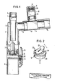
- the aerosol atomizer shown in FIG. 1 has a tubular lower part 1, which is connected to an electrically operated compressed air generator (not shown).
- a medication cup 2 is formed, which can hold a supply of aqueous medication solution.
- a likewise tubular upper part 5 is placed on the lower part 1. This upper part 5 has a round opening at the top, into which a hollow cylindrical supply air chimney 6 is inserted.
- the supply air chimney 6 protrudes up to directly above the air flow control 4, so that outside air is sucked in from above and passed into the area directly above the nozzle body 3.
- the incoming air mixes with the medicated aerosol mist.
- an inlet valve 7 is used in the supply air chimney 6, which is designed as a one-way valve.
- the inlet valve 7 is removable and is held by a cap 8 screwed onto the upper end of the supply air chimney 6.
- valve opening 9 Through which the introduced compressed air can escape into the environment before it flows into the nozzle body.
- the valve opening 9 can be closed by pressing a valve button 10.
- the valve button 10 must be pivoted against the action of a spring 11 in the direction of the lower part 1, whereby an elastic button seal 12 presses against the valve opening 9 and closes it airtight.
- the aerosol generation can thus be interrupted during exhalation without the electric compressed air generator having to be switched off. If the valve button 10 is pressed, the nebulization of the medication solution begins immediately.
- an outlet neck 13 with a round cross section is formed on the side, through which the mixture of supply air and medicament-containing aerosol emerges.
- a T-shaped distributor piece 14 connects to the outlet connection 13.
- a mouthpiece 15 for the patient is attached to the distributor piece 14.
- An exhalation resistor 16 is connected to the middle connection piece of the distributor piece 14.
- the exhalation resistor 16 contains a perforated disk 17 which is held in its intended position transverse to the direction of flow by means of a screwed-on cap 18.
- An outlet valve 19 is arranged between the distributor piece 14 and the exhalation resistor 16, which in turn is designed as a one-way valve.
- the patient inhales through the mouthpiece 15, at the same time pressing the valve button 10.
- the outlet valve 19 upstream of the exhalation resistor 16 is closed while the inlet valve 7 is open, so that outside air can only flow in through the supply air chimney 6. If the patient then exhales, the direction of flow within the distributor piece 14 is reversed.
- the outlet valve 19 in front of the exhalation resistor 16 opens, while the inlet valve 7 on the supply air chimney 6 closes due to the acting pressure.
- the exhaled air can now only get outside through the hole in the perforated disc 17 of the exhalation resistor 16.
- the aerosol atomization can be interrupted by releasing the valve button 10.
- a closable opening 24 for connecting a pressure measuring device (not shown) is provided on the distributor piece 14.
- a highly porous filter 25 which retains the remaining medication contained in the exhaled air.
- Fig. 2 shows the exhaust valve 19. It consists of a ring insert 20, on the end face 21 of a flap 22 is hinged on one side.
- the flap 22 is made of rubber-elastic material and is fastened by means of two pins 23 on the end face 21 of the ring insert 20.
- the ring insert 20 itself and the pins 23 are made of plastic.
- the flap 22 seals against the flat end face 21.
- the flexible flap 22 lifts off into the position shown, so that the valve opens.
- the inlet valve 7 on the supply air chimney 6 is of the same type as the outlet valve 19 described and shown in FIG. 2.
Abstract
Description
- Die Erfindung betrifft einen Aerosol-Zerstäuber zur Inhalationsbehandlung erkrankter Atemwege. Dieser hat ein Unterteil, in das Druckluft eingeleitet wird, einen Medikamentenbecher zur Aufnahme eines Vorrats von wäßriger Medikamenten-Lösung, eine Zerstäubungseinrichtung zur Zerstäubung der Medikamenten-Lösung in einen feinen Aerosol-Nebel mittels der Druckluft, ferner einen Zuluftkamin, durch den Zuluft in den Bereich über der Zerstäubungseinrichtung angesaugt wird, einen Auslaßstutzen für das Gemisch aus Aerosol und Zuluft, und ein Mundstück für den Patienten, welches mit dem Auslaßstutzen in Verbindung steht.
- Derartige Aerosol-Zerstäuber werden an einen elektrisch betriebenen Drucklufterzeuger angeschlossen. Über das Mundstück inhaliert der Patient den medikamentenhaltigen feinen Tröpfchennebel. Nur der kleinere Teil der insgesamt eingeatmeten Luft wird dabei von dem Kompressor des Drucklufterzeugers geliefert; im Bereich über der Zerstäubungeinrichtung wird das mittels der Druckluft aus der flüssigen Medikamenten-Lösung zerstäubte Aerosol mit Zuluft vermischt, welche über einen Zuluftkamin von oben zugeführt wird. Vor dem Ausatmen wird der Aerosol-Zerstäuber vom Mund abgesetzt, da ein Wiedereinblasen der Ausatemluft in das Gerät unsinnig wäre. Während dieser Zeit wird die Aerosol-Erzeugung unterbrochen, um nicht unnötig Medikamentenlösung zu verbrauchen.
- Patienten, welche ihre Atemwegserkrankungen durch Inhalation von Medikamenten-Nebel behandeln müssen, leiden oft gleichzeitig auch an Atemwegverschlüssen. Bei solchen Patienten findet eine weitere Therapieform Anwendung, bei der das Ausatmen der verbrauchten Luft nicht direkt in die Umgebung, sondern über einen genau definierten Strömungswiderstand, eine sog. Stenose, erfolgt. Das Ausatmen gegen einen gewissen Widerstand baut Sekretionen in den Atemwegen ab und wirkt so Atemwegverschlüssen entgegen. Patienten, die an Atemwegverschlüssen leiden und außerdem auch gezwungen sind, durch Inhalation eines medikamentenhaltigen Aerosols ihre Atemwegerkrankungen zu behandeln, mußten bisher in zwei zeitlich voneinander getrennten Sitzungen behandelt werden. Es war bisher nicht möglich, die beiden Therapieformen der Benutzung eines Inhalators und des Ausatmens gegen einen Atemwiderstand während einer einzigen Behandlungssitzung zu kombinieren.
- Aufgabe vorliegender Erfindung ist es daher, einen Aerosol-Zerstäuber zur Inhalationsbehandlung erkrankter Atemwege so weiterzubilden, daß sich mit diesem beide Therapieformen, nämlich sowohl Inhalierung eines medikamentenhaltigen Aerosols als auch Ausatmen gegen einen bestimmten Widerstand, verbinden lassen.
- Bei der Lösung dieser Aufgabe wird ausgegangen von einem Aerosol-Zerstäuber der eingangs erwähnten Art. Gelöst wird die Aufgabe dadurch, daß ein als Einwegventil ausgebildetes Einlaßventil am Zuluftkamin vorgesehen ist, ferner ein zwischen Auslaßstutzen und Mundstück angeordnetes Verteilerstück, ein an das Verteilerstück angeschlossener Ausatemwiderstand, gegen den der Patient ausatmet, und schließlich ein als Einwegventil ausgebildetes Auslaßventil zwischen Verteilerstück und Ausatemwiderstand.
- Während der Behandlung inhaliert der Patient wie gewohnt den von der Zerstäubungseinrichtung erzeugten Aerosol-Nebel, vermischt mit durch den Zuluftkamin zugeführter Außenluft. Zum Ausatmen wird das Gerät jedoch nicht, wie bisher, vom Mund abgesetzt; der Patient atmet vielmehr über das Mundstück und das Verteilerstück gegen den Ausatemwiderstand aus. Das als Einwegventil ausgebildete Einlaßventil am Zuluftkamin verhindert dabei ein Entweichen von Ausatemluft entgegen der Strömungsrichtung der Zuluft. Das unmittelbar vor dem Ausatemwiderstand angeordnete, ebenfalls als Einwegventil ausgebildete Auslaßventil ist während des Ausatmens geöffnet, verhindert jedoch während der Inhalationsphase ein unerwünschtes Einströmen von Außenluft über den Ausatemwiderstand entgegen der vorgesehenen Strömungsrichtung. Die abwechselnd öffnenden bzw. schließenden Einlaß- und Auslaßventile steuern die Luftströmungen also in der gewünschten Weise. Der mit der Erfindung geschaffene Aerosol-Zerstäuber erlaubt gleichzeitig sowohl eine atemunterstützende Inhalationsbehandlung wie auch eine Atemtherapie mittels künstlichem Ausatemwiderstand während einer einzigen Behandlungssitzung. Die erfindungsgemäße Vorrichtung stellt somit eine Kombination zwischen einem Aerosol-Zerstäuber und einer Atemvorrichtung für Stenose-Behandlung dar.
- In vorteilhafter Weiterbildung des Aerosol-Zerstäubers gemäß der Erfindung ist der Ausatemwiderstand auf das Verteilerstück aufsteckbar; dieser läßt sich dann leicht austauschen, um den Strömungswiderstand dem jeweiligen Therapiezweck anzupassen.
- Vorzugsweise umfaßt der Ausatemwiderstand eine Lochscheibe, welche das Drosselelement darstellt. Der Ausatemwiderstand kann aber auch mittels einstellbarer Ausblasöffnungen, durch welche die ausgeatmete Luft ins Freie gelangt, gebildet werden. Zweckmäßig ist es, die Lochscheibe austauschbar zu montieren; dabei kann die Lochscheibe beispielsweise von einer aufgeschraubten oder aufgedrückten Kappe in ihrer vorgesehenen Lage gehalten werden.
- Von Vorteil ist es ferner, wenn auch das Verteilerstück auf den Auslaßstutzen aufsteckbar ist und ebenso das Mundstück mit dem Verteilerstück bzw. der Zuluftkamin mit dem Oberteil des Aerosol-Zerstäubers steckbar verbunden ist. Das Gerät läßt sich so auf einfache Weise in seine wesentlichen Bestandteile zerlegen und reinigen bzw. desinfizieren. Auch das Einlaßventil am Zuluftkamin sowie das Auslaßventil zwischen Verteilerstück und Ausatemwiderstand sollten zu Reinigungszwecken demontierbar sein.
- Bevorzugt wird eine Ausführung, bei der das Auslaßventil und das Einlaßventil aus einem Ringeinsatz und einer gegen die Stirnseite dieses Ringeinsatzes abdichtenden, einseitig angelenkten Klappe besteht. Bevorzugt besteht die Klappe aus flexiblem, insbesondere gummielastischen Material. Die Klappe kann auf einfache Weise mittels einer oder mehrerer, vorzugsweise zwei Stiften auf dem Ringeinsatz befestigt sein. Derartig ausgebildete Einwegventile sind in der Herstellung einfach, dichten gut ab und zeichnen sich durch eine lange Lebensdauer aus.
- Besonders vorteilhaft ist die Ausführung des Verteilerstücks als T-Stück. Der Ausatemwiderstand ist dann an dessen mittlerem Stutzen angeschlossen. Diese geometrische Ausgestaltung zeichnet sich wegen der geradlinigen Verbindung zwischen Auslaßstutzen und Mundstück durch einen besonders geringen Strömungswiderstand beim Einatmen aus, so daß das medikamentenhaltige Aerosol weitgehend ungehindert in den Rachen des Patienten gelangt.
- Am Verteilerstück kann ferner eine verschließbare Öffnung vorgesehen sein, an welcher eine Druckmeßvorrichtung anschließbar ist. Der von den Lungen des Patienten aufzubringende Druck beim Ausatmen kann so exakt kontrolliert werden.
- Ein zusätzliches Filter, das vor oder nach dem Ausatemwiderstand angeordnet sein kann, verhindert eine oft unerwünschte Kontaminierung der Umgebungsluft mit Medikamentenresten, welche noch in der Ausatemluft enthalten sind.
- Ein Ausführungsbeispiel der Erfindung wird nachstehend anhand der beigefügten Zeichnungen näher erläutert. Es zeigen:
- Fig. 1 Einen Aerosol-Zerstäuber, mit aufsteckbarem T-förmigen Verteilerstück, in einem Schnittbild;
- Fig. 2 das in dem Aerosol-Zerstäuber gemäß Fig. 1 eingesetzte Auslaßventil, in einer vergrößerten perspektivischen Darstellung.
- Der in Fig. 1 dargestellte Aerosol-Zerstäuber weist ein rohrförmiges Unterteil 1 auf, welches mit einem (nicht dargestellten) elektrisch betriebenen Drucklufterzeuger in Verbindung steht. Im Unterteil 1 ist ein Medikamentenbecher 2 ausgebildet, welcher einen Vorrat von wäßriger Medikamenten-Lösung aufnehmen kann. Ein koaxial in der Mitte des Medikamentenbechers 2 angeordneter Düsenkörper 3 und ein auf diesem aufgesetztes Luftstromsteuer 4 bilden gemeinsam eine Zerstäubungseinrichtung, welche die flüssige Medikamenten-Lösung mittels der Druckluft, die durch Bohrungen innerhalb des Düsenkörpers 3 geblasen wird, in einen feinen Aerosol-Nebel zerstäubt. Auf das Unterteil 1 ist ein ebenfalls rohrförmiges Oberteil 5 aufgesetzt. Dieses Oberteil 5 weist oben eine runde Öffnung auf, in welche ein hohlzylindrischer Zuluftkamin 6 eingesetzt ist. Mit seinem unteren Ende ragt der Zuluftkamin 6 bis unmittelbar über das Luftstromsteuer 4, so daß Außenluft von oben angesaugt und in den Bereich unmittelbar über dem Düsenkörper 3 geleitet wird. Die eingeleitete Zuluft vermischt sich mit dem medikamentenhaltigen Aerosol-Nebel. An seinem oberen Ende ist in den Zuluftkamin 6 ein Einlaßventil 7 eingesetzt, welches als Einwegventil ausgebildet ist. Das Einlaßventil 7 ist demontierbar und wird von einer auf das obere Ende des Zuluftkamins 6 aufgeschraubten Kappe 8 gehalten.
- Am Unterteil 1 ist ferner eine kleine Ventilöffnung 9 vorgesehen, durch welche die eingeleitete Druckluft in die Umgebung entweichen kann, bevor sie in den Düsenkörper einströmt. Die Ventilöffnung 9 kann durch Betätigung einer Ventiltaste 10 verschlossen werden. Hierzu muß die Ventiltaste 10 entgegen der Wirkung einer Feder 11 in Richtung des Unterteils 1 verschwenkt werden, wodurch sich eine elastische Tastendichtung 12 auf die Ventilöffnung 9 preßt und diese luftdicht verschließt. Mittels der Ventiltaste 10 kann somit die Aerosol-Erzeugung während des Ausatmens unterbrochen werden, ohne daß hierzu der elektrische Drucklufterzeuger abgeschaltet werden müßte. Wird die Ventiltaste 10 gedrückt, setzt sofort die Vernebelung der Medikamenten-Lösung ein.
- Am Oberteil 5 ist seitlich ein im Querschnitt runder Auslaßstutzen 13 angeformt, über den das Gemisch aus Zuluft und medikamentenhaltigem Aerosol austritt. An den Auslaßstutzen 13 schließt sich ein T-förmiges Verteilerstück 14 an. Ein Mundstück 15 für den Patienten ist auf das Verteilerstück 14 aufgesteckt. An den mittleren Stutzen des Verteilerstücks 14 ist ein Ausatemwiderstand 16 angeschlossen. Als Drosselelement enthält der Ausatemwiderstand 16 eine Lochscheibe 17, welche mittels einer aufgeschraubten Kappe 18 in ihrer vorgesehenen Lage quer zur Strömungsrichtung gehalten ist. Zwischen dem Verteilerstück 14 und dem Ausatemwiderstand 16 ist ein Auslaßventil 19 angeordnet, welches wiederum als Einwegventil ausgebildet ist.
- Zur Inhalation von medikamentenhaltigem Aerosol atmet der Patient durch das Mundstück 15 ein, wobei er gleichzeitig die Ventiltaste 10 drückt. Das Auslaßventil 19 vor dem Ausatemwiderstand 16 ist dabei geschlossen, während das Einlaßventil 7 geöffnet ist, so daß Außenluft ausschließlich durch den Zuluftkamin 6 einströmen kann. Atmet der Patient anschließend aus, so kehrt sich die Strömungsrichtung innerhalb des Verteilerstücks 14 um. Das Auslaßventil 19 vor dem Ausatemwiderstand 16 öffnet, während das Einlaßventil 7 am Zuluftkamin 6 infolge des einwirkenden Druckes schließt. Die ausgeatmete Luft kann jetzt nur durch das Loch in der Lochscheibe 17 des Ausatemwiderstands 16 ins Freie gelangen. Die Aerosol-Vernebelung kann solange durch Loslassen der Ventiltaste 10 unterbrochen werden.
- Am Verteilerstück 14 ist eine verschließbare Öffnung 24 zum Anschluß einer (nicht dargestellten) Druckmeßvorrichtung vorgesehen. Unmittelbar vor der Lochscheibe 17 des Ausatemwiderstands 16 ist ein hochporöses Filter 25 angeordnet, das das in der Ausatemluft enthaltene restliche Medikament zurückhält.
- Fig. 2 zeigt das Auslaßventil 19. Es besteht aus einem Ringeinsatz 20, auf dessen Stirnseite 21 eine Klappe 22 einseitig angelenkt ist. Die Klappe 22 besteht aus gummielastischem Material und ist mittels zweier Stifte 23 auf der Stirnseite 21 des Ringseinsatzes 20 befestigt. Der Ringeinsatz 20 selbst sowie die Stifte 23 bestehen aus Kunststoff. In geschlossenem Zustand dichtet die Klappe 22 gegenüber der ebenen Stirnseite 21 ab. Bei Durchströmung in Pfeilrichtung von unten nach oben hebt die flexible Klappe 22 in die gezeigte Stellung ab, so daß das Ventil öffnet. - Das Einlaßventil 7 am Zuluftkamin 6 ist von derselben Art wie das beschriebene und in Fig. 2 dargestellte Auslaßventil 19.
- Alle wesentlichen Einzelteile des Aerosol-Zerstäubers sind klemmend oder schraubbar miteinander verbunden. So sind Verteilerstück 14, Ausatemwiderstand 16, Mundstück 15 und Auslaßstutzen 13 jeweils ineinander gesteckt und lassen sich zu Reinigungszwecken leicht voneinander abziehen.
-
- 1 Unterteil
- 2 Medikamentenbecher
- 3 Düsenkörper
- 4 Luftstromsteuer
- 5 Oberteil
- 6 Zuluftkamin
- 7 Einlaßventil (an 6)
- 8 Kappe (auf 6)
- 9 Ventilöffnung (in 1)
- 10 Ventiltaste
- 11 Feder (an 10)
- 12 Tastendichtung (an 10)
- 13 Auslaßstutzen
- 14 Verteilerstück
- 15 Mundstück
- 16 Ausatemwiderstand
- 17 Lochscheibe (von 16)
- 18 Kappe (auf 16)
- 19 Auslaßventil (zwischen 14 und 16)
- 20 Ringeinsatz (von 19)
- 21 Stirnseite (von 20)
- 22 Klappe (von 19)
- 23 Stifte
- 24 Öffnung (in 14)
- 25 Filter (in 14)
Claims (15)
- einem Unterteil (1), in das Druckluft eingeleitet wird,
- einem Medikamentenbecher (2) zur Aufnahme eines Vorrats von wäßriger Medikamenten-Lösung,
- einer Zerstäubungseinrichtung (3, 4) zur Zerstäubung der Medikamenten-Lösung in einen feinen Aerosol-Nebel mittels der Druckluft,
- einem Zuluftkamin (6), durch den Zuluft in den Bereich über der Zerstäubungseinrichtung (3, 4) angesaugt wird,
- einem Auslaßstutzen (13) für das Gemisch aus Aerosol und Zuluft, und
- einem Mundstück (15) für den Patienten, welches mit dem Auslaßstutzen (13) in Verbindung steht,
gekennzeichnet durch
- ein als Einwegventil ausgebildetes Einlaßventil (7) am Zuluftkamin (6),
- ein zwischen Auslaßstutzen (13) und Mundstück (15) angeordnetes Verteilerstück (14),
- einen an das Verteilerstück (14) angeschlossenen Ausatemwiderstand (16), gegen den der Patient ausatmet, und
- ein als Einwegventil ausgebildetes Auslaßventil (19) zwischen Verteilerstück (14) und Ausatemwiderstand (16).
Priority Applications (4)
| Application Number | Priority Date | Filing Date | Title |
|---|---|---|---|
| EP87103416A EP0281650B1 (de) | 1987-03-10 | 1987-03-10 | Aerosol-Zerstäuber |
| DE8703534U DE8703534U1 (de) | 1987-03-10 | 1987-03-10 | |
| AT87103416T ATE72997T1 (de) | 1987-03-10 | 1987-03-10 | Aerosol-zerstaeuber. |
| DE8787103416T DE3777157D1 (de) | 1987-03-10 | 1987-03-10 | Aerosol-zerstaeuber. |
Applications Claiming Priority (1)
| Application Number | Priority Date | Filing Date | Title |
|---|---|---|---|
| EP87103416A EP0281650B1 (de) | 1987-03-10 | 1987-03-10 | Aerosol-Zerstäuber |
Publications (2)
| Publication Number | Publication Date |
|---|---|
| EP0281650A1 true EP0281650A1 (de) | 1988-09-14 |
| EP0281650B1 EP0281650B1 (de) | 1992-03-04 |
Family
ID=8196817
Family Applications (1)
| Application Number | Title | Priority Date | Filing Date |
|---|---|---|---|
| EP87103416A Expired - Lifetime EP0281650B1 (de) | 1987-03-10 | 1987-03-10 | Aerosol-Zerstäuber |
Country Status (3)
| Country | Link |
|---|---|
| EP (1) | EP0281650B1 (de) |
| AT (1) | ATE72997T1 (de) |
| DE (1) | DE3777157D1 (de) |
Cited By (21)
| Publication number | Priority date | Publication date | Assignee | Title |
|---|---|---|---|---|
| DE9304771U1 (de) * | 1993-03-29 | 1993-05-19 | Kendall-Medizinische Erzeugnisse - Gmbh, 8425 Neustadt, De | |
| EP0895788A1 (de) * | 1997-08-06 | 1999-02-10 | PARI GmbH Spezialisten für effektive Inhalation | Inhalationstherapiegerät mit einem Ventil zur Begrenzung des Inspirationsflusses |
| US6805124B2 (en) | 1998-07-24 | 2004-10-19 | 3M Innovative Properties Company | Face mask that has a filtered exhalation valve |
| US6904906B2 (en) | 1998-11-06 | 2005-06-14 | Salter Labs | Nebulizer mouthpiece and accessories |
| US7131440B2 (en) | 2001-06-01 | 2006-11-07 | Pari Gmbh Spezialisten Fur Effektive Inhalation | Inhalation therapy apparatus having a valve for limiting the inspiration flow |
| WO2006114699A3 (en) * | 2005-04-28 | 2006-12-28 | Trudell Medical Int | Ventilator circuit and method for the use thereof |
| WO2007123664A1 (en) * | 2006-03-30 | 2007-11-01 | Allegiance Corporation | Nebulizer with flow-based fluidic control and related methods |
| WO2007123665A3 (en) * | 2006-03-30 | 2008-05-22 | Allegiance Corp | Nebulizer with pressure-based fluidic-control and related methods |
| US7849853B2 (en) | 2003-02-11 | 2010-12-14 | Trudell Medical International | Ventilator circuit and the method for the use thereof |
| US7905228B2 (en) | 2001-03-20 | 2011-03-15 | Trudell Medical International | Nebulizer apparatus and method |
| US8061352B2 (en) | 1996-02-13 | 2011-11-22 | Trudell Medical International | Aerosol delivery apparatus and method |
| US8074642B2 (en) | 2002-05-21 | 2011-12-13 | Trudell Medical International | Visual indicator for an aerosol medication delivery apparatus and system |
| US8151794B2 (en) | 2007-04-24 | 2012-04-10 | Trudell Medical International | Aerosol delivery system |
| US9242057B2 (en) | 2008-10-22 | 2016-01-26 | Trudell Medical International | Modular aerosol delivery system |
| US10786638B2 (en) | 2016-07-08 | 2020-09-29 | Trudell Medical International | Nebulizer apparatus and method |
| US10850050B2 (en) | 2016-05-19 | 2020-12-01 | Trudell Medical International | Smart valved holding chamber |
| WO2022056535A1 (en) * | 2020-09-10 | 2022-03-17 | Inspirx Inc. | Breath actuated nebulizer |
| US11497867B2 (en) | 2016-12-09 | 2022-11-15 | Trudell Medical International | Smart nebulizer |
| US11666801B2 (en) | 2018-01-04 | 2023-06-06 | Trudell Medical International | Smart oscillating positive expiratory pressure device |
| US11712175B2 (en) | 2019-08-27 | 2023-08-01 | Trudell Medical International | Smart oscillating positive expiratory pressure device with feedback indicia |
| US11839716B2 (en) | 2016-07-08 | 2023-12-12 | Trudell Medical International | Smart oscillating positive expiratory pressure device |
Families Citing this family (5)
| Publication number | Priority date | Publication date | Assignee | Title |
|---|---|---|---|---|
| US4955371A (en) * | 1989-05-08 | 1990-09-11 | Transtech Scientific, Inc. | Disposable inhalation activated, aerosol device for pulmonary medicine |
| ATE182801T1 (de) * | 1993-05-28 | 1999-08-15 | Pari Gmbh | Mundstück für inhalationstherapiegeräte |
| US6460539B1 (en) | 2000-09-21 | 2002-10-08 | 3M Innovative Properties Company | Respirator that includes an integral filter element, an exhalation valve, and impactor element |
| DE10345950A1 (de) | 2003-10-02 | 2005-05-19 | Pari GmbH Spezialisten für effektive Inhalation | Inhalationstherapievorrichtung mit Ventil |
| WO2021207187A1 (en) * | 2020-04-07 | 2021-10-14 | Inspirx, Inc. | Nebulizer apparatus with antimicrobial exhalation filter |
Citations (2)
| Publication number | Priority date | Publication date | Assignee | Title |
|---|---|---|---|---|
| EP0009667A1 (de) * | 1978-09-11 | 1980-04-16 | Michael T. Dr. Newhouse | Inhalationsgerät |
| DE8625936U1 (de) * | 1986-09-29 | 1986-11-06 | Brugger, Stephan, Dipl.-Wirtsch.-Ing.(FH), 8137 Berg | Atemvorrichtung |
-
1987
- 1987-03-10 EP EP87103416A patent/EP0281650B1/de not_active Expired - Lifetime
- 1987-03-10 DE DE8787103416T patent/DE3777157D1/de not_active Expired - Lifetime
- 1987-03-10 AT AT87103416T patent/ATE72997T1/de not_active IP Right Cessation
Patent Citations (2)
| Publication number | Priority date | Publication date | Assignee | Title |
|---|---|---|---|---|
| EP0009667A1 (de) * | 1978-09-11 | 1980-04-16 | Michael T. Dr. Newhouse | Inhalationsgerät |
| DE8625936U1 (de) * | 1986-09-29 | 1986-11-06 | Brugger, Stephan, Dipl.-Wirtsch.-Ing.(FH), 8137 Berg | Atemvorrichtung |
Cited By (36)
| Publication number | Priority date | Publication date | Assignee | Title |
|---|---|---|---|---|
| DE9304771U1 (de) * | 1993-03-29 | 1993-05-19 | Kendall-Medizinische Erzeugnisse - Gmbh, 8425 Neustadt, De | |
| US8061352B2 (en) | 1996-02-13 | 2011-11-22 | Trudell Medical International | Aerosol delivery apparatus and method |
| EP0895788A1 (de) * | 1997-08-06 | 1999-02-10 | PARI GmbH Spezialisten für effektive Inhalation | Inhalationstherapiegerät mit einem Ventil zur Begrenzung des Inspirationsflusses |
| US6805124B2 (en) | 1998-07-24 | 2004-10-19 | 3M Innovative Properties Company | Face mask that has a filtered exhalation valve |
| US6904906B2 (en) | 1998-11-06 | 2005-06-14 | Salter Labs | Nebulizer mouthpiece and accessories |
| US9907918B2 (en) | 2001-03-20 | 2018-03-06 | Trudell Medical International | Nebulizer apparatus and method |
| US9364618B2 (en) | 2001-03-20 | 2016-06-14 | Trudell Medical International | Nebulizer apparatus and method |
| US7905228B2 (en) | 2001-03-20 | 2011-03-15 | Trudell Medical International | Nebulizer apparatus and method |
| US7131440B2 (en) | 2001-06-01 | 2006-11-07 | Pari Gmbh Spezialisten Fur Effektive Inhalation | Inhalation therapy apparatus having a valve for limiting the inspiration flow |
| US9700689B2 (en) | 2002-05-21 | 2017-07-11 | Trudell Medical International | Medication delivery apparatus and system and methods for the use and assembly thereof |
| US10881816B2 (en) | 2002-05-21 | 2021-01-05 | Trudell Medical International | Medication delivery apparatus and system and methods for the use and assembly thereof |
| US8550067B2 (en) | 2002-05-21 | 2013-10-08 | Trudell Medical International | Visual indicator for an aerosol medication delivery apparatus and system |
| US9814849B2 (en) | 2002-05-21 | 2017-11-14 | Trudell Medical International | Medication delivery apparatus and system and methods for the use and assembly thereof |
| US8074642B2 (en) | 2002-05-21 | 2011-12-13 | Trudell Medical International | Visual indicator for an aerosol medication delivery apparatus and system |
| US7849853B2 (en) | 2003-02-11 | 2010-12-14 | Trudell Medical International | Ventilator circuit and the method for the use thereof |
| US8028697B2 (en) | 2005-04-28 | 2011-10-04 | Trudell Medical International | Ventilator circuit and method for the use thereof |
| US10864344B2 (en) | 2005-04-28 | 2020-12-15 | Trudell Medical International | Receptacle having a removable discharge nozzle and methods for reconfiguring a medication delivery apparatus and adminstering a medication |
| WO2006114699A3 (en) * | 2005-04-28 | 2006-12-28 | Trudell Medical Int | Ventilator circuit and method for the use thereof |
| US8905026B2 (en) | 2005-04-28 | 2014-12-09 | Trudell Medical International | Ventilator circuit and method for the use thereof |
| US9468735B2 (en) | 2005-04-28 | 2016-10-18 | Trudell Medical International | Ventilator circuit and method for the use thereof |
| US7841335B2 (en) | 2006-03-30 | 2010-11-30 | Carefusion 2200, Inc. | Nebulizer with flow-based fluidic control and related methods |
| US7841336B2 (en) | 2006-03-30 | 2010-11-30 | Carefusion 2200, Inc. | Nebulize with pressure-based fluidic control and related methods |
| WO2007123664A1 (en) * | 2006-03-30 | 2007-11-01 | Allegiance Corporation | Nebulizer with flow-based fluidic control and related methods |
| WO2007123665A3 (en) * | 2006-03-30 | 2008-05-22 | Allegiance Corp | Nebulizer with pressure-based fluidic-control and related methods |
| EP3034119A1 (de) * | 2006-03-30 | 2016-06-22 | CareFusion 2200 Inc. | Vernebler mit druckbasierter fluidiksteuerung und zugehörige verfahren |
| US8151794B2 (en) | 2007-04-24 | 2012-04-10 | Trudell Medical International | Aerosol delivery system |
| US10220176B2 (en) | 2007-04-24 | 2019-03-05 | Trudell Medical International | Aerosol delivery system |
| US8875706B2 (en) | 2007-04-24 | 2014-11-04 | Trudell Medical International | Aerosol delivery system |
| US9242057B2 (en) | 2008-10-22 | 2016-01-26 | Trudell Medical International | Modular aerosol delivery system |
| US10850050B2 (en) | 2016-05-19 | 2020-12-01 | Trudell Medical International | Smart valved holding chamber |
| US10786638B2 (en) | 2016-07-08 | 2020-09-29 | Trudell Medical International | Nebulizer apparatus and method |
| US11839716B2 (en) | 2016-07-08 | 2023-12-12 | Trudell Medical International | Smart oscillating positive expiratory pressure device |
| US11497867B2 (en) | 2016-12-09 | 2022-11-15 | Trudell Medical International | Smart nebulizer |
| US11666801B2 (en) | 2018-01-04 | 2023-06-06 | Trudell Medical International | Smart oscillating positive expiratory pressure device |
| US11712175B2 (en) | 2019-08-27 | 2023-08-01 | Trudell Medical International | Smart oscillating positive expiratory pressure device with feedback indicia |
| WO2022056535A1 (en) * | 2020-09-10 | 2022-03-17 | Inspirx Inc. | Breath actuated nebulizer |
Also Published As
| Publication number | Publication date |
|---|---|
| EP0281650B1 (de) | 1992-03-04 |
| ATE72997T1 (de) | 1992-03-15 |
| DE3777157D1 (de) | 1992-04-09 |
Similar Documents
| Publication | Publication Date | Title |
|---|---|---|
| EP0281650B1 (de) | Aerosol-Zerstäuber | |
| DE69633306T2 (de) | Beatmungskreis für einen zerstäuber | |
| DE2038618C3 (de) | Handbetätigtes Druck-Atmungsgerät | |
| DE3043377C2 (de) | ||
| DE69729071T2 (de) | Vernebler | |
| DE2847681C2 (de) | Trachealtubus | |
| DE19953317C1 (de) | Inhalationsvernebler | |
| EP0895788B1 (de) | Inhalationstherapiegerät mit einem Ventil zur Begrenzung des Inspirationsflusses | |
| EP0983103B1 (de) | Vorrichtung zur applikation eines medikament-aerosols über die lunge | |
| DE2808499C2 (de) | Gerät zum Erzeugen eines fein verteilten Flüssigkeitsnebels | |
| DE4409076C1 (de) | Vorrichtung zur Beatmung von Patienten | |
| EP1695730B1 (de) | Bauteil für eine Inhalationsvorrichtung und Inhalationsvorrichtung mit diesem Bauteil | |
| DD145887A5 (de) | Inhalationsgeraet | |
| DE2915684C2 (de) | Atmungsgerät | |
| DE2331525A1 (de) | Atemgeraet, insbesondere fuer heilzwecke | |
| DE19902847C1 (de) | Medikamentenvernebler zur Inhalationsbehandlung mit kombiniertem Ein-/Ausatmungsventil | |
| EP0262239B1 (de) | Atemvorrichtung | |
| EP0626180A1 (de) | Mundstück für Inhalationstherapiegeräte | |
| DE19902844C1 (de) | Medikamentenvernebler mit verbessertem Prallschirm | |
| DE60003217T2 (de) | Inhalator zur behandlung der bronchien von pferden | |
| EP1107809B1 (de) | Inhalator zum vernebeln von flüssigkeiten | |
| DE3915500C2 (de) | ||
| EP1531891A1 (de) | Vorrichtung zur beeinflussung von gasflüssen | |
| WO2018010734A1 (de) | Verneblereinheit mit wechselbarem mundstück | |
| DE3513628C1 (de) | Vorrichtung zum Inhalieren von Allergenen |
Legal Events
| Date | Code | Title | Description |
|---|---|---|---|
| PUAI | Public reference made under article 153(3) epc to a published international application that has entered the european phase |
Free format text: ORIGINAL CODE: 0009012 |
|
| AK | Designated contracting states |
Kind code of ref document: A1 Designated state(s): AT BE CH DE ES FR GB GR IT LI NL SE |
|
| 17P | Request for examination filed |
Effective date: 19890131 |
|
| 17Q | First examination report despatched |
Effective date: 19900816 |
|
| GRAA | (expected) grant |
Free format text: ORIGINAL CODE: 0009210 |
|
| AK | Designated contracting states |
Kind code of ref document: B1 Designated state(s): AT BE CH DE ES FR GB GR IT LI NL SE |
|
| PG25 | Lapsed in a contracting state [announced via postgrant information from national office to epo] |
Ref country code: GR Free format text: LAPSE BECAUSE OF FAILURE TO SUBMIT A TRANSLATION OF THE DESCRIPTION OR TO PAY THE FEE WITHIN THE PRESCRIBED TIME-LIMIT Effective date: 19920304 |
|
| REF | Corresponds to: |
Ref document number: 72997 Country of ref document: AT Date of ref document: 19920315 Kind code of ref document: T |
|
| REF | Corresponds to: |
Ref document number: 3777157 Country of ref document: DE Date of ref document: 19920409 |
|
| ET | Fr: translation filed | ||
| ITF | It: translation for a ep patent filed |
Owner name: NOTARBARTOLO & GERVASI S.R.L. |
|
| GBT | Gb: translation of ep patent filed (gb section 77(6)(a)/1977) | ||
| PG25 | Lapsed in a contracting state [announced via postgrant information from national office to epo] |
Ref country code: ES Free format text: LAPSE BECAUSE OF FAILURE TO SUBMIT A TRANSLATION OF THE DESCRIPTION OR TO PAY THE FEE WITHIN THE PRESCRIBED TIME-LIMIT Effective date: 19920615 |
|
| PLBE | No opposition filed within time limit |
Free format text: ORIGINAL CODE: 0009261 |
|
| STAA | Information on the status of an ep patent application or granted ep patent |
Free format text: STATUS: NO OPPOSITION FILED WITHIN TIME LIMIT |
|
| 26N | No opposition filed | ||
| EAL | Se: european patent in force in sweden |
Ref document number: 87103416.1 |
|
| PGFP | Annual fee paid to national office [announced via postgrant information from national office to epo] |
Ref country code: GB Payment date: 19990312 Year of fee payment: 13 |
|
| PGFP | Annual fee paid to national office [announced via postgrant information from national office to epo] |
Ref country code: SE Payment date: 19990315 Year of fee payment: 13 |
|
| PGFP | Annual fee paid to national office [announced via postgrant information from national office to epo] |
Ref country code: BE Payment date: 19990324 Year of fee payment: 13 |
|
| PGFP | Annual fee paid to national office [announced via postgrant information from national office to epo] |
Ref country code: FR Payment date: 19990326 Year of fee payment: 13 |
|
| PGFP | Annual fee paid to national office [announced via postgrant information from national office to epo] |
Ref country code: AT Payment date: 19990330 Year of fee payment: 13 |
|
| PGFP | Annual fee paid to national office [announced via postgrant information from national office to epo] |
Ref country code: NL Payment date: 19990331 Year of fee payment: 13 |
|
| PG25 | Lapsed in a contracting state [announced via postgrant information from national office to epo] |
Ref country code: GB Free format text: LAPSE BECAUSE OF NON-PAYMENT OF DUE FEES Effective date: 20000310 Ref country code: AT Free format text: LAPSE BECAUSE OF NON-PAYMENT OF DUE FEES Effective date: 20000310 |
|
| PG25 | Lapsed in a contracting state [announced via postgrant information from national office to epo] |
Ref country code: SE Free format text: LAPSE BECAUSE OF NON-PAYMENT OF DUE FEES Effective date: 20000311 |
|
| PG25 | Lapsed in a contracting state [announced via postgrant information from national office to epo] |
Ref country code: BE Free format text: LAPSE BECAUSE OF NON-PAYMENT OF DUE FEES Effective date: 20000331 |
|
| BERE | Be: lapsed |
Owner name: BRUGGER STEPHAN Effective date: 20000331 |
|
| PG25 | Lapsed in a contracting state [announced via postgrant information from national office to epo] |
Ref country code: NL Free format text: LAPSE BECAUSE OF NON-PAYMENT OF DUE FEES Effective date: 20001001 |
|
| GBPC | Gb: european patent ceased through non-payment of renewal fee |
Effective date: 20000310 |
|
| EUG | Se: european patent has lapsed |
Ref document number: 87103416.1 |
|
| PG25 | Lapsed in a contracting state [announced via postgrant information from national office to epo] |
Ref country code: FR Free format text: LAPSE BECAUSE OF NON-PAYMENT OF DUE FEES Effective date: 20001130 |
|
| NLV4 | Nl: lapsed or anulled due to non-payment of the annual fee |
Effective date: 20001001 |
|
| REG | Reference to a national code |
Ref country code: FR Ref legal event code: ST |
|
| PGFP | Annual fee paid to national office [announced via postgrant information from national office to epo] |
Ref country code: CH Payment date: 20010629 Year of fee payment: 15 |
|
| PG25 | Lapsed in a contracting state [announced via postgrant information from national office to epo] |
Ref country code: LI Free format text: LAPSE BECAUSE OF NON-PAYMENT OF DUE FEES Effective date: 20020331 Ref country code: CH Free format text: LAPSE BECAUSE OF NON-PAYMENT OF DUE FEES Effective date: 20020331 |
|
| REG | Reference to a national code |
Ref country code: CH Ref legal event code: PL |
|
| PGFP | Annual fee paid to national office [announced via postgrant information from national office to epo] |
Ref country code: DE Payment date: 20030530 Year of fee payment: 17 |
|
| PG25 | Lapsed in a contracting state [announced via postgrant information from national office to epo] |
Ref country code: DE Free format text: LAPSE BECAUSE OF NON-PAYMENT OF DUE FEES Effective date: 20041001 |
|
| PG25 | Lapsed in a contracting state [announced via postgrant information from national office to epo] |
Ref country code: IT Free format text: LAPSE BECAUSE OF NON-PAYMENT OF DUE FEES;WARNING: LAPSES OF ITALIAN PATENTS WITH EFFECTIVE DATE BEFORE 2007 MAY HAVE OCCURRED AT ANY TIME BEFORE 2007. THE CORRECT EFFECTIVE DATE MAY BE DIFFERENT FROM THE ONE RECORDED. Effective date: 20050310 |