EP0283062A2 - Apparatus for examining the illumination or irradiation of a cavity in a body - Google Patents
Apparatus for examining the illumination or irradiation of a cavity in a body Download PDFInfo
- Publication number
- EP0283062A2 EP0283062A2 EP88200240A EP88200240A EP0283062A2 EP 0283062 A2 EP0283062 A2 EP 0283062A2 EP 88200240 A EP88200240 A EP 88200240A EP 88200240 A EP88200240 A EP 88200240A EP 0283062 A2 EP0283062 A2 EP 0283062A2
- Authority
- EP
- European Patent Office
- Prior art keywords
- cavity
- cannula
- accessory
- capillaries
- mandrin
- Prior art date
- Legal status (The legal status is an assumption and is not a legal conclusion. Google has not performed a legal analysis and makes no representation as to the accuracy of the status listed.)
- Granted
Links
- 0 C=C1C2O*2=CCC1 Chemical compound C=C1C2O*2=CCC1 0.000 description 1
Images

Classifications
-
- A—HUMAN NECESSITIES
- A61—MEDICAL OR VETERINARY SCIENCE; HYGIENE
- A61B—DIAGNOSIS; SURGERY; IDENTIFICATION
- A61B1/00—Instruments for performing medical examinations of the interior of cavities or tubes of the body by visual or photographical inspection, e.g. endoscopes; Illuminating arrangements therefor
- A61B1/307—Instruments for performing medical examinations of the interior of cavities or tubes of the body by visual or photographical inspection, e.g. endoscopes; Illuminating arrangements therefor for the urinary organs, e.g. urethroscopes, cystoscopes
-
- A—HUMAN NECESSITIES
- A61—MEDICAL OR VETERINARY SCIENCE; HYGIENE
- A61N—ELECTROTHERAPY; MAGNETOTHERAPY; RADIATION THERAPY; ULTRASOUND THERAPY
- A61N5/00—Radiation therapy
- A61N5/06—Radiation therapy using light
- A61N5/0613—Apparatus adapted for a specific treatment
- A61N5/062—Photodynamic therapy, i.e. excitation of an agent
-
- A—HUMAN NECESSITIES
- A61—MEDICAL OR VETERINARY SCIENCE; HYGIENE
- A61N—ELECTROTHERAPY; MAGNETOTHERAPY; RADIATION THERAPY; ULTRASOUND THERAPY
- A61N5/00—Radiation therapy
- A61N5/06—Radiation therapy using light
- A61N5/0601—Apparatus for use inside the body
- A61N5/0603—Apparatus for use inside the body for treatment of body cavities
- A61N2005/061—Bladder and/or urethra
Definitions
- This invention relates to apparatus for examining and/or illuminating a cavity in a body, comprising a cannula with accessories which via the cannula can be disposed to extend into such cavity to be examined and/or to be illuminated, there being at least one accessory arranged to receive one or more conductors.
- the invention further relates to a method of examining and/or illuminating a cavity in a body, using the apparatus, in which the cannula of the apparatus is disposed so that one end extends into the cavity.
- German Offenlegungsschrift 3,323,365 An apparatus and method of the above kinds are disclosed in German Offenlegungsschrift 3,323,365.
- One possible application of the prior apparatus and method is to introduce the apparatus into the bladder of a human being or animal and internally illuminating the bladder for combatting malign or pre-malign conditions.
- Such a photodynamic therapy is described and elucidated in more detail in articles in the Journal of Urology, Volume 131 (1984) pp 884-887; Volume 133 (1985) pp 311-315; Volume 134 (1985) pp 675-678 and in CRC Critical Reviews in Oncology/Hematology, Volume 2, Issue 2 (1984) pp 83-116, among other articles.
- this method it is desirable that the entire wall of the bladder is uniformly illuminated.
- the light source should be disposed in a suitable location.
- a light-scattering liquid is introduced into the cavity (the bladder) in the illuminating mode.
- the light is scattered many times before reaching the bladder wall.
- the illumination of the wall becomes diffuse.
- the light intensity at the wall would be less dependent on the distance from the light source than would be the case without a scattering fluid.
- a substantially uniform illumination of the entire wall is claimed to be possible.
- the accessory arranged to receive conductors comprises a relatively stiff mandrin disposed for movement between a plurality of substantially parallel capillaries, each capillary containing, at least adjacent its end, a tubular body of translucent material, the ends of said tubular bodies remote from the respective capillaries being connected to each other and to the end of the mandrin, the apparatus optionally being arranged to receive, in addition to said accessory, at least one further accessory for introducing a light source into the cavity to be examined or illuminated; and with a method comprising introducing the accessory with mandrin and capillary into the cannula, moving the mandrin with the tubular bodies in the cavity until the end rests against the wall of the cavity, moving the tubular bodies, which as far as necessary are pre-shaped, further for them to come to rest against the wall of the cavity throughout their length outside the cannula and at suitable angles to each other, introducing a photodetector attached to the end of a fiber-type
- the apparatus and the method according to the invention it is possible not only to measure the light intensity at different critical positions on the bladder wall during the positioning of the light source, so that ultimately the optimum location of the light source can be determined, but also, during the illumination the light intensity can be checked, if desired continuously. This is useful especially during illumination as a part of a photodynamic therapy to prevent damage from underdosage or overdosage and to indicate the dosage of light with reasonable accuracy, so that the correlation between dose and effect can be recorded.
- the apparatus according to the invention is also applicable for examining the amount of radiation received in the wall of a cavity, for example in case parts located next to, or adjacent to the cavity are irradiated.
- no light detectors coupled with photoconductors are disposed in the tubes of the apparatus according to the invention, but instead detectors for ionizing radiation, coupled to suitable conductors.
- the tubular bodies disposed in at least a portion of the respective capillaries of the accessory of the apparatus according to the invention can suitably be tubules of a slightly deformable synthetic plastics material. Such tubules, for example of nylon, are very suitable for being pre-formed.
- the method according to the invention comprises first measuring the length of the cavity by moving the mandrin up to the wall of the cavity, removing the mandrin and capillaries with tubular bodies from the apparatus, pre-forming the tubular bodies using surroundings of elevated temperature, temporarily straightening the tubular bodies again, and re-introducing the mandrin with capillaries and tubular bodies into the apparatus.
- the pre-forming treatment can be effected, for example, by means of hot water.
- said at least one other accessory may be a tubular element with a fiber-optic photoconductor mounted for movement therein and arranged to be moved outside the tubular element.
- the fiber-optic photoconductor carries a light-diffusing bulb at the end to be moved outside the tubular element.
- the fiber-optic photoconductor is then arranged to be connected at its other end to a light source, for example, a laser. In this way the bulb becomes an isotropic light source which, provided arranged in the correct manner, uniformly illuminates the wall of the cavity, which may be filled with a clear liquid, for example, physiological saline.
- the accessory arranged to receive photoconductors preferably comprises three capillaries and three tubules disposed within said capillaries.
- the ends of the three tubules are deployed at an angle of about 120° relatively to each other until they rest like whalebones against the wall of the cavity.
- Detectors secured to fiber-optic photoconductors are moved through the capillaries up to the ends of the tubes.
- the photoconductors are coupled to suitable electronic processing equipment to provide for a continuous reading of the light intensity received by the detectors. By moving the light source the same intensity for each of the detectors can be aimed at. At the moment when that is reached, the light source has its optimum position.
- the apparatus according to the invention to be designed with more than three capillaries and tubules. This, however, does not produce any appreciable better results, and does increase the size of the equipment.
- the tubules of the apparatus according to the invention can be provided with a bar marking, and if desired, the detector fibers can also be provided with bar markings. In this way an accurate location of the detectors in the tubes can be realized.
- the apparatus according to the invention can be used, for example, to combat malign or pre-malign conditions in the wall of the human or animal bladder.
- This includes administering to the patient a photosensitive substance, which substance is preferentially absorbed by malign or pre-malign tissue.
- the substance accumulates in malign or pre-malign superficial growths in the wall of the bladder.
- the apparatus according to the invention is introduced as usual for cystoscopes, and the light source is positioned in the correct position with a laser source operated at a low intensity. Thereafter the treatment proper is effected by increasing the intensity.
- This treatment can be continuously monitored and controlled by means of the light detectors in the tubules of the one accessory, connected to the electronic signal processing apparatus.
- the apparatus according to the invention can also be used in examining cavities which are not by themselves able to retain a liquid.
- a balloon may be secured at the end of the apparatus over the top of the cannula, so that, in operation, the system of tubules is deployed into the balloon and the balloon thus forms an intermediate wall between the cavity wall and the system of tubules. It is noted in this connection that the use of a balloon is known per se from the above German Offenlegungsschrift 3,323,365.
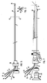
- Fig. 1 shows a side-elevational view of the cannula of one embodiment of the apparatus according to the invention.
- the cannula is in essence a conventional cystoscopic cannula of oval cross-sectional configuration.
- the hollow cannula tube is provided at one end with the conventional operating handle 2.
- Fig. 2 is a cross-sectional view of cannula 1, taken on the line II-II.
- Fig. 3 shows a conventional mandrin 3, which in essence consists of a rod with a handle 4 at one end and a hood-shaped element 5 at the other.
- Fig. 1 shows a side-elevational view of the cannula of one embodiment of the apparatus according to the invention.
- the cannula is in essence a conventional cystoscopic cannula of oval cross-sectional configuration.
- the hollow cannula tube is provided at one end with the conventional operating handle 2.
- Fig. 2 is a cross-sectional view of cannula 1, taken
- FIG. 4 illustrates how mandrin 3 and cannula 1 can be combined into one unit, with the hood 5 of mandrin 3 closing the more or less spoon-shaped open end 6 of the cannula.
- the apparatus according to the invention can be introduced, for example, with the tip into the bladder cervix of a patient. After the introduction of the cannula, the mandrin is removed, and the accessory illustrated in Fig. 5 is positioned in the canal of the cannula 1.
- the accessory illustrated in Fig. 5 comprises three essential parallel capillaries 7, 8 and 9, for example of stainless steel, attached to a suitable operating handle 10, so that, in the hollow handle 10, through which the capillaries extend to outside the handle, the capillaries leave a passage to which a supply tube 11 is connected. Through supply tube 11, further accessories can be introduced into cannula 1 in more or less fixed position relative to capillaries 7, 8 and 9, as will be described more fully hereinafter.
- a cross-sectional view of the system of capillaries, taken on the line VI-VI of Fig. 5, is illustrated in Fig. 6. Disposed in the capillaries are nylon tubules, i.e. tubules 12, 13 and 14 in the respective capillaries 7, 8 and 9.
- Tubules 12, 13 and 14 are transparent and, for example, have a diameter of less than 1.2 mm. At their end, the tubules are secured to a hinge system 15. Hinge system 15 is further secured to the end of a more or less stiff, filamentous mandrin 16, disposed for movement between capillaries 7, 8 and 9. By moving mandrin 16 forwardly, tubules 12, 13 and 14 are moved with the hinge system 15 relatively to the capillaries and are also pushed forwardly.
- Fig. 7 illustrates how the accessory of Fig. 5 is positioned in the cannula 1 of Fig. 1, while at the same time another accessory, essentially consisting of known cystoscope-optics, including a tubular body 17 and a handle with eyepiece 18, is disposed in cannula 1.
- cystoscope-optics Through the cystoscope-optics, the operator can observe what happens in the cavity into which the tip of the cannula 1 extends.
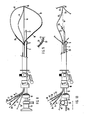
- the operation of the unit thus assembled is shown in more detail in Fig. 8.
- the mandrin 16 is operated to move the hinge system 15 with the tubules 12, 13 and 14 coupled to it forwardly relatively to cannula 1 until the hinge system 15 rests against the bladder wall. All this is realized by monitoring through the cystoscope-optics.
- the tubules 12, 13 and 14, which are pre-formed, bulge outwardly as soon as they are moved outside the capillaries 7, 8 and 9 and are pushed up and guided against the bladder wall one by one.
- the tubules 12, 13 and 14 accordingly follow the shape of the bladder wall, as shown diagrammatically in Fig. 8.
- the correct disposition of the tubules 12, 13 and 14 can be monitored by means of the cystoscope-optics, as the coupling through handle 18 and seals between optics and cannula 1 have been arranged so that the optics can rotate and move in and out independently of the cannula.
- the cannula 1 is fixed, because cannula 1 with mandrin 16 and capillaries 7, 8 and 9 constitute the support points for tubules 12, 13 and 14.
- tubules 12, 13 and 14 After tubules 12, 13 and 14 have been positioned, the optics can be removed. Furthermore, light detectors connected to fiber-optic photoconductors can be introduced into tubules 12, 13 and 14, so that these detectors are disposed approximately halfway the convex part of the respective tubules.
- Fig. 8 shows the fiber-optic photoconductors 19, 20 and 21, respectively guided in tubules 12, 13 and 14.
- Fig. 9 shows in detail how the isotropic fiber-detector 22 is disposed at the end of the fiber-optic photoconductor 20, and the whole is located within tubule 13, so that the detector is capable of measuring the light intensity of the bladder wall in situ through the thin transparent wall of tubule 13 (which has a thickness of less than about 0.1 mm).
- Fig. 10 illustrates how, in the illuminating phase, the cystoscope-optics (17, 18 in Fig. 8) has been removed and replaced by an accessory by means of which the light source is introduced.
- This accessory is in essence a thin hollow tube 23 with an operating handle 24. Passed through tube 23 of the accessory is a fiber-optic photoconductor 25 which outside the apparatus is coupled to a light source not shown, for example, a laser system.
- a light-scattering bulb 26 Mounted on the tip of the photoconductor 25 to be introduced into the cavity is a light-scattering bulb 26, which in operation serves as the light source for illuminating the wall of the cavity into which the end of the apparatus extends when installed in position.
- the accessory with the photoconductor 25 is arranged to rotate and slide relatively to cannula 1 independently thereof, while further the accessory may be provided with means for causing the end of photoconductor 25 with bulb 26 to deflect or bend somewhat.
- Fig. 10 shows such bending diagrammatically with an end in solid lines and an end in dotted lines. In this way sufficient freedom of movement is provided for the light source constituted by bulb 26 for it to be accurately disposed in the "optical center" of the cavity, guided by the observations by means of the detectors within tubules 12, 13 and 14.
- the fiber-optic photoconductor 25 is coupled to a light source, such as a laser system.
- the fiber-optic photoconductors 19, 20 and 21 of the detection system are coupled to photodiodes for light-to-current conversion. Reading is effected by conventional apparatus, analogue and/or digital. In illumination for therapeutic purposes, it is of importance that the integrated light dose should be measured, too. This comprises measures well-known to those skilled in the art, which need not be described in any detail herein.
Abstract
Description
- This invention relates to apparatus for examining and/or illuminating a cavity in a body, comprising a cannula with accessories which via the cannula can be disposed to extend into such cavity to be examined and/or to be illuminated, there being at least one accessory arranged to receive one or more conductors. The invention further relates to a method of examining and/or illuminating a cavity in a body, using the apparatus, in which the cannula of the apparatus is disposed so that one end extends into the cavity.
- An apparatus and method of the above kinds are disclosed in German Offenlegungsschrift 3,323,365. One possible application of the prior apparatus and method is to introduce the apparatus into the bladder of a human being or animal and internally illuminating the bladder for combatting malign or pre-malign conditions. Such a photodynamic therapy is described and elucidated in more detail in articles in the Journal of Urology, Volume 131 (1984) pp 884-887; Volume 133 (1985) pp 311-315; Volume 134 (1985) pp 675-678 and in CRC Critical Reviews in Oncology/Hematology, Volume 2, Issue 2 (1984) pp 83-116, among other articles. In this method it is desirable that the entire wall of the bladder is uniformly illuminated. Generally speaking, it is often desirable in examining and/or illuminating a cavity that the illumination should be uniform. For this purpose the light source should be disposed in a suitable location.
- In the method disclosed in the above Offenlegungsschrift, a light-scattering liquid is introduced into the cavity (the bladder) in the illuminating mode. As a result of the presence of this fluid, the light is scattered many times before reaching the bladder wall. As a consequence, the illumination of the wall becomes diffuse. According to the Offenlegungsschrift, the light intensity at the wall would be less dependent on the distance from the light source than would be the case without a scattering fluid. Also, a substantially uniform illumination of the entire wall is claimed to be possible.
- One disadvantage of the prior method and apparatus is that these are limited to applications using a light-scattering fluid. When a clear fluid is used, a uniform illumination is not possible without more ado, and even when a light-scattering fluid is used, such an illumination cannot be accomplished under all conditions. There was accordingly a need for an apparatus and a method enabling the light source to be better positioned, and enabling observations with regard to the illumination to be made both during positioning and, if desired, during illumination.
- It is an object of the present invention to provide a method and an apparatus in which the disadvantages of the prior method and apparatus, as outlined above, do not occur, or at any rate to a much lesser extent.
- The object contemplated is achieved, in accordance with the present invention, with an apparatus in which the accessory arranged to receive conductors comprises a relatively stiff mandrin disposed for movement between a plurality of substantially parallel capillaries, each capillary containing, at least adjacent its end, a tubular body of translucent material, the ends of said tubular bodies remote from the respective capillaries being connected to each other and to the end of the mandrin, the apparatus optionally being arranged to receive, in addition to said accessory, at least one further accessory for introducing a light source into the cavity to be examined or illuminated; and with a method comprising introducing the accessory with mandrin and capillary into the cannula, moving the mandrin with the tubular bodies in the cavity until the end rests against the wall of the cavity, moving the tubular bodies, which as far as necessary are pre-shaped, further for them to come to rest against the wall of the cavity throughout their length outside the cannula and at suitable angles to each other, introducing a photodetector attached to the end of a fiber-type photoconductor through each of the capillaries into each of the tubular bodies so that they are each positioned at a corresponding position virtually in the middle of the tube, and further intro ducing a light source through the cannula into the cavity, and moving said light source until the different light detectors each measure virtually the same amount of light, and then fixing the light source in that position.
- By means of the apparatus and the method according to the invention, it is possible not only to measure the light intensity at different critical positions on the bladder wall during the positioning of the light source, so that ultimately the optimum location of the light source can be determined, but also, during the illumination the light intensity can be checked, if desired continuously. This is useful especially during illumination as a part of a photodynamic therapy to prevent damage from underdosage or overdosage and to indicate the dosage of light with reasonable accuracy, so that the correlation between dose and effect can be recorded.
- The apparatus according to the invention is also applicable for examining the amount of radiation received in the wall of a cavity, for example in case parts located next to, or adjacent to the cavity are irradiated. In such an application, no light detectors coupled with photoconductors are disposed in the tubes of the apparatus according to the invention, but instead detectors for ionizing radiation, coupled to suitable conductors.
- The tubular bodies disposed in at least a portion of the respective capillaries of the accessory of the apparatus according to the invention can suitably be tubules of a slightly deformable synthetic plastics material. Such tubules, for example of nylon, are very suitable for being pre-formed. In one suitable embodiment, the method according to the invention comprises first measuring the length of the cavity by moving the mandrin up to the wall of the cavity, removing the mandrin and capillaries with tubular bodies from the apparatus, pre-forming the tubular bodies using surroundings of elevated temperature, temporarily straightening the tubular bodies again, and re-introducing the mandrin with capillaries and tubular bodies into the apparatus. The pre-forming treatment can be effected, for example, by means of hot water.
- In the apparatus according to the invention, said at least one other accessory may be a tubular element with a fiber-optic photoconductor mounted for movement therein and arranged to be moved outside the tubular element. Preferably, the fiber-optic photoconductor carries a light-diffusing bulb at the end to be moved outside the tubular element. The fiber-optic photoconductor is then arranged to be connected at its other end to a light source, for example, a laser. In this way the bulb becomes an isotropic light source which, provided arranged in the correct manner, uniformly illuminates the wall of the cavity, which may be filled with a clear liquid, for example, physiological saline.
- In the apparatus according to the invention, the accessory arranged to receive photoconductors preferably comprises three capillaries and three tubules disposed within said capillaries. In operation, the ends of the three tubules are deployed at an angle of about 120° relatively to each other until they rest like whalebones against the wall of the cavity. Detectors secured to fiber-optic photoconductors are moved through the capillaries up to the ends of the tubes. The photoconductors are coupled to suitable electronic processing equipment to provide for a continuous reading of the light intensity received by the detectors. By moving the light source the same intensity for each of the detectors can be aimed at. At the moment when that is reached, the light source has its optimum position. Naturally, it is also possible for the apparatus according to the invention to be designed with more than three capillaries and tubules. This, however, does not produce any appreciable better results, and does increase the size of the equipment.
- In a suitable embodiment, the tubules of the apparatus according to the invention can be provided with a bar marking, and if desired, the detector fibers can also be provided with bar markings. In this way an accurate location of the detectors in the tubes can be realized.
- The apparatus according to the invention can be used, for example, to combat malign or pre-malign conditions in the wall of the human or animal bladder. This includes administering to the patient a photosensitive substance, which substance is preferentially absorbed by malign or pre-malign tissue. In this way, the substance accumulates in malign or pre-malign superficial growths in the wall of the bladder. The apparatus according to the invention is introduced as usual for cystoscopes, and the light source is positioned in the correct position with a laser source operated at a low intensity. Thereafter the treatment proper is effected by increasing the intensity. This treatment can be continuously monitored and controlled by means of the light detectors in the tubules of the one accessory, connected to the electronic signal processing apparatus.
- The apparatus according to the invention can also be used in examining cavities which are not by themselves able to retain a liquid. In such cases, a balloon may be secured at the end of the apparatus over the top of the cannula, so that, in operation, the system of tubules is deployed into the balloon and the balloon thus forms an intermediate wall between the cavity wall and the system of tubules. It is noted in this connection that the use of a balloon is known per se from the above German Offenlegungsschrift 3,323,365.
- The invention is illustrated with reference to the accompanying drawings, in which:
- Fig. 1 shows the cannula of one embodiment of the apparatus according to the invention;
- Fig. 2 shows a cross-sectional view, taken on the line II-II of the cannula shown in Fig. 1;
- Fig. 3 shows a mandrin for use in introducing the cannula shown in Fig. 1;
- Fig. 4 illustrates the assembly of cannula and mandrin;
- Fig. 5 shows an accessory with light detection means of the apparatus according to the invention;
- Fig. 6 shows a cross-sectional view of the accessory illustrated in Fig. 5, taken on the line VI-VI thereof;
- Fig. 7 shows an assembly of cannula, accessory and additional optics;
- Fig. 8 shows the assembly of Fig. 7 with deployed light detectors;
- Fig. 9 shows a detail of the light detection system; and
- Fig. 10 the embodiment as in use in operation.
- Fig. 1 shows a side-elevational view of the cannula of one embodiment of the apparatus according to the invention. The cannula is in essence a conventional cystoscopic cannula of oval cross-sectional configuration. The hollow cannula tube is provided at one end with the conventional operating handle 2. Fig. 2 is a cross-sectional view of cannula 1, taken on the line II-II. Fig. 3 shows a
conventional mandrin 3, which in essence consists of a rod with a handle 4 at one end and a hood-shaped element 5 at the other. Fig. 4 illustrates how mandrin 3 and cannula 1 can be combined into one unit, with the hood 5 ofmandrin 3 closing the more or less spoon-shapedopen end 6 of the cannula. In the form illustrated in Fig. 4, the apparatus according to the invention can be introduced, for example, with the tip into the bladder cervix of a patient. After the introduction of the cannula, the mandrin is removed, and the accessory illustrated in Fig. 5 is positioned in the canal of the cannula 1. - The accessory illustrated in Fig. 5 comprises three essential
parallel capillaries suitable operating handle 10, so that, in thehollow handle 10, through which the capillaries extend to outside the handle, the capillaries leave a passage to which a supply tube 11 is connected. Through supply tube 11, further accessories can be introduced into cannula 1 in more or less fixed position relative tocapillaries respective capillaries Tubules hinge system 15.Hinge system 15 is further secured to the end of a more or less stiff,filamentous mandrin 16, disposed for movement betweencapillaries mandrin 16 forwardly,tubules hinge system 15 relatively to the capillaries and are also pushed forwardly. - Fig. 7 illustrates how the accessory of Fig. 5 is positioned in the cannula 1 of Fig. 1, while at the same time another accessory, essentially consisting of known cystoscope-optics, including a
tubular body 17 and a handle witheyepiece 18, is disposed in cannula 1. Through the cystoscope-optics, the operator can observe what happens in the cavity into which the tip of the cannula 1 extends. The operation of the unit thus assembled is shown in more detail in Fig. 8. When the unit of Fig. 7 has been introduced into, for example, the bladder cervix of a patient, themandrin 16 is operated to move thehinge system 15 with thetubules hinge system 15 rests against the bladder wall. All this is realized by monitoring through the cystoscope-optics. Thetubules capillaries tubules tubules handle 18 and seals between optics and cannula 1 have been arranged so that the optics can rotate and move in and out independently of the cannula. When thetubules mandrin 16 andcapillaries tubules - After
tubules tubules optic photoconductors tubules detector 22 is disposed at the end of the fiber-optic photoconductor 20, and the whole is located withintubule 13, so that the detector is capable of measuring the light intensity of the bladder wall in situ through the thin transparent wall of tubule 13 (which has a thickness of less than about 0.1 mm). - Fig. 10 illustrates how, in the illuminating phase, the cystoscope-optics (17, 18 in Fig. 8) has been removed and replaced by an accessory by means of which the light source is introduced. This accessory is in essence a thin
hollow tube 23 with anoperating handle 24. Passed throughtube 23 of the accessory is a fiber-optic photoconductor 25 which outside the apparatus is coupled to a light source not shown, for example, a laser system. Mounted on the tip of thephotoconductor 25 to be introduced into the cavity is a light-scatteringbulb 26, which in operation serves as the light source for illuminating the wall of the cavity into which the end of the apparatus extends when installed in position. The accessory with thephotoconductor 25 is arranged to rotate and slide relatively to cannula 1 independently thereof, while further the accessory may be provided with means for causing the end ofphotoconductor 25 withbulb 26 to deflect or bend somewhat. Fig. 10 shows such bending diagrammatically with an end in solid lines and an end in dotted lines. In this way sufficient freedom of movement is provided for the light source constituted bybulb 26 for it to be accurately disposed in the "optical center" of the cavity, guided by the observations by means of the detectors withintubules - In operation, as stated before, the fiber-
optic photoconductor 25 is coupled to a light source, such as a laser system. The fiber-optic photoconductors
Claims (8)
Applications Claiming Priority (2)
| Application Number | Priority Date | Filing Date | Title |
|---|---|---|---|
| NL8700329 | 1987-02-11 | ||
| NL8700329A NL8700329A (en) | 1987-02-11 | 1987-02-11 | DEVICE AND METHOD FOR EXAMINING AND / OR EXPOSING A CAVE IN A BODY. |
Publications (3)
| Publication Number | Publication Date |
|---|---|
| EP0283062A2 true EP0283062A2 (en) | 1988-09-21 |
| EP0283062A3 EP0283062A3 (en) | 1988-11-23 |
| EP0283062B1 EP0283062B1 (en) | 1993-10-27 |
Family
ID=19849553
Family Applications (1)
| Application Number | Title | Priority Date | Filing Date |
|---|---|---|---|
| EP88200240A Expired - Lifetime EP0283062B1 (en) | 1987-02-11 | 1988-02-10 | Apparatus for examining the illumination or irradiation of a cavity in a body |
Country Status (5)
| Country | Link |
|---|---|
| US (1) | US4848323A (en) |
| EP (1) | EP0283062B1 (en) |
| JP (1) | JPH01218467A (en) |
| DE (1) | DE3885124T2 (en) |
| NL (1) | NL8700329A (en) |
Cited By (1)
| Publication number | Priority date | Publication date | Assignee | Title |
|---|---|---|---|---|
| WO2014079972A1 (en) * | 2012-11-23 | 2014-05-30 | Photocure Asa | Device for photodynamic treatment |
Families Citing this family (58)
| Publication number | Priority date | Publication date | Assignee | Title |
|---|---|---|---|---|
| DE4237286A1 (en) * | 1992-04-06 | 1994-05-05 | Laser Medizin Zentrum Ggmbh Be | Method and device for increasing the efficiency of an optical work shaft for photo-thermotherapy |
| US5505687A (en) * | 1992-05-14 | 1996-04-09 | The United States Of America As Represented By The Department Of Health And Human Services | Device for measuring incident light in a body cavity |
| US5575751A (en) * | 1992-05-14 | 1996-11-19 | The United States Of America As Represented By The Department Of Health And Human Services | Device for measuring incident light in a body cavity |
| US5311858A (en) * | 1992-06-15 | 1994-05-17 | Adair Edwin Lloyd | Imaging tissue or stone removal basket |
| US5292320A (en) * | 1992-07-06 | 1994-03-08 | Ceramoptec, Inc. | Radial medical laser delivery device |
| US5432811A (en) * | 1993-03-04 | 1995-07-11 | Tecnal Products, Inc. | Laser rod with polyhedron shaped ends |
| US5554153A (en) * | 1994-08-29 | 1996-09-10 | Cell Robotics, Inc. | Laser skin perforator |
| US5993439A (en) * | 1994-08-29 | 1999-11-30 | Cell Robotics, Inc. | Lens shield for laser skin perforation |
| US5967973A (en) | 1996-04-26 | 1999-10-19 | United States Surgical | Surgical retractor and method of surgery |
| EP1049409A4 (en) | 1998-01-23 | 2009-09-09 | United States Surgical Corp | Surgical instrument |
| US6200263B1 (en) | 1998-01-23 | 2001-03-13 | United States Surgical Corporation | Surgical instrument holder |
| US7137949B2 (en) | 2001-07-13 | 2006-11-21 | United States Surgical Corporation | Surgical instrument |
| WO2005018466A2 (en) * | 2003-08-26 | 2005-03-03 | Endius, Inc. | Access systems and methods for minimally invasive surgery |
| JP4405246B2 (en) * | 2003-11-27 | 2010-01-27 | スリーエム イノベイティブ プロパティズ カンパニー | Manufacturing method of semiconductor chip |
| US20050251192A1 (en) * | 2004-03-31 | 2005-11-10 | Shluzas Alan E | Access device having discrete visualization locations |
| US8934962B2 (en) | 2005-02-02 | 2015-01-13 | Intuitive Surgical Operations, Inc. | Electrophysiology mapping and visualization system |
| US20080015569A1 (en) | 2005-02-02 | 2008-01-17 | Voyage Medical, Inc. | Methods and apparatus for treatment of atrial fibrillation |
| US8050746B2 (en) | 2005-02-02 | 2011-11-01 | Voyage Medical, Inc. | Tissue visualization device and method variations |
| US10064540B2 (en) | 2005-02-02 | 2018-09-04 | Intuitive Surgical Operations, Inc. | Visualization apparatus for transseptal access |
| US8137333B2 (en) * | 2005-10-25 | 2012-03-20 | Voyage Medical, Inc. | Delivery of biological compounds to ischemic and/or infarcted tissue |
| US8078266B2 (en) | 2005-10-25 | 2011-12-13 | Voyage Medical, Inc. | Flow reduction hood systems |
| US11478152B2 (en) | 2005-02-02 | 2022-10-25 | Intuitive Surgical Operations, Inc. | Electrophysiology mapping and visualization system |
| US9510732B2 (en) | 2005-10-25 | 2016-12-06 | Intuitive Surgical Operations, Inc. | Methods and apparatus for efficient purging |
| US8221310B2 (en) | 2005-10-25 | 2012-07-17 | Voyage Medical, Inc. | Tissue visualization device and method variations |
| US9055906B2 (en) | 2006-06-14 | 2015-06-16 | Intuitive Surgical Operations, Inc. | In-vivo visualization systems |
| US20080097476A1 (en) | 2006-09-01 | 2008-04-24 | Voyage Medical, Inc. | Precision control systems for tissue visualization and manipulation assemblies |
| US10004388B2 (en) | 2006-09-01 | 2018-06-26 | Intuitive Surgical Operations, Inc. | Coronary sinus cannulation |
| US8840625B2 (en) | 2006-10-18 | 2014-09-23 | Hologic, Inc. | Systems for performing gynecological procedures with closed visualization lumen |
| US10335131B2 (en) | 2006-10-23 | 2019-07-02 | Intuitive Surgical Operations, Inc. | Methods for preventing tissue migration |
| US8025656B2 (en) | 2006-11-07 | 2011-09-27 | Hologic, Inc. | Methods, systems and devices for performing gynecological procedures |
| US20080146872A1 (en) * | 2006-11-07 | 2008-06-19 | Gruber William H | Mechanical distension systems for performing a medical procedure in a remote space |
| US20080183036A1 (en) | 2006-12-18 | 2008-07-31 | Voyage Medical, Inc. | Systems and methods for unobstructed visualization and ablation |
| US8131350B2 (en) | 2006-12-21 | 2012-03-06 | Voyage Medical, Inc. | Stabilization of visualization catheters |
| US8758229B2 (en) | 2006-12-21 | 2014-06-24 | Intuitive Surgical Operations, Inc. | Axial visualization systems |
| US8574253B2 (en) | 2007-04-06 | 2013-11-05 | Hologic, Inc. | Method, system and device for tissue removal |
| US20090270898A1 (en) | 2007-04-06 | 2009-10-29 | Interlace Medical, Inc. | Tissue removal device with high reciprocation rate |
| US9259233B2 (en) | 2007-04-06 | 2016-02-16 | Hologic, Inc. | Method and device for distending a gynecological cavity |
| US9095366B2 (en) | 2007-04-06 | 2015-08-04 | Hologic, Inc. | Tissue cutter with differential hardness |
| EP2148608A4 (en) | 2007-04-27 | 2010-04-28 | Voyage Medical Inc | Complex shape steerable tissue visualization and manipulation catheter |
| US8657805B2 (en) | 2007-05-08 | 2014-02-25 | Intuitive Surgical Operations, Inc. | Complex shape steerable tissue visualization and manipulation catheter |
| EP3025636B1 (en) | 2007-05-11 | 2017-11-01 | Intuitive Surgical Operations, Inc. | Visual electrode ablation systems |
| US8235985B2 (en) | 2007-08-31 | 2012-08-07 | Voyage Medical, Inc. | Visualization and ablation system variations |
| US8858609B2 (en) | 2008-02-07 | 2014-10-14 | Intuitive Surgical Operations, Inc. | Stent delivery under direct visualization |
| US9101735B2 (en) | 2008-07-07 | 2015-08-11 | Intuitive Surgical Operations, Inc. | Catheter control systems |
| US8894643B2 (en) * | 2008-10-10 | 2014-11-25 | Intuitive Surgical Operations, Inc. | Integral electrode placement and connection systems |
| US8333012B2 (en) | 2008-10-10 | 2012-12-18 | Voyage Medical, Inc. | Method of forming electrode placement and connection systems |
| US9468364B2 (en) | 2008-11-14 | 2016-10-18 | Intuitive Surgical Operations, Inc. | Intravascular catheter with hood and image processing systems |
| US20100204561A1 (en) * | 2009-02-11 | 2010-08-12 | Voyage Medical, Inc. | Imaging catheters having irrigation |
| US8337393B2 (en) | 2009-04-03 | 2012-12-25 | Transcend Medical, Inc. | Ocular implant delivery systems and methods |
| US11903602B2 (en) | 2009-04-29 | 2024-02-20 | Hologic, Inc. | Uterine fibroid tissue removal device |
| US20110144576A1 (en) * | 2009-12-14 | 2011-06-16 | Voyage Medical, Inc. | Catheter orientation control system mechanisms |
| US8694071B2 (en) | 2010-02-12 | 2014-04-08 | Intuitive Surgical Operations, Inc. | Image stabilization techniques and methods |
| US9814522B2 (en) | 2010-04-06 | 2017-11-14 | Intuitive Surgical Operations, Inc. | Apparatus and methods for ablation efficacy |
| JP5438634B2 (en) * | 2010-08-31 | 2014-03-12 | 富士フイルム株式会社 | Electronic endoscope system |
| US9446189B2 (en) * | 2011-02-11 | 2016-09-20 | Lifecell Corporation | Tissue transfer systems |
| CN103385687A (en) * | 2013-08-09 | 2013-11-13 | 广州半山医疗器械科技有限公司 | Rectoscope with inflating air sac |
| CN103385686A (en) * | 2013-08-09 | 2013-11-13 | 广州宝胆医疗器械科技有限公司 | Cystoscope with inflating air sac |
| CN103385689A (en) * | 2013-08-09 | 2013-11-13 | 广州宝胆医疗器械科技有限公司 | Armpit mirror with inflating air sac |
Citations (5)
| Publication number | Priority date | Publication date | Assignee | Title |
|---|---|---|---|---|
| US4313431A (en) * | 1978-12-06 | 1982-02-02 | Messerschmitt-Boelkow-Blohm Gesellschaft Mit Beschraenkter Haftung | Endoscopic apparatus with a laser light conductor |
| DE3323365A1 (en) * | 1982-09-04 | 1984-03-08 | Gesellschaft für Strahlen- und Umweltforschung mbH, 8000 München | METHOD AND DEVICE FOR ILLUMINATING CAVITIES |
| DE3532604A1 (en) * | 1984-09-14 | 1986-03-27 | Olympus Optical Co., Ltd., Tokio/Tokyo | LASER PROBE |
| US4580557A (en) * | 1983-08-22 | 1986-04-08 | Laserscope | Surgical laser system with multiple output devices |
| EP0189329A2 (en) * | 1985-01-25 | 1986-07-30 | Robert E. Fischell | A tunneling catheter system for transluminal arterial angioplasty |
Family Cites Families (4)
| Publication number | Priority date | Publication date | Assignee | Title |
|---|---|---|---|---|
| JPS5394515A (en) * | 1977-01-31 | 1978-08-18 | Kubota Ltd | Method of producing glass fiber reinforced cement plate |
| US4250873A (en) * | 1977-04-26 | 1981-02-17 | Richard Wolf Gmbh | Endoscopes |
| US4619247A (en) * | 1983-03-31 | 1986-10-28 | Sumitomo Electric Industries, Ltd. | Catheter |
| US4718419A (en) * | 1985-08-05 | 1988-01-12 | Olympus Optical Co., Ltd. | Snare assembly for endoscope |
-
1987
- 1987-02-11 NL NL8700329A patent/NL8700329A/en not_active Application Discontinuation
-
1988
- 1988-02-09 US US07/154,976 patent/US4848323A/en not_active Expired - Fee Related
- 1988-02-10 JP JP63027803A patent/JPH01218467A/en active Pending
- 1988-02-10 EP EP88200240A patent/EP0283062B1/en not_active Expired - Lifetime
- 1988-02-10 DE DE88200240T patent/DE3885124T2/en not_active Expired - Fee Related
Patent Citations (5)
| Publication number | Priority date | Publication date | Assignee | Title |
|---|---|---|---|---|
| US4313431A (en) * | 1978-12-06 | 1982-02-02 | Messerschmitt-Boelkow-Blohm Gesellschaft Mit Beschraenkter Haftung | Endoscopic apparatus with a laser light conductor |
| DE3323365A1 (en) * | 1982-09-04 | 1984-03-08 | Gesellschaft für Strahlen- und Umweltforschung mbH, 8000 München | METHOD AND DEVICE FOR ILLUMINATING CAVITIES |
| US4580557A (en) * | 1983-08-22 | 1986-04-08 | Laserscope | Surgical laser system with multiple output devices |
| DE3532604A1 (en) * | 1984-09-14 | 1986-03-27 | Olympus Optical Co., Ltd., Tokio/Tokyo | LASER PROBE |
| EP0189329A2 (en) * | 1985-01-25 | 1986-07-30 | Robert E. Fischell | A tunneling catheter system for transluminal arterial angioplasty |
Cited By (1)
| Publication number | Priority date | Publication date | Assignee | Title |
|---|---|---|---|---|
| WO2014079972A1 (en) * | 2012-11-23 | 2014-05-30 | Photocure Asa | Device for photodynamic treatment |
Also Published As
| Publication number | Publication date |
|---|---|
| EP0283062A3 (en) | 1988-11-23 |
| DE3885124D1 (en) | 1993-12-02 |
| NL8700329A (en) | 1988-09-01 |
| US4848323A (en) | 1989-07-18 |
| DE3885124T2 (en) | 1994-04-28 |
| EP0283062B1 (en) | 1993-10-27 |
| JPH01218467A (en) | 1989-08-31 |
Similar Documents
| Publication | Publication Date | Title |
|---|---|---|
| US4848323A (en) | Apparatus for, and method of, examining and/or illuminating a body cavity | |
| US5728092A (en) | Light delivery catheter | |
| US5014708A (en) | Radioactive ray detecting therapeutic apparatus | |
| US6383209B1 (en) | Sheath for tissue spectroscopy | |
| US4566438A (en) | Fiber-optic stylet for needle tip localization | |
| US5083549A (en) | Endoscope with tapered shaft | |
| US5381786A (en) | Method and apparatus for measurement of luminal dimensions | |
| US4768858A (en) | Hollow fiberoptic | |
| US5239982A (en) | Catheter depth gauge and method of use | |
| US4865029A (en) | Endophotocoagulation probe | |
| EP0280397B1 (en) | Endoscope | |
| US20070299425A1 (en) | Infrared assisted monitoring of a catheter | |
| US20110306865A1 (en) | photoacoustic imaging device | |
| JP2005522293A5 (en) | ||
| US20080033339A1 (en) | Switched photodynamic therapy apparatus and method | |
| HRP20010069A2 (en) | Light guiding device and method | |
| JP2022516171A (en) | Positioning of the tube in the lumen by transillumination | |
| US6027492A (en) | Method for providing access to a vein as well as device for performing the method | |
| CN115737183B (en) | Construction equipment of carotid artery stenosis mouse model after radiotherapy | |
| CN109938679B (en) | Endoscope with protective sleeve | |
| KR20170122323A (en) | Laser Surgical Instrument | |
| RU87081U1 (en) | LASER CATHETER WITH FIBER OPTICAL SENSOR | |
| KR101725433B1 (en) | Navigation catheter | |
| JP2731176B2 (en) | Radiation detection endoscope | |
| SU971248A1 (en) | Cystoscope |
Legal Events
| Date | Code | Title | Description |
|---|---|---|---|
| PUAI | Public reference made under article 153(3) epc to a published international application that has entered the european phase |
Free format text: ORIGINAL CODE: 0009012 |
|
| AK | Designated contracting states |
Kind code of ref document: A2 Designated state(s): DE FR GB IT NL |
|
| PUAL | Search report despatched |
Free format text: ORIGINAL CODE: 0009013 |
|
| AK | Designated contracting states |
Kind code of ref document: A3 Designated state(s): DE FR GB IT NL |
|
| 17P | Request for examination filed |
Effective date: 19890306 |
|
| 17Q | First examination report despatched |
Effective date: 19920925 |
|
| GRAA | (expected) grant |
Free format text: ORIGINAL CODE: 0009210 |
|
| AK | Designated contracting states |
Kind code of ref document: B1 Designated state(s): DE FR GB IT NL |
|
| ET | Fr: translation filed | ||
| REF | Corresponds to: |
Ref document number: 3885124 Country of ref document: DE Date of ref document: 19931202 |
|
| ITF | It: translation for a ep patent filed |
Owner name: ING. C. GREGORJ S.P.A. |
|
| PLBE | No opposition filed within time limit |
Free format text: ORIGINAL CODE: 0009261 |
|
| STAA | Information on the status of an ep patent application or granted ep patent |
Free format text: STATUS: NO OPPOSITION FILED WITHIN TIME LIMIT |
|
| 26N | No opposition filed | ||
| PGFP | Annual fee paid to national office [announced via postgrant information from national office to epo] |
Ref country code: FR Payment date: 19970131 Year of fee payment: 10 |
|
| PGFP | Annual fee paid to national office [announced via postgrant information from national office to epo] |
Ref country code: NL Payment date: 19970228 Year of fee payment: 10 Ref country code: DE Payment date: 19970228 Year of fee payment: 10 |
|
| PGFP | Annual fee paid to national office [announced via postgrant information from national office to epo] |
Ref country code: GB Payment date: 19980202 Year of fee payment: 11 |
|
| PG25 | Lapsed in a contracting state [announced via postgrant information from national office to epo] |
Ref country code: FR Free format text: THE PATENT HAS BEEN ANNULLED BY A DECISION OF A NATIONAL AUTHORITY Effective date: 19980228 |
|
| PG25 | Lapsed in a contracting state [announced via postgrant information from national office to epo] |
Ref country code: NL Free format text: LAPSE BECAUSE OF NON-PAYMENT OF DUE FEES Effective date: 19980901 |
|
| NLV4 | Nl: lapsed or anulled due to non-payment of the annual fee |
Effective date: 19980901 |
|
| PG25 | Lapsed in a contracting state [announced via postgrant information from national office to epo] |
Ref country code: DE Free format text: LAPSE BECAUSE OF NON-PAYMENT OF DUE FEES Effective date: 19981103 |
|
| REG | Reference to a national code |
Ref country code: FR Ref legal event code: ST |
|
| PG25 | Lapsed in a contracting state [announced via postgrant information from national office to epo] |
Ref country code: GB Free format text: LAPSE BECAUSE OF NON-PAYMENT OF DUE FEES Effective date: 19990210 |
|
| GBPC | Gb: european patent ceased through non-payment of renewal fee |
Effective date: 19990210 |
|
| PG25 | Lapsed in a contracting state [announced via postgrant information from national office to epo] |
Ref country code: IT Free format text: LAPSE BECAUSE OF NON-PAYMENT OF DUE FEES;WARNING: LAPSES OF ITALIAN PATENTS WITH EFFECTIVE DATE BEFORE 2007 MAY HAVE OCCURRED AT ANY TIME BEFORE 2007. THE CORRECT EFFECTIVE DATE MAY BE DIFFERENT FROM THE ONE RECORDED. Effective date: 20050210 |