EP0283083A1 - A patient support system for radiotherapy - Google Patents
A patient support system for radiotherapy Download PDFInfo
- Publication number
- EP0283083A1 EP0283083A1 EP88200439A EP88200439A EP0283083A1 EP 0283083 A1 EP0283083 A1 EP 0283083A1 EP 88200439 A EP88200439 A EP 88200439A EP 88200439 A EP88200439 A EP 88200439A EP 0283083 A1 EP0283083 A1 EP 0283083A1
- Authority
- EP
- European Patent Office
- Prior art keywords
- patient support
- supporting
- support system
- bearing
- vertical
- Prior art date
- Legal status (The legal status is an assumption and is not a legal conclusion. Google has not performed a legal analysis and makes no representation as to the accuracy of the status listed.)
- Withdrawn
Links
Images


Classifications
-
- A—HUMAN NECESSITIES
- A61—MEDICAL OR VETERINARY SCIENCE; HYGIENE
- A61B—DIAGNOSIS; SURGERY; IDENTIFICATION
- A61B6/00—Apparatus for radiation diagnosis, e.g. combined with radiation therapy equipment
- A61B6/04—Positioning of patients; Tiltable beds or the like
- A61B6/0487—Motor-assisted positioning
-
- A—HUMAN NECESSITIES
- A61—MEDICAL OR VETERINARY SCIENCE; HYGIENE
- A61N—ELECTROTHERAPY; MAGNETOTHERAPY; RADIATION THERAPY; ULTRASOUND THERAPY
- A61N5/00—Radiation therapy
- A61N5/10—X-ray therapy; Gamma-ray therapy; Particle-irradiation therapy
Abstract
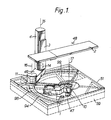
A patient support system for irradiation therapy or treatment simulation comprises a main arm 1 on a sub-floor mounted pivot 10 about a first vertical axis 17, which supports a further arm 49 rotatable about a second vertical axis 16. At the other end of the arm 49 a vertical pillar 4, pivotable about a third vertical axis 15, supports a vertically displaceable carriage 3 on which a patient support table top 2 is directly mounted. A control system is directed which enables x, y coordinate command values to control respective drives associated with the three vertical axes to position a patient quickly and accurately relative to the treatment isocentre.
The system requires only a shallow well while providing a large range of vertical lift. Furthermore, no sub-table x-y carriage is required increasing patient accessability.
Description
- The invention relates to a patient support system for irradiation therapy or treatment simulation, comprising a main supporting arm rotationally attached at one end to a structural support by a first support bearing so as to be rotatable about a first vertical axis fixedly located relative to the treatment isocentre, a patient support table top and interconnecting support means connecting the table top to the other end of the main supporting arm so that the table top can be displaced vertically and horizontally relative to the treatment isocentre.
- Radiation therapy involves directing a beam of high energy radiation such as hard x-rays or gamma rays from a suitable source, for example an isotope or a high energy x-ray tube using an electron accelerator, suitably a linear accelerator, at a selected region of the body of a patient in which malignant cells are present. A dosage is employed which is lethal to such cells, however, in order to minimise damage to other parts of the body, the dose applied to the surrounding tissue is reduced by rotating the direction of the irradiation beam about a central point called the treatment isocentre, which is located at or near the centre of the selected body region to be irradiated.
- For this purpose a source of high energy radiation is mounted in counterbalanced manner on a gantry so as to be capable of rotation about a horizontal axis through the isocentre. The source is heavily screened to reduce generally emitted radiation to a reasonably safe amount and the emergent irradiation beam is limited by a diaphragm which defines the boundaries of the region of the patient to be irradiated, in a manner such that radiation is generally directed radially towards the isocentre. The source and gantry assembly is consequently very massive and is normally fixed to the structure of the associated building. This means that the isocentre is fixed in space within the treatment room. It is therefore a requirement for a patient support system that it should be capable of supporting and displacing a patient in an accurate and reproducible manner so that any body region to be irradiated can be located at the isocentre and positioned relative to the scanning arc of the radiation source so that irradiation may be applied to the patient along selectable directions of incidence.
- A presently used form of patient support system of the kind referred to comprises a floor mounted relatively small turntable which is rotatable about a vertical axis usually through the isocentre and supports a radial arm extension the outer end of which is connected to a patient support table top by interconnecting support means in the form of a rotatably mounted pedestal base having an under table lift for vertical displacement and on the top of which is mounted a carriage assembly formed by a tandem arrangement of respective lateral and longitudinal horizontal displacement carriages, the table top being attached to the uppermost carriage. This form of patient support typically employs a form of scissors jack to provide the lift. Because of the relatively short stroke obtainable by such a jack and the need for a low minimum table height of about 70cm for the convenience of patient access to the table top, this results in a relatively low maximum lifting height of about 120cms. The maximum lifting height can be raised by the use of an underfloor pit. In some high energy installations the isocentre is even higher and a larger range of height adjustment can be provided using a hydraulic ram lift mounted on a more extensive turntable. This, however, requires the presence of a correspondingly deep underfloor pit to accommodate the ram housing resulting in higher installation costs and may not in some cases be structurally possible.
- A further disadvantage of the above described patient support system concerns the carriage assembly for providing the horizontal displacement of the table top in two dimensions since the carriages and associated parallel rails render the assembly bulky and heavy, and tend to restrict access to the patient.
- It is an object of the invention to provide an improved patient support system for irradiation therapy which can reduce these difficulties and which can be simple and convenient to operate in conjunction with computer controlled treatment and simulation equipment.
- In accordance with the invention there is provided a patient support system for irradiation therapy or treatment simulation, comprising a main supporting arm rotationally attached at one end to a structural support by a first support bearing so as to be rotatable about a first vertical axis fixedly located relative to the treatment isocentre, a patient support table top and interconnecting support means connecting the table top to the other end of the main supporting arm so that the table top can be displaced vertically and horizontally relative to the treatment isocentre, characterised in that the interconnecting support means comprise a further supporting arm rotationally attached at one end to said other end of the main supporting arm by a second support bearing so as to be rotatable about a second vertical axis, and vertical support means rotationally attached to the other end of the further supporting arm by a third support bearing so as to be rotatable about a third vertical axis, the patient support table top being attached to supporting carrier means, and the vertical support means includes means for locating and vertically displacing the supporting carrier means.
- The vertical support means preferably comprises a single vertical supporting pillar of rigid closed box construction, the supporting carrier means preferably comprises a vertically displaceable carriage of rigid box construction and the means for locating and vertically displacing the supporting carrier means preferably include two longitudinal guide tracks which are rigidly mounted adjacent one another with their lateral directions at a mutual angle preferably at right angles, on a supporting surface having a correspondingly angled open V-shaped transverse section, which is rigidly connected to the vertical supporting pillar, the vertically displaceable carriage being provided with bearing members which engage the corresponding longitudinal guide tracks so as to locate and support the carriage in a vertically displaceable manner relative to the pillar. The V-shaped supporting surface can be formed by an outer wall surface of the pillar, and the means for vertically displacing the supporting carrier can comprise a motor driven rotatable screw threaded shaft mounted in a thrust bearing supported by the vertical supporting pillar, said shaft engaging a corresponding nut attached to the vertically displaceable carriage.
- The main supporting arm can be located entirely below the floor of a treatment room and an arcuate aperture can be provided in the floor surface to accommodate connecting means connecting said other end of the main supporting arm to one end of the further supporting arm which is situated above the floor via the second support bearing, the arcuate aperture being covered by a flexible cover strip which is passed through a passageway formed in the connecting means. The flexible cover strip can comprise a plurality of adjacent transversely arranged load-bearing strips or segments flexibly linked to one another, and the inner and outer sides of the arcuate aperture are each preferably provided with a supporting ledge arranged so that each segment can be supported at each end by a corresponding ledge with the upper surface of the flexible cover strip flush with the surface of the floor. A smooth-walled duct and/or an arrangement of bearing rollers can be disposed along the path of the flexible strip through the passageway so as to guide the flexible strip past connecting supports forming the connecting means.
- Alternatively the main supporting arm can comprise a first arm portion attached to the first support bearing and supporting a turntable surface level with the surface of the floor, and a further arm portion extending outwardly above the floor level from the outer part of the turntable surface, the second support bearing being attached to the outer end of the further arm portion.
- Preferably the first, second and third support bearing and the means for vertically displacing the supporting carrier means are each provided with corresponding motor drives suitably employing electric drive motors and associated output shaft angular position and velocity sensing means, control means being provided for controlling the motor drives in response to the outputs of the associated sensing means and to corresponding position demand values resulting from instructions provided by the operator and respective motor drives arranged to provide corresponding angular displacements about the first, second and third vertical axes can be controlled by computer means. The computer means can comprise one or more microprocessors and the motor drives can employ d.c. electric motors. Preferably electric motor drives associated with the first, second and third support bearings, include reduction gearing employing a harmonic drive, for example a strain wave gear arrangement.
- Embodiments of the invention will now be described by way of example, with reference to the accompanying drawings of which:-
- Figure 1 is a perspective view, partly cut away, illustrating diagrammatically a patient support system in accordance with the invention,
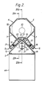
- Figure 2 is a cross section of a vertical supporting pillar employed in Figure 1,
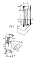
- Figure 3 is a disassembled perspective diagram illustrating the parts of Figure 2,
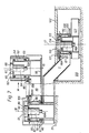
- Figure 4 is a longitudinal section, partly cut away of the vertical support pillar of Figure 1,
- Figure 5 is a diagrammatic vertical section illustrating part of the supporting arm assembly of Figure 1,
- Figure 6 is a diagrammatic vertical section of a connecting bearing taken at right angles to Figure 5,
- Figure 7 is a diagrammatic vertical section illustrating part of the supporting arm assembly of a modified patient support system in accordance with the invention.
- Figure 8 is a diagram illustrating geometrically the control parameters,
- Figure 9 is a diagram illustrating a forward transform factor field, and
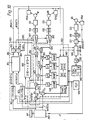
- Figure 10 is a block diagram illustrating a control arrangement for the patient support system shown in Figure 1.
- Reference will now be made to Figure 1 which illustrates a patient support system for irradiation therapy or treatment simulation in accordance with the invention. A main supporting
arm 1 is rotationally attached at one end by means of a first support bearing 10, suitably two spaced heavy duty single race ball bearings, to a structural support in the form of anunderfloor mounting frame 47 fixed to the substructure of thefloor 51 of the treatment room in ashallow well 59, so as to be rotatable about a firstvertical axis 17. Theaxis 17 can, if desired, pass through thetreatment isocentre 48 of an associated counterbalanced gantry-mounted high-energy irradiation source (not shown), but will in any event be fixed relative thereto since the irradiation source gantry will also be fixedly attached to the structure of the treatment building. Apatient support 2 is connected to the other end of the main supportingarm 1 by interconnecting support means 4, 49 , so that thetable top 2 can be displaced vertically and horizontally relative to thetreatment isocentre 48. - In accordance with the invention the interconnecting support means comprise a further supporting
arm 49 rotationally attached at one end to the unsupported end of the main supportingarm 1 by means of a second support bearing 11, suitably in the form of two spaced single race ball bearings, so as to be rotatable about a secondvertical axis 16, and vertical support means in the form of a single vertical supportingpillar 4 rotationally attached to the other end of the further supportingarm 49 by a third support bearing 14, suitably in the form of two spaced single race ball bearings, so as to be rotatable about a thirdvertical axis 15. The patientsupport table top 2 is attached to supporting carrier means in the form of a verticallydisplaceable carriage 3, and thepillar 4 includes means for locating and vertically displacing thecarriage 3 as will now be described with reference to Figures 2, 3 and 4. - Figure 2 is a horizontal cross-section through the
pillar 4 and thecarriage 3 and illustrates one form of vertically displaceable coupling therebetween. Thepillar 4 is formed as a rigid closed box construction, suitably of shaped panels of sheet steel hole welded together at intervals, so thatside walls pillar 4, and a transverse stiffening member, e.g. atop plate 34 orouter bearing sleeve 52, (Figure 4) hole welded at each end, and if desired, also at intermediate positions, e.g. abulkhead plate 43, for additional rigidity. The verticallydisplaceable carriage 3 is of rigid box construction being formed of a V-shaped wall 13 adjacent thepillar 4 stiffened by transverse plates hole welded at intervals along its length. Further stiffening is provided by the tabletop connection socket 44 hole welded across the open side. The open side of the carriage is closed by afront plate 46 which can be removable for access to the interior, to form a closed box structure of further improved torsional rigidity. - In order to locate the
carriage 3 horizontally, thepillar 4 is provided with guide means formed by twolongitudinal guide tracks pillar 4, and in the present example comprises theouter wall surface 6 of thepillar 4. In the present example theguide tracks steel stripes wall 6. Thecarriage 3 is provided with bearing members in the form ofrollers 12 on the outer side of thewall surface 13. In operation, therollers 12 are situated in the guide recesses so as to engage the respective pairs of facing side faces of thestrips carriage 3 in a vertically displaceable manner relative to thepillar 4. Further horizontal support is provided byrollers 40, shown in the disassembled perspective diagram of the cooperating sides of thepillar 4 and thecarriage 3 in Figure 3, which bear, in operation, on the outer surfaces of the respectiveouter strips wall surface 13 or the end face of thecorresponding rollers 12, and the surface of thestrips wall 6 and also to ensure that thetable top 2 is restrained from swinging about a vertical axis passing through thepillar 4. - Figure 4 is a vertical section partly cut away, illustrating the means for vertically displacing the supporting carrier. The
carriage 3 is supported and displaced in a vertical direction by means of a motor driven rotatable screw threadedshaft 23 mounted in a thrust bearing 24 supported by a supportingplate 25 forming the upper bulkhead of thebox pillar 4, theshaft 23 engaging a corresponding nut 22 attached to thecarriage 3. The threadedshaft 23 is driven via a toothed belt 28 which engages atoothed pinion 29 mounted on theshaft 23, and a furthertoothed pinion 32 on the output shaft of thereduction gear train 31 of a drive motor assembly, suitably employing anelectrical drive motor 30. Rotation of theshaft 23 and hence the height of thetable top 2, is sensed by anangular position sensor 33A driven by a further toothed belt 35 which also engages thetoothed pinion 29 on theshaft 23 and anangular velocity sensor 33V mounted on the shaft of theelectrical drive motor 30. A fail-safe brake 36 is fixed to the end of theshaft 23 to hold the vertical table position steady and anidler safety nut 37 is arranged under the nut 22 to operate normally under no-load conditions to act as a safety stop if the thread of the support nut 22 should fail or when a low friction recirculating ball arrangement is used, if the ball cage should burst. - In order to allow for variations in alignment between the supports of the nut 22, the thrust bearing 24 and the threaded
shaft 23 as thecarriage 3 is displaced vertically on thepillar 4, the nut 22 and the thrust bearing 24 are respectively attached to thecarriage 3 and to the supportingplate 25, by a cardanic assembly formed byintermediate suspension plates pillars 76 located on the supportingplate 25, are diametrically spaced about the axis of theshaft 23 to support the upperintermediate plate 27 via associatedbearing projections 39 so that it can tilt about a corresponding diametric transverse axis through theprojections 39. The thrust bearing 24 is connected to the upperintermediate plate 27 by two bearingprojections 39 which are diametrically spaced about the axis of theshaft 23 in a further transverse direction at right angles to the first mentioned diametric transverse axis so that the thrust bearing 24 is thereby enabled to tilt both about a transverse axis directed along the further transverse direction and about the first mentioned transverse axis. Twopillars 77 located on atransverse plate 81 forming part of thecarriage 3, are diametrically spaced about the axis of theshaft 23 and support the lowerintermediate support plate 26 by means of corresponding relativelysmall bolts 69 so that the assembly including theplate 26 can flex slightly and therefore tilt about a corresponding diametric transverse axis through the points of attachment. A flange on the nut 22 is connected to theplate 26 by two bearingprojections 39 similarly diametrically spaced about theshaft 23 in a transverse direction at right angles to that of thebolts 69 to enable the nut to tilt about either transverse direction relative to thecarriage 3. - In order to protect and to hide the
guide tracks shaft 23, a respective roller blind 41, 42 is fitted to the upper and lower surfaces of thecarriage 3 to extend to the top and bottom of thepillar 4, respectively. The patientsupport table top 2 is attached to thecarriage 3 by means of a connectingbracket 44 which is provided with a releasable table connection means so that different table tops may be substituted e.g. for radiotherapy and for treatment simulation. - The
carriage 3 is supported so as to prevent a turning displacement about a horizontal axis due to the loading caused by thetable top 2 and the additional weight of a supported patient, by the presence of tworollers 12 spaced apart in the vertical direction in each of the guide tracks 8, 9. In the arrangement shown in Figure 1, the resultant centre of gravity of the patient and thetable top 2 will lie to the right of thepillar 4. Thus in theright hand track 8 theupper roller 12 will bear against thefront strip 8 and the lower roller will bear against theinner strip 9. The resultant centre of gravity will also usually lie to the right of the normal to the centre of theleft hand track 9 and consequently theupper roller 12 in that track will bear against theinner strip 20 and the lower roller will bear against theouter strip 21. Clearly the diameters of therollers 12 must be slightly less than the spacing between the facing surfaces of the corresponding pair ofstrips roller 12 is replaced by a pair of adjacent rollers each of whose diameter is less than the spacing between the facing surfaces of the guide. To reduce free movement in the coupling, that roller of each pair which does not bear the load torque due to the table and patient, is mounted on a prestressed spring mounting which urges the roller into contact with the adjacent guide surface while the load bearing roller is journalled on a shaft which is rigidly fixed to thecarriage 3. In this way a predetermined negative loading torque would need to be applied to thecarriage 3 before any free play could occur. - This and other forms of vertical supporting pillar are described in our copending U.K. Patent Application No. 8630411 and the contents thereof are to be regarded as disclosing suitable forms of and alternatives to the
pillar 4 herein described, with respect to the present patient support. - The lower end of the
pillar 4 is rigidly attached to the outercylindrical member 52 of the third support bearing 14, suitably by hold welding. Thecylindrical member 52 thus forms the transverse stiffening member for the lower end of thepillar 4. The innercylindrical member 54 of the third support bearing 14, is rigidly fixed, suitably by hole welding, to theload bearing beam 58 of thefurther support arm 49. Thecylindrical bearing members races - Rotation of the
pillar 4 relative to the further supportingarm 49, about the thirdvertical axis 15, is effected by means of a motor drive suitably comprising anelectric motor 64 withreduction gear box 65 driving aharmonic drive 66 connected between the inner and outercylindrical bearing members - One form of harmonic drive is described in US Patent No. 2,906,143 which discloses various examples of strain wave gearing. In one example, an elliptical strain inducing element having an eccentricity e only slightly different from unity, is centrally mounted on an input shaft driven by, for example, a motor, and is disposed in sliding contact with, or via a ball race to reduce friction, a surrounding elastically deformable first annular toothed member with outwardly facing teeth, attached to one side of the output drive. A rigid second annular toothed member with inwardly facing teeth, is attached to the other side of the output drive which is rotatable relative to the first side thereof, and surrounds the first member at a radial distance such that the outwardly facing teeth on the first member are strained outwardly by the elliptical element within two diametrically opposed angular regions, into contact with the inwardly facing teeth of the second member. The respective numbers of teeth on the two annular members are made slightly different, for example 198 and 200 on the inner and outer members, respectively. Thus in this example, each revolution of the input shaft will displace one side of the output drive relative to the other side thereof by 1/100th of a revolution giving a reduction ratio of 100:1 but greater reductions can be provided by employing a larger number of teeth on each member while maintaining the same difference in the numbers of teeth.
- The
harmonic drive 66 shown in Figure 4, preferably employs a form of the strain wave gearing arrangement briefly described above. The drive housing is thus constructed in twoparts vertical axis 15. Onepart 67 is secured to the innercylindrical member 54 of the third support bearing 14 and to one of the annular members so as to form one side of the output drive of the strain wave gear. Theother part 68 is secured to the outercylindrical member 52 of thebearing 14 and to the other annular member of the drive so as to form the other side of the output drive. It does not matter which annular member is connected to whichpart motor 64 and thegearbox 65 drives the input shaft and hence the strain inducing element of the harmonic drive. The housing of themotor 64 and thegearbox 65 is connected to thepart 67 for convenience, but could equally well be connected to theother part 68 if desired. - Many advantages relating to the strain wave gearing arrangement are listed in the US patent but particularly relevant to the present application is that the output torque applied between the two
sides members - Other forms of harmonic drive can be employed for the
drive 66. The aforementioned US Patent also illustrates a three lobed strain inducer which has self-centring properties relative to the two sides of the output drive. However, it is made clear that the stresses in a three lobed inducer gear are much greater than in a gear employing the two lobed (elliptical) inducer hereinbefore described for the same output loading, and the three lobed arrangement is therefore less suited to the present application. More traditional forms of harmonic drive include that employing a rigid first annular member mounted on an eccentric circular cam driven by the input shaft, and frequently employed in cyclometer mechanisms inter alia, or one of the various forms of wobble gear mechanisms some of which use bevel gears rather than cylindrical arrangements. These latter forms, however, suffer the disadvantages that the output drive is in general unbalanced about the central axis, that the load will be distributed less evenly over a smaller proportion of the teeth, and that they are prone to backlash since both meshed members are rigid. The preferred strain wave gearing arrangement using an elliptic strain inducer on the other hand provides a diametrically balanced drive torque between the two elements of the output drive. - The relative angular displacement of the
pillar 4 about the thirdvertical axis 15 relative to the further supportingarm 49 is sensed by anangular position sensor 83A which is mounted on the further supportingarm 49 and is driven via atoothed belt 85 the ends of which are attached to a point on a circumferential region at the lower end of the outercylindrical member 52 of the third support bearing 14. Anangular velocity sensor 83V is conveniently included on the shaft of thedrive motor 64. - Referring to Figure 5, the second support bearing 11 which connects the unsupported end of the main supporting
arm 1 to that end of the further supportingarm 49 which is distant from thepillar 4, is basically similar in construction to that of the third support bearing 14. Thus the bearing comprises inner and outer coaxialcylindrical bearing members races 88 for relative angular displacement about the secondvertical axis 16, and rigidly connected to respective output driveparts harmonic drive gearbox 91, preferably formed as in the case of thedrive 66 by a diametrically induced strain wave gearing arrangement, which together with a motor, suitably anelectric drive motor 92 provided with anangular velocity sensor 104V and areduction gearbox 93 form a motor drive for angularly displacing thearm 49 relative to themain arm 1 about the secondvertical axis 16. Theload bearing beam 58 of thearm 49 is rigidly attached, suitably by hole welding, to the outer bearingmember 87. - The relative angle between the
arms sensor 104A mounted on thebeam 58 and driven via atoothed belt 105 from the upper rim of theinner bearing member 86 via a slot in the outer bearingmember 87. - The main supporting
arm 1 is located below the surface of thefloor 51 of the treatment room and anarcuate aperture 94 is provided in the floor surface to accommodate connecting means in the form of a supportingextension 95 to theinner bearing member 86, which is rigidly attached to the main supportingarm 1 suitably by hole welding. Thearcuate aperture 94 in thefloor 51 is covered by aflexible cover strip 96 which is passed through apassageway 97 through the supportingextension 95. - The
flexible strip 96 is generally arcuate in plan view as can be seen from Figure 1, and in order to provide a secure surface for standing on, thestrip 96 comprises a plurality of transversely arranged load-bearing segments, virtually strips, 100, flexibly linked to one another, and the inner and outer sides of thearcuate aperture 94 are each provided with a supportingledge 98 fixedly attached to a floor-supportingframe 99, and arranged so that each segment 100 resting thereon is supported at each end by a correspondingledge 98 with the upper surface of theflexible cover strip 96 flush with thesurface 51 of the floor. The segments 100 can be made of any suitable load-bearing material having sufficient resistance to wear, for example hardwood or metal such as duralumin or steel, suitably pressed from sheet material, or can be a form of high strength high impact resistance plastic formed by injection moulding. The strips can be flexibly linked by a continuous band attached by a suitable adhesive either to the bottom or, preferably, to the top surface of the segments 100. The band may be of plastic reinforced by high tensile flexible filaments or of a suitable woven fabric preferably with a coated exposed surface. An alternative form of construction is to link each segment 100 to its neighbour by means of a hinge whose pivotal axis is directed radially from the firstvertical axis 17, to form a hinged track. In this case the upper surface of each segment 100 can be formed as a non-slip flooring surface, or a suitable covering band applied with adhesive provided the effective pivotal axis of the hinge is sufficiently close to the upper surface. - The
passageway 97 formed in the supportingextension 95 preferably includes a smoothwalled duct 102 to guide theflexible strip 96 past the supporting connectingportions 103 of the supportingextension 95, which must join with sufficient strength the lower part of theextension 95 which is attached to the main supportingarm 1 and is accommodated in thearcuate slot 94, to theinner bearing member 86 so that thefurther arm 49, thepillar 4, thetable top 2 and the patient, when present, are securely supported thereby. As an alternative or in combination with theduct 102, bearingrollers 106, indicated by dashed outlines, are arranged in pairs, with one roller on each side of the centre of thestrip 96, at intervals along the path of theflexible strip 96 through thepassageway 97 for guidance purposes. Some or all of therollers 106 may, if desired, be actively driven by electric motors, preferably in response to an angular displacement of themain arm 1 about the firstvertical axis 17, to assist the passage of the vertically displaced portion of thestrip 96 past the supportingextension 95. - The first support bearing 10 which supports the
main arm 1, is of similar construction to that of the second andthird support bearings bearing 10 comprises inner and outer coaxialcylindrical bearing members race ball bearings 110 for the angular displacement of themain arm 1 about the firstvertical axis 17. Theinner bearing member 108 is rigidly fixed to theunderfloor mounting frame 47 which is itself attached to the substructure of thefloor 51 in thewell 59. Theouter bearing member 109 is fixedly attached to thearm 1, suitably by hole welding. Rotary displacement of thearm 1 about theaxis 17 is effected by means of a motor drive suitably comprising anelectric motor 111 provided with avelocity sensor 116V, areduction gearbox 112 and aharmonic drive gearbox 113. The harmonic drive preferably comprises a strain wave gearing arrangement using a symmetrical two lobed (elliptical) strain inducer as hereinbefore described and the respective output driveparts cylindrical bearing members arm 1 about the firstvertical axis 17, is sensed by asensor 116A mounted on themain arm 1 and driven via atoothed belt 117 attached at both ends to respective points on an upper rim of theinner bearing member 108 via a slot-like aperture in theouter bearing member 109. Because of the stresses involved, the surface of the teeth in the harmonic drive must be suitably hardened without adversely affecting the flexibility of the inner annular output drive component. - The patient support system illustrated in Figures 1, 5 and 6, requires a fairly extensive under-floor well 59 to accommodate the main supporting
arm 1, and also some form of displaceable cover for thearcuate aperture 94 which is necessary to allow the supportingextension 95 to pass from the supporting end of themain arm 1 below floor level so as to support thebearing 11, thearm 49 and thepillar 4 which are all situated above the floor. Furthermore an extensive supportingframework 99 has to be provided to support a floor surface over the well 59 on either side of thearcuate aperture 94. If it is not possible for structural or economic reasons to provide a well of sufficient size, a modified form of patient support system may be provided in accordance with the invention and as illustrated diagrammatically in Figure 7, in which the main supportingarm 1 comprises a first arm portion 120 which is fixedly attached, suitably by hold welding, to the outercylindrical bearing member 109 of the first support bearing 10, and is situated below thefloor surface 51, and a further arm portion 121 extending above thefloor surface 51. The first arm portion 120, the first support bearing 10 and a mountingframe 127 to which the innercylindrical bearing member 108 is fixedly attached, suitably by hole welding, are all accommodated in a relatively compactcylindrical well 129, and the first arm portion and the top of theouter bearing member 109 are attached to and support aturntable 122 which forms a covering and supporting floor surface over the well 129. The further arm portion 121 extends outwardly above the floor level from the outer part of the turntable surface and can be formed as an integral extension of the first arm portion 120. The outer end of the further arm portion 121 is rigidly attached to the inner cylindrical bearingmember 86 of the second support bearing 11 and is arranged so that thearms turntable 122 will turn with themain arm 1 and the further arm portion 121 above the floor will form a mobile obstruction within the working area around the patient support table top. - In both embodiments it would be usual to provide touch sensitive switching members especially at floor level for operating an electrical cut out for the drive motors should a collision occur with the operator or other obstruction during displacement, and such collisions would be expected to be more frequent in the arrangement of Figure 7.
- The relative lengths of the main and further supporting
arms arm 49 is required to perform to locate any point along the table top and hence in a patient, at the treatment isocentre for the operational range of values for the angle alpha of say -70 degrees to +70 degrees, can be achieved with a reasonable angular displacement of about 90 degrees about the secondvertical axis 16. The length of the main supportingarm 1 in combination with the length of thefurther arm 49, is preferably arranged so that thepillar 4 can be readily maintained just clear of the region which is swept by the head of the high energy radiation source, usually a linear accelerator, or of the simulation radiographic head and image section, during a normal irradiation treatment or simulation. - Suitable forms of control arrangement will now be considered which enable the treatment region of a patient supported by the
support table top 2 to be readily positioned in the treatment zone about the isocentre in response to an operator command or a suitable stored treatment program. - Each of the motor drives which in the present example are assumed to be actuated by electric drive motors, can be arranged as a form of set-point servo in which a set-point input value representing a vertical position Z in the case of the
motor drive support bearings vertical axes carriage 3 in response to the associated position sensing means 116A, 104A, 83A and 33A, and to set-point demand values corresponding to demand position commands which the operator can provide directly as an instruction, for example via a keypad, or which can be generated by computer means for example from a therapy treatment program. - Figure 8 is a diagram which illustrates the relationship between the components of the patient support system of Figure 1 and those geometrical parameters relating to a horizontal plane which are employed for the control of the relevant motor drives and for defining a dynamic treatment program relative to the isocentre. It is usual in irradiation therapy to define the patient position in a cartesian coordinate system with the origin X0, Y0, Z0, at the isocentre of the high-energy source gantry. It is also usual to define an angle alpha as the angle between the longitudinal axis of the patient
support table top 2 and the rotation axis of the gantry which latter is also directed along the X-axis. The Z-axis is the vertical axis. The patient position is taken as a specified point, usually at or near the centre of a region in the patient which is to receive treatment, and is indicated by the reference point a in Figure 8. - The horizontal coordinates of the first
vertical axis 17 are X1, Y1, and can if desired, lie at the origin X0, Y0 although this is not essential since a constant offset of (X1-X0), (Y1-Y0), can be simply applied to any calculations in the X-Y plane. The angular position phi1 of the main supportingarm 1 is measured anticlockwise from the X-axis and the secondvertical axis 16 is spaced a distance r1 from the first. The angular position phi2 of the further supportingarm 49 is measured anticlockwise from an in-line position relative to themain arm 1. The thirdvertical axis 15 is spaced a distance r2 from thesecond axis 16, and the angular position phi3 of the longitudinal axis of the table top is measured from a direction parallel to thearm 49 in an anticlockwise direction as indicated. The coordinate positions of the second and third vertical axes in the X-Y plane are identified as X2, Y2, and X3, Y3, respectively, and will vary with the horizontal adjustment of the table top relative to the first vertical axis X1, Y1 which is permanently fixed. - The reference point a in the treatment region of a patient located on the
table top 2, is a horizontal radial distance r3 from the thirdvertical axis 15 at the point X3, Y3, and the connecting line r3 is inclined at an angle beta measured in an anticlockwise direction about the thirdvertical axis 15 from the direction of the longitudinal axis of the table top. It should be noted that while r1 and r2 are fixed quantities determined by the apparatus, the values of r3 and beta will vary in an arbitrary manner from one treatment to another and must be determined by the system each time a patient is placed on thetable top 2. This can be carried out by manually controlling the support system until the point a, indicated in practice by a visible mark applied to the upper surface of the patient, coincides with the origin X0, Y0 as indicated optically by a light beam projector (not shown) in the high-energy treatment head which latter is orientated on the gantry (not shown) to project the light beam vertically. In this position of the patient, the X and Y coordinates of the point X3, Y3 representing the thirdvertical axis 15, are determined from the measured values of the angular positions phi1 and phi2 provided by theangular position sensors vertical axis 17. From the geometry of the arrangement and the operational requirement that the table axis must be inclined by a preset angle alpha which can be zero, to the x-axis, the angle phi3 must be maintained, e.g.by set-point servo control, so that the sum of phi1, phi2 and phi3 always equals alpha (+ 360 degrees). From this data it is a simple process to compute the values of the distance r3 and the angle beta forexample using equations vertical drive motor 30 is energised so as to make a further optical mark applied to the side of the patient coincide with the projected reference beam. The value which is then read out from theposition sensor 33A, is stored as the position of the origin Z0 for the subsequent treatment or simulation. - The coordinated control of the patient support system in accordance with the invention is preferably arranged so that the respective electric motor drives employing the
motors vertical axes - A direct X-Y to
angle phi - The reverse coordinate transformation which enables the actual horizontal cartesian coordinates Xa(act), Ya(act) of the patient reference point a to be calculated from present angular values phi1(act), phi2(act) and phi3(act) measured by the
data sensors equation - As hereinbefore mentioned in relation to the setting-up procedure and as shown by
equation 3, themotor drive - The transformation defined by
equations equations equations equations - One form of coordinated control arrangement for a three-axis patient support system which forms the subject matter of our co-pending U.K. Patent Application (PHQ87004) is illustrated diagrammatically in Figure 10 (which is partly a flow diagram for the processing of data) in which most of the blocks represent arithmetical operations which can be carried out digitally by a computer or microprocessor in a programmed sequence related to a data sampling cycle controlling the aquisition of angular position data and programmed set-point demand values. Alternatively some or all of the blocks can be implemented by corresponding hardware elements.
- The angular displacements phi1, phi2 and phi3 are effected by servo systems represented by
blocks servos analog converter servo 133 is a set-point servo which is arranged to make phi3(act) measured by thedata sensor 83A, equal to the difference between alpha and the sum of phi1(act) and phi2(act) obtained by a computing process indicated by theblock 136. The result from 136 is applied with the output from 83A to adifferencing process 137 to detect any error Ephi3 in accordance withequation 17 in which the measured actual values are employed. The actual values and theprocesses analog converter 138 to provide the analog error drive signal for theservo 133. The momentary value representing the angle alpha, block 139, is stored at an available location in memory and may be a value provided by the operator at the start of an operation, or may be the present value from a sequence of values forming part of a treatment or simulation control program. The general control and operating system is indicated by theblock 140, and amanual input keyboard 141 is provided. Thesystem 140 can comprise a small general purpose computer or can be made up of one or more microprocessor based systems. - The dashed
line boundary 142 indicates the processes involved in the nulling servo arrangement, by means of which set-point coordinate values Xa(setp) and Ya(setp) demanded via thecontrol system 140 by the operator or by a treatment or simulation program, are converted into corresponding angular positions phi1 and phi2 by theopen loop servos - A main computing process in this conversion is the reverse transformation calculation represented by the
block 143. The actual values phi1(act) and phi2(act) are sampled from theposition sensors equations memory locations equations - The respective actual values Xa(act), Ya(act) are subtracted from the corresponding set-point demand values Xa(setp) and Ya(setp) provided by the
control system 140, by a differencing process indicated by 146 and 147, respectively, to provide error quantities EX, EY representing the magnitude and sign of the cartesian error components. Before such error values can be applied to form a drive signal to theangular drive servos servo equations blocks blocks equations - The differential coefficients ought strictly to relate to the coordinates and related angles represented by the set-point demand values Xa(setp), Ya(setp), however, when the servo errors are small and the system is following a series of closely adjacent values, it is sufficient to use differential coefficients calculated from the actual values of phi1 and phi2 since the relevant coefficients will tend towards the correct values as the null balance point is approached.
- Calculation of the differential coefficients does not add significantly to the data processing time since the values of the sine and cosine terms will already have been derived for the
basic transformation equations equations equations - Although the nulling servo arrangement described so far can function correctly when the set-point demand values applied are relatively close to the actual position values, difficulties arise when a large difference in position values is presented, for example as the result of a manual input command or an initial step or a large change in a treatment pattern. Thus it will be apparent from
equations outline 160 which includes a coarse look-up table represented by theblock 161, and which provides substitute drive signals to theservos - The look-up table 161 comprises a two-dimensionally organised storage facility, suitably implemented by a ROM or an EPROM matrix store, and can be addressed in accordance with the more significant digits representing the quantities X(1)3(setp) and Y(1)3(setp) derived from the values Xa(setp), Ya(setp) by subtracting the origin offset X1, Y1 and the patient reference point offset X(3)a, Y(3)a as indicated by
blocks store 161 then outputs respective coarse values phi1c and phi2c which have been computed and adjusted on manufacture to provide initial demand angle settings for theservos position sensors comparison process 166 in which the absolute values of EX and EY are compared with a predetermined value k and when either or both exceed that value both switch processes 167 and 168 are changed over so that the error drive signals input to theservos A converters servos switches nulling servo 142 operates as hereinbefore described. - The field of X(1)3, Y(1)3 values represented by the table 161 must, of course be more extensive than the required displacement field for the patient reference point a about the isocentre, and which could for example be about 1m square, because allowance must be made for the range of variation to be expected in the patient reference point offset X(3)a, Y(3)a, and this might further amount to about 1m square. Thus the maximum field required for the distances X(1)3, Y(1)3 represented in the look-up table 161 would be about 2m square and both dimensions can each be satisfactorily divided into fifteen equal intervals giving a grid of 256 spot values. If the corresponding angles phi1 and phi2 are each coarsly represented by one byte (eight bits) at the related addresses, only about 1K of storage will be required, and the angles can be represented to within about 1.5 degrees.
- The value of k employed in the
comparison process 166 must be selected so as to ensure that for all the stored pairs of spot values of phi1 and phi2 in the look-up table, both EX and EY will fall below the value k well before both theservos nulling servo arrangement 142 to complete the positioning process without difficulty. - Modifications and alternatives to the control arrangement illustrated and described with reference to Figure 10, can be employed. Thus, in determining the appropriate polarities for the cartesian error components EX and EY which are to be combined to form the angular error (drive) signals Ephi1 and Ephi2, the partial differential coefficients generated from the actual values of the angular positions phi1 and phi2, can be replaced by data relating to the appropriate polarities which is stored in a look-up table organised in a similar manner to the table 161. For example, the quantities X(1)3(setp) and Y(1)3(setp) can be employed to address a stored set of polarity coefficients, e.g. -1, 0, +1, relating to EX and EY, and to Ephi1 and Ephi2 near the corresponding null point of balance at the demand values X(1)3(setp) and Y(1)3(setp). The coefficient zero may be required when a respective quadrature control condition for either EX or EY lies within the expected balancing range. Preferably such a look-up table would also store coarse demand values for phi1 and phi2 as in the case of table 161, for use in a similar manner when either or both cartesian error values are large.
Claims (15)
1. A patient support system for irradiation therapy or treatment simulation, comprising a main supporting arm rotationally attached at one end to a structural support by a first support bearing so as to be rotatable about a first vertical axis fixedly located relative to the treatment isocentre, a patient support table top and interconnecting support means connecting the table top to the other end of the main supporting arm so that the table top can be displaced vertically and horizontally relative to the treatment isocentre, characterised in that the interconnecting support means comprise a further supporting arm rotationally attached at one end to said other end of the main supporting arm by a second support bearing so as to be rotatable about a second vertical axis, and vertical support means rotationally attached to the other end of the further supporting arm by a third support bearing so as to be rotatable about a third vertical axis, the patient support table top being attached to supporting carrier means, and the vertical support means includes means for locating and vertically displacing the supporting carrier means.
2. A patient support system as claimed in Claim 1, characterised in that the vertical support means comprises a single vertical supporting pillar of rigid closed box construction, the supporting carrier means comprises a vertically displaceable carriage of rigid box construction and the means for locating and vertically displacing the supporting carrier means include two longitudinal guide tracks which are rigidly mounted adjacent one another with their lateral directions at a mutual angle to one another, on a supporting surface having a correspondingly angled open V-shaped transverse section, which is rigidly connected to the vertical supporting pillar, the vertically displaceable carriage being provided with bearing members which engage the corresponding longitudinal guide tracks so as to locate and support the carriage in a vertically displaceable manner relative to the pillar, the mutual angle between the guide tracks being such in cooperation with the bearing members that the carriage is retained and located horizontally relative to the pillar.
3. A patient support system as claimed in Claim 2, characterised in that the mutual angle between the lateral directions of the guide tracks is a right angle.
4. A patient support system as claimed in Claim 2 or Claim 3, characterised in that the V-shaped supporting surface is formed by an outer wall surface of the vertical supporting pillar.
5. A patient support system as claimed in any one of Claims 2, 3 or 4, characterised in that the means for locating and vertically displacing the supporting carrier means include a motor driven rotatable screw threaded shaft mounted in a thrust bearing supported by the vertical supporting pillar, said shaft engaging a corresponding nut attached to the vertically displaceable carriage.
6. A patient support system as claimed in any one of the preceding claims, characterised in that the main supporting arm is located below the floor of a treatment room and an arcuate aperture is provided in the floor surface to accommodate connecting means connecting said other end of the main supporting arm to one end of the further supporting arm which is situated above the floor via the second support bearing, the arcuate aperture being covered by a flexible cover strip which is passed through a passageway formed in the connecting means.
7. A patient support system as claimed in Claim 6, characterised in that the flexible cover strip comprises a plurality of transversely arranged load-bearing segments flexibly linked to one another, and the inner and outer sides of the arcuate aperture are each provided with a supporting ledge arranged so that each segment can be supported at each end by a corresponding ledge with the upper surface of the flexible cover strip flush with the surface of the floor.
8. A patient support system as claimed in Claim 6 or Claim 7, characterised in that the passageway formed in the connecting means includes a smooth-walled duct to guide the flexible strip past supporting interconnections forming part of the connecting means.
9. A patient support system as claimed in any one of Claims 6 to 8, characterised in that bearing rollers are arranged along the path of the flexible strip through the passageway formed in the connecting means so as to guide the flexible strip past supporting interconnections forming part of the connecting means.
10. A patient support system as claimed in any one of Claims 1 to 5, characterised in that the main supporting arm comprises a first arm portion attached to the first support bearing and supporting a turntable surface level with the surface of the floor, and a further arm portion extending outwardly above the floor level from the outer part of the turntable surface, the second support bearing being attached to the outer end of the further arm portion.
11. A patient support system as claimed in any one of the preceding claims, characterised in that the first, second and third support bearings and the means for vertically displacing the supporting carrier means are each provided with corresponding motor drives and associated output shaft angular position and velocity sensing means, control means being provided for controlling the motor drives in response to the outputs of the associated sensing means and to corresponding position demand values resulting from instructions provided by the operator.
12. A patient support system as claimed in Claim 11, characterised in that the motor drives are provided with electric drive motors.
13. A patient support system as claimed in Claim 12, characterised in that at least one of the electric motor drives includes reduction gearing employing a harmonic drive arrangement.
14. A patient support system as claimed in Claim 13, characterised in that the harmonic drive is a strain wave gear arrangement employing a two lobed strain inducing element.
15. A patient support system for irradiation therapy or treatment simulation, substantially as herein described with reference to Figures 1 to 6 or Figures 1, 2, 3, 4 and 7 of the accompanying drawings.
Applications Claiming Priority (2)
| Application Number | Priority Date | Filing Date | Title |
|---|---|---|---|
| GB8706152 | 1987-03-16 | ||
| GB878706152A GB8706152D0 (en) | 1987-03-16 | 1987-03-16 | Patient support system for radiotherapy |
Publications (1)
| Publication Number | Publication Date |
|---|---|
| EP0283083A1 true EP0283083A1 (en) | 1988-09-21 |
Family
ID=10614010
Family Applications (1)
| Application Number | Title | Priority Date | Filing Date |
|---|---|---|---|
| EP88200439A Withdrawn EP0283083A1 (en) | 1987-03-16 | 1988-03-08 | A patient support system for radiotherapy |
Country Status (4)
| Country | Link |
|---|---|
| US (1) | US4885998A (en) |
| EP (1) | EP0283083A1 (en) |
| JP (1) | JPS6485675A (en) |
| GB (1) | GB8706152D0 (en) |
Cited By (10)
| Publication number | Priority date | Publication date | Assignee | Title |
|---|---|---|---|---|
| FR2684865A1 (en) * | 1991-12-17 | 1993-06-18 | Sopha Medical | HEIGHT ADJUSTABLE BED. |
| EP0812567A1 (en) * | 1996-06-14 | 1997-12-17 | Koninklijke Philips Electronics N.V. | Medical diagnostic and/or therapy apparatus with a swingable patient table top |
| FR2836814A1 (en) * | 2002-03-11 | 2003-09-12 | Sopha Medical Vision Internat | MEDICAL EXAM BED |
| EP1362617A1 (en) * | 2002-05-13 | 2003-11-19 | Siemens Aktiengesellschaft | Adjustable patient support device for a radiation therapy system |
| FR2846866A1 (en) * | 2002-11-12 | 2004-05-14 | Ge Med Sys Global Tech Co Llc | Medical table system controlling method, involves inclining table top around unique point situated in spatial position different from mechanical center of movement of inclination of table top |
| WO2007018646A1 (en) * | 2005-04-29 | 2007-02-15 | Varian Medical Systems Technologies, Inc. | Radiation treatment systems and components thereof |
| WO2007025936A1 (en) * | 2005-09-01 | 2007-03-08 | Siemens Aktiengesellschaft | Patient positioning device |
| DE102006002908B3 (en) * | 2006-01-20 | 2007-08-23 | Siemens Ag | Particle therapy system for treating cancer disease, has rotatable gantry enclosing radiation area with base, where base has movable segments displaceable under adjacent base region, and base is limited at irradiation area |
| EP1885244A2 (en) * | 2005-05-13 | 2008-02-13 | Accuray Incorporated | Robotic arm for patient positioning assembly |
| EP2286873A1 (en) * | 2005-08-04 | 2011-02-23 | Institut Curie | Apparatus and method for positioning an object in radiotherapy |
Families Citing this family (27)
| Publication number | Priority date | Publication date | Assignee | Title |
|---|---|---|---|---|
| JPH02503521A (en) * | 1987-12-03 | 1990-10-25 | ユニヴァーシティ オブ フロリダ | Equipment used for stereotactic radiotherapy |
| US5259326A (en) * | 1991-04-17 | 1993-11-09 | Haworth, Inc. | Automated height adjustable work station |
| US5323695A (en) * | 1991-04-17 | 1994-06-28 | Haworth, Inc. | Method of controlling height adjustable work station |
| CA2108479A1 (en) * | 1991-04-17 | 1992-10-18 | Randall W. Borgman | Method and apparatus for controlling height adjustable work station |
| GB2286887B (en) * | 1994-02-16 | 1998-02-25 | Oxford Magnet Tech | Improvements in or relating to medical scanning apparatus |
| US6101956A (en) * | 1997-12-16 | 2000-08-15 | Keil; Charles C. | Mobile veterinary treatment prep table |
| US8443761B2 (en) * | 1997-12-16 | 2013-05-21 | Midmark Corporation | Veterinary procedure table with scale |
| US6152599A (en) | 1998-10-21 | 2000-11-28 | The University Of Texas Systems | Tomotherapy treatment table positioning device |
| ATE411779T1 (en) * | 1999-04-07 | 2008-11-15 | Amo Mfg Usa Llc | IMPROVED INTERFACE FOR LASER EYE SURGERY |
| US6286441B1 (en) | 1999-04-30 | 2001-09-11 | Steelcase Development Corporation | Height adjustable work surface and control therefor |
| US6924359B1 (en) * | 1999-07-01 | 2005-08-02 | Yale University | Neovascular-targeted immunoconjugates |
| AU725387B3 (en) * | 2000-04-14 | 2000-10-12 | Eric P. Sellars | A table |
| DE50300447D1 (en) † | 2003-05-21 | 2005-05-19 | Prohealth Ag | Device for monitored tumor irradiation |
| US20090044762A1 (en) * | 2007-08-14 | 2009-02-19 | Midmark Corporation | Grille for veterinary procedure tables |
| US7258382B2 (en) * | 2004-02-20 | 2007-08-21 | Actuant Corporation | Vehicle slide-out operating mechanism |
| US7849539B2 (en) * | 2006-12-20 | 2010-12-14 | Hill-Rom Services, Inc. | Frame for a patient-support apparatus |
| US7576344B2 (en) * | 2007-06-03 | 2009-08-18 | Moshe Ein-Gal | Target positioner |
| JP2009207524A (en) * | 2008-02-29 | 2009-09-17 | Natl Inst Of Radiological Sciences | Radiotherapy table |
| US9192457B2 (en) * | 2008-04-14 | 2015-11-24 | Midmark Corporation | Veterinary procedure table |
| US8136184B2 (en) | 2008-05-15 | 2012-03-20 | Siemens Medical Solutions Usa, Inc. | Mitigation of brake failure |
| US20150113733A1 (en) * | 2011-04-07 | 2015-04-30 | Mark Diel | Surgery table having coordinated motion |
| US8584281B2 (en) * | 2011-04-07 | 2013-11-19 | Mizuho Orthopedic Systems, Inc | Surgery table having coordinated motion |
| US8966686B2 (en) | 2011-11-07 | 2015-03-03 | Varian Medical Systems, Inc. | Couch top pitch and roll motion by linear wedge kinematic and universal pivot |
| JPWO2013099503A1 (en) * | 2011-12-28 | 2015-04-30 | 住友重機械工業株式会社 | Charged particle beam irradiation equipment |
| US8904582B2 (en) | 2012-04-23 | 2014-12-09 | Elekta Ab | Patient support system |
| CN107966928B (en) * | 2017-11-21 | 2022-03-25 | 上海联影医疗科技股份有限公司 | Back clearance error compensation method, device and system, computer equipment and radiotherapy equipment |
| WO2023115440A1 (en) * | 2021-12-23 | 2023-06-29 | Elekta Beijing Medical Systems Co., Ltd. | Patient support apparatus for a radiotherapy system |
Citations (7)
| Publication number | Priority date | Publication date | Assignee | Title |
|---|---|---|---|---|
| US2076246A (en) * | 1937-04-06 | X-ray tilt table | ||
| US3627250A (en) * | 1970-04-10 | 1971-12-14 | Ca Atomic Energy Ltd | Overhead isocentric couch for therapy equipment |
| US3720817A (en) * | 1970-11-27 | 1973-03-13 | Jarian Ass | Automated radiation therapy machine |
| GB1312377A (en) * | 1969-12-08 | 1973-04-04 | Pegrum J W | Support apparatus for supporting patients during treatment |
| US4345847A (en) * | 1979-12-19 | 1982-08-24 | Technicare Corporation | Automatic brake sequencing for overhead support arm assemblies |
| US4422177A (en) * | 1982-06-16 | 1983-12-20 | American Science And Engineering, Inc. | CT Slice proximity rotary table and elevator for examining large objects |
| DE3532605A1 (en) * | 1984-09-13 | 1986-03-20 | Technicare Corp., Solon, Ohio | DEVICE FOR MEDICAL DIAGNOSTICS |
Family Cites Families (8)
| Publication number | Priority date | Publication date | Assignee | Title |
|---|---|---|---|---|
| US2713437A (en) * | 1951-11-19 | 1955-07-19 | Firestone Tire & Rubber Co | Machine for operating on peripheries of non-circular objects |
| US2906143A (en) * | 1955-03-21 | 1959-09-29 | United Shoe Machinery Corp | Strain wave gearing |
| US3306134A (en) * | 1964-04-24 | 1967-02-28 | Trw Inc | Wabble gear drive mechanism |
| US3745996A (en) * | 1971-02-19 | 1973-07-17 | Berivon Co | Apparatus for the reduction of bone fractures |
| US3766384A (en) * | 1971-04-28 | 1973-10-16 | Tower Co Inc | Surgical table |
| US3963288A (en) * | 1973-12-26 | 1976-06-15 | Burnett John W | Transportable overbed table |
| GB1554115A (en) * | 1976-06-28 | 1979-10-17 | Ohio Nuclear | Patient support systems |
| US4523070A (en) * | 1983-06-16 | 1985-06-11 | Northland Aluminum Products, Inc. | Low profile food rotator |
-
1987
- 1987-03-16 GB GB878706152A patent/GB8706152D0/en active Pending
-
1988
- 1988-03-08 EP EP88200439A patent/EP0283083A1/en not_active Withdrawn
- 1988-03-15 US US07/168,354 patent/US4885998A/en not_active Expired - Fee Related
- 1988-03-16 JP JP63060637A patent/JPS6485675A/en active Pending
Patent Citations (7)
| Publication number | Priority date | Publication date | Assignee | Title |
|---|---|---|---|---|
| US2076246A (en) * | 1937-04-06 | X-ray tilt table | ||
| GB1312377A (en) * | 1969-12-08 | 1973-04-04 | Pegrum J W | Support apparatus for supporting patients during treatment |
| US3627250A (en) * | 1970-04-10 | 1971-12-14 | Ca Atomic Energy Ltd | Overhead isocentric couch for therapy equipment |
| US3720817A (en) * | 1970-11-27 | 1973-03-13 | Jarian Ass | Automated radiation therapy machine |
| US4345847A (en) * | 1979-12-19 | 1982-08-24 | Technicare Corporation | Automatic brake sequencing for overhead support arm assemblies |
| US4422177A (en) * | 1982-06-16 | 1983-12-20 | American Science And Engineering, Inc. | CT Slice proximity rotary table and elevator for examining large objects |
| DE3532605A1 (en) * | 1984-09-13 | 1986-03-20 | Technicare Corp., Solon, Ohio | DEVICE FOR MEDICAL DIAGNOSTICS |
Cited By (23)
| Publication number | Priority date | Publication date | Assignee | Title |
|---|---|---|---|---|
| FR2684865A1 (en) * | 1991-12-17 | 1993-06-18 | Sopha Medical | HEIGHT ADJUSTABLE BED. |
| WO1993011705A1 (en) * | 1991-12-17 | 1993-06-24 | Sopha Medical | Height adjustable bed |
| US5490296A (en) * | 1991-12-17 | 1996-02-13 | Sopha Medical | Height-adjustable bed |
| EP0812567A1 (en) * | 1996-06-14 | 1997-12-17 | Koninklijke Philips Electronics N.V. | Medical diagnostic and/or therapy apparatus with a swingable patient table top |
| BE1010364A3 (en) * | 1996-06-14 | 1998-07-07 | Philips Electronics Nv | MEDICAL DIAGNOSIS AND / OR THERAPY DEVICE WITH PATIENTS hinged tabletop. |
| FR2836814A1 (en) * | 2002-03-11 | 2003-09-12 | Sopha Medical Vision Internat | MEDICAL EXAM BED |
| WO2003075767A1 (en) * | 2002-03-11 | 2003-09-18 | Sopha Medical Vision International | Medical examination bed |
| EP1362617A1 (en) * | 2002-05-13 | 2003-11-19 | Siemens Aktiengesellschaft | Adjustable patient support device for a radiation therapy system |
| US7008105B2 (en) | 2002-05-13 | 2006-03-07 | Siemens Aktiengesellschaft | Patient support device for radiation therapy |
| FR2846866A1 (en) * | 2002-11-12 | 2004-05-14 | Ge Med Sys Global Tech Co Llc | Medical table system controlling method, involves inclining table top around unique point situated in spatial position different from mechanical center of movement of inclination of table top |
| WO2007018646A1 (en) * | 2005-04-29 | 2007-02-15 | Varian Medical Systems Technologies, Inc. | Radiation treatment systems and components thereof |
| US7640607B2 (en) | 2005-04-29 | 2010-01-05 | Varian Medical Systems, Inc. | Patient support systems |
| US7983380B2 (en) | 2005-04-29 | 2011-07-19 | Varian Medical Systems, Inc. | Radiation systems |
| US9498167B2 (en) | 2005-04-29 | 2016-11-22 | Varian Medical Systems, Inc. | System and methods for treating patients using radiation |
| US9974494B2 (en) | 2005-04-29 | 2018-05-22 | Varian Medical Systems, Inc. | System and methods for treating patients using radiation |
| US10188356B2 (en) | 2005-04-29 | 2019-01-29 | Varian Medical Systems, Inc. | Radiation systems |
| US10441226B2 (en) | 2005-04-29 | 2019-10-15 | Varian Medical Systems, Inc. | Medical systems with patient supports |
| EP1885244A2 (en) * | 2005-05-13 | 2008-02-13 | Accuray Incorporated | Robotic arm for patient positioning assembly |
| EP1885244A4 (en) * | 2005-05-13 | 2013-03-13 | Accuray Inc | Robotic arm for patient positioning assembly |
| EP2286873A1 (en) * | 2005-08-04 | 2011-02-23 | Institut Curie | Apparatus and method for positioning an object in radiotherapy |
| WO2007025936A1 (en) * | 2005-09-01 | 2007-03-08 | Siemens Aktiengesellschaft | Patient positioning device |
| US7741623B2 (en) | 2005-09-01 | 2010-06-22 | Siemens Aktiengesellschaft | Patient positioning device |
| DE102006002908B3 (en) * | 2006-01-20 | 2007-08-23 | Siemens Ag | Particle therapy system for treating cancer disease, has rotatable gantry enclosing radiation area with base, where base has movable segments displaceable under adjacent base region, and base is limited at irradiation area |
Also Published As
| Publication number | Publication date |
|---|---|
| GB8706152D0 (en) | 1987-04-23 |
| US4885998A (en) | 1989-12-12 |
| JPS6485675A (en) | 1989-03-30 |
Similar Documents
| Publication | Publication Date | Title |
|---|---|---|
| US4885998A (en) | Patient support system for radiotherapy | |
| US4924781A (en) | Patient support system for radiotherapy | |
| US4705955A (en) | Radiation therapy for cancer patients | |
| EP3705045B1 (en) | Apparatus and method of counterbalancing axes and maintaining a user selected position of a x-ray scanner gantry | |
| EP2271263B1 (en) | Source and/or detector positioning system | |
| US6175119B1 (en) | Photomultiplier tube identifier | |
| US5278886A (en) | Radiosurgery effecting position correction of collimator | |
| US4884293A (en) | X-ray photographing apparatus | |
| US5751781A (en) | Apparatus for treating a patient | |
| CN106051058A (en) | Rotating rack used for spaceflight storage tank and particle treatment instrument and transmission mechanism of rotation rack | |
| US6152599A (en) | Tomotherapy treatment table positioning device | |
| US3720817A (en) | Automated radiation therapy machine | |
| EP0493020A2 (en) | Machining apparatus provided with tool-position adjustment means | |
| WO1989005171A3 (en) | Apparatus for stereotactic radiosurgery | |
| JPH11313900A (en) | Bed system for radiotherapy | |
| GB2122837A (en) | Ct slice proximity rotary table and elevator for examining large objects | |
| US3643095A (en) | Automatic collimator control for x-ray apparatus | |
| US5047641A (en) | Scintillation camera with automatically counterbalanced gantry | |
| US4842259A (en) | Tilting diagnostic table | |
| US20230134952A1 (en) | Rotatable patient positioning apparatus | |
| WO2020211971A1 (en) | Radiation therapy system | |
| CN207502432U (en) | A kind of plate workpiece CT computed tomography scanning devices | |
| CN109125954A (en) | Swing arm type radiotherapy robot therapeutic bed | |
| US4210815A (en) | X-ray apparatus servo system | |
| CN207360444U (en) | A kind of surveying instrument running gear and surveying instrument |
Legal Events
| Date | Code | Title | Description |
|---|---|---|---|
| PUAI | Public reference made under article 153(3) epc to a published international application that has entered the european phase |
Free format text: ORIGINAL CODE: 0009012 |
|
| AK | Designated contracting states |
Kind code of ref document: A1 Designated state(s): DE FR GB IT NL SE |
|
| 17P | Request for examination filed |
Effective date: 19890316 |
|
| 17Q | First examination report despatched |
Effective date: 19910613 |
|
| STAA | Information on the status of an ep patent application or granted ep patent |
Free format text: STATUS: THE APPLICATION IS DEEMED TO BE WITHDRAWN |
|
| 18D | Application deemed to be withdrawn |
Effective date: 19911024 |