EP0286221B1 - Drip infusion rate control apparatus - Google Patents
Drip infusion rate control apparatus Download PDFInfo
- Publication number
- EP0286221B1 EP0286221B1 EP88301746A EP88301746A EP0286221B1 EP 0286221 B1 EP0286221 B1 EP 0286221B1 EP 88301746 A EP88301746 A EP 88301746A EP 88301746 A EP88301746 A EP 88301746A EP 0286221 B1 EP0286221 B1 EP 0286221B1
- Authority
- EP
- European Patent Office
- Prior art keywords
- flow rate
- infusion
- time
- weight
- aiming
- Prior art date
- Legal status (The legal status is an assumption and is not a legal conclusion. Google has not performed a legal analysis and makes no representation as to the accuracy of the status listed.)
- Expired - Lifetime
Links
Images


Classifications
-
- A—HUMAN NECESSITIES
- A61—MEDICAL OR VETERINARY SCIENCE; HYGIENE
- A61M—DEVICES FOR INTRODUCING MEDIA INTO, OR ONTO, THE BODY; DEVICES FOR TRANSDUCING BODY MEDIA OR FOR TAKING MEDIA FROM THE BODY; DEVICES FOR PRODUCING OR ENDING SLEEP OR STUPOR
- A61M5/00—Devices for bringing media into the body in a subcutaneous, intra-vascular or intramuscular way; Accessories therefor, e.g. filling or cleaning devices, arm-rests
- A61M5/14—Infusion devices, e.g. infusing by gravity; Blood infusion; Accessories therefor
- A61M5/168—Means for controlling media flow to the body or for metering media to the body, e.g. drip meters, counters ; Monitoring media flow to the body
- A61M5/16886—Means for controlling media flow to the body or for metering media to the body, e.g. drip meters, counters ; Monitoring media flow to the body for measuring fluid flow rate, i.e. flowmeters
- A61M5/16895—Means for controlling media flow to the body or for metering media to the body, e.g. drip meters, counters ; Monitoring media flow to the body for measuring fluid flow rate, i.e. flowmeters by monitoring weight change, e.g. of infusion container
Definitions
- the present invention relates to an apparatus to automatically control the infusion rate or speed of a drip infusion system.
- a drip infusion system As a method of injecting a medical solution into a living body, a drip infusion system is well known, in which a medical solution contained in a medicine bottle is gravitationally infused into an object through an infusion tube provided at one end with an infusion needle, the tube connecting between the bottle and the object with the needle thrusted into the body. Midway of the infusion tube there are provided in series a transparent drip chamber and a flow rate regulation clamp. The flow rate of the medical solution being infused is manually controlled with the clamp adjusted depending on intuition and experience in accordance with the size and frequency of droplets seen falling in the drip chamber.
- the present invention aims at improving the above mentioned inconveniences and disadvantages accompanying a simple drip infusion system, and makes it an object to provide a drip infusion rate apparatus, which automatically controls the flow rate of the medical solution being infused into a living body by a drip infusion system.
- British Patent Specification GB-A-2054200 describes apparatus for this purpose in which the weight of a container holding the solution is sensed and a signal representing this actual weight is compared with a reference signal representing the ideal weight resulting from infusion at the rate necessary to dispense a desired amount over a specified period of time, any difference resulting from the comparison being used to adjust the flow-rate regulating clamp.
- EP-A-0100682 similarly monitors the weight of the container from which the solution is dispensed. The loss of weight over the time from commencement of infusion provides a measure of the actual delivery rate and this is compared with a pre-set delivery rate, the result of the comparison again being used to adjust the rate of delivery of the solution.
- a drip infusion rate control apparatus for controlling the flow rate of a medical solution into a human or animal body
- the apparatus comprising a weighing mechanism for measuring the weight of a medicine container from which the solution flows to the body through an infusion tube, a flow control mechanism for increasing or decreasing the flow rate of the medicine from the container through the tube in response to an input control signal, a clocking means for measuring a period of time passing from the initiation of infusion into a human or animal body, a first memory for storing as paired data the periods of time measured by the clocking means and the weights measured by the weighing mechanism taken in as time goes, and an input means for inputting an aiming weight of a medicine to be infused and an aiming period of time required for infusion, a second memory for storing the input contents, and a data processing means for supplying a control signal to the flow control mechanism on the basis of the contents of the first memory and the second memory, characterized in that the data processing means comprises a first arithmetic means
- Embodiments of the invention also include a function for temporarily stopping the control operation for the purpose of complying, for instance, with a condition in which a proper control operation is made impossible because of the medicine bottle and infusion tube violently rolling and swinging owing to transferring the infusion system together with a patient receiving the infusion.
- This function can be put into action by a manual switching operation.
- the infusion rate control can be temporarily stopped to avoid an erroneous control operation possibly arising, for instance, when the infusion system is transferred together with a patient receiving the infusion. Further, the infusion operation can also be stopped automatically with an alarm raised when the infusion rate happens to deviate from a predetermined allowable range for some reason or other.
- a weight measuring means A outputs a time-dependently varying weight W(t) of a medicine bottle g, from which a medical solution is being infused into a (not shown) patient through an infusion tube h.
- the varying weight W(t) is inputted to a flow rate computing means B, which computes from W(t) a value reflecting an existing medical solution flow rate.
- a set of reference flow rate data which defines an aiming flow rate is outputted from an aiming value outputting means C. Any data necessary for the aiming value outputting means C to output the set of reference flow rate data are manually inputted through a basic data inputting means D.
- the existing flow rate reflecting value outputted from the flow rate computing means is compared, at a comparator E, with the set of reference flow rate data outputted from the aiming value outputting means C. Then the comparator C outputs a flow rate regulation signal to a flow rate regulation mechanism F interposed midway of the infusion tube g.
- the flow rate regulation mechanism finally controls the flow rate of the medical solution at a predetermined aiming value.
- a weighing scale 11 for weighing a medicine bottle g containing a medical solution consists, for example, of a load cell and an amplifier combined with an A-D converter.
- a series of time-dependently varying weight data W(ti) (ti: time) outputted from the weighing scale 11 is transferred to a micro-computerized arithmetic control part 12, which includes a CPU 12a to practice an arithmetic program and to control instruments concerned, a ROM 12b, and a RAM 12c.
- the RAM 12c has a first, a second and a third area.
- the first area always stores n successive weight data W(ti) from the weighing scale 11 with the oldest datum shifted each time a newest weight datum is inputted. Each time the newest datum is taken in, the n weight data are subjected to an arithmetic operation of averaging. The thus obtained successive average values are transferred, as proper values Wj (j: integers) of the time-dependently varying weight of the medicine bottle g ( Figure 2(A)), to the second area, which always accepts m values of Wj (W1, W2, ....Wm) with the oldest value W1 shifted each time a newest value Wm+1 is taken in as W1.
- the time period To is usually selected to be several minutes.
- the third area stores as an aiming infusion flow rate a weight value Wa to be infused in the same time period as To.
- the weight value Wa is inputted through a keyboard 13 manually in advance.
- the above weight difference dW representing an existing flow rate is compared with the weight value Wa representing an aiming flow rate.
- the result of comparison is outputted through an interface 15 to a driver 16 of a pulse motor 43, which is attached to an infusion flow rate regulation mechanism F (refer to Figure 1) devised so as to adjust the clamping degree of the infusion tube h.
- the infusion flow rate regulation mechanism F is later described in detail in conjunction with the description of an outward appearing setup of the embodiment.
- the driver 16 drives the pulse motor 43 to squeeze the infusion tube; if dW is smaller than Wa, the pulse motor 43 is driven to loosen the clamping of the infusion tube; and if dW is equal to Wa, the pulse motor 43 is not driven, and the degree of clamping the tube is kept unchanged.
- the above described operation is carried out in accordance with a program stored in the ROM 12b.
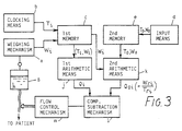
- the aiming value outputting means (corresponding to C in Figure 1) consists of a memory e and an aiming flow rate computing means k.
- the memory e stores, as an aiming flow rate defining data, a total weight Wo to be infused and an aiming time period To.
- the aiming flow rate computing means k first derives a remaining weight from the weight data W i outputted from the weighing scale and then computes, from the above derived remaining weight, a flow rate Q oi necessary for the remaining weight to be completely infused at the end of the aiming time period To.
- the data processing means comprises a first arithmetic means j for calculating the current flow rate Q i of the medicine on the basis of the data stored in the first memory c, a second arithmetic means k for calculating the subsequent remaining flow rates Q oi on the basis of the current remaining weight W ri and the current remaining period of time T ri corresponding to the aiming weight W o and the aiming period of time T o , a comparison and subtraction mechanism 1 for comparing the values obtained by the first and second arithmetic means, the resulting difference being used as input to the flow control mechanism m for adjusting the current flow rate Qi of the medicine from the container B to the remaining flow rate.
- FIG. 5 illustrates a common appearance of the present invention applied to a usual drip infusion system.
- a housing 1 which is mounted on top of the pole 2 of a drip infusion system, encloses therein the electronic part shown in Figure 3 including the weighing scale 11 with the keyboard 13 and the display 14 made to appear on the front panel of the housing 1.
- the medicine bottle g of the drip infusion system is hanged down on a hook 11a having a mechanical connection to the weighing scale 11 hidden by the housing 1. From the medicine bottle g is led the infusion tube h to a (not shown) patient through the flow rate regulation mechanism F. Midway of the infusion tube h there may be provided a drip chamber d.
- the flow rate regulation mechanism F consists of a holder 41 having a cut-in groove 41a, an eccentric cam 42 provided in the groove 41 and the pulse motor 43 for rotating the cam 42. Between the bottom of the groove 41a and the eccentric cam 42 is inserted the infusion tube h. In such a constitution of the flow rate regulation mechanism F, the degree of throttling the infusion tube h is varied depending on the rotation angle of the eccentric cam 42.
- the electric wiring to the pulse motor 43 from the driver 16 hidden by the housing 1 is not shown in Figure 5.
- the above embodiment can be modified by adding an alarming means for alarming in an emergency and/or means for stopping the control operation.
Description
- The present invention relates to an apparatus to automatically control the infusion rate or speed of a drip infusion system.
- As a method of injecting a medical solution into a living body, a drip infusion system is well known, in which a medical solution contained in a medicine bottle is gravitationally infused into an object through an infusion tube provided at one end with an infusion needle, the tube connecting between the bottle and the object with the needle thrusted into the body. Midway of the infusion tube there are provided in series a transparent drip chamber and a flow rate regulation clamp. The flow rate of the medical solution being infused is manually controlled with the clamp adjusted depending on intuition and experience in accordance with the size and frequency of droplets seen falling in the drip chamber. In spite of the fact that the speed of infusion is possibly an important factor in medical treatment, it is difficult or troublesome to obtain an optimum infusion condition by means of such a manual flow rate control made depending on intuition and experience. Further, it is inconvenient that the clamping is necessarily readjusted for a temperature variation, because the infusion speed depends on temperature through the temperature dependence of the viscosity and surface tension of the medical solution.
- The present invention aims at improving the above mentioned inconveniences and disadvantages accompanying a simple drip infusion system, and makes it an object to provide a drip infusion rate apparatus, which automatically controls the flow rate of the medical solution being infused into a living body by a drip infusion system.
- British Patent Specification GB-A-2054200 describes apparatus for this purpose in which the weight of a container holding the solution is sensed and a signal representing this actual weight is compared with a reference signal representing the ideal weight resulting from infusion at the rate necessary to dispense a desired amount over a specified period of time, any difference resulting from the comparison being used to adjust the flow-rate regulating clamp.
- European Patent Specification EP-A-0100682 similarly monitors the weight of the container from which the solution is dispensed. The loss of weight over the time from commencement of infusion provides a measure of the actual delivery rate and this is compared with a pre-set delivery rate, the result of the comparison again being used to adjust the rate of delivery of the solution.
- In accordance with the present invention there is provided a drip infusion rate control apparatus for controlling the flow rate of a medical solution into a human or animal body, the apparatus comprising a weighing mechanism for measuring the weight of a medicine container from which the solution flows to the body through an infusion tube, a flow control mechanism for increasing or decreasing the flow rate of the medicine from the container through the tube in response to an input control signal, a clocking means for measuring a period of time passing from the initiation of infusion into a human or animal body, a first memory for storing as paired data the periods of time measured by the clocking means and the weights measured by the weighing mechanism taken in as time goes, and an input means for inputting an aiming weight of a medicine to be infused and an aiming period of time required for infusion, a second memory for storing the input contents, and a data processing means for supplying a control signal to the flow control mechanism on the basis of the contents of the first memory and the second memory, characterized in that the data processing means comprises a first arithmetic means for calculating the current flow rate of the medicine on the basis of the data stored in the first memory, a second arithmetic means for calculating the subsequent remaining flow rates on the basis of the current remaining weight and the current remaining period of time corresponding to the aiming weight and the aiming period of time, a comparison and subtraction mechanism for comparing the values obtained by the first and second arithmetic means, the resulting difference being used as input to the flow control mechanism for adjusting the current flow rate of the medicine from the container to the remaining flow rate.
- Embodiments of the invention also include a function for temporarily stopping the control operation for the purpose of complying, for instance, with a condition in which a proper control operation is made impossible because of the medicine bottle and infusion tube violently rolling and swinging owing to transferring the infusion system together with a patient receiving the infusion.
- This function can be put into action by a manual switching operation.
- Thus the infusion rate control can be temporarily stopped to avoid an erroneous control operation possibly arising, for instance, when the infusion system is transferred together with a patient receiving the infusion. Further, the infusion operation can also be stopped automatically with an alarm raised when the infusion rate happens to deviate from a predetermined allowable range for some reason or other.
- The present invention is described in further detail in the following on reference to the accompanying drawing, in which:
- Figure 1 is a block diagram showing the fundamental functional constitution of an apparatus similar to that described in EP-A-0100682;
- Figure 2 shows a computerized electronic constitution for the apparatus of Figure 1;
- Figure 3 is a block diagram showing the functional constitution of an embodiment of the present invention;
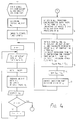
- Figure 4 is a flow chart showing the operation of the embodiment of Figure 3;
- Figure 5 shows a common appearance of the present invention applied to a drip infusion system;
- Figure 6 shows a flow rate regulation mechanism to be used in the present invention; and
- Figure 7 shows another flow rate regulation mechanism to be used in the present invention.
- Referring to Figure 1, which illustrates the fundamental constitution of the apparatus, a weight measuring means A outputs a time-dependently varying weight W(t) of a medicine bottle g, from which a medical solution is being infused into a (not shown) patient through an infusion tube h. The varying weight W(t) is inputted to a flow rate computing means B, which computes from W(t) a value reflecting an existing medical solution flow rate. On the other hand, a set of reference flow rate data which defines an aiming flow rate is outputted from an aiming value outputting means C. Any data necessary for the aiming value outputting means C to output the set of reference flow rate data are manually inputted through a basic data inputting means D. The existing flow rate reflecting value outputted from the flow rate computing means is compared, at a comparator E, with the set of reference flow rate data outputted from the aiming value outputting means C. Then the comparator C outputs a flow rate regulation signal to a flow rate regulation mechanism F interposed midway of the infusion tube g. The flow rate regulation mechanism finally controls the flow rate of the medical solution at a predetermined aiming value.
- Such a functional constitution is practiced in a computerized electronic system as shown in Fig. 2. In the figure, a
weighing scale 11 for weighing a medicine bottle g containing a medical solution consists, for example, of a load cell and an amplifier combined with an A-D converter. A series of time-dependently varying weight data W(ti) (ti: time) outputted from theweighing scale 11 is transferred to a micro-computerizedarithmetic control part 12, which includes aCPU 12a to practice an arithmetic program and to control instruments concerned, aROM 12b, and aRAM 12c. TheRAM 12c has a first, a second and a third area. The first area always stores n successive weight data W(ti) from theweighing scale 11 with the oldest datum shifted each time a newest weight datum is inputted. Each time the newest datum is taken in, the n weight data are subjected to an arithmetic operation of averaging. The thus obtained successive average values are transferred, as proper values Wj (j: integers) of the time-dependently varying weight of the medicine bottle g (Figure 2(A)), to the second area, which always accepts m values of Wj (W1, W2, ....Wm) with the oldest value W1 shifted each time a newest value Wm+1 is taken in as W1. Further, each time the second area is thus renewed, a difference
keyboard 13 manually in advance. The above weight difference dW representing an existing flow rate is compared with the weight value Wa representing an aiming flow rate. The result of comparison is outputted through aninterface 15 to adriver 16 of apulse motor 43, which is attached to an infusion flow rate regulation mechanism F (refer to Figure 1) devised so as to adjust the clamping degree of the infusion tube h. The infusion flow rate regulation mechanism F is later described in detail in conjunction with the description of an outward appearing setup of the embodiment. In the comparison of dW with Wa, if dW exceeds Wa, thedriver 16 drives thepulse motor 43 to squeeze the infusion tube; if dW is smaller than Wa, thepulse motor 43 is driven to loosen the clamping of the infusion tube; and if dW is equal to Wa, thepulse motor 43 is not driven, and the degree of clamping the tube is kept unchanged. The above described operation is carried out in accordance with a program stored in theROM 12b. - An embodiment of the present invention is described in the following with reference to Figure 3, which shows the functional constitution of the embodiment. In this embodiment, though the parts for deriving an existing flow rate and the reference flow rate data are similar to those of the apparatus of Figure 1, the aiming value outputting means (corresponding to C in Figure 1) consists of a memory e and an aiming flow rate computing means k. The memory e stores, as an aiming flow rate defining data, a total weight Wo to be infused and an aiming time period To. The aiming flow rate computing means k first derives a remaining weight from the weight data Wi outputted from the weighing scale and then computes, from the above derived remaining weight, a flow rate Qoi necessary for the remaining weight to be completely infused at the end of the aiming time period To.
- Thus in this embodiment the data processing means comprises a first arithmetic means j for calculating the current flow rate Qi of the medicine on the basis of the data stored in the first memory c, a second arithmetic means k for calculating the subsequent remaining flow rates Qoi on the basis of the current remaining weight Wri and the current remaining period of time Tri corresponding to the aiming weight Wo and the aiming period of time To, a comparison and
subtraction mechanism 1 for comparing the values obtained by the first and second arithmetic means, the resulting difference being used as input to the flow control mechanism m for adjusting the current flow rate Qi of the medicine from the container B to the remaining flow rate. - The functional constitution described is practised in a computerized electronic system similar to that of Figure 2 but using the program shown in Figure 4.
- The outward appearance of the embodiment is shown in Figure 5, which illustrates a common appearance of the present invention applied to a usual drip infusion system. A
housing 1, which is mounted on top of thepole 2 of a drip infusion system, encloses therein the electronic part shown in Figure 3 including theweighing scale 11 with thekeyboard 13 and thedisplay 14 made to appear on the front panel of thehousing 1. The medicine bottle g of the drip infusion system is hanged down on ahook 11a having a mechanical connection to the weighingscale 11 hidden by thehousing 1. From the medicine bottle g is led the infusion tube h to a (not shown) patient through the flow rate regulation mechanism F. Midway of the infusion tube h there may be provided a drip chamber d. The detail of the flow rate regulation mechanism F is described on reference to Fig. 6, which shows a cross-sectional view of the mechanism. Referring to Figure 6, the flow rate regulation mechanism F consists of aholder 41 having a cut-ingroove 41a, aneccentric cam 42 provided in thegroove 41 and thepulse motor 43 for rotating thecam 42. Between the bottom of thegroove 41a and theeccentric cam 42 is inserted the infusion tube h. In such a constitution of the flow rate regulation mechanism F, the degree of throttling the infusion tube h is varied depending on the rotation angle of theeccentric cam 42. The electric wiring to thepulse motor 43 from thedriver 16 hidden by thehousing 1 is not shown in Figure 5. - Further, the above embodiment can be modified by adding an alarming means for alarming in an emergency and/or means for stopping the control operation.
Claims (1)
- A drip infusion rate control apparatus for controlling the flow rate of a medical solution into a human or animal body, the apparatus comprising a weighing mechanism (a) for measuring the weight of a medicine container (B) from which the solution flows to the body through an infusion tube, a flow control mechanism (m) for increasing or decreasing the flow rate of the medicine from the container (B) through the tube in response to an input control signal, a clocking means (b) for measuring a period of time passing from the initiation of infusion into a human or animal body, a first memory (c) for storing as paired data the periods of time (Ti) measured by the clocking means (b) and the weights (Wi) measured by the weighing mechanism (a) taken in as time goes, and an input means (d) for inputting an aiming weight (Wo) of a medicine to be infused and an aiming period of time (To) required for infusion, a second memory (e) for storing the input contents, and a data processing means for supplying a control signal to the flow control mechanism (m) on the basis of the contents of the first memory and the second memory,
characterized in that the data processing means comprises a first arithmetic means (j) for calculating the current flow rate (Qi) of the medicine on the basis of the data stored in the first memory (c), a second arithmetic means (k) for calculating the subsequent remaining flow rates (Qoi) on the basis of the current remaining weight (Wri) and the current remaining period of time (Tri) corresponding to the aiming weight (Wo) and the aiming period of time (To), a comparison and subtraction mechanism (1) for comparing the values obtained by the first and second arithmetic means, the resulting difference being used as input to the flow control mechanism (m) for adjusting the current flow rate (Qi) of the medicine from the container (B), to the remaining flow rate (Qoi).
Applications Claiming Priority (8)
| Application Number | Priority Date | Filing Date | Title |
|---|---|---|---|
| JP46217/87 | 1987-02-27 | ||
| JP62046217A JPS63212371A (en) | 1987-02-27 | 1987-02-27 | Drug liquid injection flow rate control apparatus |
| JP62193996A JP2557402B2 (en) | 1987-08-03 | 1987-08-03 | Flow control device for chemical injection |
| JP193996/87 | 1987-08-03 | ||
| JP62215919A JP2595985B2 (en) | 1987-08-28 | 1987-08-28 | Flow control device for chemical liquid injection |
| JP215919/87 | 1987-08-28 | ||
| JP215918/87 | 1987-08-28 | ||
| JP62215918A JPS6458261A (en) | 1987-08-28 | 1987-08-28 | Flow amount control apparatus for injecting drug liquid |
Publications (2)
| Publication Number | Publication Date |
|---|---|
| EP0286221A1 EP0286221A1 (en) | 1988-10-12 |
| EP0286221B1 true EP0286221B1 (en) | 1994-09-07 |
Family
ID=27461842
Family Applications (1)
| Application Number | Title | Priority Date | Filing Date |
|---|---|---|---|
| EP88301746A Expired - Lifetime EP0286221B1 (en) | 1987-02-27 | 1988-02-29 | Drip infusion rate control apparatus |
Country Status (3)
| Country | Link |
|---|---|
| US (1) | US4889528A (en) |
| EP (1) | EP0286221B1 (en) |
| DE (1) | DE3851358D1 (en) |
Families Citing this family (58)
| Publication number | Priority date | Publication date | Assignee | Title |
|---|---|---|---|---|
| US5116312A (en) * | 1989-11-03 | 1992-05-26 | The Uab Research Foundation | Method and apparatus for automatic autotransfusion |
| FR2680975B1 (en) † | 1991-09-10 | 1998-12-31 | Hospal Ind | ARTIFICIAL KIDNEY WITH MEANS FOR DETERMINING A SUBSTANCE IN BLOOD. |
| US5219330A (en) * | 1991-11-26 | 1993-06-15 | Imed Corporation | Method and apparatus for preprogrammed infusion of iv medicaments |
| US5609575A (en) * | 1994-04-11 | 1997-03-11 | Graseby Medical Limited | Infusion pump and method with dose-rate calculation |
| US5637093A (en) * | 1995-03-06 | 1997-06-10 | Sabratek Corporation | Infusion pump with selective backlight |
| US5904668A (en) * | 1995-03-06 | 1999-05-18 | Sabratek Corporation | Cassette for an infusion pump |
| US5795327A (en) * | 1995-03-06 | 1998-08-18 | Sabratek Corporation | Infusion pump with historical data recording |
| US5628619A (en) * | 1995-03-06 | 1997-05-13 | Sabratek Corporation | Infusion pump having power-saving modes |
| US5620312A (en) * | 1995-03-06 | 1997-04-15 | Sabratek Corporation | Infusion pump with dual-latching mechanism |
| EP0956080B1 (en) * | 1995-11-01 | 2003-12-10 | Ethicon, Inc. | System for fluid retention management |
| US7207966B2 (en) | 1995-11-01 | 2007-04-24 | Ethicon, Inc. | System for fluid retention management |
| US6238366B1 (en) | 1996-10-31 | 2001-05-29 | Ethicon, Inc. | System for fluid retention management |
| US6468242B1 (en) | 1998-03-06 | 2002-10-22 | Baxter International Inc. | Medical apparatus with patient data recording |
| WO2003026727A1 (en) * | 2001-09-28 | 2003-04-03 | Lifevent Limited | sETHOD AND APPARATUS FOR DELIVERY OF MEDICATION |
| US20190357827A1 (en) | 2003-08-01 | 2019-11-28 | Dexcom, Inc. | Analyte sensor |
| US8886273B2 (en) | 2003-08-01 | 2014-11-11 | Dexcom, Inc. | Analyte sensor |
| US8626257B2 (en) | 2003-08-01 | 2014-01-07 | Dexcom, Inc. | Analyte sensor |
| US7591801B2 (en) | 2004-02-26 | 2009-09-22 | Dexcom, Inc. | Integrated delivery device for continuous glucose sensor |
| US7920906B2 (en) | 2005-03-10 | 2011-04-05 | Dexcom, Inc. | System and methods for processing analyte sensor data for sensor calibration |
| US9247900B2 (en) | 2004-07-13 | 2016-02-02 | Dexcom, Inc. | Analyte sensor |
| US8425416B2 (en) | 2006-10-04 | 2013-04-23 | Dexcom, Inc. | Analyte sensor |
| US8423114B2 (en) | 2006-10-04 | 2013-04-16 | Dexcom, Inc. | Dual electrode system for a continuous analyte sensor |
| US8425417B2 (en) | 2003-12-05 | 2013-04-23 | Dexcom, Inc. | Integrated device for continuous in vivo analyte detection and simultaneous control of an infusion device |
| US8774886B2 (en) | 2006-10-04 | 2014-07-08 | Dexcom, Inc. | Analyte sensor |
| US8364231B2 (en) | 2006-10-04 | 2013-01-29 | Dexcom, Inc. | Analyte sensor |
| US11633133B2 (en) | 2003-12-05 | 2023-04-25 | Dexcom, Inc. | Dual electrode system for a continuous analyte sensor |
| US8364230B2 (en) | 2006-10-04 | 2013-01-29 | Dexcom, Inc. | Analyte sensor |
| US8287453B2 (en) | 2003-12-05 | 2012-10-16 | Dexcom, Inc. | Analyte sensor |
| US8808228B2 (en) | 2004-02-26 | 2014-08-19 | Dexcom, Inc. | Integrated medicament delivery device for use with continuous analyte sensor |
| US7640048B2 (en) | 2004-07-13 | 2009-12-29 | Dexcom, Inc. | Analyte sensor |
| US20060020192A1 (en) | 2004-07-13 | 2006-01-26 | Dexcom, Inc. | Transcutaneous analyte sensor |
| US7783333B2 (en) | 2004-07-13 | 2010-08-24 | Dexcom, Inc. | Transcutaneous medical device with variable stiffness |
| US20060064053A1 (en) | 2004-09-17 | 2006-03-23 | Bollish Stephen J | Multichannel coordinated infusion system |
| US20080039820A1 (en) * | 2006-08-10 | 2008-02-14 | Jeff Sommers | Medical Device With Septum |
| US8449464B2 (en) | 2006-10-04 | 2013-05-28 | Dexcom, Inc. | Analyte sensor |
| US8275438B2 (en) | 2006-10-04 | 2012-09-25 | Dexcom, Inc. | Analyte sensor |
| US8447376B2 (en) | 2006-10-04 | 2013-05-21 | Dexcom, Inc. | Analyte sensor |
| US8562528B2 (en) | 2006-10-04 | 2013-10-22 | Dexcom, Inc. | Analyte sensor |
| US8298142B2 (en) | 2006-10-04 | 2012-10-30 | Dexcom, Inc. | Analyte sensor |
| US8478377B2 (en) | 2006-10-04 | 2013-07-02 | Dexcom, Inc. | Analyte sensor |
| US8425469B2 (en) * | 2007-04-23 | 2013-04-23 | Jacobson Technologies, Llc | Systems and methods for controlled substance delivery network |
| EP2152350A4 (en) | 2007-06-08 | 2013-03-27 | Dexcom Inc | Integrated medicament delivery device for use with continuous analyte sensor |
| EP4098177A1 (en) | 2007-10-09 | 2022-12-07 | DexCom, Inc. | Integrated insulin delivery system with continuous glucose sensor |
| US8396528B2 (en) | 2008-03-25 | 2013-03-12 | Dexcom, Inc. | Analyte sensor |
| WO2010144533A1 (en) * | 2009-06-09 | 2010-12-16 | Jacobson Technologies, Llc | Controlled delivery of substances system and method |
| CN101785886B (en) * | 2010-03-09 | 2013-02-20 | 张飞 | Real-time monitoring method and real-time monitoring device for infusion |
| WO2011115474A1 (en) * | 2010-03-17 | 2011-09-22 | Dextermedical B.V. | Device and method for setting a flow rate of liquid flowing through a drip |
| WO2012142502A2 (en) | 2011-04-15 | 2012-10-18 | Dexcom Inc. | Advanced analyte sensor calibration and error detection |
| CN103463704B (en) * | 2013-09-24 | 2015-05-20 | 巢雨 | Infusion automatic monitoring device capable of being preset and reliably stopping flow |
| CN103520799A (en) * | 2013-10-14 | 2014-01-22 | 刘炳章 | Automatic infusion monitor |
| CN103623481A (en) * | 2013-11-15 | 2014-03-12 | 青岛海尔软件有限公司 | Medical infusion alarm device |
| US9140596B2 (en) * | 2014-02-18 | 2015-09-22 | Chimei Medical Center | Method and device for detecting abnormal state of medical container |
| EP3218029A4 (en) * | 2014-11-12 | 2018-08-08 | The General Hospital Corporation | Flow rate measurement and control of infusion devices |
| CN107441589A (en) * | 2017-07-26 | 2017-12-08 | 北京小米移动软件有限公司 | Infusion monitoring method, apparatus, equipment and storage medium |
| US11382540B2 (en) | 2017-10-24 | 2022-07-12 | Dexcom, Inc. | Pre-connected analyte sensors |
| US11331022B2 (en) | 2017-10-24 | 2022-05-17 | Dexcom, Inc. | Pre-connected analyte sensors |
| CN111588943A (en) * | 2020-05-22 | 2020-08-28 | 首都医科大学附属北京天坛医院 | Automatic infusion control method, device and system |
| US11911594B2 (en) * | 2020-10-30 | 2024-02-27 | Carefusion 303, Inc. | Systems and apparatus for drip rate measurement for medical fluid administration |
Family Cites Families (7)
| Publication number | Priority date | Publication date | Assignee | Title |
|---|---|---|---|---|
| FR1468210A (en) * | 1965-02-16 | 1967-04-19 | Shell Int Research | Flow adjustment for adding small amounts of material to a fluid stream |
| US4273122A (en) * | 1976-11-12 | 1981-06-16 | Whitney Douglass G | Self contained powered injection system |
| JPS5613950A (en) * | 1979-07-12 | 1981-02-10 | Auto Syringe Inc | Method and device for controlling flow rate for transport liquid in vein |
| US4600401A (en) * | 1981-04-15 | 1986-07-15 | Baxter Travenol Laboratories | Fluid flow control system |
| US4457750A (en) * | 1981-11-02 | 1984-07-03 | Luther Medical Products, Inc. | Microprocessor controlled intravenous feed system |
| US4467844A (en) * | 1982-06-24 | 1984-08-28 | Baxter Travenol Laboratories, Inc. | Flow monitoring method and apparatus |
| CA1201999A (en) * | 1982-08-03 | 1986-03-18 | Peter G. Wheeldon | Fluid flow control process and apparatus |
-
1988
- 1988-02-29 US US07/162,059 patent/US4889528A/en not_active Expired - Fee Related
- 1988-02-29 EP EP88301746A patent/EP0286221B1/en not_active Expired - Lifetime
- 1988-02-29 DE DE3851358T patent/DE3851358D1/en not_active Expired - Lifetime
Also Published As
| Publication number | Publication date |
|---|---|
| US4889528A (en) | 1989-12-26 |
| DE3851358D1 (en) | 1994-10-13 |
| EP0286221A1 (en) | 1988-10-12 |
Similar Documents
| Publication | Publication Date | Title |
|---|---|---|
| EP0286221B1 (en) | Drip infusion rate control apparatus | |
| US4589372A (en) | Dispensing system having weight dependent control means | |
| US4670007A (en) | Fluid flow control process and apparatus | |
| EP0387724B1 (en) | Apparatus and method for detecting abnormalities in intravascular infusion | |
| US4392849A (en) | Infusion pump controller | |
| US5181910A (en) | Method and apparatus for a fluid infusion system with linearized flow rate change | |
| JP5762500B2 (en) | System for monitoring and adjusting blood glucose level and method for operating the same | |
| US5045069A (en) | Portable infusion monitor | |
| US4743228A (en) | Fluid flow monitoring method and system | |
| US4741732A (en) | Open-loop control of drug infusion | |
| US4412917A (en) | Weight controlled and hydrostatic pressure adjustable peritoneal dialysis apparatus | |
| EP3495007A1 (en) | Infusion flow-rate regulating device | |
| US20050177137A1 (en) | Administering device with temperature sensor | |
| EP0164904B1 (en) | Method of determining an infusion rate profile and infusion device | |
| CA2469376A1 (en) | Co2 monitored drug infusion system | |
| KR20110078483A (en) | Portable device for infusion therapy | |
| JPS61500589A (en) | drip device | |
| US4338932A (en) | Method and apparatus for fluid flow control | |
| JP2583140B2 (en) | Infusion monitoring device | |
| JP3198289B2 (en) | Injected chemical liquid control device | |
| JP2557402B2 (en) | Flow control device for chemical injection | |
| KR100872089B1 (en) | Assist Device for Injecting Infusion Solution | |
| JP2000507129A (en) | Intravenous injection control device | |
| JPS6114525A (en) | Device and method for sampling desired weight of substance | |
| KR101059836B1 (en) | Flow Measurement Method Using Vertical Surface Tension and Liquid Dose Control System |
Legal Events
| Date | Code | Title | Description |
|---|---|---|---|
| PUAI | Public reference made under article 153(3) epc to a published international application that has entered the european phase |
Free format text: ORIGINAL CODE: 0009012 |
|
| AK | Designated contracting states |
Kind code of ref document: A1 Designated state(s): CH DE GB IT LI |
|
| 17P | Request for examination filed |
Effective date: 19890407 |
|
| 17Q | First examination report despatched |
Effective date: 19901011 |
|
| GRAA | (expected) grant |
Free format text: ORIGINAL CODE: 0009210 |
|
| AK | Designated contracting states |
Kind code of ref document: B1 Designated state(s): CH DE GB IT LI |
|
| PG25 | Lapsed in a contracting state [announced via postgrant information from national office to epo] |
Ref country code: IT Free format text: LAPSE BECAUSE OF FAILURE TO SUBMIT A TRANSLATION OF THE DESCRIPTION OR TO PAY THE FEE WITHIN THE PRE;WARNING: LAPSES OF ITALIAN PATENTS WITH EFFECTIVE DATE BEFORE 2007 MAY HAVE OCCURRED AT ANY TIME BEFORE 2007. THE CORRECT EFFECTIVE DATE MAY BE DIFFERENT FROM THE ONE RECORDED.SCRIBED TIME-LIMIT Effective date: 19940907 Ref country code: CH Effective date: 19940907 Ref country code: LI Effective date: 19940907 |
|
| REF | Corresponds to: |
Ref document number: 3851358 Country of ref document: DE Date of ref document: 19941013 |
|
| PG25 | Lapsed in a contracting state [announced via postgrant information from national office to epo] |
Ref country code: DE Effective date: 19941208 |
|
| REG | Reference to a national code |
Ref country code: CH Ref legal event code: PL |
|
| PLBE | No opposition filed within time limit |
Free format text: ORIGINAL CODE: 0009261 |
|
| STAA | Information on the status of an ep patent application or granted ep patent |
Free format text: STATUS: NO OPPOSITION FILED WITHIN TIME LIMIT |
|
| 26N | No opposition filed | ||
| REG | Reference to a national code |
Ref country code: GB Ref legal event code: 746 Effective date: 19970110 |
|
| PGFP | Annual fee paid to national office [announced via postgrant information from national office to epo] |
Ref country code: GB Payment date: 19970219 Year of fee payment: 10 |
|
| PG25 | Lapsed in a contracting state [announced via postgrant information from national office to epo] |
Ref country code: GB Free format text: LAPSE BECAUSE OF NON-PAYMENT OF DUE FEES Effective date: 19980228 |
|
| GBPC | Gb: european patent ceased through non-payment of renewal fee |
Effective date: 19980228 |