EP0288130A2 - Interior trim foam product and method of fabrication thereof - Google Patents
Interior trim foam product and method of fabrication thereof Download PDFInfo
- Publication number
- EP0288130A2 EP0288130A2 EP88300579A EP88300579A EP0288130A2 EP 0288130 A2 EP0288130 A2 EP 0288130A2 EP 88300579 A EP88300579 A EP 88300579A EP 88300579 A EP88300579 A EP 88300579A EP 0288130 A2 EP0288130 A2 EP 0288130A2
- Authority
- EP
- European Patent Office
- Prior art keywords
- insert
- shell
- flange
- foam
- raw
- Prior art date
- Legal status (The legal status is an assumption and is not a legal conclusion. Google has not performed a legal analysis and makes no representation as to the accuracy of the status listed.)
- Granted
Links
Images

Classifications
-
- B—PERFORMING OPERATIONS; TRANSPORTING
- B29—WORKING OF PLASTICS; WORKING OF SUBSTANCES IN A PLASTIC STATE IN GENERAL
- B29C—SHAPING OR JOINING OF PLASTICS; SHAPING OF MATERIAL IN A PLASTIC STATE, NOT OTHERWISE PROVIDED FOR; AFTER-TREATMENT OF THE SHAPED PRODUCTS, e.g. REPAIRING
- B29C44/00—Shaping by internal pressure generated in the material, e.g. swelling or foaming ; Producing porous or cellular expanded plastics articles
- B29C44/02—Shaping by internal pressure generated in the material, e.g. swelling or foaming ; Producing porous or cellular expanded plastics articles for articles of definite length, i.e. discrete articles
- B29C44/12—Incorporating or moulding on preformed parts, e.g. inserts or reinforcements
- B29C44/1228—Joining preformed parts by the expanding material
-
- B—PERFORMING OPERATIONS; TRANSPORTING
- B29—WORKING OF PLASTICS; WORKING OF SUBSTANCES IN A PLASTIC STATE IN GENERAL
- B29C—SHAPING OR JOINING OF PLASTICS; SHAPING OF MATERIAL IN A PLASTIC STATE, NOT OTHERWISE PROVIDED FOR; AFTER-TREATMENT OF THE SHAPED PRODUCTS, e.g. REPAIRING
- B29C44/00—Shaping by internal pressure generated in the material, e.g. swelling or foaming ; Producing porous or cellular expanded plastics articles
- B29C44/02—Shaping by internal pressure generated in the material, e.g. swelling or foaming ; Producing porous or cellular expanded plastics articles for articles of definite length, i.e. discrete articles
- B29C44/12—Incorporating or moulding on preformed parts, e.g. inserts or reinforcements
- B29C44/1257—Joining a preformed part and a lining, e.g. around the edges
-
- B—PERFORMING OPERATIONS; TRANSPORTING
- B29—WORKING OF PLASTICS; WORKING OF SUBSTANCES IN A PLASTIC STATE IN GENERAL
- B29C—SHAPING OR JOINING OF PLASTICS; SHAPING OF MATERIAL IN A PLASTIC STATE, NOT OTHERWISE PROVIDED FOR; AFTER-TREATMENT OF THE SHAPED PRODUCTS, e.g. REPAIRING
- B29C65/00—Joining or sealing of preformed parts, e.g. welding of plastics materials; Apparatus therefor
- B29C65/56—Joining or sealing of preformed parts, e.g. welding of plastics materials; Apparatus therefor using mechanical means or mechanical connections, e.g. form-fits
- B29C65/567—Joining or sealing of preformed parts, e.g. welding of plastics materials; Apparatus therefor using mechanical means or mechanical connections, e.g. form-fits using a tamping or a swaging operation, i.e. at least partially deforming the edge or the rim of a first part to be joined to clamp a second part to be joined
- B29C65/568—Joining or sealing of preformed parts, e.g. welding of plastics materials; Apparatus therefor using mechanical means or mechanical connections, e.g. form-fits using a tamping or a swaging operation, i.e. at least partially deforming the edge or the rim of a first part to be joined to clamp a second part to be joined using a swaging operation, i.e. totally deforming the edge or the rim of a first part to be joined to clamp a second part to be joined
-
- B—PERFORMING OPERATIONS; TRANSPORTING
- B29—WORKING OF PLASTICS; WORKING OF SUBSTANCES IN A PLASTIC STATE IN GENERAL
- B29C—SHAPING OR JOINING OF PLASTICS; SHAPING OF MATERIAL IN A PLASTIC STATE, NOT OTHERWISE PROVIDED FOR; AFTER-TREATMENT OF THE SHAPED PRODUCTS, e.g. REPAIRING
- B29C66/00—General aspects of processes or apparatus for joining preformed parts
- B29C66/50—General aspects of joining tubular articles; General aspects of joining long products, i.e. bars or profiled elements; General aspects of joining single elements to tubular articles, hollow articles or bars; General aspects of joining several hollow-preforms to form hollow or tubular articles
- B29C66/51—Joining tubular articles, profiled elements or bars; Joining single elements to tubular articles, hollow articles or bars; Joining several hollow-preforms to form hollow or tubular articles
- B29C66/54—Joining several hollow-preforms, e.g. half-shells, to form hollow articles, e.g. for making balls, containers; Joining several hollow-preforms, e.g. half-cylinders, to form tubular articles
- B29C66/545—Joining several hollow-preforms, e.g. half-shells, to form hollow articles, e.g. for making balls, containers; Joining several hollow-preforms, e.g. half-cylinders, to form tubular articles one hollow-preform being placed inside the other
-
- B—PERFORMING OPERATIONS; TRANSPORTING
- B29—WORKING OF PLASTICS; WORKING OF SUBSTANCES IN A PLASTIC STATE IN GENERAL
- B29C—SHAPING OR JOINING OF PLASTICS; SHAPING OF MATERIAL IN A PLASTIC STATE, NOT OTHERWISE PROVIDED FOR; AFTER-TREATMENT OF THE SHAPED PRODUCTS, e.g. REPAIRING
- B29C66/00—General aspects of processes or apparatus for joining preformed parts
- B29C66/70—General aspects of processes or apparatus for joining preformed parts characterised by the composition, physical properties or the structure of the material of the parts to be joined; Joining with non-plastics material
- B29C66/72—General aspects of processes or apparatus for joining preformed parts characterised by the composition, physical properties or the structure of the material of the parts to be joined; Joining with non-plastics material characterised by the structure of the material of the parts to be joined
- B29C66/727—General aspects of processes or apparatus for joining preformed parts characterised by the composition, physical properties or the structure of the material of the parts to be joined; Joining with non-plastics material characterised by the structure of the material of the parts to be joined being porous, e.g. foam
-
- B—PERFORMING OPERATIONS; TRANSPORTING
- B29—WORKING OF PLASTICS; WORKING OF SUBSTANCES IN A PLASTIC STATE IN GENERAL
- B29C—SHAPING OR JOINING OF PLASTICS; SHAPING OF MATERIAL IN A PLASTIC STATE, NOT OTHERWISE PROVIDED FOR; AFTER-TREATMENT OF THE SHAPED PRODUCTS, e.g. REPAIRING
- B29C66/00—General aspects of processes or apparatus for joining preformed parts
- B29C66/80—General aspects of machine operations or constructions and parts thereof
- B29C66/81—General aspects of the pressing elements, i.e. the elements applying pressure on the parts to be joined in the area to be joined, e.g. the welding jaws or clamps
- B29C66/814—General aspects of the pressing elements, i.e. the elements applying pressure on the parts to be joined in the area to be joined, e.g. the welding jaws or clamps characterised by the design of the pressing elements, e.g. of the welding jaws or clamps
- B29C66/8141—General aspects of the pressing elements, i.e. the elements applying pressure on the parts to be joined in the area to be joined, e.g. the welding jaws or clamps characterised by the design of the pressing elements, e.g. of the welding jaws or clamps characterised by the surface geometry of the part of the pressing elements, e.g. welding jaws or clamps, coming into contact with the parts to be joined
- B29C66/81427—General aspects of the pressing elements, i.e. the elements applying pressure on the parts to be joined in the area to be joined, e.g. the welding jaws or clamps characterised by the design of the pressing elements, e.g. of the welding jaws or clamps characterised by the surface geometry of the part of the pressing elements, e.g. welding jaws or clamps, coming into contact with the parts to be joined comprising a single ridge, e.g. for making a weakening line; comprising a single tooth
-
- B—PERFORMING OPERATIONS; TRANSPORTING
- B29—WORKING OF PLASTICS; WORKING OF SUBSTANCES IN A PLASTIC STATE IN GENERAL
- B29C—SHAPING OR JOINING OF PLASTICS; SHAPING OF MATERIAL IN A PLASTIC STATE, NOT OTHERWISE PROVIDED FOR; AFTER-TREATMENT OF THE SHAPED PRODUCTS, e.g. REPAIRING
- B29C66/00—General aspects of processes or apparatus for joining preformed parts
- B29C66/80—General aspects of machine operations or constructions and parts thereof
- B29C66/81—General aspects of the pressing elements, i.e. the elements applying pressure on the parts to be joined in the area to be joined, e.g. the welding jaws or clamps
- B29C66/814—General aspects of the pressing elements, i.e. the elements applying pressure on the parts to be joined in the area to be joined, e.g. the welding jaws or clamps characterised by the design of the pressing elements, e.g. of the welding jaws or clamps
- B29C66/8141—General aspects of the pressing elements, i.e. the elements applying pressure on the parts to be joined in the area to be joined, e.g. the welding jaws or clamps characterised by the design of the pressing elements, e.g. of the welding jaws or clamps characterised by the surface geometry of the part of the pressing elements, e.g. welding jaws or clamps, coming into contact with the parts to be joined
- B29C66/81431—General aspects of the pressing elements, i.e. the elements applying pressure on the parts to be joined in the area to be joined, e.g. the welding jaws or clamps characterised by the design of the pressing elements, e.g. of the welding jaws or clamps characterised by the surface geometry of the part of the pressing elements, e.g. welding jaws or clamps, coming into contact with the parts to be joined comprising a single cavity, e.g. a groove
-
- B—PERFORMING OPERATIONS; TRANSPORTING
- B29—WORKING OF PLASTICS; WORKING OF SUBSTANCES IN A PLASTIC STATE IN GENERAL
- B29C—SHAPING OR JOINING OF PLASTICS; SHAPING OF MATERIAL IN A PLASTIC STATE, NOT OTHERWISE PROVIDED FOR; AFTER-TREATMENT OF THE SHAPED PRODUCTS, e.g. REPAIRING
- B29C66/00—General aspects of processes or apparatus for joining preformed parts
- B29C66/80—General aspects of machine operations or constructions and parts thereof
- B29C66/83—General aspects of machine operations or constructions and parts thereof characterised by the movement of the joining or pressing tools
- B29C66/832—Reciprocating joining or pressing tools
- B29C66/8322—Joining or pressing tools reciprocating along one axis
-
- B—PERFORMING OPERATIONS; TRANSPORTING
- B29—WORKING OF PLASTICS; WORKING OF SUBSTANCES IN A PLASTIC STATE IN GENERAL
- B29C—SHAPING OR JOINING OF PLASTICS; SHAPING OF MATERIAL IN A PLASTIC STATE, NOT OTHERWISE PROVIDED FOR; AFTER-TREATMENT OF THE SHAPED PRODUCTS, e.g. REPAIRING
- B29C33/00—Moulds or cores; Details thereof or accessories therefor
- B29C33/30—Mounting, exchanging or centering
-
- B—PERFORMING OPERATIONS; TRANSPORTING
- B29—WORKING OF PLASTICS; WORKING OF SUBSTANCES IN A PLASTIC STATE IN GENERAL
- B29C—SHAPING OR JOINING OF PLASTICS; SHAPING OF MATERIAL IN A PLASTIC STATE, NOT OTHERWISE PROVIDED FOR; AFTER-TREATMENT OF THE SHAPED PRODUCTS, e.g. REPAIRING
- B29C44/00—Shaping by internal pressure generated in the material, e.g. swelling or foaming ; Producing porous or cellular expanded plastics articles
- B29C44/02—Shaping by internal pressure generated in the material, e.g. swelling or foaming ; Producing porous or cellular expanded plastics articles for articles of definite length, i.e. discrete articles
- B29C44/12—Incorporating or moulding on preformed parts, e.g. inserts or reinforcements
- B29C44/14—Incorporating or moulding on preformed parts, e.g. inserts or reinforcements the preformed part being a lining
-
- B—PERFORMING OPERATIONS; TRANSPORTING
- B29—WORKING OF PLASTICS; WORKING OF SUBSTANCES IN A PLASTIC STATE IN GENERAL
- B29C—SHAPING OR JOINING OF PLASTICS; SHAPING OF MATERIAL IN A PLASTIC STATE, NOT OTHERWISE PROVIDED FOR; AFTER-TREATMENT OF THE SHAPED PRODUCTS, e.g. REPAIRING
- B29C66/00—General aspects of processes or apparatus for joining preformed parts
- B29C66/70—General aspects of processes or apparatus for joining preformed parts characterised by the composition, physical properties or the structure of the material of the parts to be joined; Joining with non-plastics material
- B29C66/71—General aspects of processes or apparatus for joining preformed parts characterised by the composition, physical properties or the structure of the material of the parts to be joined; Joining with non-plastics material characterised by the composition of the plastics material of the parts to be joined
-
- B—PERFORMING OPERATIONS; TRANSPORTING
- B29—WORKING OF PLASTICS; WORKING OF SUBSTANCES IN A PLASTIC STATE IN GENERAL
- B29C—SHAPING OR JOINING OF PLASTICS; SHAPING OF MATERIAL IN A PLASTIC STATE, NOT OTHERWISE PROVIDED FOR; AFTER-TREATMENT OF THE SHAPED PRODUCTS, e.g. REPAIRING
- B29C66/00—General aspects of processes or apparatus for joining preformed parts
- B29C66/70—General aspects of processes or apparatus for joining preformed parts characterised by the composition, physical properties or the structure of the material of the parts to be joined; Joining with non-plastics material
- B29C66/73—General aspects of processes or apparatus for joining preformed parts characterised by the composition, physical properties or the structure of the material of the parts to be joined; Joining with non-plastics material characterised by the intensive physical properties of the material of the parts to be joined, by the optical properties of the material of the parts to be joined, by the extensive physical properties of the parts to be joined, by the state of the material of the parts to be joined or by the material of the parts to be joined being a thermoplastic or a thermoset
- B29C66/739—General aspects of processes or apparatus for joining preformed parts characterised by the composition, physical properties or the structure of the material of the parts to be joined; Joining with non-plastics material characterised by the intensive physical properties of the material of the parts to be joined, by the optical properties of the material of the parts to be joined, by the extensive physical properties of the parts to be joined, by the state of the material of the parts to be joined or by the material of the parts to be joined being a thermoplastic or a thermoset characterised by the material of the parts to be joined being a thermoplastic or a thermoset
- B29C66/7392—General aspects of processes or apparatus for joining preformed parts characterised by the composition, physical properties or the structure of the material of the parts to be joined; Joining with non-plastics material characterised by the intensive physical properties of the material of the parts to be joined, by the optical properties of the material of the parts to be joined, by the extensive physical properties of the parts to be joined, by the state of the material of the parts to be joined or by the material of the parts to be joined being a thermoplastic or a thermoset characterised by the material of the parts to be joined being a thermoplastic or a thermoset characterised by the material of at least one of the parts being a thermoplastic
-
- B—PERFORMING OPERATIONS; TRANSPORTING
- B29—WORKING OF PLASTICS; WORKING OF SUBSTANCES IN A PLASTIC STATE IN GENERAL
- B29C—SHAPING OR JOINING OF PLASTICS; SHAPING OF MATERIAL IN A PLASTIC STATE, NOT OTHERWISE PROVIDED FOR; AFTER-TREATMENT OF THE SHAPED PRODUCTS, e.g. REPAIRING
- B29C66/00—General aspects of processes or apparatus for joining preformed parts
- B29C66/80—General aspects of machine operations or constructions and parts thereof
- B29C66/81—General aspects of the pressing elements, i.e. the elements applying pressure on the parts to be joined in the area to be joined, e.g. the welding jaws or clamps
- B29C66/814—General aspects of the pressing elements, i.e. the elements applying pressure on the parts to be joined in the area to be joined, e.g. the welding jaws or clamps characterised by the design of the pressing elements, e.g. of the welding jaws or clamps
- B29C66/8141—General aspects of the pressing elements, i.e. the elements applying pressure on the parts to be joined in the area to be joined, e.g. the welding jaws or clamps characterised by the design of the pressing elements, e.g. of the welding jaws or clamps characterised by the surface geometry of the part of the pressing elements, e.g. welding jaws or clamps, coming into contact with the parts to be joined
- B29C66/81411—General aspects of the pressing elements, i.e. the elements applying pressure on the parts to be joined in the area to be joined, e.g. the welding jaws or clamps characterised by the design of the pressing elements, e.g. of the welding jaws or clamps characterised by the surface geometry of the part of the pressing elements, e.g. welding jaws or clamps, coming into contact with the parts to be joined characterised by its cross-section, e.g. transversal or longitudinal, being non-flat
- B29C66/81415—General aspects of the pressing elements, i.e. the elements applying pressure on the parts to be joined in the area to be joined, e.g. the welding jaws or clamps characterised by the design of the pressing elements, e.g. of the welding jaws or clamps characterised by the surface geometry of the part of the pressing elements, e.g. welding jaws or clamps, coming into contact with the parts to be joined characterised by its cross-section, e.g. transversal or longitudinal, being non-flat being bevelled
-
- B—PERFORMING OPERATIONS; TRANSPORTING
- B29—WORKING OF PLASTICS; WORKING OF SUBSTANCES IN A PLASTIC STATE IN GENERAL
- B29L—INDEXING SCHEME ASSOCIATED WITH SUBCLASS B29C, RELATING TO PARTICULAR ARTICLES
- B29L2031/00—Other particular articles
- B29L2031/30—Vehicles, e.g. ships or aircraft, or body parts thereof
Definitions
- the invention relates to a foamed interior trim products for the interior of a vehicle and its method of fabrication. More specifically, the invention is directed to a foamed article that includes a reinforcing insert configured and connected to an exterior shell component of a product to form a finished surface for connection to an interior vehicle body part.
- Vehicle parts which include an outer shell foamed in place with urethane foam.
- an insert is provided to define a point for connection of the part by suitable fastening means to a vehicle interior part.
- An example of such composite structures is set forth in U.S.-A-3,123,403.
- an automobile armrest is formed having two end portions thereon connected by screw fasteners to an interior body part.
- the point for connection of the armrest is an insert which is located on the interior of the automobile armrest.
- Such composite structures have a finished shell component connected by a backing layer of cellular foam to an insert. both the shell and insert are located in a moulding apparatus in spaced relationship to form a cavity for the foam precursors which react to form the cellular backing for the shell and the bond connection between the insert and the shel.
- the moulded part is then joined to a separate backplate by suitable fastening means that connect to the insert and/or the shell to form an article which appears finished on both the interior and exterior portions of the final article.
- Composite structures like console or glove compartment doors can be configured to have shells formed from flexible polyvinyl chloride surfaces which blend with other components of a vehicle interior having a like covering.
- the backplate covers raw edges of the moulded insert and shell components. Consequently, there are no raw edges and foam flash that can catch clothes or the like when the door is opened.
- U.S.-A-3,620,566 discloses a passenger compartment armrest with a base plate held in place by welds.
- U.S.-A-3,773,875 discloses a method for manufacturing a foamed article. These Patents do not disclose the use of an insert to cover raw edges of an intermediate composite structure.
- One object of the present invention is to eliminate the need for a separate backplate component and the need for it to be fastened by suitable fastening means such as screws to foam moulded shell and insert components of the part.
- Typical vehicle interior trim parts to which the invention is applicable the door panels, clusters, armrests, consoles and instrument panel pads of the type having a foamed in place core bonded to and backing an outer skin of flexible material such as polyvinyl chloride material which is reinforced by a mould insert part that is located during the moulding with respect to the raw edge of the outer shell to form a space therebetween into which the foam material is reacted and flowed for form a light weight cellular core.
- a mould insert part that is located during the moulding with respect to the raw edge of the outer shell to form a space therebetween into which the foam material is reacted and flowed for form a light weight cellular core.
- One improved method of manufacture interior vehicle trim parts in accordance with the invention includes the steps of: preforming a part having an outer shell in the form of a flexible skin backed by a layer of cellular foam material that serves to bond the outer shell to a mould insert member that has a planar extent to extend across the full planar extent of an area bounded by a raw peripheral edge of the shell and wherein the foam material is flowed between the raw edge of the shell and an outer peripheral surface of the insert; and providing the insert with an as-moulded post formed flange located in close proximity to the raw edge of the preformed part and extending in a generally perpendicular relationship with the surface of the insert; and thereafter placing preformed skin, foam and insert components in a female nest and supporting the preformed components with respect to a heat and pressure source to apply heat and pressure to the insert flange causing it to be post formed into overlying relationship with the raw edge of the shell to cover both the raw edge of the shell and exposed foam between the insert and the raw edge thereby to define a finished rear
- a mould insert of plastic material is formed with a heat deformable feature thereon that can be displaced to cover the raw edge and exposed foam parts of a preformed part having an outer shell of flexible polymeric material backed by a core of foamed material and wherein the feature is configured to pinch off both the raw edge and the exposed foam portion of the preformed parts thereby to form a finished back surface.
- a vehicle interior trim part for use as a vehicle interior trim and a method of fabrication of such vehicle door in which a mould is used to fabricate a door composite having an outer shell, a backing of cellular foam material and a mould insert wherein the mould insert is premoulded to have a vertical flange; and wherein the vertical flange is post formed to define a finished edge that covers raw edge of foam and shell material.
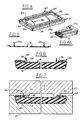
- FIG. 4 shows a representative type of glove compartment door 10.
- the door includes an outer shell or skin 12 of flexible grained polyvinyl chloride material which can be formed by a process of the type set forth in U.S. Patent No. 4,562,032 thereby to retain a highly grained appearance on the exterior shell face 14.
- An insert 16 forms the back of the door 10.
- the mould tooling apparatus in the present invention is configured as shown in Figures 1 to 3 to form a preformed part.
- a cover 18 of the mould apparatus supports the mould insert 16 in spaced relationship to a mould cavity part 20.
- the insert 16 can be preloaded as shown in dotted line at 16a in Figure 2.
- Cavity part 20 supports the outer shell 12.
- the insert 16 is a plastic part having a planar extent 24 substantially equal to that of an opening 26 in the outer shell 12 which is defined by a raw edge 28 formed thereon around the periphery of the outer shell 12.
- the insert 24 includes a peripheral edge 30 that is located by the mould cover 18 to be located in close spaced relationship to the raw edge 28 which is turned thereover by pivotal tool inserts and/or slides 32 as shown in Figures 2 and 3 to cover the edge 30.
- the insert 24 more particularly includes an integral post formed flange 34 with segments 34a on the sides and 34b on the ends of the insert 24 to be located in close relationships with the distal end of the raw edge 28.
- Each segment 34a, 34b is arranged generally perpendicularly with respect to a planar extent 35 on the insert 24.
- the cover 32 is closed and sealed with respect to the mould cavity part 20.
- the insert 24 includes an opening 36 for receiving foam precursors from a foam pour nozzle 38 which will feed the foam precursors into a cavity 40 formed between the mould supported outer shell 12 and the mould supported insert 24. The foam precursors react within the cavity and flow into a peripheral space 41 formed around the spaced insert 24 and the shell at the outer edges thereof.
- an intermediate composite structure 42 is removed from the moulding apparatus of Figure 1 which is of the configuration shown in Figure 6.
- the intermediate composite structure 42 thus includes an exterior surface defined by the outer shell 12.
- a raw edge of foam and vinyl are formed continuously around the insert 24 at a point adjacent the vertical flange 34 thereon.
- the post forming operation includes applying a heated die 50 against the flange 34 to cause it to be post formed from its vertical position. More particularly, the heat die includes a curved surface 52 thereon that will engage the distal end of the flange 34 as the heated die 50 is moved progressively toward the female nest.
- the curved surface 25 progressively deflects the flange 34 in an outward direction into an overlying relationship with the raw edge 28 until the face 54 of the flange 34 is juxtaposed against the outboard peripheral surface 56 of the outer shell 12.
- the heated die maintains heat and pressure on the post formed flange 34 to cause it to net out to the outer shell 12 and to form a continuously formed connector flange 58 that covers the raw edge 28 and the exposed foam portions 59 of the intermediate composite structure 42 a net out condition interface therebetween.
- the pour opening 36 in the insert is covered by a decorative plug 60.
- an end gate can be provided which is covered under the post formed flange 34 at the hinge mounting surface 64 by providing a notch in the edge of shell 12 and a hole 61 through insert 12 at the notch.
- the glove compartment door 10 thus includes a back which has a finished appearance without raw edges.
- the construction eliminates the need for a separate backing plate and fasteners for securing such a separating backing plate to the insert.
- the formed connector flange 58 can serve as a structural component for the connection of a hinge assembly 62. More particularly, the longitudinal reach 64 of the connector flange is arranged to support a first hinge plate 66.
- the first hinge plate 66 is connected to the connector flange by a suitable fastening means such as screws 68 that can not only be connected to the connector flange 58, but can extend therethrough to be fastened to the inboard segment of the insert 16 which underlies the formed connector flange 58.
- the second hinge plate has holes therein that will receive suitable fastening means for connecting the second hinge plate to a structural portion of the vehicle interior to locate the door 10 in an open or closed position with respect to a glove compartment opening.
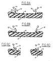
- FIGS 8A to 8D show steps of a second method embodiment.
- the flange 34 is first heated by hot air from blower 17 until it is in a reformable state.
- a series of rollers 72 are sequentially passed over the flange 34 to cause it to be post formed over the raw edge of a shell.
Abstract
Description
- The invention relates to a foamed interior trim products for the interior of a vehicle and its method of fabrication. More specifically, the invention is directed to a foamed article that includes a reinforcing insert configured and connected to an exterior shell component of a product to form a finished surface for connection to an interior vehicle body part.
- Vehicle parts are known which include an outer shell foamed in place with urethane foam. In such cases, in order to connect the part to a structural component of the the interior of a vehicle, an insert is provided to define a point for connection of the part by suitable fastening means to a vehicle interior part. An example of such composite structures is set forth in U.S.-A-3,123,403. In this arrangement, an automobile armrest is formed having two end portions thereon connected by screw fasteners to an interior body part. The point for connection of the armrest is an insert which is located on the interior of the automobile armrest.
- Such composite structures have a finished shell component connected by a backing layer of cellular foam to an insert. both the shell and insert are located in a moulding apparatus in spaced relationship to form a cavity for the foam precursors which react to form the cellular backing for the shell and the bond connection between the insert and the shel. The moulded part is then joined to a separate backplate by suitable fastening means that connect to the insert and/or the shell to form an article which appears finished on both the interior and exterior portions of the final article. Composite structures like console or glove compartment doors can be configured to have shells formed from flexible polyvinyl chloride surfaces which blend with other components of a vehicle interior having a like covering. The backplate covers raw edges of the moulded insert and shell components. Consequently, there are no raw edges and foam flash that can catch clothes or the like when the door is opened.
- U.S.-A-3,620,566 discloses a passenger compartment armrest with a base plate held in place by welds. U.S.-A-3,773,875 discloses a method for manufacturing a foamed article. These Patents do not disclose the use of an insert to cover raw edges of an intermediate composite structure.
- One object of the present invention is to eliminate the need for a separate backplate component and the need for it to be fastened by suitable fastening means such as screws to foam moulded shell and insert components of the part.
- Typical vehicle interior trim parts to which the invention is applicable, the door panels, clusters, armrests, consoles and instrument panel pads of the type having a foamed in place core bonded to and backing an outer skin of flexible material such as polyvinyl chloride material which is reinforced by a mould insert part that is located during the moulding with respect to the raw edge of the outer shell to form a space therebetween into which the foam material is reacted and flowed for form a light weight cellular core. We propose providing means on the mould insert that will serve to both cover the raw edge of the skin and to net out the insert to the outer skin so as to define a back for the part which is also bonded to the cellular core, thereby to eliminate a separate backing plate and its fasteners.
- One improved method of manufacture interior vehicle trim parts in accordance with the invention includes the steps of: preforming a part having an outer shell in the form of a flexible skin backed by a layer of cellular foam material that serves to bond the outer shell to a mould insert member that has a planar extent to extend across the full planar extent of an area bounded by a raw peripheral edge of the shell and wherein the foam material is flowed between the raw edge of the shell and an outer peripheral surface of the insert; and providing the insert with an as-moulded post formed flange located in close proximity to the raw edge of the preformed part and extending in a generally perpendicular relationship with the surface of the insert; and thereafter placing preformed skin, foam and insert components in a female nest and supporting the preformed components with respect to a heat and pressure source to apply heat and pressure to the insert flange causing it to be post formed into overlying relationship with the raw edge of the shell to cover both the raw edge of the shell and exposed foam between the insert and the raw edge thereby to define a finished rear wall surface.
- In accordance with other principles of the present invention, a mould insert of plastic material is formed with a heat deformable feature thereon that can be displaced to cover the raw edge and exposed foam parts of a preformed part having an outer shell of flexible polymeric material backed by a core of foamed material and wherein the feature is configured to pinch off both the raw edge and the exposed foam portion of the preformed parts thereby to form a finished back surface.
- Also, according to the present invention, we propose a vehicle interior trim part for use as a vehicle interior trim and a method of fabrication of such vehicle door in which a mould is used to fabricate a door composite having an outer shell, a backing of cellular foam material and a mould insert wherein the mould insert is premoulded to have a vertical flange; and wherein the vertical flange is post formed to define a finished edge that covers raw edge of foam and shell material.
- Embodiments of the invention will now be described by way of example with reference to the accompanying drawings in which:
- Figures 1 to 3 are diagrammatic views of mould tooling to form a composite structure including an outer shell and mould insert component to provide a cellular foam backing with respect to the shell;
- Figure 2a is a fragmentary view of an alternative gate location;
- Figure 4 is a perspective view of a composite plastic door structure;
- Figure 4a is as fragmentary view of a corner of the structure;
- Figure 5 is a section view of an insert component of the composite structure formed in the mould tooling of Figures 1 to 3;
- Figure 6 is a sectional view of the composite structure made by the moulding apparatus of Figures 1 to 3; and
- Figure 7 is a sectional view of a heat die formation of the insert to form a raw edge cover in the door structure of Figure 4; and
- Figures 8A - 8D are diagrammatic views of a hot air heater and roller assembly for practicing a second method of the invention.
- The article of the present invention and its method of manufacture will be described with reference to a composite plastic door such as a glove box door or a console door for use in association with the interior automotive body assembly.
- Figure 4 shows a representative type of glove compartment door 10. The door includes an outer shell or
skin 12 of flexible grained polyvinyl chloride material which can be formed by a process of the type set forth in U.S. Patent No. 4,562,032 thereby to retain a highly grained appearance on the exterior shell face 14. Aninsert 16 forms the back of thedoor 10. - The mould tooling apparatus in the present invention is configured as shown in Figures 1 to 3 to form a preformed part. A
cover 18 of the mould apparatus supports themould insert 16 in spaced relationship to amould cavity part 20. Alternatively, theinsert 16 can be preloaded as shown in dotted line at 16a in Figure 2.Cavity part 20 supports theouter shell 12. - More specifically, the
insert 16, as shown in Figures 1 and 5, is a plastic part having a planar extent 24 substantially equal to that of an opening 26 in theouter shell 12 which is defined by araw edge 28 formed thereon around the periphery of theouter shell 12. The insert 24 includes aperipheral edge 30 that is located by themould cover 18 to be located in close spaced relationship to theraw edge 28 which is turned thereover by pivotal tool inserts and/orslides 32 as shown in Figures 2 and 3 to cover theedge 30. The insert 24 more particularly includes an integral post formedflange 34 withsegments 34a on the sides and 34b on the ends of the insert 24 to be located in close relationships with the distal end of theraw edge 28. Eachsegment cover 32 is closed and sealed with respect to themould cavity part 20. The insert 24 includes anopening 36 for receiving foam precursors from afoam pour nozzle 38 which will feed the foam precursors into acavity 40 formed between the mould supportedouter shell 12 and the mould supported insert 24. The foam precursors react within the cavity and flow into a peripheral space 41 formed around the spaced insert 24 and the shell at the outer edges thereof. - Following reaction of the foam, an
intermediate composite structure 42 is removed from the moulding apparatus of Figure 1 which is of the configuration shown in Figure 6. Theintermediate composite structure 42 thus includes an exterior surface defined by theouter shell 12. On the back side of the part, a raw edge of foam and vinyl are formed continuously around the insert 24 at a point adjacent thevertical flange 34 thereon. - After completing the
intermediate composite structure 42, it is loaded into aheated die assembly 44. More particularly, the outer or exterior face 14 of theouter shell 12 is rested against theinner surface 46 of afemale nest 48. The female nest is configured to support the exterior shell face 14 so that it will remain unblemished during the post forming operation. The post forming operation includes applying a heateddie 50 against theflange 34 to cause it to be post formed from its vertical position. More particularly, the heat die includes acurved surface 52 thereon that will engage the distal end of theflange 34 as theheated die 50 is moved progressively toward the female nest. The curved surface 25 progressively deflects theflange 34 in an outward direction into an overlying relationship with theraw edge 28 until theface 54 of theflange 34 is juxtaposed against the outboardperipheral surface 56 of theouter shell 12. The heated die maintains heat and pressure on the post formedflange 34 to cause it to net out to theouter shell 12 and to form a continuously formedconnector flange 58 that covers theraw edge 28 and the exposedfoam portions 59 of the intermediate composite structure 42 a net out condition interface therebetween. The pour opening 36 in the insert is covered by adecorative plug 60. Alternatively, an end gate can be provided which is covered under the post formedflange 34 at thehinge mounting surface 64 by providing a notch in the edge ofshell 12 and ahole 61 throughinsert 12 at the notch. In such case, the need for a decorative plug is eliminated. Theglove compartment door 10 thus includes a back which has a finished appearance without raw edges. The construction eliminates the need for a separate backing plate and fasteners for securing such a separating backing plate to the insert. Nevertheless, because of the illustrated arrangement, theformed connector flange 58 can serve as a structural component for the connection of ahinge assembly 62. More particularly, thelongitudinal reach 64 of the connector flange is arranged to support afirst hinge plate 66. Thefirst hinge plate 66 is connected to the connector flange by a suitable fastening means such asscrews 68 that can not only be connected to theconnector flange 58, but can extend therethrough to be fastened to the inboard segment of theinsert 16 which underlies theformed connector flange 58. The second hinge plate has holes therein that will receive suitable fastening means for connecting the second hinge plate to a structural portion of the vehicle interior to locate thedoor 10 in an open or closed position with respect to a glove compartment opening. - Figures 8A to 8D show steps of a second method embodiment. The
flange 34 is first heated by hot air from blower 17 until it is in a reformable state. At this point a series ofrollers 72 are sequentially passed over theflange 34 to cause it to be post formed over the raw edge of a shell. - The invention herein has been described in an illustrative manner and it is understood that the terminology which has been used is intended to be in the nature of words of description rather than or limitation.
Claims (8)
Applications Claiming Priority (3)
| Application Number | Priority Date | Filing Date | Title |
|---|---|---|---|
| US3968087A | 1987-04-20 | 1987-04-20 | |
| US39680 | 1987-04-20 | ||
| US07/230,572 US4839118A (en) | 1987-04-20 | 1988-08-10 | Method of fabricating an interior trim foam product |
Publications (3)
| Publication Number | Publication Date |
|---|---|
| EP0288130A2 true EP0288130A2 (en) | 1988-10-26 |
| EP0288130A3 EP0288130A3 (en) | 1989-11-08 |
| EP0288130B1 EP0288130B1 (en) | 1993-03-17 |
Family
ID=26716358
Family Applications (1)
| Application Number | Title | Priority Date | Filing Date |
|---|---|---|---|
| EP88300579A Expired - Lifetime EP0288130B1 (en) | 1987-04-20 | 1988-01-25 | Interior trim foam product and method of fabrication thereof |
Country Status (2)
| Country | Link |
|---|---|
| US (1) | US4839118A (en) |
| EP (1) | EP0288130B1 (en) |
Cited By (6)
| Publication number | Priority date | Publication date | Assignee | Title |
|---|---|---|---|---|
| DE3914937A1 (en) * | 1989-05-06 | 1990-11-08 | Bayerische Motoren Werke Ag | Back foaming tool - with upper and lower mould, hinged in gate and sealing facilities |
| EP0410553A2 (en) * | 1989-07-26 | 1991-01-30 | LIGNOTOCK GmbH | Method for the production of lined and formed articles |
| EP0475198A2 (en) * | 1990-08-29 | 1992-03-18 | Toyoda Gosei Co., Ltd. | Compression moulding of a sheet and resin article, and product thus obtained |
| US5716563A (en) * | 1992-02-05 | 1998-02-10 | Weyerhaeuser Company | Method of forming a surfaced cellulosic composite panel |
| US5804117A (en) * | 1994-04-05 | 1998-09-08 | Toyoda Gosei Co., Ltd. | Molding method for resin articles |
| US6004498A (en) * | 1994-04-04 | 1999-12-21 | Toyoda Gosei Co. Ltd. | Method for molding resin to skin members |
Families Citing this family (9)
| Publication number | Priority date | Publication date | Assignee | Title |
|---|---|---|---|---|
| US5275779A (en) * | 1990-10-03 | 1994-01-04 | Lear Seating Corporation | Method of forming an automotive armrest with cupholder |
| US5558731A (en) * | 1994-12-19 | 1996-09-24 | Davidson Textron Inc. | Method for fabricating vinyl covered foamed parts |
| US5744077A (en) * | 1995-09-07 | 1998-04-28 | Applied Composites, Corp. | Method for fabricating a composite structure |
| US6050579A (en) * | 1998-04-21 | 2000-04-18 | Aeroquip Corporation | Automotive running board |
| US6076246A (en) * | 1998-09-18 | 2000-06-20 | Textron Automotive Company Inc. | Method for manufacturing an automotive interior trim component and the resultant construction thereof |
| US20040018789A1 (en) * | 2002-07-29 | 2004-01-29 | Marchbanks Eric L. | Molded parts with discontinuous fabric surface areas and processes for their production |
| US20040096535A1 (en) * | 2002-11-15 | 2004-05-20 | Hudecek Robert W. | Compression molding apparatus having replaceable mold inserts |
| US20090246505A1 (en) * | 2008-03-26 | 2009-10-01 | Intertec Systems, Llc | Automotive interior component with cantilevered skin portion and method of making the same |
| DE102015012152B4 (en) * | 2015-09-16 | 2018-01-25 | Faurecia Innenraum Systeme Gmbh | Method and device for producing an intermediate article for an interior trim part and method for producing an interior trim part |
Citations (6)
| Publication number | Priority date | Publication date | Assignee | Title |
|---|---|---|---|---|
| US2431238A (en) * | 1946-04-15 | 1947-11-18 | Friedman Theodore | Process of locking flat members to bodies |
| US3155751A (en) * | 1960-11-07 | 1964-11-03 | Whirlpool Co | Method of making an insulated structure |
| FR1564660A (en) * | 1967-02-15 | 1969-04-25 | ||
| US3773875A (en) * | 1968-04-01 | 1973-11-20 | Goodyear Tire & Rubber | Method of making foamed articles having a reinforcing member |
| FR2217961A5 (en) * | 1973-02-14 | 1974-09-06 | Bavant Jean | |
| US4525408A (en) * | 1982-09-09 | 1985-06-25 | Integral Profilsystem Ab | Insulation of aluminum profiles in a fixture |
Family Cites Families (2)
| Publication number | Priority date | Publication date | Assignee | Title |
|---|---|---|---|---|
| US3308225A (en) * | 1963-10-16 | 1967-03-07 | Robert M Wells | Method of forming mechanically interlocked heat seal engagement between a bottom plate and a plastic container in a coffee percolator, or other receptacle |
| US3303255A (en) * | 1965-01-11 | 1967-02-07 | Mobil Oil | Process for bonding thermoplastic materials |
-
1988
- 1988-01-25 EP EP88300579A patent/EP0288130B1/en not_active Expired - Lifetime
- 1988-08-10 US US07/230,572 patent/US4839118A/en not_active Expired - Fee Related
Patent Citations (6)
| Publication number | Priority date | Publication date | Assignee | Title |
|---|---|---|---|---|
| US2431238A (en) * | 1946-04-15 | 1947-11-18 | Friedman Theodore | Process of locking flat members to bodies |
| US3155751A (en) * | 1960-11-07 | 1964-11-03 | Whirlpool Co | Method of making an insulated structure |
| FR1564660A (en) * | 1967-02-15 | 1969-04-25 | ||
| US3773875A (en) * | 1968-04-01 | 1973-11-20 | Goodyear Tire & Rubber | Method of making foamed articles having a reinforcing member |
| FR2217961A5 (en) * | 1973-02-14 | 1974-09-06 | Bavant Jean | |
| US4525408A (en) * | 1982-09-09 | 1985-06-25 | Integral Profilsystem Ab | Insulation of aluminum profiles in a fixture |
Non-Patent Citations (1)
| Title |
|---|
| PATENT ABSTRACTS OF JAPAN, vol. 6, no. 232 (M-172)[1110], 18th November 1982; & JP-A-57 133 035 (IG GIJUTSU KENKYUSHO K.K.) 17-08-1982 * |
Cited By (8)
| Publication number | Priority date | Publication date | Assignee | Title |
|---|---|---|---|---|
| DE3914937A1 (en) * | 1989-05-06 | 1990-11-08 | Bayerische Motoren Werke Ag | Back foaming tool - with upper and lower mould, hinged in gate and sealing facilities |
| EP0410553A2 (en) * | 1989-07-26 | 1991-01-30 | LIGNOTOCK GmbH | Method for the production of lined and formed articles |
| EP0410553A3 (en) * | 1989-07-26 | 1992-04-08 | Lignotock Gmbh | Method for the production of lined and formed articles |
| EP0475198A2 (en) * | 1990-08-29 | 1992-03-18 | Toyoda Gosei Co., Ltd. | Compression moulding of a sheet and resin article, and product thus obtained |
| EP0475198A3 (en) * | 1990-08-29 | 1992-07-15 | Toyoda Gosei Co., Ltd. | Compression moulding of a sheet and resin article, and product thus obtained |
| US5716563A (en) * | 1992-02-05 | 1998-02-10 | Weyerhaeuser Company | Method of forming a surfaced cellulosic composite panel |
| US6004498A (en) * | 1994-04-04 | 1999-12-21 | Toyoda Gosei Co. Ltd. | Method for molding resin to skin members |
| US5804117A (en) * | 1994-04-05 | 1998-09-08 | Toyoda Gosei Co., Ltd. | Molding method for resin articles |
Also Published As
| Publication number | Publication date |
|---|---|
| US4839118A (en) | 1989-06-13 |
| EP0288130B1 (en) | 1993-03-17 |
| EP0288130A3 (en) | 1989-11-08 |
Similar Documents
| Publication | Publication Date | Title |
|---|---|---|
| US4892770A (en) | Interior trim foam product and method of fabrication thereof | |
| EP0288130A2 (en) | Interior trim foam product and method of fabrication thereof | |
| US5571597A (en) | Molded trim panel with integrally formed simulated leather appliques and a method for molding same | |
| JP2901051B2 (en) | Molding method of laminated molded body | |
| US5824251A (en) | Method for forming plastic molded panels with inserts | |
| US5622402A (en) | Panel with integral energy absorber and air duct | |
| US6248200B1 (en) | Method of making a trim panel assembly including integral arm rest portion | |
| US6422640B2 (en) | Door trim panel assembly and method of making | |
| EP0261760B1 (en) | Composite moulded article and method of making same | |
| JP3050366B2 (en) | Molding method and molding apparatus for laminated molded article | |
| US6120100A (en) | Composite blow molded article and method of making same | |
| US6063460A (en) | Molded polyolefin and polyphenyloxide products and method for production | |
| KR900015987A (en) | Cover for safety air cushion device and manufacturing method thereof | |
| US5252164A (en) | Method for making a supplemental impact restraint door and instrument panel system from single, unitary cover | |
| EP0343245A1 (en) | Method of manufacturing decorative sheet-carrying laminated molding | |
| US5558731A (en) | Method for fabricating vinyl covered foamed parts | |
| CA1300205C (en) | Interior trim foam product and method of fabrication thereof | |
| US6726872B1 (en) | Method for forming plastic molded panels having an undercut edge | |
| JP7374773B2 (en) | Decorative component manufacturing method | |
| US20040231784A1 (en) | Method for forming plastic molded panels with inserts | |
| JP3062011B2 (en) | Manufacturing method of foam molded article and mold used for it | |
| JP2525970B2 (en) | Car door trim | |
| JPH0641859Y2 (en) | Car door trim | |
| JPH0667577B2 (en) | Manufacturing method of automobile interior parts | |
| JPS61235111A (en) | Manufacture of lamination forming body |
Legal Events
| Date | Code | Title | Description |
|---|---|---|---|
| PUAI | Public reference made under article 153(3) epc to a published international application that has entered the european phase |
Free format text: ORIGINAL CODE: 0009012 |
|
| AK | Designated contracting states |
Kind code of ref document: A2 Designated state(s): DE FR GB IT SE |
|
| PUAL | Search report despatched |
Free format text: ORIGINAL CODE: 0009013 |
|
| AK | Designated contracting states |
Kind code of ref document: A3 Designated state(s): DE FR GB IT SE |
|
| 17P | Request for examination filed |
Effective date: 19900424 |
|
| 17Q | First examination report despatched |
Effective date: 19910725 |
|
| GRAA | (expected) grant |
Free format text: ORIGINAL CODE: 0009210 |
|
| AK | Designated contracting states |
Kind code of ref document: B1 Designated state(s): DE FR GB IT SE |
|
| PG25 | Lapsed in a contracting state [announced via postgrant information from national office to epo] |
Ref country code: SE Effective date: 19930317 |
|
| ITF | It: translation for a ep patent filed |
Owner name: JACOBACCI CASETTA & PERANI S.P.A. |
|
| REF | Corresponds to: |
Ref document number: 3879252 Country of ref document: DE Date of ref document: 19930422 |
|
| ET | Fr: translation filed | ||
| PLBE | No opposition filed within time limit |
Free format text: ORIGINAL CODE: 0009261 |
|
| STAA | Information on the status of an ep patent application or granted ep patent |
Free format text: STATUS: NO OPPOSITION FILED WITHIN TIME LIMIT |
|
| 26N | No opposition filed | ||
| PGFP | Annual fee paid to national office [announced via postgrant information from national office to epo] |
Ref country code: FR Payment date: 19941214 Year of fee payment: 8 |
|
| PGFP | Annual fee paid to national office [announced via postgrant information from national office to epo] |
Ref country code: DE Payment date: 19941227 Year of fee payment: 8 |
|
| PGFP | Annual fee paid to national office [announced via postgrant information from national office to epo] |
Ref country code: GB Payment date: 19941228 Year of fee payment: 8 |
|
| PG25 | Lapsed in a contracting state [announced via postgrant information from national office to epo] |
Ref country code: GB Effective date: 19960125 |
|
| GBPC | Gb: european patent ceased through non-payment of renewal fee |
Effective date: 19960125 |
|
| PG25 | Lapsed in a contracting state [announced via postgrant information from national office to epo] |
Ref country code: FR Effective date: 19960930 |
|
| PG25 | Lapsed in a contracting state [announced via postgrant information from national office to epo] |
Ref country code: DE Effective date: 19961001 |
|
| REG | Reference to a national code |
Ref country code: FR Ref legal event code: ST |
|
| PG25 | Lapsed in a contracting state [announced via postgrant information from national office to epo] |
Ref country code: IT Free format text: LAPSE BECAUSE OF NON-PAYMENT OF DUE FEES Effective date: 20050125 |