EP0288215B1 - Determination of electrical capacitance and resistance - Google Patents
Determination of electrical capacitance and resistance Download PDFInfo
- Publication number
- EP0288215B1 EP0288215B1 EP88303383A EP88303383A EP0288215B1 EP 0288215 B1 EP0288215 B1 EP 0288215B1 EP 88303383 A EP88303383 A EP 88303383A EP 88303383 A EP88303383 A EP 88303383A EP 0288215 B1 EP0288215 B1 EP 0288215B1
- Authority
- EP
- European Patent Office
- Prior art keywords
- voltage
- electrical component
- polarity
- potential
- sensing
- Prior art date
- Legal status (The legal status is an assumption and is not a legal conclusion. Google has not performed a legal analysis and makes no representation as to the accuracy of the status listed.)
- Expired - Lifetime
Links
Images
Classifications
-
- G—PHYSICS
- G01—MEASURING; TESTING
- G01R—MEASURING ELECTRIC VARIABLES; MEASURING MAGNETIC VARIABLES
- G01R27/00—Arrangements for measuring resistance, reactance, impedance, or electric characteristics derived therefrom
- G01R27/02—Measuring real or complex resistance, reactance, impedance, or other two-pole characteristics derived therefrom, e.g. time constant
- G01R27/26—Measuring inductance or capacitance; Measuring quality factor, e.g. by using the resonance method; Measuring loss factor; Measuring dielectric constants ; Measuring impedance or related variables
- G01R27/2605—Measuring capacitance
-
- G—PHYSICS
- G01—MEASURING; TESTING
- G01F—MEASURING VOLUME, VOLUME FLOW, MASS FLOW OR LIQUID LEVEL; METERING BY VOLUME
- G01F23/00—Indicating or measuring liquid level or level of fluent solid material, e.g. indicating in terms of volume or indicating by means of an alarm
- G01F23/22—Indicating or measuring liquid level or level of fluent solid material, e.g. indicating in terms of volume or indicating by means of an alarm by measuring physical variables, other than linear dimensions, pressure or weight, dependent on the level to be measured, e.g. by difference of heat transfer of steam or water
- G01F23/24—Indicating or measuring liquid level or level of fluent solid material, e.g. indicating in terms of volume or indicating by means of an alarm by measuring physical variables, other than linear dimensions, pressure or weight, dependent on the level to be measured, e.g. by difference of heat transfer of steam or water by measuring variations of resistance of resistors due to contact with conductor fluid
-
- G—PHYSICS
- G01—MEASURING; TESTING
- G01F—MEASURING VOLUME, VOLUME FLOW, MASS FLOW OR LIQUID LEVEL; METERING BY VOLUME
- G01F23/00—Indicating or measuring liquid level or level of fluent solid material, e.g. indicating in terms of volume or indicating by means of an alarm
- G01F23/22—Indicating or measuring liquid level or level of fluent solid material, e.g. indicating in terms of volume or indicating by means of an alarm by measuring physical variables, other than linear dimensions, pressure or weight, dependent on the level to be measured, e.g. by difference of heat transfer of steam or water
- G01F23/26—Indicating or measuring liquid level or level of fluent solid material, e.g. indicating in terms of volume or indicating by means of an alarm by measuring physical variables, other than linear dimensions, pressure or weight, dependent on the level to be measured, e.g. by difference of heat transfer of steam or water by measuring variations of capacity or inductance of capacitors or inductors arising from the presence of liquid or fluent solid material in the electric or electromagnetic fields
- G01F23/263—Indicating or measuring liquid level or level of fluent solid material, e.g. indicating in terms of volume or indicating by means of an alarm by measuring physical variables, other than linear dimensions, pressure or weight, dependent on the level to be measured, e.g. by difference of heat transfer of steam or water by measuring variations of capacity or inductance of capacitors or inductors arising from the presence of liquid or fluent solid material in the electric or electromagnetic fields by measuring variations in capacitance of capacitors
- G01F23/266—Indicating or measuring liquid level or level of fluent solid material, e.g. indicating in terms of volume or indicating by means of an alarm by measuring physical variables, other than linear dimensions, pressure or weight, dependent on the level to be measured, e.g. by difference of heat transfer of steam or water by measuring variations of capacity or inductance of capacitors or inductors arising from the presence of liquid or fluent solid material in the electric or electromagnetic fields by measuring variations in capacitance of capacitors measuring circuits therefor
-
- G—PHYSICS
- G01—MEASURING; TESTING
- G01F—MEASURING VOLUME, VOLUME FLOW, MASS FLOW OR LIQUID LEVEL; METERING BY VOLUME
- G01F25/00—Testing or calibration of apparatus for measuring volume, volume flow or liquid level or for metering by volume
- G01F25/20—Testing or calibration of apparatus for measuring volume, volume flow or liquid level or for metering by volume of apparatus for measuring liquid level
Definitions
- the invention relates to apparatus for determining capacitance and resistance characteristics of an electrical component, comprising voltage applying means for subjecting the electrical component to a time varying voltage having a linear ramp voltage which passes from a first polarity through zero to a second polarity and for subjecting the electrical component to a fixed voltage level, sensing means operative in response to the zero crossing of the ramp voltage to sense the electrical potential across the electrical component and for sensing the potential across the electrical component when the voltage is at the fixed voltage level, and means for determining the capacitance of the electrical component from the potential sensed in response to the zero crossing and for determining the resistance of the electrical component from the potential sensed at the fixed voltage level.
- the invention also relates to a method of determining capacitive and resistive characteristics of an electrical component, comprising the steps of subjecting the component to a time varying voltage having a linear ramp voltage which passes from a first polarity through zero to a second polarity, subjecting the electrical component to a fixed voltage level, sensing the potential across the electrical component in response to the zero crossing of the ramp voltage, sensing the potential across the electrical component when the voltage is at the fixed voltage level, determining the capacitance of the electrical component from the potential sensed in response to the zero crossing, and determining the resistance of the electrical component from the potential sensed at the fixed voltage level.
- a form of such apparatus and method is known from US-A-4 080 562 and from US-A-4 147 050.
- an oscillator produces a triangular electrical waveform which is applied across the electrical component via a switch.
- a sample and hold arrangement samples the voltage developed across the electrical component at instants corresponding to the zero crossing points of the triangular waveform.
- the capacitance of the component differentiates the triangular waveform to produce a square wave displaced by 90° from the triangular waveform.
- the amplitude of the voltage across the capacitance at each sampling instant is a measure of the capacitance. Hence the capacitance value can be determined.
- a switch In order to measure the resistive value, a switch is used to apply a DC voltage from a separate source to the component so as to produce a resistive current dependent on the applied DC voltage. Another switch causes the resistive current to flow through another, much smaller, resistance so that the potential drop across the latter is a measure of the current and substantially proportional to the resistance of the component.
- Such known apparatus and method thus requires two separate sources of voltage: a triangular waveform for use in capacitance measurement and a separate DC voltage for resistance measurement. Switching means therefore has to be provided for switching between the two voltage sources. Accuracy depends on the magnitudes of the applied voltages, and there are thus two sources whose magnitudes have to be controlled in order to achieve accuracy. The invention aims to overcome these problems.
- the apparatus is characterised in that the voltage applying means comprises voltage signal generating means for subjecting the electrical component to a voltage signal having an initial voltage of the said first polarity which ramps to a voltage of the said second polarity and remains at a constant voltage of the second polarity for at least a predetermined time period to constitute the said fixed voltage level.
- the method is characterised in that the steps of subjecting the component to the time varying voltage and to the fixed voltage level comprise the step of subjecting the electrical component to a voltage signal having an initial voltage of the said first polarity which ramps to a voltage of the said second polarity and remains at a constant voltage of the second polarity for at least a predetermined time period to constitute the said fixed voltage level.
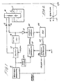
- a waveform generator 10 is connected to a switch 12 which, in turn, provides a switched output to either a sensor unit 14 or a calibration standard 16.
- the sensor unit 14 is connected in circuit through a connection interface C1/C2, and if desired, can be located in a remote position from the schematic circuit of Fig. 1.
- the sensor unit 14 is a capacitive probe mounted in a tank T containing a selected quantity of a liquid L, such as fuel.
- the sensor unit 14 and the calibration standard 16 are connected to a preamplifier 18 which provides an amplified output to a sample and hold circuit 20 which functions, as described more fully below, to sense representative voltage potentials from the sensor unit 14 or the calibration standard 16 in response to an appropriate command.
- the analog output of the sample and hold circuit 20 is provided to an analog-to-digital converter 22 which converts the analog value provided by the sample and hold circuit 20 to a corresponding multi-bit binary value.
- a system controller 26 accepts the digital values provided via a bus 28 from the analog-to-digital converter 22 and uses those values to compute capacitance and resistance values and provide an appropriate output signal to an output port OUT.
- the system controller 26 also provides control signals to a logic controller 30 which periodically provides a SAMPLE command to the sample and hold circuit 20 to sense and retain the analog voltage values provided through the preamplifier 18 by either the sensor unit 14 or the calibration standard 16.
- the system controller 26 also provides appropriate ENABLE/INHIBIT signals to the waveform generator 10 to initiate the capacitance and resistance determination cycle as well as a CAL/SEN signal to the switch 12 to select either the sensor unit 14 for evaluation or the calibration standard 16 to initiate an auto-calibration cycle.
- a zero cross-over detector 32 is connected to the output of the waveform generator 10 and provides a signal to the logic controller 30 indicating the moment when the output of the waveform generator 10 passes from a positive value through zero to a negative value and, conversely, passes from a negative value through zero to a positive value.
- the waveform generator 10 provides a voltage output having the profile shown in Fig. 2, that is, an initial value of +V that decreases in a linear manner through zero to a -V value and which then remains fixed at -V for a selected period before rising in a linear manner from -V through zero and returning to the +V potential.
- the output voltage profile shown in Fig. 2 is used to interrogate either the sensor unit 14 or the calibration standard 16 and to determine the respective capacitance and resistance values, as described below.
- the switch 12 functions as the equivalent of a single-pole, double-throw switch in response to the CAL/SEN signal provided from the system controller 26.
- the switch 12 switches the calibration standard 16 into the circuit to effect auto-calibration and, when the SEN signal is provided, the switch 12 switches the sensor unit 14 into the circuit to determine the capacitance and resistance values of the sensor unit 14.
- the preamplifier 18 preferably has a high input impedance and a gain appropriate for the waveform repetition rate.
- the zero cross-over detector 32 functions to detect the cross-over of the linearly declining and rising portions of the voltage profile of Fig. 2 and to provide an appropriate output to the logic controller 30. While a number of devices can perform the zero cross-over detect function, an operational amplifier configured as a differential amplifier driving a bi-stable device can provide the desired output signal to the logic controller 30.
- the system controller 26 is preferably a stored-program controlled micro-processor including a ROM containing an instruction set for implementing the functions described below, a RAM for storing values presented by the analog-to-digital converter 22, an accumulator, one or more general purpose storage registers, and input/output interfaces.
- the circuit of Fig. 1 operates through an interrogation cycle to determine the capacitance and resistance values associated with the calibration standard 16 or the sensor unit 14.
- the sensor unit 14 has been selected by the system controller 26 and the appropriate SEN signal presented to the switch 12, the sensor unit 14 is placed in circuit with the waveform generator 10 and the preamplifier 18 while the calibration standard 16 is effectively disconnected.
- the waveform generator 10 presents a time varying interrogation voltage through the switch 12 to the sensor unit 14.
- the interrogation voltage follows the profile shown in Fig. 2, starting at a +V value and declining in a linear manner to the -V value.
- the capacitance of the sensor unit 14 is charged with the potential rising in a manner inverse to the capacitance value.
- the zero cross-over detector 32 provides an appropriate signal to the logic controller 30 which commands the sample and hold circuit 20 to sample the output of the preamplifier 18, which output is representative of the capacitance-determined voltage potential of the sensor unit 14.
- the sampled value is converted to a digital value of selected bit width (e.g., 16 bits) with the digital value presented to the system controller 26 via the bus 28.
- the system controller 26 then computes the capacitance value for the sensor unit 14 and stores the computed value and/or provides the computed value as an output signal OUT.
- the capacitance determination can be accomplished by algebraic computation or by table look-up where the sensed voltage level is compared with empirically determined voltages and corresponding capacitance values.
- the system controller 26 presents an appropriate control signal to the logic controller 30 so as again to cause the sample and hold circuit 20 to sample the output of the preamplifier 18.
- This second sample and hold command occurs at a predetermined time period after the detection of the zero crossing when the interrogation voltage is constant at the value -V prior to rising linearly from -V to +V.
- the predetermined time period is a function of the repetition rate of the waveform generator 10.
- the voltage potential sensed by the preamplifier 18 is solely a function of the resistance of the sensor unit 14 and is independent of any capacitance effect.
- the output of the sample and hold circuit 20 is provided to the analog-to-digital converter 22 which, in a manner analogous to that described above, provides a multi-bit digital value to the system controller 26 to effect the resistance determination.
- an auto-calibration function is performed using the calibration standard 16. Measurement errors and other inaccuracies can arise from a number of sources including the time-varying voltages provided by the waveform generator 10, hysteresis in the zero cross-over detector 32, impedances in the switch 12, and various other offsets and errors.
- the system controller 26 provides an appropriate CAL selection signal to the switch 12 to switch the calibration standard 16 into the circuit and effectively disconnect the sensor unit 14.
- the waveform generator 10 is then enabled by an appropriate command from the system controller 26 to present the interrogation voltage through the switch 12 to the calibration standard 16.
- the sample and hold circuit 20 then functions in the manner described above to provide output values that are converted to digital values and presented to the system controller 26 for determination of the capacitance and resistance values of the calibration standard 16. Since the capacitance and resistance values of the calibration standard 16 are pre-determined, the difference between the respective values determined by the system controller 26 and the pre-determined values represents a calibration offset. Since the difference values for the capacitance and resistance are in digital form, the difference values are loaded into appropriate registers or memory locations and used to offset the measured values for the sensor unit 14, which offset values can be obtained immediately before or after a measurement cycle using the sensor 14.
- the method and apparatus described accurately determine capacitance and resistance values for an electrical component including various types of sensors. Additionally, an auto-calibration feature is provided whereby the accuracy of the measurement is enhanced.
Description
- The invention relates to apparatus for determining capacitance and resistance characteristics of an electrical component, comprising voltage applying means for subjecting the electrical component to a time varying voltage having a linear ramp voltage which passes from a first polarity through zero to a second polarity and for subjecting the electrical component to a fixed voltage level, sensing means operative in response to the zero crossing of the ramp voltage to sense the electrical potential across the electrical component and for sensing the potential across the electrical component when the voltage is at the fixed voltage level, and means for determining the capacitance of the electrical component from the potential sensed in response to the zero crossing and for determining the resistance of the electrical component from the potential sensed at the fixed voltage level.
- The invention also relates to a method of determining capacitive and resistive characteristics of an electrical component, comprising the steps of subjecting the component to a time varying voltage having a linear ramp voltage which passes from a first polarity through zero to a second polarity, subjecting the electrical component to a fixed voltage level, sensing the potential across the electrical component in response to the zero crossing of the ramp voltage, sensing the potential across the electrical component when the voltage is at the fixed voltage level, determining the capacitance of the electrical component from the potential sensed in response to the zero crossing, and determining the resistance of the electrical component from the potential sensed at the fixed voltage level.
- A form of such apparatus and method is known from US-A-4 080 562 and from US-A-4 147 050. In such apparatus and method, an oscillator produces a triangular electrical waveform which is applied across the electrical component via a switch. A sample and hold arrangement samples the voltage developed across the electrical component at instants corresponding to the zero crossing points of the triangular waveform. The capacitance of the component differentiates the triangular waveform to produce a square wave displaced by 90° from the triangular waveform. The amplitude of the voltage across the capacitance at each sampling instant is a measure of the capacitance. Hence the capacitance value can be determined. In order to measure the resistive value, a switch is used to apply a DC voltage from a separate source to the component so as to produce a resistive current dependent on the applied DC voltage. Another switch causes the resistive current to flow through another, much smaller, resistance so that the potential drop across the latter is a measure of the current and substantially proportional to the resistance of the component. Such known apparatus and method thus requires two separate sources of voltage: a triangular waveform for use in capacitance measurement and a separate DC voltage for resistance measurement. Switching means therefore has to be provided for switching between the two voltage sources. Accuracy depends on the magnitudes of the applied voltages, and there are thus two sources whose magnitudes have to be controlled in order to achieve accuracy. The invention aims to overcome these problems.
- Accordingly, the apparatus is characterised in that the voltage applying means comprises voltage signal generating means for subjecting the electrical component to a voltage signal having an initial voltage of the said first polarity which ramps to a voltage of the said second polarity and remains at a constant voltage of the second polarity for at least a predetermined time period to constitute the said fixed voltage level.
- Furthermore, the method is characterised in that the steps of subjecting the component to the time varying voltage and to the fixed voltage level comprise the step of subjecting the electrical component to a voltage signal having an initial voltage of the said first polarity which ramps to a voltage of the said second polarity and remains at a constant voltage of the second polarity for at least a predetermined time period to constitute the said fixed voltage level.
- Apparatus embodying the invention and methods according to the invention, for determining capacitance and resistance values of an electrical component, such as a liquid level sensor, will now be described, by way of example only, with reference to the accompanying drawings in which:
- Fig. 1 is a schematic block diagram of a circuit of the apparatus; and
- Fig. 2 is an idealized graphical illustration of an interrogation waveform used in the circuit of Fig. 1.
- As shown in schematic form in Fig. 1, a
waveform generator 10 is connected to aswitch 12 which, in turn, provides a switched output to either asensor unit 14 or acalibration standard 16. As shown, thesensor unit 14 is connected in circuit through a connection interface C1/C2, and if desired, can be located in a remote position from the schematic circuit of Fig. 1. In the preferred embodiment, thesensor unit 14 is a capacitive probe mounted in a tank T containing a selected quantity of a liquid L, such as fuel. Thesensor unit 14 and thecalibration standard 16 are connected to a preamplifier 18 which provides an amplified output to a sample and holdcircuit 20 which functions, as described more fully below, to sense representative voltage potentials from thesensor unit 14 or thecalibration standard 16 in response to an appropriate command. The analog output of the sample andhold circuit 20 is provided to an analog-to-digital converter 22 which converts the analog value provided by the sample and holdcircuit 20 to a corresponding multi-bit binary value. Asystem controller 26 accepts the digital values provided via a bus 28 from the analog-to-digital converter 22 and uses those values to compute capacitance and resistance values and provide an appropriate output signal to an output port OUT. Thesystem controller 26 also provides control signals to alogic controller 30 which periodically provides a SAMPLE command to the sample and holdcircuit 20 to sense and retain the analog voltage values provided through the preamplifier 18 by either thesensor unit 14 or thecalibration standard 16. Thesystem controller 26 also provides appropriate ENABLE/INHIBIT signals to thewaveform generator 10 to initiate the capacitance and resistance determination cycle as well as a CAL/SEN signal to theswitch 12 to select either thesensor unit 14 for evaluation or thecalibration standard 16 to initiate an auto-calibration cycle. In addition, a zerocross-over detector 32 is connected to the output of thewaveform generator 10 and provides a signal to thelogic controller 30 indicating the moment when the output of thewaveform generator 10 passes from a positive value through zero to a negative value and, conversely, passes from a negative value through zero to a positive value. - The
waveform generator 10 provides a voltage output having the profile shown in Fig. 2, that is, an initial value of +V that decreases in a linear manner through zero to a -V value and which then remains fixed at -V for a selected period before rising in a linear manner from -V through zero and returning to the +V potential. The output voltage profile shown in Fig. 2 is used to interrogate either thesensor unit 14 or thecalibration standard 16 and to determine the respective capacitance and resistance values, as described below. Theswitch 12 functions as the equivalent of a single-pole, double-throw switch in response to the CAL/SEN signal provided from thesystem controller 26. When a CAL signal is provided, theswitch 12 switches thecalibration standard 16 into the circuit to effect auto-calibration and, when the SEN signal is provided, theswitch 12 switches thesensor unit 14 into the circuit to determine the capacitance and resistance values of thesensor unit 14. The preamplifier 18 preferably has a high input impedance and a gain appropriate for the waveform repetition rate. The zerocross-over detector 32 functions to detect the cross-over of the linearly declining and rising portions of the voltage profile of Fig. 2 and to provide an appropriate output to thelogic controller 30. While a number of devices can perform the zero cross-over detect function, an operational amplifier configured as a differential amplifier driving a bi-stable device can provide the desired output signal to thelogic controller 30. Thesystem controller 26 is preferably a stored-program controlled micro-processor including a ROM containing an instruction set for implementing the functions described below, a RAM for storing values presented by the analog-to-digital converter 22, an accumulator, one or more general purpose storage registers, and input/output interfaces. - The circuit of Fig. 1 operates through an interrogation cycle to determine the capacitance and resistance values associated with the
calibration standard 16 or thesensor unit 14. Where thesensor unit 14 has been selected by thesystem controller 26 and the appropriate SEN signal presented to theswitch 12, thesensor unit 14 is placed in circuit with thewaveform generator 10 and the preamplifier 18 while thecalibration standard 16 is effectively disconnected. In response to an ENABLE signal provided from thesystem controller 26, thewaveform generator 10 presents a time varying interrogation voltage through theswitch 12 to thesensor unit 14. The interrogation voltage follows the profile shown in Fig. 2, starting at a +V value and declining in a linear manner to the -V value. As the interrogation voltage declines, the capacitance of thesensor unit 14 is charged with the potential rising in a manner inverse to the capacitance value. When the declining interrogation voltage intersects and passes through zero, the zerocross-over detector 32 provides an appropriate signal to thelogic controller 30 which commands the sample and holdcircuit 20 to sample the output of the preamplifier 18, which output is representative of the capacitance-determined voltage potential of thesensor unit 14. The sampled value is converted to a digital value of selected bit width (e.g., 16 bits) with the digital value presented to thesystem controller 26 via the bus 28. Thesystem controller 26 then computes the capacitance value for thesensor unit 14 and stores the computed value and/or provides the computed value as an output signal OUT. The capacitance determination can be accomplished by algebraic computation or by table look-up where the sensed voltage level is compared with empirically determined voltages and corresponding capacitance values. - In order to effect the resistance determination, the
system controller 26 presents an appropriate control signal to thelogic controller 30 so as again to cause the sample and holdcircuit 20 to sample the output of the preamplifier 18. This second sample and hold command occurs at a predetermined time period after the detection of the zero crossing when the interrogation voltage is constant at the value -V prior to rising linearly from -V to +V. The predetermined time period is a function of the repetition rate of thewaveform generator 10. During the time period that the interrogation voltage is fixed at the value -V, the voltage potential sensed by the preamplifier 18 is solely a function of the resistance of thesensor unit 14 and is independent of any capacitance effect. The output of the sample andhold circuit 20 is provided to the analog-to-digital converter 22 which, in a manner analogous to that described above, provides a multi-bit digital value to thesystem controller 26 to effect the resistance determination. - In order to ensure the ultimate accuracy of the capacitance and resistance measurements of the
sensor 14, an auto-calibration function is performed using thecalibration standard 16. Measurement errors and other inaccuracies can arise from a number of sources including the time-varying voltages provided by thewaveform generator 10, hysteresis in the zerocross-over detector 32, impedances in theswitch 12, and various other offsets and errors. In order to perform an auto-calibration, thesystem controller 26 provides an appropriate CAL selection signal to theswitch 12 to switch thecalibration standard 16 into the circuit and effectively disconnect thesensor unit 14. Thewaveform generator 10 is then enabled by an appropriate command from thesystem controller 26 to present the interrogation voltage through theswitch 12 to thecalibration standard 16. The sample and holdcircuit 20 then functions in the manner described above to provide output values that are converted to digital values and presented to thesystem controller 26 for determination of the capacitance and resistance values of thecalibration standard 16. Since the capacitance and resistance values of thecalibration standard 16 are pre-determined, the difference between the respective values determined by thesystem controller 26 and the pre-determined values represents a calibration offset. Since the difference values for the capacitance and resistance are in digital form, the difference values are loaded into appropriate registers or memory locations and used to offset the measured values for thesensor unit 14, which offset values can be obtained immediately before or after a measurement cycle using thesensor 14. - As can be appreciated from the above, the method and apparatus described accurately determine capacitance and resistance values for an electrical component including various types of sensors. Additionally, an auto-calibration feature is provided whereby the accuracy of the measurement is enhanced.
- This it will be appreciated from the above that a highly effective apparatus and method for determining resistance and capacitance values is provided by which the principal objective, among others, is completely fulfilled. It will be equally apparent and is contemplated that modification and/or changes may be made in the illustrated embodiment without departure from the invention. Accordingly, it is expressly intended that the foregoing description and accompanying drawings are illustrative of preferred embodiments only, not limiting, and that the true spirit and scope of the present invention will be determined by reference to the appended claims and their legal equivalent.
Claims (9)
- Apparatus for determining capacitance and resistance characteristics of an electrical component, comprising voltage applying means (10) for subjecting the electrical component (14) to a time varying voltage having a linear ramp voltage which passes from a first polarity through zero to a second polarity and for subjecting the electrical component to a fixed voltage level, sensing means (20) operative in response to the zero crossing of the ramp voltage to sense the electrical potential across the electrical component and for sensing the potential across the electrical component when the voltage is at the fixed voltage level, and means (26) for determining the capacitance of the electrical component from the potential sensed in response to the zero crossing and for determining the resistance of the electrical component from the potential sensed at the fixed voltage level, characterised in that the voltage applying means comprises voltage signal generating means (10) for subjecting the electrical component (14) to a voltage signal having an initial voltage of the said first polarity which ramps to a voltage of the said second polarity and remains at a constant voltage of the second polarity for at least a predetermined time period to constitute the said fixed voltage level.
- Apparatus according to claim 1, characterised in that, at the end of the predetermined time period, the voltage ramps from the second polarity to the voltage of the first polarity.
- Apparatus according to claim 1 or 2, characterised in that the sensing means comprises a sample and hold circuit (20) operative when activated to sample the potential across the electrical component (14), and a zero crossing detector (32) for sensing the zero crossing of the waveform and activating the sample and hold circuit (20) in response thereto.
- Apparatus according to claim 1 or 2, characterised in that the sensing means comprises a sample and hold circuit (20) operative when activated to sense the potential across the component (14), and control means (32,30) operative to activate the sample and hold circuit (20) while the voltage signal is at the constant voltage.
- Apparatus according to claim 3, characterised in that the sensing means comprises control means (30) operative when a predetermined time duration has elapsed after the said zero crossing to activate the sample and hold circuit (20), the time duration being such that the voltage signal is and remains at the constant voltage of the said second polarity while the sample and hold circuit (20) remains activated.
- Apparatus according to any preceding claim, characterised by a calibration standard (16), and by switch means (12) for selectively switching the calibration standard (16) in circuit with the voltage applying means (10) and the sensing means (20,30), instead of the electrical component (14).
- Apparatus according to any preceding claim, characterised in that the electrical component is a capacitive fuel level sensing probe (14).
- A method of determining capacitive and resistive characteristics of an electrical component (14), comprising the steps of subjecting the component (14) to a time varying voltage having a linear ramp voltage which passes from a first polarity through zero to a second polarity, subjecting the electrical component to a fixed voltage level, sensing the potential across the electrical component (14) in response to the zero crossing of the ramp voltage, sensing the potential across the electrical component when the voltage is at the fixed voltage level, determining the capacitance of the electrical component from the potential sensed in response to the zero crossing, and determining the resistance of the electrical component from the potential sensed at the fixed voltage level, characterised in that the steps of subjecting the component to the time varying voltage and to the fixed voltage level comprise the step of subjecting the electrical component (14) to a voltage signal having an initial voltage of the said first polarity which ramps to a voltage of the said second polarity and remains at a constant voltage of the second polarity for at least a predetermined time period to constitute the said fixed voltage level.
- A method according to claim 8, in which the component is a capacitive fuel level sensing probe (14), and characterised by the steps of subjecting a calibration standard (16) having known capacitive and resistive characteristics to a time varying voltage including a linear ramp voltage which passes from a first polarity through zero to a second polarity, subjecting the calibration standard (16) to a fixed voltage level, sensing the potential across the calibration standard (16) in response to the zero crossing of the ramp voltage, sensing the potential across the calibration standard (16) when the voltage is at the fixed voltage level, determining the difference in capacitance and resistance of the sensing probe (14) and the calibration standard (16) from the potentials sensed in response to the respective zero crossings and the potentials sensed at the respective fixed voltage levels, and correcting the capacitance and resistance values of the sensing probe (14) as a function of the measured capacitance and resistance values of the calibration standard (16).
Applications Claiming Priority (2)
| Application Number | Priority Date | Filing Date | Title |
|---|---|---|---|
| US4222987A | 1987-04-24 | 1987-04-24 | |
| US42229 | 1987-04-24 |
Publications (3)
| Publication Number | Publication Date |
|---|---|
| EP0288215A2 EP0288215A2 (en) | 1988-10-26 |
| EP0288215A3 EP0288215A3 (en) | 1989-05-10 |
| EP0288215B1 true EP0288215B1 (en) | 1993-03-10 |
Family
ID=21920766
Family Applications (1)
| Application Number | Title | Priority Date | Filing Date |
|---|---|---|---|
| EP88303383A Expired - Lifetime EP0288215B1 (en) | 1987-04-24 | 1988-04-14 | Determination of electrical capacitance and resistance |
Country Status (6)
| Country | Link |
|---|---|
| US (1) | US4968946A (en) |
| EP (1) | EP0288215B1 (en) |
| JP (1) | JPS63282669A (en) |
| CA (1) | CA1300684C (en) |
| DE (2) | DE3878973D1 (en) |
| IL (1) | IL86117A (en) |
Cited By (1)
| Publication number | Priority date | Publication date | Assignee | Title |
|---|---|---|---|---|
| CN107850475A (en) * | 2015-03-30 | 2018-03-27 | 皇家飞利浦有限公司 | Method and system for sensed level |
Families Citing this family (38)
| Publication number | Priority date | Publication date | Assignee | Title |
|---|---|---|---|---|
| DE3812687A1 (en) * | 1988-04-16 | 1989-10-26 | Duerrwaechter E Dr Doduco | CAPACITIVE SENSOR FOR DETERMINING THE LEVEL OF A LIQUID IN A CONTAINER |
| DE4008031A1 (en) * | 1990-03-14 | 1991-09-19 | Vdo Schindling | ARRANGEMENT FOR MEASURING A QUANTITY OF LIQUID |
| US5140274A (en) * | 1990-06-13 | 1992-08-18 | Ball Corporation | Apparatus for non-destructively measuring internal coating thickness and exposed metal area in containers and method therefor |
| SI9200073A (en) * | 1992-05-06 | 1993-12-31 | Andrej Zatler | Level swich |
| DE4309789A1 (en) * | 1993-03-25 | 1994-09-29 | Siemens Ag | Testing arrangement for an analog input channel for a safety-oriented, especially stored-program controller |
| US5461321A (en) * | 1993-09-17 | 1995-10-24 | Penberthy, Inc. | Apparatus and method for measuring capacitance from the duration of a charge-discharge charge cycle |
| GB9325125D0 (en) * | 1993-12-08 | 1994-02-09 | Malcolm Byars Associates | Measurement of the impedance of a lossy capacitor |
| US5627304A (en) * | 1994-05-23 | 1997-05-06 | Smiths Industries | System for automatic real-time calibration of remotely-located capacitive-type fuel quantity measurement probes |
| FR2751073B1 (en) * | 1996-07-11 | 1998-12-18 | Comm Composants Soc Ind | PROBE AND CAPACITIVE MEASUREMENT OF THE LIQUID LEVEL IN A TANK |
| SE9603379D0 (en) * | 1996-09-17 | 1996-09-17 | Pharmacia & Upjohn Ab | Device for detecting when a measuring probe comes into contact with a liquid surface |
| US5973415A (en) * | 1997-08-28 | 1999-10-26 | Kay-Ray/Sensall, Inc. | Capacitance level sensor |
| DE19841543A1 (en) * | 1998-09-11 | 2000-04-06 | Schwerionenforsch Gmbh | Device and method for monitoring a signal |
| US6577960B1 (en) | 2000-07-13 | 2003-06-10 | Simmonds Precision Products, Inc. | Liquid gauging apparatus using a time delay neural network |
| JP2002168893A (en) * | 2000-11-30 | 2002-06-14 | Agilent Technologies Japan Ltd | High accuracy capacity measurement device and method |
| JP2002296556A (en) * | 2001-03-29 | 2002-10-09 | Toshiba Corp | Calibration method for lcd array tester |
| US6842018B2 (en) * | 2002-05-08 | 2005-01-11 | Mcintosh Robert B. | Planar capacitive transducer |
| US6956422B2 (en) * | 2003-03-17 | 2005-10-18 | Indiana University Research And Technology Corporation | Generation and measurement of timing delays by digital phase error compensation |
| DE102006038222B4 (en) * | 2006-08-03 | 2009-08-27 | Francotyp-Postalia Gmbh | Method and arrangement for dynamically controlling the supply of fluid to a humectant |
| CA2629960C (en) | 2008-04-28 | 2009-12-08 | Westport Power Inc. | Apparatus and method for improving the accuracy of measurements taken with a capacitance-type sensor |
| JP4505027B2 (en) * | 2008-05-08 | 2010-07-14 | 株式会社半導体理工学研究センター | Sample hold circuit and A / D converter |
| DE102008044908A1 (en) * | 2008-08-29 | 2010-03-04 | Lemförder Electronic GmbH | Arrangement for measuring at least one value of a voltage applied to an electronic component voltage |
| US9218095B2 (en) | 2013-05-21 | 2015-12-22 | Synaptics Incorporated | Non-linear feedback capacitance sensing |
| EP3026422B1 (en) | 2014-11-26 | 2018-02-14 | Universität Stuttgart | An apparatus and a method for spectroscopic ellipsometry, in particular infrared spectroscopic ellipsometry |
| CN105136254A (en) * | 2015-09-22 | 2015-12-09 | 中国科学院上海技术物理研究所 | Detector for aircraft auxiliary oil tank oil sensor |
| US20170146476A1 (en) * | 2015-11-25 | 2017-05-25 | IDM Engineering, LLC | Fluid Probe |
| JP6752167B2 (en) * | 2017-02-27 | 2020-09-09 | アズビル株式会社 | Electrical conductivity meter |
| US10429483B2 (en) | 2017-05-04 | 2019-10-01 | Analog Devices Global | Internal integrated circuit resistance calibration |
| US10288674B2 (en) | 2017-05-04 | 2019-05-14 | Analog Devices Global | Impedance characteristic circuit for electrochemical sensor |
| US10782263B2 (en) | 2017-05-04 | 2020-09-22 | Analog Devices Global | Systems and methods for determining the condition of a gas sensor |
| US9941894B1 (en) | 2017-05-04 | 2018-04-10 | Analog Devices Global | Multiple string, multiple output digital to analog converter |
| US10075179B1 (en) | 2017-08-03 | 2018-09-11 | Analog Devices Global | Multiple string, multiple output digital to analog converter |
| US11273634B2 (en) * | 2017-11-22 | 2022-03-15 | Hewlett-Packard Development Company, L.P. | Fluidic dies |
| CN108107273B (en) * | 2017-12-20 | 2020-11-24 | 苏州华兴源创科技股份有限公司 | Device and method for testing capacitance and resistance value |
| US11435248B2 (en) * | 2018-02-26 | 2022-09-06 | Orpyx Medical Technologies Inc. | Resistance measurement array |
| US11635321B2 (en) | 2019-12-20 | 2023-04-25 | Pratt & Whitney Canada Corp. | Method and system for sensing a fluid level associated with an engine |
| CN111983325B (en) * | 2020-07-03 | 2023-04-07 | 中广核核电运营有限公司 | Method and device for measuring resistance value of generator sealing tile by current time method |
| EP4305653A1 (en) | 2021-03-12 | 2024-01-17 | Essex Industries, Inc. | Rocker switch |
| WO2022197730A1 (en) | 2021-03-15 | 2022-09-22 | Essex Industries, Inc. | Five-position switch |
Family Cites Families (5)
| Publication number | Priority date | Publication date | Assignee | Title |
|---|---|---|---|---|
| FR1526273A (en) * | 1967-04-13 | 1968-05-24 | Schlumberger Instrumentation | Device for measuring electric capacitors |
| US4080562A (en) * | 1976-03-25 | 1978-03-21 | Gull Airborne Instruments, Inc. | Apparatus for measuring capacitance or resistance and for testing a capacitance responsive gaging system |
| GB2058364B (en) * | 1979-09-01 | 1983-03-23 | Ferranti Ltd | Capacitance measuring apparatus |
| US4426616A (en) * | 1981-10-06 | 1984-01-17 | Simmonds Precision Products, Inc. | Capacitive measurement system |
| US4820973A (en) * | 1986-11-21 | 1989-04-11 | Alvarez Jose A | Impedance measuring system |
-
1988
- 1988-04-14 DE DE8888303383T patent/DE3878973D1/en not_active Expired - Lifetime
- 1988-04-14 DE DE198888303383T patent/DE288215T1/en active Pending
- 1988-04-14 EP EP88303383A patent/EP0288215B1/en not_active Expired - Lifetime
- 1988-04-19 IL IL86117A patent/IL86117A/en unknown
- 1988-04-22 CA CA000564913A patent/CA1300684C/en not_active Expired - Fee Related
- 1988-04-25 JP JP63100412A patent/JPS63282669A/en active Pending
-
1989
- 1989-04-14 US US07/338,065 patent/US4968946A/en not_active Expired - Lifetime
Cited By (1)
| Publication number | Priority date | Publication date | Assignee | Title |
|---|---|---|---|---|
| CN107850475A (en) * | 2015-03-30 | 2018-03-27 | 皇家飞利浦有限公司 | Method and system for sensed level |
Also Published As
| Publication number | Publication date |
|---|---|
| US4968946A (en) | 1990-11-06 |
| IL86117A (en) | 1992-03-29 |
| IL86117A0 (en) | 1988-11-15 |
| DE3878973D1 (en) | 1993-04-15 |
| JPS63282669A (en) | 1988-11-18 |
| EP0288215A2 (en) | 1988-10-26 |
| CA1300684C (en) | 1992-05-12 |
| EP0288215A3 (en) | 1989-05-10 |
| DE288215T1 (en) | 1989-03-09 |
Similar Documents
| Publication | Publication Date | Title |
|---|---|---|
| EP0288215B1 (en) | Determination of electrical capacitance and resistance | |
| EP0664888B1 (en) | Circuit for measuring source resistance of a sensor | |
| EP0644432B1 (en) | Capacitance measuring device | |
| US7145350B2 (en) | Process and a circuit arrangement for evaluating a measuring capacitance | |
| CN101231310B (en) | Voltage measurement instrument and method having improved automatic mode operation | |
| EP1042651B1 (en) | Electrode integrity checking | |
| US4426616A (en) | Capacitive measurement system | |
| US4525850A (en) | Fluid level sensor employing hot wire probe and digital sample and hold circuitry | |
| US4008405A (en) | Motion detection circuit for electronic weighing system | |
| KR890000998A (en) | Coin Detection Device and Method | |
| EP0609334B1 (en) | SELF DIAGNOSTIC pH SENSOR | |
| EP0288099B1 (en) | Method and device for measuring the conductivity of a liquid, with which the influence of polarisation is counteracted | |
| US3957592A (en) | Measurement of polarographic current | |
| US5770956A (en) | Measurement amplifier | |
| US6239596B1 (en) | Total magnetic flux measuring device | |
| US4040931A (en) | Corrosion ratemeter | |
| US3730869A (en) | Corrosion ratemeter | |
| GB1558928A (en) | Process and circuit arrangement for the determination of the parameters of particles suspended in a liquid | |
| EP0227248A2 (en) | Apparatus for indicating proper compensation of an adjustable frequency compensation network | |
| RU2045055C1 (en) | Multichannel device for checking liquid mediums | |
| EP0139638B1 (en) | Insulation analyzer and method | |
| SU717550A1 (en) | Discrete level meter | |
| SU864094A1 (en) | Moisture-content meter | |
| SU1580283A1 (en) | Digital ohmmeter | |
| SU808948A1 (en) | Device for measuring resistance increment |
Legal Events
| Date | Code | Title | Description |
|---|---|---|---|
| PUAI | Public reference made under article 153(3) epc to a published international application that has entered the european phase |
Free format text: ORIGINAL CODE: 0009012 |
|
| AK | Designated contracting states |
Kind code of ref document: A2 Designated state(s): DE FR GB IT |
|
| ITCL | It: translation for ep claims filed |
Representative=s name: MODIANO & ASSOCIATI S.R.L. |
|
| EL | Fr: translation of claims filed | ||
| DET | De: translation of patent claims | ||
| PUAL | Search report despatched |
Free format text: ORIGINAL CODE: 0009013 |
|
| AK | Designated contracting states |
Kind code of ref document: A3 Designated state(s): DE FR GB IT |
|
| 17P | Request for examination filed |
Effective date: 19891016 |
|
| 17Q | First examination report despatched |
Effective date: 19910124 |
|
| RAP1 | Party data changed (applicant data changed or rights of an application transferred) |
Owner name: SIMMONDS PRECISION PRODUCTS INC. |
|
| GRAA | (expected) grant |
Free format text: ORIGINAL CODE: 0009210 |
|
| AK | Designated contracting states |
Kind code of ref document: B1 Designated state(s): DE FR GB IT |
|
| PG25 | Lapsed in a contracting state [announced via postgrant information from national office to epo] |
Ref country code: DE Effective date: 19930310 Ref country code: IT Free format text: LAPSE BECAUSE OF FAILURE TO SUBMIT A TRANSLATION OF THE DESCRIPTION OR TO PAY THE FEE WITHIN THE PRE;WARNING: LAPSES OF ITALIAN PATENTS WITH EFFECTIVE DATE BEFORE 2007 MAY HAVE OCCURRED AT ANY TIME BEFORE 2007. THE CORRECT EFFECTIVE DATE MAY BE DIFFERENT FROM THE ONE RECORDED.SCRIBED TIME-LIMIT Effective date: 19930310 |
|
| REF | Corresponds to: |
Ref document number: 3878973 Country of ref document: DE Date of ref document: 19930415 |
|
| ET | Fr: translation filed | ||
| PLBE | No opposition filed within time limit |
Free format text: ORIGINAL CODE: 0009261 |
|
| STAA | Information on the status of an ep patent application or granted ep patent |
Free format text: STATUS: NO OPPOSITION FILED WITHIN TIME LIMIT |
|
| 26N | No opposition filed | ||
| REG | Reference to a national code |
Ref country code: GB Ref legal event code: IF02 |
|
| PGFP | Annual fee paid to national office [announced via postgrant information from national office to epo] |
Ref country code: GB Payment date: 20040407 Year of fee payment: 17 |
|
| PGFP | Annual fee paid to national office [announced via postgrant information from national office to epo] |
Ref country code: FR Payment date: 20040420 Year of fee payment: 17 |
|
| PG25 | Lapsed in a contracting state [announced via postgrant information from national office to epo] |
Ref country code: GB Free format text: LAPSE BECAUSE OF NON-PAYMENT OF DUE FEES Effective date: 20050414 |
|
| GBPC | Gb: european patent ceased through non-payment of renewal fee |
Effective date: 20050414 |
|
| PG25 | Lapsed in a contracting state [announced via postgrant information from national office to epo] |
Ref country code: FR Free format text: LAPSE BECAUSE OF NON-PAYMENT OF DUE FEES Effective date: 20051230 |
|
| REG | Reference to a national code |
Ref country code: FR Ref legal event code: ST Effective date: 20051230 |