EP0293100A1 - Electrically heated seat control system - Google Patents
Electrically heated seat control system Download PDFInfo
- Publication number
- EP0293100A1 EP0293100A1 EP88304084A EP88304084A EP0293100A1 EP 0293100 A1 EP0293100 A1 EP 0293100A1 EP 88304084 A EP88304084 A EP 88304084A EP 88304084 A EP88304084 A EP 88304084A EP 0293100 A1 EP0293100 A1 EP 0293100A1
- Authority
- EP
- European Patent Office
- Prior art keywords
- heating element
- energizing
- coupled
- control
- switch
- Prior art date
- Legal status (The legal status is an assumption and is not a legal conclusion. Google has not performed a legal analysis and makes no representation as to the accuracy of the status listed.)
- Granted
Links
Images


Classifications
-
- B—PERFORMING OPERATIONS; TRANSPORTING
- B60—VEHICLES IN GENERAL
- B60H—ARRANGEMENTS OF HEATING, COOLING, VENTILATING OR OTHER AIR-TREATING DEVICES SPECIALLY ADAPTED FOR PASSENGER OR GOODS SPACES OF VEHICLES
- B60H1/00—Heating, cooling or ventilating [HVAC] devices
- B60H1/22—Heating, cooling or ventilating [HVAC] devices the heat being derived otherwise than from the propulsion plant
- B60H1/2215—Heating, cooling or ventilating [HVAC] devices the heat being derived otherwise than from the propulsion plant the heat being derived from electric heaters
- B60H1/2218—Heating, cooling or ventilating [HVAC] devices the heat being derived otherwise than from the propulsion plant the heat being derived from electric heaters controlling the operation of electric heaters
-
- G—PHYSICS
- G05—CONTROLLING; REGULATING
- G05D—SYSTEMS FOR CONTROLLING OR REGULATING NON-ELECTRIC VARIABLES
- G05D23/00—Control of temperature
- G05D23/19—Control of temperature characterised by the use of electric means
- G05D23/20—Control of temperature characterised by the use of electric means with sensing elements having variation of electric or magnetic properties with change of temperature
- G05D23/24—Control of temperature characterised by the use of electric means with sensing elements having variation of electric or magnetic properties with change of temperature the sensing element having a resistance varying with temperature, e.g. a thermistor
- G05D23/2401—Control of temperature characterised by the use of electric means with sensing elements having variation of electric or magnetic properties with change of temperature the sensing element having a resistance varying with temperature, e.g. a thermistor using a heating element as a sensing element
Definitions
- the present invention relates to a control for energizing a heating element in a motor vehicle seat.
- a heated seat option may include resistive elements embedded within only the driver seat, or in some instances both the driver and passenger seat.
- a heating element control system constructed in accordance with the invention includes an energizing circuit coupled to a motor vehicle ignition switch to couple an energizing voltage across a heating element.
- a sensor senses the temperature of the heating element and generates a control signal output related to the temperature.
- a switch coupled to the control signal output controls current through the heating element as a function of the temperature of the heating element. Additionally a failure detection or sensing circuit de-energizes the heating element in the event of a malfunction in the control system.
- One malfunction that is sensed is a short circuit resulting in the energization signal from the ignition switch bypassing the heating element. This malfunction will cause the control system to overheat. An additional failure would be a short circuit in the control system so that the ignition signal is applied across the heating element at all times. This malfunction can result in high currents that dissipate excessive heat and may damage or even ignite the vehicle seat. High voltage transients that can exist in a vehicle ignition system disrupt or damage the control system. These transients are sensed and intercepted.
- the switch element comprises a transistor which is biased on and off in a manner dependent upon the temperature of the resistive heating element. So long as the resistive heating element is below a set point temperature, controlled by the motor vehicle operator, the transistor cycles on and off energizing the heating element.
- the resistive heating element has a positive co-efficient that causes the heating element resistance to rise as the temperature rises. By monitoring this resistance, a sensing circuit controls the bias on the transistor as the temperature of the heating element rises and falls above and below the set or control temperature.
- the transistor is cycled on and off at a frequency controlled by a timing circuit interposed between the transistor and the sensing circuit.
- a control module mounted to a vehicle dashboard includes a light for illuminating the control system, a switch for actuation of the control system by the vehicle operator, and a variable control for adjusting a set or control temperature of the heated seat.
- light emitting diodes are utilized to apprise the vehicle operator of the status of the control and in particular indicate those intervals in which the resistive heating element is carrying a high current and transmitting heat to the seat.
- one object of the invention is a new and improved control system for energizing a heated seat heating element.
- Figure 1 shows a automobile seat having a resistive element 10 embedded within the seat 12.
- the driver may actuate the heated seat to cause current to flow through the resistive element 10 and warm the seat prior to the automobile heater becoming effective.
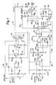
- An energization circuit 20 ( Figure 2) for activating the resistive element 10 includes an energization input 22 shown schematically coupled to the heating element 10.
- a control module 30 ( Figure 3) is mounted to the motor vehicle dashboard within convenient reach of the motor vehicle operator. Both the energization circuit 20 and the control module 30 are coupled to an ignition switch input 32 that energizes both the circuit 20 and control module 30 whenever the ignition key is switched on. Typically, this ignition input carries a regulated 12 volt signal from the vehicle battery.
- the control module 30 includes a combined switch/potentiometer control unit 34.
- a switch 34a can be opened and closed by the vehicle operator to activate and deactivate the heated seat option.
- a variable resistor 34b of the control switch unit 34 allows an adjustment of the heated seat temperature by the adjustment of a resistance.
- the ignition signal input 32 is high (+12v)
- a light bulb 36 coupled across the ignition signal and autombile ground is energized to illuminate the switch 34.
- the switch contact 34a is closed, the 12 volt ignition signal at the input 32 is coupled to an output 40 labelled "switch output" in Figure 3. This switch output is therefore a 12 volt regulated signal which is input to the energization circuit 20 when the switch 34a is closed.
- the voltage at the input 40 is coupled across a combination of a resistor and a zener diode 42 having a break down voltage of approximately 16 volts.
- An output labelled VCC in Figure 2 therefore follows the switched ignition voltage 40 unless this input exceeds 16 volts at which point the zener doide 42 breaks down and regulates the VCC voltage to 16 volts.
- the VCC signal is used to energize those remaining components of the energization circuit 20 that require an external power source.
- the voltage at the input 40 is also coupled to a diode 44 which prevents negative transients from reaching the circuit 20. Specifically, the diode 44 prevents those transients from reaching two switching transistors 46, 48.
- the voltage at the input 40 in combination with the biasing resistors coupled to the two transistors 46, 48 turns on the transistor 48 causing current to flow through a relay coil 50 coupled to the collector of the transistor 48. Energization of this coil 50 closes a relay contact 52 and couples the ignition signal input 32 to the resistive element 10. The ignition voltage therefore energizes the heated seat whenever the relay contact 52 is closed.
- a negative side of the resistive heating element 10 is coupled to a 220 ohm resistor 60 and a field effect transistor 62 which together form a parallel path to ground for the energizing signal from the ignition 32.
- the current through the resistive heating element 10 depends upon the status of the field effect transistor 62. When this transistor is rendered nonconductive, it presents a high impedance path to the ignition voltage and a low level quiescent current through the heating element 10 is produced by the ignition voltage applied across the series combination of the resistive heating element 10 and the resistor 60.
- the resistor 60 is essentially bypassed and the transistor 62 forms a low resistance path to ground so that current through the heating element 10 increases. Under these circumstances high current passes through the heating element 10 and the seat 12 is heated.
- a conductor 63 connected at the juncture of the resistive heating element 10 and the resistor 60 is coupled to a comparator amplifier 66 through a resistor 64.
- An output 66a from the comparator amplifier 66 is high or low depending upon the relative size of the two inputs to the amplifier 66.
- a second input (at a noninverting input to the amplifier) labelled CONTROL in Figures 2 and 3 is controlled by the variable resistor 34b in the control module 30.
- variable resistor 34b is coupled to the input 22 which is energized by the ignition input 32 whenever the relay contact 52 ( Figure 2) closes.
- an adjustable control knob coupled to the variable resistor 34b, the motor vehicle operator raises and lowers the CONTROL input voltage to the amplifier 66 and accordingly raises and lowers a reference voltage to control the point at which the output 66a changes state.
- This knob is labeled with temperature indicators to inform the motor vehicle operator which direction the knob must be turned to raise or lower the seat temperature.
- the voltage input to the amplifier 66 from the negative side of the resistive heating element 10 is higher than the CONTROL input to the comparator amplifier 66. This produces a low signal at the ampli bomb output 66a which discharges a capacitor 72 through the series combination of a diode 74 and resistor 76.
- the capacitor 72 discharges with a time constant dependent upon the capacitance of the capacitor 72 and a resistance of the resistor 76.
- the voltage on the capacitor 72 is coupled to an input 80i of an exclusive OR gate 80.
- the output 80a from the gate 80 is coupled to a second exclusive OR gate 82.
- These gates in combination act as an inverter circuit so that a low signal at the input to the first gate 80 from the capacitor 72 causes a high signal at the output 82a of the second exclusive OR gate 82.
- the output 82a from the second exclusive OR gate 82 is coupled to a gate input 62g of the field effect transistor 62. A high signal at the gate input 62g turns on the field effect transistor 62 and shorts the resistor 60 to increase the current passing through the heating element 10.
- the transistor 62 When the transistor 62 is rendered conductive, the voltage at the inverting input to the comparator amplifier drops below the CONTROL input.
- the output 66a goes high and the capacitor 72 charges through a resistor 84.
- the capacitor 72 charges at a rate determined by the RC time constant of the resistor 84 and capacitor 72 and is slower than the discharge rate of the capacitor 72.
- a feedback resistor 85 connects the gate input 80i to the gate output 80a.
- the resistor 85 provides hysterisis to the operation of the gate 80.
- the crossover voltage of the gate input 80i is typically approximately VCC ⁇ 2.
- the transistor 62 cycles on and off the heating element 10 heats up and due to its positive coefficient of resistance, the voltage across the resistance element 10 drops. As the element's resistance drops the voltage at the junction between the heating element 10 and resistor 60 drops below the reference or CONTROL input to the amplifier 66 with the transistor 62 non-conductive and the amplifier output 66a remains high. This maintains the charge on the capacitor 72 so that the inverter formed from the combination of the two exclusive OR gates 80, 82 keeps the transistor 62 turned off.
- the quiescent or low level current through the heating element 10 is defined by the voltage across the heating element 10 and series connected resistor 60.
- the motor vehicle operator can open the switch 34a once the seat has been heated to remove even this low level current from the resistive heating element 10 but the heating affects with the switch 34a closed are minimal.
- two light emitting diodes 110, 112 indicate the operating condition of the energization circuit 20.
- a first light emitting diode 110 is coupled across the output from the relay switch 52 to indicate when the resistive element 10 is energized.
- a second light emitting diode 112 is coupled in parallel to the resistive heating element 10 and is forward biased to emit light only when the transistor 62 conducts. Stated another way, when the transistor 62 is not conducting, the voltage drop across the resistive heating element is too small to cause this second light emitting diode 112 to emit light.
- Two additional exclusive OR gates 120, 122 ( Figure 2) check for a short circuit condition of either the transistor 62 or the heating element 10.
- the exclusive OR gate 120 has two inputs 124, 126. One input 124 is coupled to the gate input 62g of the transistor 62 through a resistor 128. A second input 126 is coupled to the junction between the heating element 10 and the resistor 60. In the event of a short circuit of the transistor 62 both inputs 124, 126 go low. This forces the output of the exclusive OR gate 120 low which also forces the output from the exclusive OR gate 122 low.
- the gate 122 in combination with a diode 130 and capacitor 132 latch the output signal from the gate 120. The output from the gate 122 is coupled to the base input of the transistor 46.
- a low signal at the base of the transistor 46 turns that transistor on, raising the voltage at that transistor's collector, causing a base input to the transistor 48 to turn off the second transistor 48.
- the relay coil 50 is de-energized and the normally opened relay contact 52 opens.
- a short circuit across the heating element 10 is also sensed and used to open the relay contact 52.
- a short across the heating element 10 at a time when the field effect transistor 62 is on means both inputs 124, 126 to the exclusive OR gate 120 are high.
- the output from the gate 120 then goes low as does the output from the gate 122. This turns on the transistor 46 to bias the transistor 48 off and open the relay contact 52.
- a low output from the gate 122 not only de-energizes the heating element 10 but turns off the transistor 62 by grounding the gate input 62g through a diode 140.
- the short circuit protection prevents high, potentially dangerous currents from developing in the heating element 10. These high currents could potentially damage the circuit 20 and could also cause the seat 12 to catch on fire.
- Two zener diodes 142, 144 are series coupled across the gate input 62g of the transistor 62 and the juncture of the heating element 10 and resistor 60.
- the diode 142 limits the voltage across the gate of the transistor 62 to 7.5 volts.
- Transient protection for the transistor 62 is provided by the diode 144 which has a breakdown voltage of 47 volts.
- the comparator amplifier 66 is proteced against transients by a resistor network 150 coupled to the non-inverting comparator input.
- the network 150 allows the voltage output from the variable resistor 34b to control the input to the comparator while preventing transients from reaching the comparator amplifier 66.
- An alternate transient suppression circuit is illustrated in Figure 4. In the alternate circuit the resistor network 150 ( Figure 2) is replaced with two diodes 152, 154 which block transients from reaching the comparator amplifier.
- the status of the gate input 62g determines whether the heating element 10 carries a high level or quiescent current.
- the gate input 62g is in turn controlled by the voltage across the resistor 60 which as noted previously depends on the resistance and therefore temperature of the heating element 10.
- the transistor 62 cycles on and off at a rate controlled by the RC time constant of the capacitor 72 and resistor 84 until the heating element 10 reaches a reference temperature controlled by the operator adjusted CONTROL input to the comparator 66. When this occurs the transistor 62 is turned off until the heating element temperature again falls below the reference.
Abstract
Description
- The present invention relates to a control for energizing a heating element in a motor vehicle seat.
- Electronically energized heated seats are now increasingly available in motor vehicles. The seat warms a motor vehicle operator before the motor vehicle's heating system becomes effective. A typical automobile heating system can take five to ten minutes after the engine begins running before the thermostat opens. A heating element embedded within a seat starts to heat the motorist as soon as current flows through the heating element. A heated seat option may include resistive elements embedded within only the driver seat, or in some instances both the driver and passenger seat.
- One control system primarily designed for use in controlling the actuation or energization of a heated seat is disclosed in U.S. Patent No. 4,546,238 to Ahs. The control system disclosed in this patent utilizes the fact that the resistance of the resistive heating element changes with temperature. By monitoring a voltage signal generated across the resistance element, the temperature of the resistance element is determined. Comparator circuits in the control system energize and de-energize the resistive heating element to maintain the heating element temperature within a control range.
- One potential problem that appears to have been overlooked in prior art heated seat systems is protection against electrical short circuits. A short in the control circuit of such a system can overheat the circuit and cause permanent damage. A large overcurrent might even cause the vehicle seat to catch on fire. Over current sensing and transient protection to prevent circuit damage due to high voltage spikes are necessary features in a reliable, safe heated seat system.
- It is one object of the invention to provide a reliable, safe, and inexpensive control system for electronically energizing a resistive heating element in a motor vehicle seat.
- A heating element control system constructed in accordance with the invention includes an energizing circuit coupled to a motor vehicle ignition switch to couple an energizing voltage across a heating element. A sensor senses the temperature of the heating element and generates a control signal output related to the temperature. A switch coupled to the control signal output controls current through the heating element as a function of the temperature of the heating element. Additionally a failure detection or sensing circuit de-energizes the heating element in the event of a malfunction in the control system.
- One malfunction that is sensed is a short circuit resulting in the energization signal from the ignition switch bypassing the heating element. This malfunction will cause the control system to overheat. An additional failure would be a short circuit in the control system so that the ignition signal is applied across the heating element at all times. This malfunction can result in high currents that dissipate excessive heat and may damage or even ignite the vehicle seat. High voltage transients that can exist in a vehicle ignition system disrupt or damage the control system. These transients are sensed and intercepted.
- In a preferred embodiment of the invention, the switch element comprises a transistor which is biased on and off in a manner dependent upon the temperature of the resistive heating element. So long as the resistive heating element is below a set point temperature, controlled by the motor vehicle operator, the transistor cycles on and off energizing the heating element. The resistive heating element has a positive co-efficient that causes the heating element resistance to rise as the temperature rises. By monitoring this resistance, a sensing circuit controls the bias on the transistor as the temperature of the heating element rises and falls above and below the set or control temperature. When the heating element is heating up and transmitting energy to the seat in the form of joule heating energy, the transistor is cycled on and off at a frequency controlled by a timing circuit interposed between the transistor and the sensing circuit.
- A control module mounted to a vehicle dashboard includes a light for illuminating the control system, a switch for actuation of the control system by the vehicle operator, and a variable control for adjusting a set or control temperature of the heated seat. In addition, light emitting diodes are utilized to apprise the vehicle operator of the status of the control and in particular indicate those intervals in which the resistive heating element is carrying a high current and transmitting heat to the seat.
- From the above it is appreciated that one object of the invention is a new and improved control system for energizing a heated seat heating element. This and other objects and advantages of the invention will become better understood from a detailed description of a preferred embodiment of the invention discussed below in conjunction with the accompanying drawings.
-
- Figure 1 is a perspective view of a motor vehicle seat having an embedded resistive heating element;
- Figures 2 and 3 are schematic diagrams of a control system for energizing the resistive heating element of Figure 1; and
- Figure 4 depicts an alternate control system schematic.
- Turning now to the drawings, Figure 1 shows a automobile seat having a
resistive element 10 embedded within theseat 12. During periods of cold weather, the driver may actuate the heated seat to cause current to flow through theresistive element 10 and warm the seat prior to the automobile heater becoming effective. - An energization circuit 20 (Figure 2) for activating the
resistive element 10 includes anenergization input 22 shown schematically coupled to theheating element 10. A control module 30 (Figure 3) is mounted to the motor vehicle dashboard within convenient reach of the motor vehicle operator. Both theenergization circuit 20 and thecontrol module 30 are coupled to anignition switch input 32 that energizes both thecircuit 20 andcontrol module 30 whenever the ignition key is switched on. Typically, this ignition input carries a regulated 12 volt signal from the vehicle battery. - The
control module 30 includes a combined switch/potentiometer control unit 34. Aswitch 34a can be opened and closed by the vehicle operator to activate and deactivate the heated seat option. A variable resistor 34b of thecontrol switch unit 34 allows an adjustment of the heated seat temperature by the adjustment of a resistance. When theignition signal input 32 is high (+12v), alight bulb 36 coupled across the ignition signal and autombile ground is energized to illuminate theswitch 34. When theswitch contact 34a is closed, the 12 volt ignition signal at theinput 32 is coupled to anoutput 40 labelled "switch output" in Figure 3. This switch output is therefore a 12 volt regulated signal which is input to theenergization circuit 20 when theswitch 34a is closed. - The voltage at the
input 40 is coupled across a combination of a resistor and azener diode 42 having a break down voltage of approximately 16 volts. An output labelled VCC in Figure 2 therefore follows the switchedignition voltage 40 unless this input exceeds 16 volts at which point thezener doide 42 breaks down and regulates the VCC voltage to 16 volts. The VCC signal is used to energize those remaining components of theenergization circuit 20 that require an external power source. - The voltage at the
input 40 is also coupled to adiode 44 which prevents negative transients from reaching thecircuit 20. Specifically, thediode 44 prevents those transients from reaching twoswitching transistors input 40 in combination with the biasing resistors coupled to the twotransistors transistor 48 causing current to flow through arelay coil 50 coupled to the collector of thetransistor 48. Energization of thiscoil 50 closes arelay contact 52 and couples theignition signal input 32 to theresistive element 10. The ignition voltage therefore energizes the heated seat whenever therelay contact 52 is closed. - As seen in Figure 2, a negative side of the
resistive heating element 10 is coupled to a 220ohm resistor 60 and afield effect transistor 62 which together form a parallel path to ground for the energizing signal from theignition 32. The current through theresistive heating element 10 depends upon the status of thefield effect transistor 62. When this transistor is rendered nonconductive, it presents a high impedance path to the ignition voltage and a low level quiescent current through theheating element 10 is produced by the ignition voltage applied across the series combination of theresistive heating element 10 and theresistor 60. When thetransistor 62 is rendered conductive, however, theresistor 60 is essentially bypassed and thetransistor 62 forms a low resistance path to ground so that current through theheating element 10 increases. Under these circumstances high current passes through theheating element 10 and theseat 12 is heated. - A
conductor 63 connected at the juncture of theresistive heating element 10 and theresistor 60 is coupled to acomparator amplifier 66 through aresistor 64. An output 66a from thecomparator amplifier 66 is high or low depending upon the relative size of the two inputs to theamplifier 66. A second input (at a noninverting input to the amplifier) labelled CONTROL in Figures 2 and 3 is controlled by the variable resistor 34b in thecontrol module 30. - The variable resistor 34b is coupled to the
input 22 which is energized by theignition input 32 whenever the relay contact 52 (Figure 2) closes. By adjusting the setting of an adjustable control knob coupled to the variable resistor 34b, the motor vehicle operator raises and lowers the CONTROL input voltage to theamplifier 66 and accordingly raises and lowers a reference voltage to control the point at which the output 66a changes state. This knob is labeled with temperature indicators to inform the motor vehicle operator which direction the knob must be turned to raise or lower the seat temperature. - If the temperature of the
heating element 10 is below a desired seat temperature when the ignition switch is closed, the voltage input to theamplifier 66 from the negative side of theresistive heating element 10 is higher than the CONTROL input to thecomparator amplifier 66. This produces a low signal at the ampli fier output 66a which discharges a capacitor 72 through the series combination of adiode 74 andresistor 76. The capacitor 72 discharges with a time constant dependent upon the capacitance of the capacitor 72 and a resistance of theresistor 76. - The voltage on the capacitor 72 is coupled to an
input 80i of an exclusive ORgate 80. Theoutput 80a from thegate 80 is coupled to a second exclusive ORgate 82. These gates in combination act as an inverter circuit so that a low signal at the input to thefirst gate 80 from the capacitor 72 causes a high signal at theoutput 82a of the second exclusive ORgate 82. Theoutput 82a from the second exclusive ORgate 82 is coupled to agate input 62g of thefield effect transistor 62. A high signal at thegate input 62g turns on thefield effect transistor 62 and shorts theresistor 60 to increase the current passing through theheating element 10. - When the
transistor 62 is rendered conductive, the voltage at the inverting input to the comparator amplifier drops below the CONTROL input. The output 66a goes high and the capacitor 72 charges through aresistor 84. The capacitor 72 charges at a rate determined by the RC time constant of theresistor 84 and capacitor 72 and is slower than the discharge rate of the capacitor 72. - A
feedback resistor 85 connects thegate input 80i to thegate output 80a. Theresistor 85 provides hysterisis to the operation of thegate 80. As the capacitor 72 discharges a lower capacitor voltage is needed to cause thegate 80 output to change state than is needed when the capacitor is charging. This is because when the capacitor 72 discharges, theresistor 85 tends to pull up the voltage on theinput 80i and when the capacitor 72 is charging theresistor 85 tends to diminish the voltage at theinput 80i. The crossover voltage of thegate input 80i is typically approximately VCC ÷ 2. As the capacitor 72 charges, it must charge to a value of (VCC ÷ 2) + 10% to bring theinput 80i to VCC ÷ 2. As the capacitor 72 discharges, it must discharge to a value of (VCC ÷ 2)-10% to drop theinput 80i to VCC ÷ 2. - As the
transistor 62 cycles on and off theheating element 10 heats up and due to its positive coefficient of resistance, the voltage across theresistance element 10 drops. As the element's resistance drops the voltage at the junction between theheating element 10 andresistor 60 drops below the reference or CONTROL input to theamplifier 66 with thetransistor 62 non-conductive and the amplifier output 66a remains high. This maintains the charge on the capacitor 72 so that the inverter formed from the combination of the two exclusive ORgates transistor 62 turned off. - The quiescent or low level current through the
heating element 10 is defined by the voltage across theheating element 10 and series connectedresistor 60. The motor vehicle operator can open theswitch 34a once the seat has been heated to remove even this low level current from theresistive heating element 10 but the heating affects with theswitch 34a closed are minimal. - Returning to Figure 3, two
light emitting diodes energization circuit 20. A firstlight emitting diode 110 is coupled across the output from therelay switch 52 to indicate when theresistive element 10 is energized. A secondlight emitting diode 112 is coupled in parallel to theresistive heating element 10 and is forward biased to emit light only when thetransistor 62 conducts. Stated another way, when thetransistor 62 is not conducting, the voltage drop across the resistive heating element is too small to cause this secondlight emitting diode 112 to emit light. - Two additional exclusive OR
gates 120, 122 (Figure 2) check for a short circuit condition of either thetransistor 62 or theheating element 10. The exclusive ORgate 120 has twoinputs input 124 is coupled to thegate input 62g of thetransistor 62 through aresistor 128. Asecond input 126 is coupled to the junction between theheating element 10 and theresistor 60. In the event of a short circuit of thetransistor 62 bothinputs gate 120 low which also forces the output from the exclusive ORgate 122 low. Thegate 122 in combination with adiode 130 andcapacitor 132 latch the output signal from thegate 120. The output from thegate 122 is coupled to the base input of thetransistor 46. A low signal at the base of thetransistor 46 turns that transistor on, raising the voltage at that transistor's collector, causing a base input to thetransistor 48 to turn off thesecond transistor 48. With thetransistor 48 in a off state, therelay coil 50 is de-energized and the normally openedrelay contact 52 opens. - A short circuit across the
heating element 10 is also sensed and used to open therelay contact 52. A short across theheating element 10 at a time when thefield effect transistor 62 is on means bothinputs gate 120 are high. The output from thegate 120 then goes low as does the output from thegate 122. This turns on thetransistor 46 to bias thetransistor 48 off and open therelay contact 52. - Note that a low output from the
gate 122 not only de-energizes theheating element 10 but turns off thetransistor 62 by grounding thegate input 62g through adiode 140. - The short circuit protection prevents high, potentially dangerous currents from developing in the
heating element 10. These high currents could potentially damage thecircuit 20 and could also cause theseat 12 to catch on fire. - Two
zener diodes gate input 62g of thetransistor 62 and the juncture of theheating element 10 andresistor 60. Thediode 142 limits the voltage across the gate of thetransistor 62 to 7.5 volts. Transient protection for thetransistor 62 is provided by thediode 144 which has a breakdown voltage of 47 volts. - The
comparator amplifier 66 is proteced against transients by a resistor network 150 coupled to the non-inverting comparator input. The network 150 allows the voltage output from the variable resistor 34b to control the input to the comparator while preventing transients from reaching thecomparator amplifier 66. An alternate transient suppression circuit is illustrated in Figure 4. In the alternate circuit the resistor network 150 (Figure 2) is replaced with twodiodes - In operation, the status of the
gate input 62g determines whether theheating element 10 carries a high level or quiescent current. Thegate input 62g is in turn controlled by the voltage across theresistor 60 which as noted previously depends on the resistance and therefore temperature of theheating element 10. Thetransistor 62 cycles on and off at a rate controlled by the RC time constant of the capacitor 72 andresistor 84 until theheating element 10 reaches a reference temperature controlled by the operator adjusted CONTROL input to thecomparator 66. When this occurs thetransistor 62 is turned off until the heating element temperature again falls below the reference. - The present invention has been described with a degree of particularity. It is the intent, however, that the invention include all modifications and alterations of the disclosed design falling within the spirit or scope of the appended claims.
Claims (11)
applying an energization signal across a series combination of the resistive heating element and an impedance device;
sensing the temperature of the resistive heating element by monitoring the resistance of the heating element;
periodically increasing current through the heating element by adding a low impedance path in parallel with the impedance device at a controlled frequency until the temperature of the resistive heating element reaches a control value as indicated by the resistance of the heating element; and
monitoring a voltage at a juncture between the heating element and the impedance device to sense a fault condition and removing the energization signal if a fault condition is sensed.
Applications Claiming Priority (2)
| Application Number | Priority Date | Filing Date | Title |
|---|---|---|---|
| US4961887A | 1987-05-13 | 1987-05-13 | |
| US49618 | 1987-05-13 |
Publications (2)
| Publication Number | Publication Date |
|---|---|
| EP0293100A1 true EP0293100A1 (en) | 1988-11-30 |
| EP0293100B1 EP0293100B1 (en) | 1993-11-03 |
Family
ID=21960778
Family Applications (1)
| Application Number | Title | Priority Date | Filing Date |
|---|---|---|---|
| EP88304084A Expired - Lifetime EP0293100B1 (en) | 1987-05-13 | 1988-05-05 | Electrically heated seat control system |
Country Status (2)
| Country | Link |
|---|---|
| EP (1) | EP0293100B1 (en) |
| DE (1) | DE3885345D1 (en) |
Cited By (1)
| Publication number | Priority date | Publication date | Assignee | Title |
|---|---|---|---|---|
| EP0445905A1 (en) * | 1990-03-02 | 1991-09-11 | Nartron Corporation | Motor vehicle heated seat control |
Citations (6)
| Publication number | Priority date | Publication date | Assignee | Title |
|---|---|---|---|---|
| DE2309104B2 (en) * | 1973-02-23 | 1975-03-06 | Matthey De L'etang, William H., Lausanne (Schweiz) | Circuit arrangement for monitoring the resistance of a heating wire for the electrical heating of shuttering panels or ducts for tension wires in the manufacture of concrete sections |
| GB1432024A (en) * | 1973-07-09 | 1976-04-14 | Waynco | Control circuits |
| DE2757334A1 (en) * | 1977-12-22 | 1979-07-05 | Beurer Gmbh & Co | Heater with temp. control circuit - passing test current through element and measuring voltage drop to determine temp. |
| DE2850859B1 (en) * | 1978-11-24 | 1980-01-17 | Beurer Gmbh & Co | Safety circuit for temperature-controlled, electrical heating or heating devices operated with AC voltage |
| US4477747A (en) * | 1981-10-03 | 1984-10-16 | Kabushiki Kaisha Sankyo Seiki Seisakusho | Lamp circuit for automobile |
| EP0196802A2 (en) * | 1985-03-28 | 1986-10-08 | Wickes Manufacturing Company | Method and apparatus for controlling the operation of a DC load |
Family Cites Families (1)
| Publication number | Priority date | Publication date | Assignee | Title |
|---|---|---|---|---|
| SE442079B (en) * | 1982-02-08 | 1985-11-25 | Tocksfors Verkstads Ab | CIRCUIT FOR CONTROL OF THE TEMPERATURE OF AN ELECTRIC HEATING ELEMENT |
-
1988
- 1988-05-05 DE DE88304084T patent/DE3885345D1/en not_active Expired - Lifetime
- 1988-05-05 EP EP88304084A patent/EP0293100B1/en not_active Expired - Lifetime
Patent Citations (6)
| Publication number | Priority date | Publication date | Assignee | Title |
|---|---|---|---|---|
| DE2309104B2 (en) * | 1973-02-23 | 1975-03-06 | Matthey De L'etang, William H., Lausanne (Schweiz) | Circuit arrangement for monitoring the resistance of a heating wire for the electrical heating of shuttering panels or ducts for tension wires in the manufacture of concrete sections |
| GB1432024A (en) * | 1973-07-09 | 1976-04-14 | Waynco | Control circuits |
| DE2757334A1 (en) * | 1977-12-22 | 1979-07-05 | Beurer Gmbh & Co | Heater with temp. control circuit - passing test current through element and measuring voltage drop to determine temp. |
| DE2850859B1 (en) * | 1978-11-24 | 1980-01-17 | Beurer Gmbh & Co | Safety circuit for temperature-controlled, electrical heating or heating devices operated with AC voltage |
| US4477747A (en) * | 1981-10-03 | 1984-10-16 | Kabushiki Kaisha Sankyo Seiki Seisakusho | Lamp circuit for automobile |
| EP0196802A2 (en) * | 1985-03-28 | 1986-10-08 | Wickes Manufacturing Company | Method and apparatus for controlling the operation of a DC load |
Cited By (2)
| Publication number | Priority date | Publication date | Assignee | Title |
|---|---|---|---|---|
| US5229579A (en) * | 1987-05-13 | 1993-07-20 | Nartron Corporation | Motor vehicle heated seat control |
| EP0445905A1 (en) * | 1990-03-02 | 1991-09-11 | Nartron Corporation | Motor vehicle heated seat control |
Also Published As
| Publication number | Publication date |
|---|---|
| DE3885345D1 (en) | 1993-12-09 |
| EP0293100B1 (en) | 1993-11-03 |
Similar Documents
| Publication | Publication Date | Title |
|---|---|---|
| US5229579A (en) | Motor vehicle heated seat control | |
| US4926025A (en) | Electrically heated seat resistive heating element energization system | |
| US4628235A (en) | Control circuit for motor driver | |
| US6205010B1 (en) | Switch circuit having protection function to interrupt input of control signal | |
| KR100575922B1 (en) | A Motor Vehicle Electrical Heating System | |
| EP0571383A1 (en) | Battery protection system. | |
| US4467386A (en) | Fail-safe sensor circuit | |
| US5190019A (en) | Interlock circuit for de-activating an engine | |
| US5781385A (en) | Method and apparatus for protecting an adjustable impedance element controlling the power supply to an electric motor, in particular in a motor vehicle | |
| JP2001502472A (en) | Electric heater for automobile | |
| US4506137A (en) | Temperature responsive control circuit for electric window de-fogger/deicer heater | |
| US5333105A (en) | Transient voltage protector | |
| US5981918A (en) | Circuit for temperature-dependent regulation of the heating current of seat heaters | |
| EP0142988A2 (en) | Power steering control apparatus | |
| US5184300A (en) | Control apparatus for a vehicle for controlling a device mounted thereon | |
| US5632917A (en) | Electric windshield defroster | |
| EP0293100A1 (en) | Electrically heated seat control system | |
| US6060834A (en) | Protection from overheating of a switching transistor that delivers current to a daytime running light on a vehicle | |
| US4220947A (en) | Headlamp and security alarm control system | |
| US4983897A (en) | Control circuit | |
| US4916287A (en) | Instant heating system for motor vehicles and the like | |
| US4452582A (en) | Independent, self-contained electronic spark ignition recycler | |
| US4454984A (en) | Auxiliary circulation system for vehicle heaters | |
| US2806150A (en) | Poznik | |
| EP0525484B1 (en) | Control circuit for an electrically heated steering wheel in an automotive vehicle |
Legal Events
| Date | Code | Title | Description |
|---|---|---|---|
| PUAI | Public reference made under article 153(3) epc to a published international application that has entered the european phase |
Free format text: ORIGINAL CODE: 0009012 |
|
| AK | Designated contracting states |
Kind code of ref document: A1 Designated state(s): DE SE |
|
| 17P | Request for examination filed |
Effective date: 19890523 |
|
| 17Q | First examination report despatched |
Effective date: 19910808 |
|
| GRAA | (expected) grant |
Free format text: ORIGINAL CODE: 0009210 |
|
| AK | Designated contracting states |
Kind code of ref document: B1 Designated state(s): DE SE |
|
| PG25 | Lapsed in a contracting state [announced via postgrant information from national office to epo] |
Ref country code: SE Effective date: 19931103 Ref country code: DE Effective date: 19931103 |
|
| REF | Corresponds to: |
Ref document number: 3885345 Country of ref document: DE Date of ref document: 19931209 |
|
| PLBE | No opposition filed within time limit |
Free format text: ORIGINAL CODE: 0009261 |
|
| STAA | Information on the status of an ep patent application or granted ep patent |
Free format text: STATUS: NO OPPOSITION FILED WITHIN TIME LIMIT |
|
| 26N | No opposition filed |