EP0293893A2 - Disposable and/or replenishable drug applicators and methods of manufacturing same - Google Patents
Disposable and/or replenishable drug applicators and methods of manufacturing same Download PDFInfo
- Publication number
- EP0293893A2 EP0293893A2 EP88108838A EP88108838A EP0293893A2 EP 0293893 A2 EP0293893 A2 EP 0293893A2 EP 88108838 A EP88108838 A EP 88108838A EP 88108838 A EP88108838 A EP 88108838A EP 0293893 A2 EP0293893 A2 EP 0293893A2
- Authority
- EP
- European Patent Office
- Prior art keywords
- battery
- conductive
- substrate
- drug
- applicator
- Prior art date
- Legal status (The legal status is an assumption and is not a legal conclusion. Google has not performed a legal analysis and makes no representation as to the accuracy of the status listed.)
- Granted
Links
Images


Classifications
-
- A—HUMAN NECESSITIES
- A61—MEDICAL OR VETERINARY SCIENCE; HYGIENE
- A61N—ELECTROTHERAPY; MAGNETOTHERAPY; RADIATION THERAPY; ULTRASOUND THERAPY
- A61N1/00—Electrotherapy; Circuits therefor
- A61N1/02—Details
- A61N1/04—Electrodes
- A61N1/0404—Electrodes for external use
- A61N1/0408—Use-related aspects
- A61N1/0428—Specially adapted for iontophoresis, e.g. AC, DC or including drug reservoirs
- A61N1/0432—Anode and cathode
- A61N1/044—Shape of the electrode
-
- A—HUMAN NECESSITIES
- A61—MEDICAL OR VETERINARY SCIENCE; HYGIENE
- A61N—ELECTROTHERAPY; MAGNETOTHERAPY; RADIATION THERAPY; ULTRASOUND THERAPY
- A61N1/00—Electrotherapy; Circuits therefor
- A61N1/02—Details
- A61N1/04—Electrodes
- A61N1/0404—Electrodes for external use
- A61N1/0408—Use-related aspects
- A61N1/0428—Specially adapted for iontophoresis, e.g. AC, DC or including drug reservoirs
- A61N1/0432—Anode and cathode
- A61N1/0436—Material of the electrode
-
- A—HUMAN NECESSITIES
- A61—MEDICAL OR VETERINARY SCIENCE; HYGIENE
- A61N—ELECTROTHERAPY; MAGNETOTHERAPY; RADIATION THERAPY; ULTRASOUND THERAPY
- A61N1/00—Electrotherapy; Circuits therefor
- A61N1/02—Details
- A61N1/04—Electrodes
- A61N1/0404—Electrodes for external use
- A61N1/0408—Use-related aspects
- A61N1/0428—Specially adapted for iontophoresis, e.g. AC, DC or including drug reservoirs
- A61N1/0448—Drug reservoir
Definitions
- This invention relates to disposable as well as replenishable transdermal drug applicators which are electrically powered, and to methods for making such constructions.
- a complete electrical circuit is made through the skin once the drug applicator is adhered thereto, whereby at least one physico/chemical mass transfer phenomenon takes place causing the drug or medicament to migrate through the skin.
- transdermal drug applicator 10 which is adhered to the skin 11 comprising an outer cover 12 with a centrally raised portion 14 and a peripheral sealed area or lip portion 16.
- a transdermal drug applicator is of the replaceable type having provision for connection to a reusable power supply 18 which may be, if desired, part of a wrist watch mounting having optionally a programmable control device such as more particularly described and claimed in said aforementioned earlier filed patent application, Serial No. PCT/US85/01075, filed June 10, 1985.
- Power supply 18 comprises a suitable disc battery 20 having electrodes or terminals on opposite sides thereof.
- One battery electrode is electrically connected to current conditioning or electronic conditioning means 22 and by means of suitable snap-on or other type of mechanical connectors (silver-plated Velcro connections manufactured by Velcro Corporation of America) or by conductive and reusable adhesives; and the battery electrodes are in turn connected to conductors 24, 24′ extending from drug reservoirs 26, 28,which are also indicated as reservoirs B and C, respectively.
- the conductors 24, 24′ are flexible, suitably conductive surfaces or coatings on a flexible plastic substrate 30 which is non-conductive, impermeable, stable and otherwise compatible with drugs, adhesives, the skin and any other materials from which the device is fabricated.
- Each conductor 24, 24′ with its substrate 30 forms a seamless, one-piece, folded member.
- the plastic substrate 30 and conductive surfaces bring the electrical contacts 24, 24′ to the top side of the drug applicator where the electrical connections are to be made with the reusable power supply 18.
- the adhesive coating 32 on the inside (and topside) of the plastic substrate 30 secures together the mating surfaces as well as the overlapping edge or end 34 which is provided with a suitable slot or aperture 36 representing a nest or well area for receiving the power supply 18 and its electrical connectors.
- a small peripheral clearing 38 about the aperture 36 represents an insulating guard area to preclude any possibility of shorting out.
- the lower electrode 40 and upper electrode 42 of the battery directly or indirectly make elctrical contact with conductors 24, 24′.
- Suitable insulating material 44 surrounds the current or electronic conditioning means 22 and suitable insulating material "A", which forms the dam separating the drug reservoirs 26, 28 and provides the end seals for not only the side of longitudinal edges but also for the transverse edges of the transdermal drug applicator.
- Conformable cover 12 protects the entire device and may be suitably of a skin tone or color and the like appearance.
- the cover need not be conductive as the lip portion merely acts as a peripheral seal and not a return electrode.
- the invention is also applicable to drug applicators of the "matted" frame construction where the lip portion acts as the return or inactive electrode. In such case, then the conformable cover must also be conductive.
- Electro-kinetic mass transfer processes require an electric power source, and in the cse of electrophoresis an ionized drug migrates from the drug applicator patch through the skin and into the blood stream, whereas in the case of electroosmosis, a fluid carrier, such as water is likewise transported across the skin and into the blood stream carrying along with it any and all dissolved constituents (ionized drugs or otherwise). Either or both of these two physiochemical phenomena may jointly work together or independently in transdermally carrying a drug or drugs across the skin in a desired dosage release and/or relatively steady pattern.
- the application or an electric field across the skin greatly enhances the skin permeability to various drugs.
- a suitable release liner 48 Prior to the attachment to the skin, a suitable release liner 48 is removed leaving the two drug reservoirs, insulating dam and peripheral seals free to adhere to the skin.
- the power supply 18 is supported by a like plastic substrate 50 which is in turn suitably adhesively secured by adhesive 51 to a small conformal cover 52 which neatly covers over and seals off the apertured area where the electrical connections are made. This ensures that the device can be worn at all times; such as in the rain or in the shower or bath.
- the reusable power supply 18 may be part of a wrist watch 54, as shown in Figure 2A, having a programmable computer with concentric conductive adhesive connectors 40, 42, such as previously disclosed in said earlier patent filing with like electrical connections and mechanical securement being provided where needed to achieve such packaged construction.
- the main difference between the disposable drug applicators shown in Figures 2 and 2A is that the conformal cover means 12′ of Figure 2A is coated with an adhesive layer 13. Such adhesive layer 13 allows removal of the drug applicator and replacement same as adhesive 51 in Figure 2.
- the drug reservoirs may be suitable gel layers which can be rolled or otherwise applied to webbed substrate 48, discussed previously,fed from endless rolled sheet material while being separated between reservoirs and about their extreme edges by applied occlusive adhesive dams.
- the dams are identified by the Letters A and the drug reservoirs are marked with the Letters B representing negative and C representing positive.
- the "quilt" type pattern where multiple drug reservoirs are employed can be fabricated by repetitive operative steps using a silk screen printing or transfer process.
- the substrate is coated with a suitable release agent 49, such as silicone and when the sub-assembly is combined into a complete transdermal drug applicator or patch, the substrate in effect becomes the release liner.
- Figures 6-7 illustrate the assembly of two drug applicator sub-assemblies.
- an optional reinforcing web or vail-like material (scrim) 62 may be used to reinforce the gel "drug" reservoirs.
- One embodiment uses an open cell foam which is impregnated in different areas with gel drug reservoirs surrounded by occlusive adhesive dam penetrating the same open cell foam.
- Such a structure allows the construction of a thick replaceable drug reservoir in which the gel will maintain its integrity during manufacturing, the application to and removal from human skin, as well as to the replacement of exhausted drug reservoirs.
- the open cell foam web may be suitably attached to a release liner, then provided with occlusive adhesive dams which completely penetrate the full thickness of the open cell foam, thus forming or designating the drug reservoir areas which can be subsequently filled in with their respective drug/gel mixtures.
- Figure 7 simply differs in that a semi-permeable membrane 64 is provided between the two sub-assemblies so that upon assembly, drug reservoirs are formed with areas or zones of different drug concentration or composition. Such a type of drug reservoir is noted to have significant advantages during operation of the transdermal device.
- seals 47 can be provided along the semi-permeable membranes at the edges where each reservoir ends by means of heat or by other means to collapse the voids and seal the semipermeable membrane in those areas 47 where the seals are necessary.
- silicone dams could also be used as seals between zones of semi-permeable materials.
- the semi-permeable materials may be preimpregnated with drugs or other chemicals which might be employed.
- the disposable drug applicator 70 shown in Figure 8 comprises an optionally replaceable drug reservoir sub-assembly 72 (any one of Figures 4-7) and a further sub-assembly 74 for the power means and electrical conditining means which assemblies are secured together by suitable conductive adhesives.
- Sub-assembly 74 comprised essentially of battery 20 and current conditioning means 22 and associated reservoir conductors 24, 24′ as best shown in Figure 2.
- the electrical circuit running between the drug reservoirs and through the skin is a loop similar to that of Figure 2, the only difference being the permanent nature of the battery and current/electrical conditioning means in the applicator structure rather than the reusable nature of the Figure 2 embodiment.
- the drug reservoir sub-assembly 72 may be replaced where required.
- the cover means 76 is suitably provided with window means, as is shown, which allows the status of the drug applicator to be observed.
- window means Such indicator means which is observed through the window means is more particularly described in my earlier filed U.S. patent application, Serial No. 660,192, filed October 12, 1984.
- the indicator means 150 is electrically in series with the current conditioning means 22 and conductive surface 90 which powers drug reservoir B.
- the connections of said indicator means 150 to the current conditioning means 90 and the conductive surface are achieved by means of a suitable flexible conductive adhesive, as is shown at the contact joints 152 and 154.
- Figure 9 represents a like kind of disposable drug applicator80having an optionally replaceable drug reservoir sub-assembly 72 illustrated in Figures 8-8A, and a power source or flat layered battery, as well as electrical or current conditioning means 84 sub-assembly which are secured together by suitable conductive adhesives.
- the battery embodies sheet electrodes such as carbon (-) reference number 86 and zinc(+), reference number 88 and the drug reservoir electrodes 90, 90′ which also are thin and flat.
- the battery electrodes 86, 88 are adhesively connected to a plastic substrate 30.
- the webbed material in production is preferably folded along the illustrated longitudinal fold lines, 73,73′,73 ⁇ ,73′′′ (and others may be required depending upon the required number of folds) cut transversely to a predetermined size.
- One carbon electrode 86 which is connected to the drug reservoir electrode 90 forms a battery with the large zinc electrode 88.
- the carbon electrode 86 which is connected to electrode 90 could be made as one unitary element.
- This large zinc electrode 88 is electrically connected to the other carbon electrode 86 by means of the conductive adhesive strip 87 ( Figure 10) at one end thereof, and thus forms a second battery, in series with the first battery,in conjunction with the small zinc electrode 88 which is likewise electrically connected to conductive surface 134 at 87′ or simply with a conductive adhesive strip similar to 87.
- a suitable current or other electronic conditioning means 84 is secured by a conductive adhesive 130 to one of the drug electrode conductive surfaces 90′ having a flexible plastic substrate 30 and is also electrically connected to one of the battery electrodes, shown at 100 by means of an optional conductive indicator 150′.
- a window means such as a transparent area 156 of the cover 12 or an opening in said cover allows the viewing of an optional indicator 150′. In such case, the indicator 150′replaces the conductive connector.
- the last battery electrode, shown at 88 is electrically connected to the other drug electrode conductive surface 90 to form a complete electrical loop between the two drug reservoirs and through the skin.
- a suitable battery electrode element 131 impregnated with a gelled battery electrolyte is inserted between the carbon and zinc electrodes prior to folding, and the peripheries of the battery compartments are suitably sealed at 132 to prevent electrolyte leakage.
- the drug reservoirs are also optionally removable if desired, as was shown in Figures 8-8A.
- some adhesives employed may also be conductive while in other instances it is inherent that the adhesive has no other function than to secure together objects so it need not necessarily be conductive and in some cases it must not be conductive or a short circuit would occur.
- the voltage of the battery will determine the numbers of carbon and zinc electrodes required, and such voltage can vary depending upon the applications. Although only carbon/zinc batteries are illustrated, other type batter cells could be made in a similar manner.
- a current limiting resistor, in series with the battery can be manufactured by controlling the resistance of the conductive surfaces.
- Such use would make the device fail safe and could provide current regulation in addition to or instead of solid state conditioning means 22 of Figure 8. Therefore, if the current conditioning means 22 of Figure 8 short circuits this resistor will limit the current to a safe value or level.
- Drug applicator 200 includes a pair of optionally replaceable drug reservoirs B and C, and a power source, such as twelve button batteries 202A-L, all enclosed by an outer cover 204, which is preferably aluminized.
- Button batteries 202A-L are arranged in two units 206 and 208, each including five batteries, namely, batteries 202A-E and 202F-L, respectively.
- Battery unit 206 is located proximately above reservoir B, which is negative in charge, and battery unit 206 is located proximately above reservoir C, which is positive in charge.
- Batteries 202A-L can vary in number and voltage in accordance with a particular design for a particular drug or drugs contained in the reservoirs. Each battery illustrated is typically 1.5 volts, but the system can include more or fewer batteries each having a lesser or greater voltage. Alternatively, flat batteries typically approximately 1.5mm in thickness can be used in lieu of the button batteries.
- Button batteries 202A-L have vertically opposed terminals. The charges of the topside terminals of button batteries 202A-L are shown in Figure 1.
- a flexible plastic substrate 210, such as "Mylar" has electroconductive coating 212, preferably an electroconductive graphite paint, applied to one side and an adhesive layer 214 applied to the opposite side.
- Substrate 210 is non-conductive, impermeable, stable, and compatible with drugs, adhesives, the skin, and materials from which drug applicator 200 is fabricated.
- Substrate 210 has end portions 216B and 216C which are each underfolded once in an outward, or downward, direction as viewed in Figure 10, toward reservoirs B and C so that a topside and a bottomside portion is at each end with conductive paint 212 being in electrical contact with the inner side of reservoirs B and C at end portions 216B and 216C.
- Conductive paint 212 covers two separate areas of substrate 210 each in contact with end portions 216B and 216C so that there is no direct electrical connection between reservoirs B and C by way of end portions 216B and 216C.
- Adhesive layer 214 adheres to adhesive layer 214 at the end portions 216B and 216C.
- Conductive paint 212 which covers the entire undersurface of end portions 216B and 216C of substrate 210, follows the folded contour of substrate 210 inwardly, or upwardly, so that paint 212 is on the top surface side of the main portion of substrate 210 so that paint 212 is in electrical contact with the bottomside terminals of batteries 202A-L.
- paint 212 is configured as printed circuits 218B and 218C, shown in Figure 11, joining the positive and negative bottomside terminals of the batteries.
- Printed circuits 220B and 220C which connect in series the positive and negative topside terminals of batteries 202A-L at battery units 206 and 208, are placed on the underside of a stiff plastic sheet 222, which extends over all batteries 202A-L.
- a current conditioner 224 is positioned proximate battery unit 208 is connected in series with batteries 202A-L by a printed circuit 226 on the undersurface of plastic sheet 222.
- Electroconductive adhesive paste drops 228 are preferably used to ensure good electrical connections between the terminals of the batteries and printed circuits 218B and 218C and 220B and 220C. Electroconductive paste drops 228 are also used at the opposed sides of current conditioner 224. An electrical circuit thus exists between reservoirs B and C through the skin upon placement of applicator 200 upon the skin and through batteries 202A-L and current conditioner 224.
- a pair of perforated plastic liners 230A and 230B are preferably placed on either side of batteries 202A-L primarily to inhibit any spreading of drops 228. Perforations in liners 230 provide access for drops 228.
- a spacer such as foam spacer 232, is preferably positioned between the pair of liners 230A and 230B.
- a heat sealable plastic liner 234 is positioned on the underside of applicator 200 and is connected to the periphery of cover 204.
- a skin adhesive 236 is placed on the underside of liner 234.
- a removable release liner (not shown) is ordinarily placed on the underside of liner 234 and is removed prior to use of the applicator.
- Sealed edges in the form of sealed side walls 238 are disposed about the periphery of reservoirs B and C in order to prevent passage of the drug or drugs from the reservoirs.
- the sealed side walls 238 may be formed, if desired, by heat sealing through liner 234 and through the drug reservoir material to substrate 210. Alternately, walls 238 can be formed by using a suitable material such as silicon adhesive to seal the peripheral reservoir edges to affix liner 234 to drug reservoirs B and C.
- Drug applicator 200 can be assembled in steps from the components described above. These components are illustrated in Figure 13 in an exploded perspective view of a drug applicator 242 analogous to drug applicator 200.
- the assembly of applicator 242 comprises the following steps:
- Flat layered batteries such a batteries 86, 88 illustrated in Figures 9 and 10 may be substituted for button batteries 202A-L illustrated in Figures 11 and 12 and button batteries 248-C illustrated in Figure 13.
- the production method illustrated in Figure 10 can be used for applicators 200 and 242.
- Reservoirs B and C are enclosed at their sides by heat-sealed walls 238. Either one or both reservoirs may be used, that is, a non-drug electrode may be substituted for either reservoir.
- a pair of breathing windows 240 that extend transversely through the entire drug applicator 242 between battery units 206 and 208 provide a passage for evaporated sweat that may form on the skin.
- the two battery units 206 and 207 in Figures 11 and 12 and the two battery units 250 and 252 in Figure 13 may be one battery unit positioned on the side of either drug reservoir B or C.
- FIG 14 illustrates transdermal drug applicator 300 having the same arrangement of elements as described for dug applicator 200 described earlier in relation to Figure 12 except for a flat, flexible substrate 302 made of plastic such as "Mylar" or other similar material.
- Substrate 210 is non-conductive, impermeable to the passage of liquid, stable, and compatible with drugs, adhesives, skin, and materials from which drug applicator 300 is fabricated.
- Substrate 302 has top and bottom electroconductive coatings 304A and 306A applied to the top and bottom surfaces, respectively, of substrate 302 in the vicinity of reservoir B and further has top and bottom electroconductive coatings 304B and 306B applied to the top and bottom surfaces, respectively, of substrate 302 in the vicinity of reservoir C.
- Coatings 304A, 306A, 304B, and 306B are preferably made of an electroconductive material such as carbon, preferably graphite.
- the graphite can be in the form of a graphite paint.
- Top conductive coating 304A extends to electrical connection with batteries 202A and 202F, but also is representative of top electrical conductive connections between all batteries 202A-F.
- top conductive coating 304B extends to electrical connection with batteries 202A and 202F, but also is representative of top electrical conductive connections between all batteries 202G-K.
- Bottom coating 306A is in electrical connection with reservoir B and bottom coating 306B is in electrical connection with reservoir C.
- FIG 16 illustrates an enlarged detail view of substrate 302 with top and bottom coatings 304A and 306A joined in electrical connection by top and bottom electroconductive joining strips 308 and 310, respectively.
- Top joining strip 308 includes a flexible top substrate strip 312 made of the same material as substrate 302 and an electroconductive top coating strip 314 made of the same electroconductive material as coatings 304A and 306A.
- Top coating strip 314 is in electrical connection with top conductive coating 304A.
- bottom joining strip 310 includes a flexible bottom substrate strip 316 made of the same material as substrate 302 and an electroconductive bottom coating strip 318 made of the same electroconductive material as coatings 304A and 306A.
- Bottom coating strip 318 is in electrical connection with bottom conductive coating 306A.
- Substrate 302 defines a circular hole 320A, which extends transversely through substrate 302 and also through top and bottom conductive coatings 304A and 306A.
- Top and bottom joining strips 308 and 310 are secured to the top and bottom coating strip 314 and 318, respectively, by top and bottom adhesives 322 and 324, respectively.
- Top and bottom joining strips 308 and 310 extend into hole 320A where their respective top and bottom coating strips 314 and 318 are joined in electrical contact at a juncture preferably held together by an electrically conductive adhesive 326.
- Top and bottom joining strips 308 and 310 along with hole 320A are the same for the electrical connection between top and bottom conductive coatings 304B and 306B at hole 320B illustrated in Figure 14.
- Figure 16 illustrates the assembly of the electrical connection between top and bottom coating strips 312 and 314.
- Top and bottom joining strips 304 and 306 are positioned spaced from top and bottom conductive coatings 304A and 306A of substrate 302 prior to the next steps of pressuring top and bottom joining strips into mutual electrical contact inside of hole 320A and into adhesive connection with top and bottom conductive coatings 304A and 306A.
- FIGS 17 and 18 illustrate another embodiment of a construction and arrangement for connecting top and bottom conductive coatings 304A and 306A into electrical contact.
- a mesh member 328 is positioned over a hole 327 extending through substrate 302 and its top conductive coating 304A.
- Bottom conductive coating 306 extends across hole 327.
- Mesh member is pressed into adhesive contact with top conductive coating 304A around hole 320A and is further pressed into hole 320A into adhesive contact with bottom conductive coating 306A.
- Mesh member 328 has a plurality of mesh holes which are filled with a conductive material 330, such a carbon, which can be graphite, for example.
- top and bottom conductive coatings 304A and 306A are electrically connected by means of conductive material 330. Electrical connection of top and bottom conductive coatings 304B and 306B through hole 304B is of the same arrangement and construction described.
- Figures 19 and 20 illustrate yet another embodiment of a construction and arrangement for connecting top and bottom conductive coatings 304A and 306A into electrical contact.
- substrate 302 and top conductive coating 304A form a plurality of small transverse holes 332 over a cylindrical volume 334.
- Holes 332 are filled with a conductive material 336, such as carbon, which can be graphite, which electrically connects top and bottom conductive coatings 304A and 306A.
- Electrical connection of top and bottom conductive coatings 304B and 306B is of the same construction and arrangement described.
- FIGS 219 and 22 illustrate yet another embodiment of a construction and arrangement for connecting top and bottom conductive coatings 304A and 306A into electrical contact.
- substrate 302 and top conductive coating 304A form a plurality of small transverse transverse slots 338 over a cylindrical volume 340, with slots 338 being of different lateral dimensions so as to stay within the dimensions of volume 340.
- Slots 338 are filled with a conductive material 342, such as carbon, which can be graphite, which electrically connects top and bottom conductive coatings 304A and 306A.
- Electrical connection of top and bottom conductive coatings 304B and 306B is of the same construction and arrangement described.
Abstract
Description
- This invention relates to disposable as well as replenishable transdermal drug applicators which are electrically powered, and to methods for making such constructions. A complete electrical circuit is made through the skin once the drug applicator is adhered thereto, whereby at least one physico/chemical mass transfer phenomenon takes place causing the drug or medicament to migrate through the skin.
- Reference to or disclosure of devices for transdermal delivery of drugs by application of electrical current through the skin of a person or animal are shown in the following United States patents:
385,556 4,243,052
486,902 4,325,367
588,479 4,367,745
2,493,155 4,419,091
2,267,162 4,474,570
2,784,715 4,406,658
3,163,166 4,314,554
3,289,671 4,166,457
3,547,107 4,239,052
3,677,268 4,290,878
4,008,721 4,164,226
4,141,359 4,362,645
4,239,046 4,273,135 - The following foreign patents refer to or disclose transdermal delivery devices:
EPA 0060452
DE 290202183
DE 3225748
EPA 0058920
UK 2104388 -
- Figure 1 is a perspective view, paertially cut away, so as to illustrate the innards of a self- contained drug applicator of the invention;
- Figure 2 is a longitudinal cross-sectional view of the drug applicator of Figure 1, and also illustrating in exploded view a reusable power supply which may be provided with a programmable control and wrist watch mounting;
- Figure 2A is a view similar to Figure 2, but shown perspectively, in which the power supply and the programmable control are contained within a wrist watch mounting having concentric connectors;
- Figure 3 is another perspective view similar to Figure 1, but showing alternate construction having a pair of off-center apertures or slots for the electrical contacts made through the use of a single center aperture so as to enable the mounting of a new drug applicator to the reusable power supply in a keyed or polarized manner.
- Figures 4 and 5 are fragmentary perspective views of typical configurations of drug electrodes/reservoirs provided on endless web substrates fed from rolled stock material, with occlusive adhesive dams separating the drug reservoirs longitudinally, as well as transversely;
- Figures 6 and 7 respectively illustrate diagrammatically typical assemblies of drug electrodes/reservoirs forming larger reservoir means; or forming drug gradient with layers of both high and low drug concentration within reservoirs separated by a semipermeable membrane or reinforcing scrim.
- Figure 8 is a cross-sectional view of a disposable drug applicator with a separate subassemblied power source and electrical conditioning means adhesively assembled along their electrodes to any one typical drug electrode/reservoir assemblies shown in Figures 6-7;
- Figure 8A is a cross-sectional view similar to that shown in Figure 8, but illustrating an alternate drug applicator construction in which the outer conformal cover has window means through which current induced color changes or other visual feedback information can be viewed for verification of status of the drug delivery system, such as drug delivery taking place or having been terminated.
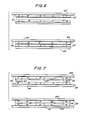
- Figure 9 is a cross-sectional view of an alternate construction having similarly optionally replaceable drug reservoirs (electrodes/reservoirs), and with flat batteries forming a sub-assembly with electrical connections to electronic conditioning means;
- Figure 10 illustrates an endless such substrate fed from rolled stock material upon which is provided thin sheet electrodes for the flat batteries and other rolled, layered materials for forming the power-source sub-assembly shown in Figure 9;
- Figure 11 illustrates a top view embodiment of the drug applicator having the end portions of the substrate folded downwardly and having a number of bottom batteries;
- Figure 12 is a cross-section taken through line 12-12 of Figure 11;
- Figure 13 is an exploded perspective view of the drug applicator shown in Figure 11 having fewer batteries with the elements shown in their order of assembly;
- Figure 14 is a sectional view analogous to the cross-sectional view illustrated in Figure 12 with electrical connections between the batteries and the reservoirs extending upon a flat substrate;
- Figure 15 is is a fragmented enlarged sectional view of the electrical connection shown in Figure 14;
- Figure 16 is a sectional view of the electrical connection shown in Figure 15 in the process of assembly;
- Figure 17 is an isolated top view of a first alternate embodiment of an electrical connection made through a substrate of the type shown in Figure 14;
- Figure 18 is a view taken through line 18-18 in Figure 17;
- Figure 19 is an isolated top view of a second alternate embodiment of an electrical connection made through a substrate of the type shown in Figure 14;
- Figure 20 is a view taken through line 20-20 in Figure 19;
- Figure 21 is an isolated top view of a third alternate embodiment of an electrical connection made through a substrate of the type shown in Figure 14; and
- Figure 22 is a view taken through line 22-22 in Figure 14.
- It should also be noted that as a convenience in the following description of the invention, like numerals are representative of similar elements common to the various embodiments of the invention.
- Referring now to Figures 1-2, there is shown a
transdermal drug applicator 10 which is adhered to theskin 11 comprising anouter cover 12 with a centrally raisedportion 14 and a peripheral sealed area orlip portion 16. Such an applicator is of the replaceable type having provision for connection to areusable power supply 18 which may be, if desired, part of a wrist watch mounting having optionally a programmable control device such as more particularly described and claimed in said aforementioned earlier filed patent application, Serial No. PCT/US85/01075, filed June 10, 1985. -
Power supply 18 comprises asuitable disc battery 20 having electrodes or terminals on opposite sides thereof. One battery electrode is electrically connected to current conditioning or electronic conditioning means 22 and by means of suitable snap-on or other type of mechanical connectors (silver-plated Velcro connections manufactured by Velcro Corporation of America) or by conductive and reusable adhesives; and the battery electrodes are in turn connected toconductors drug reservoirs conductors plastic substrate 30 which is non-conductive, impermeable, stable and otherwise compatible with drugs, adhesives, the skin and any other materials from which the device is fabricated. Eachconductor substrate 30 forms a seamless, one-piece, folded member. When bent and folded back upon itself theplastic substrate 30 and conductive surfaces bring theelectrical contacts reusable power supply 18. Theadhesive coating 32 on the inside (and topside) of theplastic substrate 30 secures together the mating surfaces as well as the overlapping edge orend 34 which is provided with a suitable slot or aperture 36 representing a nest or well area for receiving thepower supply 18 and its electrical connectors. A smallperipheral clearing 38 about the aperture 36 represents an insulating guard area to preclude any possibility of shorting out. Thus, thelower electrode 40 andupper electrode 42 of the battery directly or indirectly make elctrical contact withconductors insulating material 44 surrounds the current or electronic conditioning means 22 and suitable insulating material "A", which forms the dam separating thedrug reservoirs Conformable cover 12 protects the entire device and may be suitably of a skin tone or color and the like appearance. - Should snaps or other type of material fasteners be employed, it is preferably if the disposition of same is such that the snaps are not symmetrically laid out as such arrangement would ensure that the power supply could only be mated in a single manner.
- With the drug applicator shown being of electrode/reservoir constructions of the side by side type, the cover need not be conductive as the lip portion merely acts as a peripheral seal and not a return electrode. However, it will be appreciated that the invention is also applicable to drug applicators of the "matted" frame construction where the lip portion acts as the return or inactive electrode. In such case, then the conformable cover must also be conductive. Electro-kinetic mass transfer processes require an electric power source, and in the cse of electrophoresis an ionized drug migrates from the drug applicator patch through the skin and into the blood stream, whereas in the case of electroosmosis, a fluid carrier, such as water is likewise transported across the skin and into the blood stream carrying along with it any and all dissolved constituents (ionized drugs or otherwise). Either or both of these two physiochemical phenomena may jointly work together or independently in transdermally carrying a drug or drugs across the skin in a desired dosage release and/or relatively steady pattern.
- The application or an electric field across the skin greatly enhances the skin permeability to various drugs.
- Prior to the attachment to the skin, a
suitable release liner 48 is removed leaving the two drug reservoirs, insulating dam and peripheral seals free to adhere to the skin. - It should also be understood that the
power supply 18 is supported by a likeplastic substrate 50 which is in turn suitably adhesively secured by adhesive 51 to a smallconformal cover 52 which neatly covers over and seals off the apertured area where the electrical connections are made. This ensures that the device can be worn at all times; such as in the rain or in the shower or bath. - If desired, the
reusable power supply 18 may be part of awrist watch 54, as shown in Figure 2A, having a programmable computer with concentric conductiveadhesive connectors adhesive layer 13. Suchadhesive layer 13 allows removal of the drug applicator and replacement same as adhesive 51 in Figure 2. - The alternate construction shown in Figure 3 simply adds the feature of an
optimal tab 56 for the release liner orpaper 48, and the use of offsetapertures battery 20 and theextended substrate 50 which may be offset in a manner to provide just side to side connection in lieu of concentric or symetric connections. - In Figures 4-7, drug sub-assemblies are illustrated for use with the disposable transdermal drug applicators shown in Figures 8-9. As shown in Figures 4 and 5, the drug reservoirs may be suitable gel layers which can be rolled or otherwise applied to
webbed substrate 48, discussed previously,fed from endless rolled sheet material while being separated between reservoirs and about their extreme edges by applied occlusive adhesive dams. The dams are identified by the Letters A and the drug reservoirs are marked with the Letters B representing negative and C representing positive. The "quilt" type pattern where multiple drug reservoirs are employed can be fabricated by repetitive operative steps using a silk screen printing or transfer process. It should also be recognized that the substrate is coated with asuitable release agent 49, such as silicone and when the sub-assembly is combined into a complete transdermal drug applicator or patch, the substrate in effect becomes the release liner. - Figures 6-7 illustrate the assembly of two drug applicator sub-assemblies. For example, in Figure 6 an optional reinforcing web or vail-like material (scrim) 62 may be used to reinforce the gel "drug" reservoirs.
- One embodiment uses an open cell foam which is impregnated in different areas with gel drug reservoirs surrounded by occlusive adhesive dam penetrating the same open cell foam. Such a structure allows the construction of a thick replaceable drug reservoir in which the gel will maintain its integrity during manufacturing, the application to and removal from human skin, as well as to the replacement of exhausted drug reservoirs. In manufacture, the open cell foam web may be suitably attached to a release liner, then provided with occlusive adhesive dams which completely penetrate the full thickness of the open cell foam, thus forming or designating the drug reservoir areas which can be subsequently filled in with their respective drug/gel mixtures.
- As one 48′ of the two disposed release liners can be further discarded in production, it can be considered optional, bearing in mind that the gel reservoirs and dams are viscous and retain their shape, and may even be further supported by a reinforcing
web 62. Figure 7 simply differs in that asemi-permeable membrane 64 is provided between the two sub-assemblies so that upon assembly, drug reservoirs are formed with areas or zones of different drug concentration or composition. Such a type of drug reservoir is noted to have significant advantages during operation of the transdermal device. Note thatappropriate seals 47 can be provided along the semi-permeable membranes at the edges where each reservoir ends by means of heat or by other means to collapse the voids and seal the semipermeable membrane in thoseareas 47 where the seals are necessary. Alternately, silicone dams could also be used as seals between zones of semi-permeable materials. In addition, the semi-permeable materials may be preimpregnated with drugs or other chemicals which might be employed. These sub-assemblies of Figures 4-7 will now be shown and described as assembled onto the sub-assembly of Figure 10. For purposes of disposability of the drug reservoirs, these sub-assemblies (Figures 4-7) are disposable and like replacements may be used to replenish the drug supply. - The
disposable drug applicator 70 shown in Figure 8 comprises an optionally replaceable drug reservoir sub-assembly 72 (any one of Figures 4-7) and afurther sub-assembly 74 for the power means and electrical conditining means which assemblies are secured together by suitable conductive adhesives.Sub-assembly 74 comprised essentially ofbattery 20 and current conditioning means 22 and associatedreservoir conductors drug reservoir sub-assembly 72 may be replaced where required. - In Figure 8A, the cover means 76 is suitably provided with window means, as is shown, which allows the status of the drug applicator to be observed. Such indicator means which is observed through the window means is more particularly described in my earlier filed U.S. patent application, Serial No. 660,192, filed October 12, 1984. As shown in Figure 8A, the indicator means 150 is electrically in series with the current conditioning means 22 and
conductive surface 90 which powers drug reservoir B. The connections of said indicator means 150 to the current conditioning means 90 and the conductive surface are achieved by means of a suitable flexible conductive adhesive, as is shown at the contact joints 152 and 154. - Figure 9 represents a like kind of disposable drug applicator80having an optionally replaceable
drug reservoir sub-assembly 72 illustrated in Figures 8-8A, and a power source or flat layered battery, as well as electrical or current conditioning means 84 sub-assembly which are secured together by suitable conductive adhesives. In this modification, the battery embodies sheet electrodes such as carbon (-)reference number 86 and zinc(+),reference number 88 and thedrug reservoir electrodes battery electrodes plastic substrate 30. The webbed material in production is preferably folded along the illustrated longitudinal fold lines, 73,73′,73˝,73‴ (and others may be required depending upon the required number of folds) cut transversely to a predetermined size. Onecarbon electrode 86 which is connected to thedrug reservoir electrode 90 forms a battery with thelarge zinc electrode 88. Thecarbon electrode 86 which is connected to electrode 90 could be made as one unitary element. Thislarge zinc electrode 88 is electrically connected to theother carbon electrode 86 by means of the conductive adhesive strip 87 (Figure 10) at one end thereof, and thus forms a second battery, in series with the first battery,in conjunction with thesmall zinc electrode 88 which is likewise electrically connected toconductive surface 134 at 87′ or simply with a conductive adhesive strip similar to 87. - It will be apparent to those skilled in the art that most or all of the battery components and connections within the applicator constructions of the invention could be applied by silk screen or rotogravure printing or, printed, die cut and stripped at high speed on standard roll label equipment.
- A suitable current or other electronic conditioning means 84 is secured by a
conductive adhesive 130 to one of the drug electrodeconductive surfaces 90′ having a flexibleplastic substrate 30 and is also electrically connected to one of the battery electrodes, shown at 100 by means of an optionalconductive indicator 150′. Optionally, a window means, such as atransparent area 156 of thecover 12 or an opening in said cover allows the viewing of anoptional indicator 150′. In such case, theindicator 150′replaces the conductive connector. The last battery electrode, shown at 88 is electrically connected to the other drug electrodeconductive surface 90 to form a complete electrical loop between the two drug reservoirs and through the skin. A suitablebattery electrode element 131 impregnated with a gelled battery electrolyte is inserted between the carbon and zinc electrodes prior to folding, and the peripheries of the battery compartments are suitably sealed at 132 to prevent electrolyte leakage. In this modification, the drug reservoirs are also optionally removable if desired, as was shown in Figures 8-8A. It should also be apparent that in this modification, some adhesives employed may also be conductive while in other instances it is inherent that the adhesive has no other function than to secure together objects so it need not necessarily be conductive and in some cases it must not be conductive or a short circuit would occur. Also, the voltage of the battery will determine the numbers of carbon and zinc electrodes required, and such voltage can vary depending upon the applications. Although only carbon/zinc batteries are illustrated, other type batter cells could be made in a similar manner. - It will be apparent to those skilled in the art that various combinations of the previously described stages of applicator constructions can be embodied within one drug applicator device. For example, the function of the
substrate 48′ of Figures 6 or 7 could be provided by theelectrode area release liner 48, applying the drug reservoir to thearea release liner 48. In this particular construction, it is envisioned that the battery life will be sufficient for the use of the applicator of Figure 9 with a predetermined number of "refills" (similar to Figures 6 or 7) when marketed together in kit form. The same would hold true for all the other alternate constructions and embodiements of the invention. The power supply and the current regulating or electronic conditioning means is designed to peform only for a predetermined number of "refills" so as to guarantee medical supervision for each set of treatments (kit). - A current limiting resistor, in series with the battery can be manufactured by controlling the resistance of the conductive surfaces. Thus, such use would make the device fail safe and could provide current regulation in addition to or instead of solid state conditioning means 22 of Figure 8. Therefore, if the current conditioning means 22 of Figure 8 short circuits this resistor will limit the current to a safe value or level.
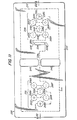
- Another embodiment of a transdermal drug applicator in accordance with the present invention, which is designated by the numeral 200, is illustrated in Figures 11 and 12.
Drug applicator 200 includes a pair of optionally replaceable drug reservoirs B and C, and a power source, such as twelvebutton batteries 202A-L, all enclosed by anouter cover 204, which is preferably aluminized.Button batteries 202A-L are arranged in twounits batteries 202A-E and 202F-L, respectively.Battery unit 206 is located proximately above reservoir B, which is negative in charge, andbattery unit 206 is located proximately above reservoir C, which is positive in charge.Batteries 202A-L can vary in number and voltage in accordance with a particular design for a particular drug or drugs contained in the reservoirs. Each battery illustrated is typically 1.5 volts, but the system can include more or fewer batteries each having a lesser or greater voltage. Alternatively, flat batteries typically approximately 1.5mm in thickness can be used in lieu of the button batteries.Button batteries 202A-L have vertically opposed terminals. The charges of the topside terminals ofbutton batteries 202A-L are shown in Figure 1. A flexibleplastic substrate 210, such as "Mylar" haselectroconductive coating 212, preferably an electroconductive graphite paint, applied to one side and anadhesive layer 214 applied to the opposite side.Substrate 210 is non-conductive, impermeable, stable, and compatible with drugs, adhesives, the skin, and materials from whichdrug applicator 200 is fabricated.Substrate 210 hasend portions conductive paint 212 being in electrical contact with the inner side of reservoirs B and C atend portions Conductive paint 212 covers two separate areas ofsubstrate 210 each in contact withend portions end portions Adhesive layer 214 adheres toadhesive layer 214 at theend portions Conductive paint 212, which covers the entire undersurface ofend portions substrate 210, follows the folded contour ofsubstrate 210 inwardly, or upwardly, so thatpaint 212 is on the top surface side of the main portion ofsubstrate 210 so thatpaint 212 is in electrical contact with the bottomside terminals ofbatteries 202A-L. At the areas ofbattery units 206 facingbottomside terminals 202A-L,paint 212 is configured as printedcircuits circuits batteries 202A-L atbattery units stiff plastic sheet 222, which extends over allbatteries 202A-L. Acurrent conditioner 224 is positionedproximate battery unit 208 is connected in series withbatteries 202A-L by a printedcircuit 226 on the undersurface ofplastic sheet 222. Electroconductive adhesive paste drops 228 are preferably used to ensure good electrical connections between the terminals of the batteries and printedcircuits current conditioner 224. An electrical circuit thus exists between reservoirs B and C through the skin upon placement ofapplicator 200 upon the skin and throughbatteries 202A-L andcurrent conditioner 224. - A pair of
perforated plastic liners batteries 202A-L primarily to inhibit any spreading ofdrops 228. Perforations in liners 230 provide access for drops 228. A spacer, such asfoam spacer 232, is preferably positioned between the pair ofliners sealable plastic liner 234 is positioned on the underside ofapplicator 200 and is connected to the periphery ofcover 204. Askin adhesive 236 is placed on the underside ofliner 234. A removable release liner (not shown) is ordinarily placed on the underside ofliner 234 and is removed prior to use of the applicator. Sealed edges in the form of sealedside walls 238 are disposed about the periphery of reservoirs B and C in order to prevent passage of the drug or drugs from the reservoirs. The sealedside walls 238 may be formed, if desired, by heat sealing throughliner 234 and through the drug reservoir material tosubstrate 210. Alternately,walls 238 can be formed by using a suitable material such as silicon adhesive to seal the peripheral reservoir edges to affixliner 234 to drug reservoirs B and C. -
Drug applicator 200 can be assembled in steps from the components described above. These components are illustrated in Figure 13 in an exploded perspective view of a drug applicator 242 analogous todrug applicator 200. - The assembly of applicator 242 comprises the following steps:
- a) positioning on a surface the bottom component, which is a
heat sealable liner 234 along with abottommost skin adhesive 236. A pair of reservoir windows 244B and 244C and cutouts 240A that are part of breathingwindows 240 are formed inliner 234; - b) placing drug reservoirs B and C over windows 244B and 244C;
- c) making one downward underfold of each
end portion substrate 210 so as to makesubstrate 210 with two layers at eachend portion Three button batteries 248A-C used for drug applicator 242 withbatteries 248A and 248B located inbattery unit 250 positioned on the left as viewed in Figure 13 and with battery 248C located inbattery unit 252 positioned on the right as viewed in Figure 13.Conductive paint 212 extends around the bottom sides of 216B and 216C to be in contact with the top sides of reservoirs B andC. Short indentations 254 and 256 ofconductive paint 212 extend onto the left and right topside ends, respectively, ofsubstrate 210 where batteries 246A and 246C are to be located. A printed circuit 258 of conductive paint, or ink, of the same material asconductive paint 212 extends between the areas of placement of batteries 248B and 248C in order to connect the terminals ofcurrent conditioner 224. A pair ofcutouts 240B that are part of breathingwindows 240 are formed in the center area ofsubstrate 210; - d) placing four electroconductive adhesive paste drops 228 on
indentations 254 and 256 and on the end portions of printed circuit 258; - e) placing
liner 230A uponsubstrate 210. Liner 210A has threeholes 262 for electroconductive drops 228 forbatteries 248A-C and ahole 264 for theelectroconductive drop 228 for one end ofcurrent conditioner 24 and a pair of cutouts 240C that are part ofbreathing windows 240. Nesting holes 262 and 264 are aligned with electroconductive paste drops 228; - f) placing
batteries 248A-C uponliner 230A overnesting holes 262 in electrical contact withdrops 228 forbatteries 248A and placingcurrent conditioner 224 uponliner 230A upon into electrical contact withdrop 228 at the end of printedcircuit 226; - g) placing a spacer, preferably a
foam space 232, ontoliner 230A.Foam spacer 232 forms threenesting holes 268 for receivingbatteries 248A-C, anesting hole 270 for receivingcurrent conditioner 224, and a pair of cutouts 240D that are part ofbreathing windows 240.Holes - h) placing electroconductive adhesive paste drops 274 onto the top side terminals of
batteries 248A-C; and placing electroconductive adhesive paste drops 274 into electrical contact with the top side terminals ofbatteries 248A-C; alternatively, in lieu of paste drops 274 an electroconductive paste can be coated onliner 210 and the paste can be die cut with the coating removed before the assembly process so as to isolate electroconductive paste units such as disks, which may be employed in the practice of the invention; - i) placing a
liner 230B overspacer 232.Liner 230B forms threeholes 278 forelectromagnetic drops 274 for the topside terminals ofbatteries 248A-C, ahole 280 for theelectromagnetic drop 274 forcurrent conditioner 224, and a pair ofcutouts 240E that are a part of breathingwindows 240; - j) placing a
plastic sheet 222 overliner 230B.Sheet 222 forms a pair ofcutouts 240E that are part ofbreathing windows 240. All cutouts 240A-240E are positioned in registry to form breathing holes 240. Printed circuits 286B and 286C are located on the underside ofliner 230B for connecting the terminals ofbatteries 248A and 248B and for connectingcurrent conditioner 224 with battery 248C, respectively; and - k) placing a cover 204 (as shown in Figure 12) over
plastic sheet 222 and over the entire assembled applicator 242 and attaching the edges ofcover 204 to the topside ofheat sealable liner 234. - Flat layered batteries such a
batteries button batteries 202A-L illustrated in Figures 11 and 12 and button batteries 248-C illustrated in Figure 13. In such a battery construction, the production method illustrated in Figure 10 can be used forapplicators 200 and 242. - Reservoirs B and C are enclosed at their sides by heat-sealed
walls 238. Either one or both reservoirs may be used, that is, a non-drug electrode may be substituted for either reservoir. A pair of breathingwindows 240 that extend transversely through the entire drug applicator 242 betweenbattery units - The two
battery units 206 and 207 in Figures 11 and 12 and the twobattery units - Figure 14 illustrates
transdermal drug applicator 300 having the same arrangement of elements as described fordug applicator 200 described earlier in relation to Figure 12 except for a flat,flexible substrate 302 made of plastic such as "Mylar" or other similar material.Substrate 210 is non-conductive, impermeable to the passage of liquid, stable, and compatible with drugs, adhesives, skin, and materials from whichdrug applicator 300 is fabricated.Substrate 302 has top andbottom electroconductive coatings substrate 302 in the vicinity of reservoir B and further has top and bottom electroconductive coatings 304B and 306B applied to the top and bottom surfaces, respectively, ofsubstrate 302 in the vicinity ofreservoir C. Coatings conductive coating 304A extends to electrical connection withbatteries batteries 202A-F. Likewise, top conductive coating 304B extends to electrical connection withbatteries batteries 202G-K. Bottom coating 306A is in electrical connection with reservoir B and bottom coating 306B is in electrical connection with reservoir C. - Figure 16 illustrates an enlarged detail view of
substrate 302 with top andbottom coatings electroconductive joining strips strip 308 includes a flexibletop substrate strip 312 made of the same material assubstrate 302 and an electroconductivetop coating strip 314 made of the same electroconductive material ascoatings Top coating strip 314 is in electrical connection with topconductive coating 304A. Similarly,bottom joining strip 310 includes a flexiblebottom substrate strip 316 made of the same material assubstrate 302 and an electroconductivebottom coating strip 318 made of the same electroconductive material ascoatings Bottom coating strip 318 is in electrical connection with bottomconductive coating 306A.Substrate 302 defines acircular hole 320A, which extends transversely throughsubstrate 302 and also through top and bottomconductive coatings bottom joining strips bottom coating strip bottom adhesives bottom joining strips hole 320A where their respective top and bottom coating strips 314 and 318 are joined in electrical contact at a juncture preferably held together by an electricallyconductive adhesive 326. - Top and
bottom joining strips hole 320A are the same for the electrical connection between top and bottom conductive coatings 304B and 306B athole 320B illustrated in Figure 14. - Figure 16 illustrates the assembly of the electrical connection between top and bottom coating strips 312 and 314. Top and bottom joining strips 304 and 306 are positioned spaced from top and bottom
conductive coatings substrate 302 prior to the next steps of pressuring top and bottom joining strips into mutual electrical contact inside ofhole 320A and into adhesive connection with top and bottomconductive coatings - Figures 17 and 18 illustrate another embodiment of a construction and arrangement for connecting top and bottom
conductive coatings mesh member 328 is positioned over a hole 327 extending throughsubstrate 302 and its topconductive coating 304A. Bottom conductive coating 306 extends across hole 327. Mesh member is pressed into adhesive contact with topconductive coating 304A aroundhole 320A and is further pressed intohole 320A into adhesive contact with bottomconductive coating 306A.Mesh member 328 has a plurality of mesh holes which are filled with aconductive material 330, such a carbon, which can be graphite, for example. Thus, top and bottomconductive coatings conductive material 330. Electrical connection of top and bottom conductive coatings 304B and 306B through hole 304B is of the same arrangement and construction described. - Figures 19 and 20 illustrate yet another embodiment of a construction and arrangement for connecting top and bottom
conductive coatings substrate 302 and topconductive coating 304A form a plurality of smalltransverse holes 332 over acylindrical volume 334.Holes 332 are filled with aconductive material 336, such as carbon, which can be graphite, which electrically connects top and bottomconductive coatings - Figures 219 and 22 illustrate yet another embodiment of a construction and arrangement for connecting top and bottom
conductive coatings substrate 302 and topconductive coating 304A form a plurality of small transversetransverse slots 338 over a cylindrical volume 340, withslots 338 being of different lateral dimensions so as to stay within the dimensions of volume 340.Slots 338 are filled with aconductive material 342, such as carbon, which can be graphite, which electrically connects top and bottomconductive coatings - Although the present invention has been described in some detail by way of illustration and example for purposes of clarity and understanding, it will, of course, be understood that various changes and modifications may be made in the form, details, and arrangements of the parts without departing from the scope of the invention as set forth in the following claims.
Claims (46)
a flexible, non-conductive substrate (30) having a plurality of conductive coated areas, said conductive coated areas including drug reservoir electrodes, said flexible substrate (30) and said conductive coated areas forming a single, substantially flat, flexible member,
a plurality of separate drug reservoirs (26,28) in electrical contact with said drug reservoir electrodes,
at least one battery (20) connected in series with said drug reservoir electrodes,
electrical current conditioning means (22,84) in series with said battery (20) and said drug reservoir electrodes, and a conformal covering for said drug applicator.
Applications Claiming Priority (4)
| Application Number | Priority Date | Filing Date | Title |
|---|---|---|---|
| US07/058,527 US4883457A (en) | 1983-08-18 | 1987-06-05 | Disposable and/or replenishable transdermal drug applicators and methods of manufacturing same |
| US58527 | 1987-06-05 | ||
| US169385 | 1988-03-17 | ||
| US07/169,385 US4865582A (en) | 1987-06-05 | 1988-03-17 | Disposable transdermal drug applicators |
Publications (3)
| Publication Number | Publication Date |
|---|---|
| EP0293893A2 true EP0293893A2 (en) | 1988-12-07 |
| EP0293893A3 EP0293893A3 (en) | 1989-03-22 |
| EP0293893B1 EP0293893B1 (en) | 1999-02-24 |
Family
ID=26737714
Family Applications (1)
| Application Number | Title | Priority Date | Filing Date |
|---|---|---|---|
| EP88108838A Expired - Lifetime EP0293893B1 (en) | 1987-06-05 | 1988-06-02 | A method of manufactoring a transdermal drug applicator |
Country Status (10)
| Country | Link |
|---|---|
| US (1) | US4865582A (en) |
| EP (1) | EP0293893B1 (en) |
| JP (2) | JP2632367B2 (en) |
| AR (1) | AR246025A1 (en) |
| AT (1) | ATE176873T1 (en) |
| AU (1) | AU618734B2 (en) |
| BR (1) | BR8802677A (en) |
| CA (1) | CA1322921C (en) |
| DE (1) | DE3856306T2 (en) |
| ES (1) | ES2131039T3 (en) |
Cited By (14)
| Publication number | Priority date | Publication date | Assignee | Title |
|---|---|---|---|---|
| EP0468430A2 (en) * | 1990-07-27 | 1992-01-29 | Becton, Dickinson and Company | Electrically assisted transdermal transport device and method for renewing the device |
| US5125894A (en) * | 1990-03-30 | 1992-06-30 | Alza Corporation | Method and apparatus for controlled environment electrotransport |
| WO1993024178A1 (en) * | 1992-06-02 | 1993-12-09 | Alza Corporation | Iontophoretic drug delivery apparatus |
| US5279543A (en) * | 1988-01-29 | 1994-01-18 | The Regents Of The University Of California | Device for iontophoretic non-invasive sampling or delivery of substances |
| US5362307A (en) * | 1989-01-24 | 1994-11-08 | The Regents Of The University Of California | Method for the iontophoretic non-invasive-determination of the in vivo concentration level of an inorganic or organic substance |
| WO1994027671A1 (en) * | 1993-05-28 | 1994-12-08 | Alza Corporation | Electrotransport agent delivery device |
| WO1996017650A1 (en) * | 1993-12-02 | 1996-06-13 | Alza Corporation | Electrotransport delivery device and method of making same |
| AU670390B2 (en) * | 1993-09-10 | 1996-07-11 | Asulab S.A. | Three part device for the transdermic administration of drugs by electrophoresis or iontophoresis |
| WO1996022124A1 (en) * | 1995-01-18 | 1996-07-25 | Alza Corporation | Electrotransport device having reusable controller power saver |
| WO1998029158A1 (en) * | 1996-12-26 | 1998-07-09 | Elan International Services Limited | Improved electrode and iontophoretic device and method |
| US6004309A (en) * | 1990-03-30 | 1999-12-21 | Alza Corporation | Method and apparatus for controlled environment electrotransport |
| US6078842A (en) * | 1997-04-08 | 2000-06-20 | Elan Corporation, Plc | Electrode and iontophoretic device and method |
| US6694183B1 (en) | 1999-06-21 | 2004-02-17 | Eeva-Liisa Lehtoluoto | Skin cleansing device |
| EP3231363A4 (en) * | 2014-12-08 | 2018-07-11 | Prokidai Co., Ltd. | Bioelectrode |
Families Citing this family (51)
| Publication number | Priority date | Publication date | Assignee | Title |
|---|---|---|---|---|
| US5605536A (en) * | 1983-08-18 | 1997-02-25 | Drug Delivery Systems Inc. | Transdermal drug applicator and electrodes therefor |
| US5651768A (en) * | 1983-08-18 | 1997-07-29 | Drug Delivery Systems, Inc. | Transdermal drug applicator and electrodes therefor |
| US5135477A (en) * | 1984-10-29 | 1992-08-04 | Medtronic, Inc. | Iontophoretic drug delivery |
| US6956032B1 (en) | 1986-04-18 | 2005-10-18 | Carnegie Mellon University | Cyanine dyes as labeling reagents for detection of biological and other materials by luminescence methods |
| US5746711A (en) * | 1987-01-05 | 1998-05-05 | Drug Delivery Systems, Inc. | Programmable control and mounting system for transdermal drug applicator |
| IL86076A (en) * | 1988-04-14 | 1992-12-01 | Inventor S Funding Corp Ltd | Transdermal drug delivery device |
| US4950229A (en) * | 1989-09-25 | 1990-08-21 | Becton, Dickinson And Company | Apparatus for an electrode used for iontophoresis |
| US5207752A (en) * | 1990-03-30 | 1993-05-04 | Alza Corporation | Iontophoretic drug delivery system with two-stage delivery profile |
| DK0522043T3 (en) * | 1990-03-30 | 2004-02-23 | Alza Corp | Iontophoretic administration device |
| US5087241A (en) * | 1990-07-24 | 1992-02-11 | Empi, Inc. | Iontophoresis electrode with reservoir and injection site |
| EP0751801B1 (en) * | 1992-06-02 | 1997-11-26 | Alza Corporation | Electrotransport drug delivery device |
| US5312326A (en) * | 1992-06-02 | 1994-05-17 | Alza Corporation | Iontophoretic drug delivery apparatus |
| US5380272A (en) * | 1993-01-28 | 1995-01-10 | Scientific Innovations Ltd. | Transcutaneous drug delivery applicator |
| US5415629A (en) * | 1993-09-15 | 1995-05-16 | Henley; Julian L. | Programmable apparatus for the transdermal delivery of drugs and method |
| WO1996010442A1 (en) * | 1994-09-30 | 1996-04-11 | Becton Dickinson And Company | Improved iontophoretic drug delivery device |
| US5498235A (en) * | 1994-09-30 | 1996-03-12 | Becton Dickinson And Company | Iontophoresis assembly including patch/controller attachment |
| US5954685A (en) * | 1996-05-24 | 1999-09-21 | Cygnus, Inc. | Electrochemical sensor with dual purpose electrode |
| WO1997048444A1 (en) * | 1996-06-19 | 1997-12-24 | Becton Dickinson And Company | Iontophoretic delivery of cell adhesion inhibitors |
| US5991655A (en) * | 1997-03-03 | 1999-11-23 | Drug Delivery Systems, Inc. | Iontophoretic drug delivery device and method of manufacturing the same |
| JPH11239621A (en) * | 1998-02-25 | 1999-09-07 | Hisamitsu Pharmaceut Co Inc | Iontophoresis device |
| US6148231A (en) | 1998-09-15 | 2000-11-14 | Biophoretic Therapeutic Systems, Llc | Iontophoretic drug delivery electrodes and method |
| US6792306B2 (en) | 2000-03-10 | 2004-09-14 | Biophoretic Therapeutic Systems, Llc | Finger-mounted electrokinetic delivery system for self-administration of medicaments and methods therefor |
| US6477410B1 (en) | 2000-05-31 | 2002-11-05 | Biophoretic Therapeutic Systems, Llc | Electrokinetic delivery of medicaments |
| US7127285B2 (en) | 1999-03-12 | 2006-10-24 | Transport Pharmaceuticals Inc. | Systems and methods for electrokinetic delivery of a substance |
| AT411150B (en) * | 2001-05-25 | 2003-10-27 | Nova Technical Res Gmbh | DEVICE FOR INTRODUCING SUBSTANCES |
| NZ532402A (en) * | 2001-10-31 | 2005-11-25 | Transcutaneous Tech Inc | Iontophoresis device |
| US7220778B2 (en) * | 2003-04-15 | 2007-05-22 | The General Hospital Corporation | Methods and devices for epithelial protection during photodynamic therapy |
| WO2006083876A2 (en) | 2005-02-01 | 2006-08-10 | Intelliject, Llc | Devices, systems, and methods for medicament delivery |
| US8206360B2 (en) | 2005-02-01 | 2012-06-26 | Intelliject, Inc. | Devices, systems and methods for medicament delivery |
| US9022980B2 (en) | 2005-02-01 | 2015-05-05 | Kaleo, Inc. | Medical injector simulation device |
| US8361026B2 (en) | 2005-02-01 | 2013-01-29 | Intelliject, Inc. | Apparatus and methods for self-administration of vaccines and other medicaments |
| US7731686B2 (en) * | 2005-02-01 | 2010-06-08 | Intelliject, Inc. | Devices, systems and methods for medicament delivery |
| US8231573B2 (en) | 2005-02-01 | 2012-07-31 | Intelliject, Inc. | Medicament delivery device having an electronic circuit system |
| US20070093787A1 (en) * | 2005-09-30 | 2007-04-26 | Transcutaneous Technologies Inc. | Iontophoresis device to deliver multiple active agents to biological interfaces |
| AU2007238685B2 (en) * | 2006-04-13 | 2012-09-13 | Teva Pharmaceuticals International Gmbh | Transdermal methods and systems for the delivery of anti-migraine compounds |
| WO2008091838A2 (en) | 2007-01-22 | 2008-07-31 | Intelliject, Inc. | Medical injector with compliance tracking and monitoring |
| US8197844B2 (en) | 2007-06-08 | 2012-06-12 | Activatek, Inc. | Active electrode for transdermal medicament administration |
| US20080312579A1 (en) * | 2007-06-15 | 2008-12-18 | Transport Pharmaceuticals, Inc. | Method and system for mitigating current concentration in electrokinetic drug delivery |
| WO2009003173A1 (en) * | 2007-06-27 | 2008-12-31 | The General Hospital Corporation | Method and apparatus for optical inhibition of photodymanic therapy |
| SG183726A1 (en) | 2007-08-14 | 2012-09-27 | Hutchinson Fred Cancer Res | Needle array assembly and method for delivering therapeutic agents |
| US20110160640A1 (en) * | 2008-01-18 | 2011-06-30 | Yanaki Jamal S | Operation management of active transdermal medicament patch |
| US8862223B2 (en) * | 2008-01-18 | 2014-10-14 | Activatek, Inc. | Active transdermal medicament patch and circuit board for same |
| USD994111S1 (en) | 2008-05-12 | 2023-08-01 | Kaleo, Inc. | Medicament delivery device cover |
| WO2013059706A1 (en) * | 2011-10-19 | 2013-04-25 | Neuro Resouce Group, Inc. | Electrode apparatus and method of manufacturing electrodes |
| JP2014534864A (en) | 2011-10-28 | 2014-12-25 | プレサージュ バイオサイエンシズ,インコーポレイテッド | Drug delivery method |
| EP2938376A4 (en) | 2012-12-27 | 2017-01-25 | Kaleo, Inc. | Devices, systems and methods for locating and interacting with medicament delivery systems |
| WO2015187377A1 (en) * | 2014-06-02 | 2015-12-10 | Avery Dennison Corporation | Sensor patches |
| FR3034017B1 (en) * | 2015-03-24 | 2018-11-02 | Feeligreen | ADHESIVE POLYMERIC MATRIX FOR IONTOPHORESIS AND DEVICE FOR IONTOPHORESIS COMPRISING SAID MATRIX |
| AU2018210313A1 (en) | 2017-01-17 | 2019-06-20 | Kaleo, Inc. | Medicament delivery devices with wireless connectivity and event detection |
| CN110548219A (en) * | 2018-06-01 | 2019-12-10 | 安徽舒源妇幼用品有限公司 | adult nursing pad and processing method thereof |
| WO2020018433A1 (en) | 2018-07-16 | 2020-01-23 | Kaleo, Inc. | Medicament delivery devices with wireless connectivity and compliance detection |
Citations (4)
| Publication number | Priority date | Publication date | Assignee | Title |
|---|---|---|---|---|
| FR2263792A1 (en) * | 1974-03-12 | 1975-10-10 | Bondivenne Jean | Ionotherapy current generator - comprises thin flexible bag giving percutaneous medicament penetration |
| EP0147524A1 (en) * | 1983-08-18 | 1985-07-10 | Drug Delivery Systems Inc. | Applicator for the non-invasive transcutaneous delivery of medicament |
| WO1986007269A1 (en) * | 1985-06-10 | 1986-12-18 | Drug Delivery Systems Inc. | Programmable control and mounting system for transdermal drug applicator |
| EP0225556A2 (en) * | 1985-12-10 | 1987-06-16 | Drug Delivery Systems Inc. | Disposable and/or replenishable transdermal drug applicators and methods of manufacturing same |
Family Cites Families (10)
| Publication number | Priority date | Publication date | Assignee | Title |
|---|---|---|---|---|
| US169385A (en) * | 1875-11-02 | Improvement in roofing compositions | ||
| CA1111503A (en) * | 1977-04-02 | 1981-10-27 | Isoji Sakurada | Biomedical electrode |
| US4325367A (en) * | 1977-06-13 | 1982-04-20 | Robert Tapper | Iontophoretic treatment apparatus |
| US4267840A (en) * | 1979-01-08 | 1981-05-19 | Johnson & Johnson | Electrosurgical grounding pad |
| JPS5810066A (en) * | 1981-07-10 | 1983-01-20 | 株式会社アドバンス | Plaster structure for ion tofuorese |
| EP0092015A1 (en) * | 1982-04-16 | 1983-10-26 | Roland Brodard | Ionizing device |
| US4622031A (en) * | 1983-08-18 | 1986-11-11 | Drug Delivery Systems Inc. | Indicator for electrophoretic transcutaneous drug delivery device |
| JPH0239267B2 (en) * | 1984-06-12 | 1990-09-04 | Intaa Noba Kk | INIONCHUNYUSHIKICHIRYOSOCHI |
| US4725263A (en) * | 1986-07-31 | 1988-02-16 | Medtronic, Inc. | Programmable constant current source transdermal drug delivery system |
| JP3018604B2 (en) * | 1991-07-12 | 2000-03-13 | 松下電器産業株式会社 | Spot killer circuit |
-
1988
- 1988-03-17 US US07/169,385 patent/US4865582A/en not_active Expired - Lifetime
- 1988-05-24 AU AU16550/88A patent/AU618734B2/en not_active Ceased
- 1988-06-02 AR AR88311018A patent/AR246025A1/en active
- 1988-06-02 AT AT88108838T patent/ATE176873T1/en active
- 1988-06-02 EP EP88108838A patent/EP0293893B1/en not_active Expired - Lifetime
- 1988-06-02 BR BR8802677A patent/BR8802677A/en not_active IP Right Cessation
- 1988-06-02 DE DE3856306T patent/DE3856306T2/en not_active Expired - Fee Related
- 1988-06-02 ES ES88108838T patent/ES2131039T3/en not_active Expired - Lifetime
- 1988-06-03 JP JP63137197A patent/JP2632367B2/en not_active Expired - Lifetime
- 1988-06-06 CA CA000568748A patent/CA1322921C/en not_active Expired - Fee Related
-
1995
- 1995-11-16 JP JP7322340A patent/JPH08238325A/en active Pending
Patent Citations (4)
| Publication number | Priority date | Publication date | Assignee | Title |
|---|---|---|---|---|
| FR2263792A1 (en) * | 1974-03-12 | 1975-10-10 | Bondivenne Jean | Ionotherapy current generator - comprises thin flexible bag giving percutaneous medicament penetration |
| EP0147524A1 (en) * | 1983-08-18 | 1985-07-10 | Drug Delivery Systems Inc. | Applicator for the non-invasive transcutaneous delivery of medicament |
| WO1986007269A1 (en) * | 1985-06-10 | 1986-12-18 | Drug Delivery Systems Inc. | Programmable control and mounting system for transdermal drug applicator |
| EP0225556A2 (en) * | 1985-12-10 | 1987-06-16 | Drug Delivery Systems Inc. | Disposable and/or replenishable transdermal drug applicators and methods of manufacturing same |
Cited By (23)
| Publication number | Priority date | Publication date | Assignee | Title |
|---|---|---|---|---|
| US6714815B2 (en) | 1988-01-29 | 2004-03-30 | The Regents Of The University Of California | Method for the iontophoretic non-invasive determination of the in vivo concentration level of an inorganic or organic substance |
| US6542765B1 (en) | 1988-01-29 | 2003-04-01 | The Regent Of The University Of California | Method for the iontophoretic non-invasive determination of the in vivo concentration level of an inorganic or organic substance |
| US5730714A (en) * | 1988-01-29 | 1998-03-24 | The Regents Of The University Of California | Method for the iontophoretic non-invasive determination of the in vivo concentration level of glucose |
| US5279543A (en) * | 1988-01-29 | 1994-01-18 | The Regents Of The University Of California | Device for iontophoretic non-invasive sampling or delivery of substances |
| US5362307A (en) * | 1989-01-24 | 1994-11-08 | The Regents Of The University Of California | Method for the iontophoretic non-invasive-determination of the in vivo concentration level of an inorganic or organic substance |
| US6004309A (en) * | 1990-03-30 | 1999-12-21 | Alza Corporation | Method and apparatus for controlled environment electrotransport |
| US6289241B1 (en) | 1990-03-30 | 2001-09-11 | Alza Corporation | Method and apparatus for controlled environment electrotransport |
| US5443442A (en) * | 1990-03-30 | 1995-08-22 | Alza Corporation | Method and apparatus for controlled environment electrotransport |
| US5591124A (en) * | 1990-03-30 | 1997-01-07 | Alza Corporation | Method and apparatus for controlled environment electrotransport |
| US5622530A (en) * | 1990-03-30 | 1997-04-22 | Alza Corporation | Method and apparatus for controlled environment electrotransport |
| US5125894A (en) * | 1990-03-30 | 1992-06-30 | Alza Corporation | Method and apparatus for controlled environment electrotransport |
| EP0468430A3 (en) * | 1990-07-27 | 1992-03-25 | Becton Dickinson And Company | Electrically assisted transdermal transport device and method for renewing the device |
| EP0468430A2 (en) * | 1990-07-27 | 1992-01-29 | Becton, Dickinson and Company | Electrically assisted transdermal transport device and method for renewing the device |
| WO1993024178A1 (en) * | 1992-06-02 | 1993-12-09 | Alza Corporation | Iontophoretic drug delivery apparatus |
| WO1994027671A1 (en) * | 1993-05-28 | 1994-12-08 | Alza Corporation | Electrotransport agent delivery device |
| AU670390B2 (en) * | 1993-09-10 | 1996-07-11 | Asulab S.A. | Three part device for the transdermic administration of drugs by electrophoresis or iontophoresis |
| WO1996017650A1 (en) * | 1993-12-02 | 1996-06-13 | Alza Corporation | Electrotransport delivery device and method of making same |
| WO1996022124A1 (en) * | 1995-01-18 | 1996-07-25 | Alza Corporation | Electrotransport device having reusable controller power saver |
| WO1998029158A1 (en) * | 1996-12-26 | 1998-07-09 | Elan International Services Limited | Improved electrode and iontophoretic device and method |
| US6078842A (en) * | 1997-04-08 | 2000-06-20 | Elan Corporation, Plc | Electrode and iontophoretic device and method |
| US6694183B1 (en) | 1999-06-21 | 2004-02-17 | Eeva-Liisa Lehtoluoto | Skin cleansing device |
| EP3231363A4 (en) * | 2014-12-08 | 2018-07-11 | Prokidai Co., Ltd. | Bioelectrode |
| US10765335B2 (en) | 2014-12-08 | 2020-09-08 | Prokidai Co., Ltd. | Biomedical electrode |
Also Published As
| Publication number | Publication date |
|---|---|
| BR8802677A (en) | 1988-12-27 |
| AR246025A1 (en) | 1994-03-30 |
| ATE176873T1 (en) | 1999-03-15 |
| AU1655088A (en) | 1988-12-08 |
| AU618734B2 (en) | 1992-01-09 |
| JPS63317162A (en) | 1988-12-26 |
| CA1322921C (en) | 1993-10-12 |
| US4865582A (en) | 1989-09-12 |
| DE3856306T2 (en) | 1999-09-30 |
| DE3856306D1 (en) | 1999-04-01 |
| JPH08238325A (en) | 1996-09-17 |
| ES2131039T3 (en) | 1999-07-16 |
| EP0293893A3 (en) | 1989-03-22 |
| EP0293893B1 (en) | 1999-02-24 |
| JP2632367B2 (en) | 1997-07-23 |
Similar Documents
| Publication | Publication Date | Title |
|---|---|---|
| EP0293893B1 (en) | A method of manufactoring a transdermal drug applicator | |
| US4883457A (en) | Disposable and/or replenishable transdermal drug applicators and methods of manufacturing same | |
| EP0225556B1 (en) | Disposable and/or replenishable transdermal drug applicators and methods of manufacturing same | |
| US5976101A (en) | Disposable and/or replenishable transdermal drug applicators and methods of manufacturing same | |
| US5167617A (en) | Disposable electralytic transdermal drug applicator | |
| US5991655A (en) | Iontophoretic drug delivery device and method of manufacturing the same | |
| CA1224993A (en) | Applicator for the non-invasive transcutaneous delivery of medicament | |
| AU670390B2 (en) | Three part device for the transdermic administration of drugs by electrophoresis or iontophoresis | |
| CA2202898C (en) | Electrotransport delivery device and method of making same | |
| EP1986547B1 (en) | Biomedical surface electrode | |
| US5562607A (en) | Electrotransport device having reusable controller power saver | |
| US5879322A (en) | Self-contained transdermal drug delivery device | |
| EP0240593B1 (en) | Improved transdermal drug applicator and electrodes therefor | |
| AU721419B2 (en) | Iontophoresis device structure | |
| CA2570793C (en) | Packaging for medical pads and electrodes | |
| KR960011033B1 (en) | Disposable and/or replenishable transdermal drug applicators and method of manufacturing the same |
Legal Events
| Date | Code | Title | Description |
|---|---|---|---|
| PUAI | Public reference made under article 153(3) epc to a published international application that has entered the european phase |
Free format text: ORIGINAL CODE: 0009012 |
|
| AK | Designated contracting states |
Kind code of ref document: A2 Designated state(s): AT BE CH DE ES FR GB GR IT LI LU NL SE |
|
| PUAL | Search report despatched |
Free format text: ORIGINAL CODE: 0009013 |
|
| AK | Designated contracting states |
Kind code of ref document: A3 Designated state(s): AT BE CH DE ES FR GB GR IT LI LU NL SE |
|
| 17P | Request for examination filed |
Effective date: 19890825 |
|
| 17Q | First examination report despatched |
Effective date: 19920312 |
|
| GRAG | Despatch of communication of intention to grant |
Free format text: ORIGINAL CODE: EPIDOS AGRA |
|
| GRAG | Despatch of communication of intention to grant |
Free format text: ORIGINAL CODE: EPIDOS AGRA |
|
| GRAH | Despatch of communication of intention to grant a patent |
Free format text: ORIGINAL CODE: EPIDOS IGRA |
|
| GRAH | Despatch of communication of intention to grant a patent |
Free format text: ORIGINAL CODE: EPIDOS IGRA |
|
| GRAA | (expected) grant |
Free format text: ORIGINAL CODE: 0009210 |
|
| AK | Designated contracting states |
Kind code of ref document: B1 Designated state(s): AT BE CH DE ES FR GB GR IT LI LU NL SE |
|
| PG25 | Lapsed in a contracting state [announced via postgrant information from national office to epo] |
Ref country code: NL Free format text: LAPSE BECAUSE OF FAILURE TO SUBMIT A TRANSLATION OF THE DESCRIPTION OR TO PAY THE FEE WITHIN THE PRESCRIBED TIME-LIMIT Effective date: 19990224 Ref country code: LI Free format text: LAPSE BECAUSE OF FAILURE TO SUBMIT A TRANSLATION OF THE DESCRIPTION OR TO PAY THE FEE WITHIN THE PRESCRIBED TIME-LIMIT Effective date: 19990224 Ref country code: GR Free format text: LAPSE BECAUSE OF NON-PAYMENT OF DUE FEES Effective date: 19990224 Ref country code: CH Free format text: LAPSE BECAUSE OF FAILURE TO SUBMIT A TRANSLATION OF THE DESCRIPTION OR TO PAY THE FEE WITHIN THE PRESCRIBED TIME-LIMIT Effective date: 19990224 Ref country code: BE Free format text: LAPSE BECAUSE OF FAILURE TO SUBMIT A TRANSLATION OF THE DESCRIPTION OR TO PAY THE FEE WITHIN THE PRESCRIBED TIME-LIMIT Effective date: 19990224 Ref country code: AT Free format text: LAPSE BECAUSE OF FAILURE TO SUBMIT A TRANSLATION OF THE DESCRIPTION OR TO PAY THE FEE WITHIN THE PRESCRIBED TIME-LIMIT Effective date: 19990224 |
|
| REF | Corresponds to: |
Ref document number: 176873 Country of ref document: AT Date of ref document: 19990315 Kind code of ref document: T |
|
| REG | Reference to a national code |
Ref country code: CH Ref legal event code: EP |
|
| REF | Corresponds to: |
Ref document number: 3856306 Country of ref document: DE Date of ref document: 19990401 |
|
| ET | Fr: translation filed | ||
| PG25 | Lapsed in a contracting state [announced via postgrant information from national office to epo] |
Ref country code: LU Free format text: LAPSE BECAUSE OF NON-PAYMENT OF DUE FEES Effective date: 19990602 |
|
| REG | Reference to a national code |
Ref country code: ES Ref legal event code: FG2A Ref document number: 2131039 Country of ref document: ES Kind code of ref document: T3 |
|
| NLV1 | Nl: lapsed or annulled due to failure to fulfill the requirements of art. 29p and 29m of the patents act | ||
| REG | Reference to a national code |
Ref country code: CH Ref legal event code: PL |
|
| PLBE | No opposition filed within time limit |
Free format text: ORIGINAL CODE: 0009261 |
|
| STAA | Information on the status of an ep patent application or granted ep patent |
Free format text: STATUS: NO OPPOSITION FILED WITHIN TIME LIMIT |
|
| 26N | No opposition filed | ||
| PGFP | Annual fee paid to national office [announced via postgrant information from national office to epo] |
Ref country code: SE Payment date: 20010405 Year of fee payment: 14 |
|
| PGFP | Annual fee paid to national office [announced via postgrant information from national office to epo] |
Ref country code: ES Payment date: 20010613 Year of fee payment: 14 |
|
| REG | Reference to a national code |
Ref country code: GB Ref legal event code: IF02 |
|
| PG25 | Lapsed in a contracting state [announced via postgrant information from national office to epo] |
Ref country code: SE Free format text: LAPSE BECAUSE OF NON-PAYMENT OF DUE FEES Effective date: 20020603 Ref country code: ES Free format text: LAPSE BECAUSE OF NON-PAYMENT OF DUE FEES Effective date: 20020603 |
|
| EUG | Se: european patent has lapsed | ||
| PGFP | Annual fee paid to national office [announced via postgrant information from national office to epo] |
Ref country code: GB Payment date: 20030501 Year of fee payment: 16 |
|
| REG | Reference to a national code |
Ref country code: ES Ref legal event code: FD2A Effective date: 20030711 |
|
| PG25 | Lapsed in a contracting state [announced via postgrant information from national office to epo] |
Ref country code: GB Free format text: LAPSE BECAUSE OF NON-PAYMENT OF DUE FEES Effective date: 20040602 |
|
| PGFP | Annual fee paid to national office [announced via postgrant information from national office to epo] |
Ref country code: FR Payment date: 20040608 Year of fee payment: 17 |
|
| PGFP | Annual fee paid to national office [announced via postgrant information from national office to epo] |
Ref country code: DE Payment date: 20040610 Year of fee payment: 17 |
|
| GBPC | Gb: european patent ceased through non-payment of renewal fee | ||
| PG25 | Lapsed in a contracting state [announced via postgrant information from national office to epo] |
Ref country code: IT Free format text: LAPSE BECAUSE OF NON-PAYMENT OF DUE FEES Effective date: 20050602 |
|
| PG25 | Lapsed in a contracting state [announced via postgrant information from national office to epo] |
Ref country code: DE Free format text: LAPSE BECAUSE OF NON-PAYMENT OF DUE FEES Effective date: 20060103 |
|
| PG25 | Lapsed in a contracting state [announced via postgrant information from national office to epo] |
Ref country code: FR Free format text: LAPSE BECAUSE OF NON-PAYMENT OF DUE FEES Effective date: 20060228 |
|
| REG | Reference to a national code |
Ref country code: FR Ref legal event code: ST Effective date: 20060228 |