EP0294191A2 - Reception control apparatus for a television receiver - Google Patents
Reception control apparatus for a television receiver Download PDFInfo
- Publication number
- EP0294191A2 EP0294191A2 EP88305025A EP88305025A EP0294191A2 EP 0294191 A2 EP0294191 A2 EP 0294191A2 EP 88305025 A EP88305025 A EP 88305025A EP 88305025 A EP88305025 A EP 88305025A EP 0294191 A2 EP0294191 A2 EP 0294191A2
- Authority
- EP
- European Patent Office
- Prior art keywords
- reception control
- data
- control data
- reception
- channel selection
- Prior art date
- Legal status (The legal status is an assumption and is not a legal conclusion. Google has not performed a legal analysis and makes no representation as to the accuracy of the status listed.)
- Granted
Links
- 230000004913 activation Effects 0.000 claims 1
- 238000004364 calculation method Methods 0.000 description 11
- 230000004044 response Effects 0.000 description 8
- 238000013500 data storage Methods 0.000 description 5
- 238000010586 diagram Methods 0.000 description 4
- 238000012986 modification Methods 0.000 description 2
- 230000004048 modification Effects 0.000 description 2
- 238000010276 construction Methods 0.000 description 1
- 230000003247 decreasing effect Effects 0.000 description 1
Images


Classifications
-
- H—ELECTRICITY
- H04—ELECTRIC COMMUNICATION TECHNIQUE
- H04N—PICTORIAL COMMUNICATION, e.g. TELEVISION
- H04N5/00—Details of television systems
- H04N5/44—Receiver circuitry for the reception of television signals according to analogue transmission standards
-
- H—ELECTRICITY
- H04—ELECTRIC COMMUNICATION TECHNIQUE
- H04N—PICTORIAL COMMUNICATION, e.g. TELEVISION
- H04N21/00—Selective content distribution, e.g. interactive television or video on demand [VOD]
- H04N21/40—Client devices specifically adapted for the reception of or interaction with content, e.g. set-top-box [STB]; Operations thereof
- H04N21/43—Processing of content or additional data, e.g. demultiplexing additional data from a digital video stream; Elementary client operations, e.g. monitoring of home network or synchronising decoder's clock; Client middleware
- H04N21/438—Interfacing the downstream path of the transmission network originating from a server, e.g. retrieving MPEG packets from an IP network
- H04N21/4383—Accessing a communication channel
-
- H—ELECTRICITY
- H04—ELECTRIC COMMUNICATION TECHNIQUE
- H04N—PICTORIAL COMMUNICATION, e.g. TELEVISION
- H04N21/00—Selective content distribution, e.g. interactive television or video on demand [VOD]
- H04N21/40—Client devices specifically adapted for the reception of or interaction with content, e.g. set-top-box [STB]; Operations thereof
- H04N21/43—Processing of content or additional data, e.g. demultiplexing additional data from a digital video stream; Elementary client operations, e.g. monitoring of home network or synchronising decoder's clock; Client middleware
- H04N21/443—OS processes, e.g. booting an STB, implementing a Java virtual machine in an STB or power management in an STB
- H04N21/4436—Power management, e.g. shutting down unused components of the receiver
-
- H—ELECTRICITY
- H04—ELECTRIC COMMUNICATION TECHNIQUE
- H04N—PICTORIAL COMMUNICATION, e.g. TELEVISION
- H04N21/00—Selective content distribution, e.g. interactive television or video on demand [VOD]
- H04N21/40—Client devices specifically adapted for the reception of or interaction with content, e.g. set-top-box [STB]; Operations thereof
- H04N21/45—Management operations performed by the client for facilitating the reception of or the interaction with the content or administrating data related to the end-user or to the client device itself, e.g. learning user preferences for recommending movies, resolving scheduling conflicts
- H04N21/4508—Management of client data or end-user data
- H04N21/4532—Management of client data or end-user data involving end-user characteristics, e.g. viewer profile, preferences
-
- H—ELECTRICITY
- H04—ELECTRIC COMMUNICATION TECHNIQUE
- H04N—PICTORIAL COMMUNICATION, e.g. TELEVISION
- H04N21/00—Selective content distribution, e.g. interactive television or video on demand [VOD]
- H04N21/40—Client devices specifically adapted for the reception of or interaction with content, e.g. set-top-box [STB]; Operations thereof
- H04N21/45—Management operations performed by the client for facilitating the reception of or the interaction with the content or administrating data related to the end-user or to the client device itself, e.g. learning user preferences for recommending movies, resolving scheduling conflicts
- H04N21/466—Learning process for intelligent management, e.g. learning user preferences for recommending movies
Definitions
- the present invention relates generally to a reception control apparatus used for a television receiver, and more particularly, to a reception control apparatus used for a television receiver, in which a reception control, e.g., a reception channel selection for a television receiver is automatically performed.
- a reception control e.g., a reception channel selection for a television receiver is automatically performed.
- TV receivers digital controls for a reception channel selection and a sound volume control are very popular.
- Such a TV receiver has a keyboard for manual controls of the TV receiver, a microcomputer for performing digital controls of the TV receiver, a memory storing a variety of control data and a tuner.
- the keyboard is mounted on a front panel or a remote controller of the TV receiver.
- the microcomputer reads out a suitable operation data, e.g., a tuning voltage data from the memory in response to an operation of the keyboard.
- the memory is generally comprised of a read only memory (referred as ROM hereafter).
- the operation data e.g., the tuning voltage data read out from the ROM are converted to an analog tuning voltage by a conventional digital to analog converter (referred as D/A converter hereafter) and the analog tuning voltage is applied to the tuner.
- the tuner is generally comprised of a voltage synthesizer tuning circuit.
- the tuning voltage is applied to a variable capacitance diode in a resonant circuit of the tuner.
- the tuner performs a prescribed tuning for a desired TV reception channel designated by the keyboard.
- the second memory is comprised of a random access memory (referred as RAM hereafter) which temporarily stores an operation data read out from the ROM upon operation of the keyboard or every predetermined time during the operation of the TV receiver.
- RAM random access memory
- the operation data stored in the RAM are held even after a power shut-off of the TV receiver.
- the RAM is always activated by a suitable auxiliary power supply source like a battery.
- a suitable auxiliary power supply source like a battery.
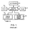
- FIGURE 1 is a block diagram illustrating the conventional reception control apparatus.
- a keyboard 11 is coupled to a system controller 12.
- the keyboard 11 is conventionally equipped with a power controller, a channel controller and a volume controller, but they are not shown in the drawing.
- the power controller controls the turn-on or the shut-off of a main power supply source of the TV receiver.
- the channel controller controls the selection of the TV reception channels.
- the volume controller controls the loudness of sound from the TV receiver.
- the channel controller has at least two types.
- One type of the channel controller has a prescribed number of channel keys associated to the TV reception channels, i.e., Ch-1, Ch-2, ..., Ch-12, Ch-U, respectively.
- Another type of the channel controller has two keys, one for raising the count of the channel numbers and another for lowering the count of the channel numbers.
- the volume controller has two keys for increasing and decreasing sound volume.
- the keyboard 11 When any key on the keyboard 11 is operated by a user, the keyboard 11 outputs a reception control data D1 associated to the operated key.
- the system controller 12 is used to be constituted by a microcomputer. Necessary operations of the system controller 12 are performed by suitable operation softs programmed in the microcomputer for operations as described later or others.
- the system controller 12 When a specified key on the keyboard 11 is operated the system controller 12 reads out a specified operation data D2 from an ROM 13 coupled thereto, in response to the reception control data D1 associated to the operated key on the keyboard 11.
- the ROM 13 stores a plurality of the operation data D2.
- the plurality of the operation data D2 include different voltage data, e.g., tuning voltage data D2-ch and volume voltage data D2-s.
- the tuning voltage data D2-ch e.g., D2-1, D2-2, D2-3, ..., D2-12, D2-U correspond to the TV reception channels Ch-1, Ch-2, ..., Ch-12, Ch-U, respectively.
- the tuning voltage data D2-ch and the volume voltage data D2-s read out from the ROM 13 are applied to a tuning circuit 14 and a volume control circuit 15 of a tuner 16 through a D/A converter, respectively.
- the D/A converter is not shown in the drawing, but is comprised in the system controller 12 as a part of the microcomputer.
- the D/A converter converts the digital tuning voltage data D2-ch or the volume control voltage data D2-s to a corresponding analog tuning voltage D3, e.g., an analog tuning voltage D3-ch or an analog volume control voltage D3-s.
- the tuning voltage D3-ch is applied to a variable impedance device such as a variable capacitance diode comprising a resonant circuit of the tuning circuit 14.
- a desired TV reception channel is tuned by the tuning circuit 14 is response to the reception control data D1 designated to a specified channel key on the keyboard 11.
- the volume control voltage D3-s is applied to a volume control circuit 15.
- a desired loudness is obtained in response to the reception control data D1 associated by the volume controller on the keyboard 11.
- the system controller 12 is further coupled to an RAM 17 for temporarily storing the operation data D2 such the the tuning voltage data D2-ch and the volume control voltage data D2-s.
- the operation data D2 is applied to the RAM 17 at a prescribed time, as described later.
- FIGURE 2 a reception channel selection routine of the system controller 12 in the course of the operation of the TV receiver.
- FIGURE 2 is a flowchart showing the selection routine.
- the user of the TV receiver operates the channel controller of the keyboard 11 so that a prescribed reception control data D1 corresponding to his or her desired TV channel is applied to the system controller 12 (Step 2A).
- the system controller 12 reads out a specified tuning voltage data D2-ch from the ROM 13 in response to the reception control data D1 applied from the keyboard 11 (Step 2B).
- the D/A converter comprised in the system controller 12 converts the tuning voltage data D2-ch of digital configuration to a corresponding tuning voltage D3-ch of analog configuration and then applies the tuning voltage D3-ch to the tuning circuit 14 of the tuner 16 (Step 2C).
- the desired TV channel program is received by the TV receiver.
- the system controller 12 further applies the tuning voltage data D2-ch to the RAM 17 when the channel controller of the keyboard 11 is operated (Step 2D).
- the tuning voltage data D2-ch is temporarily stored in the RAM 17 (Step 2E). But, the tuning voltage data D2-ch, e.g., D2-3 stored in the RAM 17 is replaced by another tuning voltage data D2-ch, e.g., D2-5 when another operation for the channel controller of the keyboard 11 is made.
- the RAM 17 is always activated by an auxiliary power supply source (not shown). Thus, the tuning voltage data D2-ch stored in the RAM 17 is held even after a main power supply source for the TV receiver is shut-off by the operation of the power controller on the keyboard 11.
- FIGURE 3 is a flowchart showing the operation routine.
- the power controller on the keyboard 11 is operated by the user (Step 3A).
- a prescribed reception control data D1 is applied to the system controller 12.
- the system controller 12 automatically accesses the RAM 17 upon receipt of the reception control data D1 (Step 3B).
- the system controller 12 reads out a tuning voltage data D2-ch from the RAM 17, which has been held at the last power shut-off operation of the TV receiver.
- the D/A converter in the system controller 12 converts the tuning voltage data D2-ch of the digital configuration to a tuning voltage D3-ch of analog configuration and then applies the tuning voltage D3-ch to the tuning circuit 15 of the tuner 16 (Step 3C).
- a program at the TV channel received just before the last power shut-off operation is received by the TV receiver.
- the conventional channel selection apparatus has a drawback as follows.
- the conventional channel selection apparatus for a TV receiver is unable to satisfy such a demand according to the user's habit or the reception pattern in a day or a week.
- an object of the present invention to provide a channel selection apparatus for a TV receiver which is able to automatically select a predetermined TV channel along with the user's habit or reception pattern for a prescribed period.
- a channel selection apparatus used for a TV receiver for automatically selecting a predetermined TV channel along with a user's habit or reception pattern for a prescribed period includes an input device for commanding reception control data for the channel selection, a clock device for generating a time data, a memory device for storing reception control data supplied from the input device for a predetermined period together with time data responding to the reception control data to be stored, a control device for controlling the memory device for a writing reception control data and its responding time data thereto and a reading out predetermined reception control data with time data responding to the present time and an output device responsive to the control device for receiving the reception control data.
- FIGURES 4 through 8 The present invention will be described in detail with reference to FIGURES 4 through 8.
- reference numerals or letters used in FIGURES 1 to 3 will be used to designate like or equivalent elements or steps for simplicity of explanation.
- FIGURE 4 is a block diagram illustrating the embodiment of the reception control apparatus.
- a keyboard 11 is coupled to a system controller 12.
- the keyboard 11 has a similar construction as the keyboard 11 of the conventional reception control apparatus, as shown in FIGURE 1. That is, the keyboard 11 is equipped with a power controller, a channel controller and a volume controller. When any key on the keyboard 11 is operated by a user, the keyboard 11 outputs a reception control data D1 associated to the operated key.
- the system controller 12 is used to be constituted by a microcomputer, in similar to the conventional reception control apparatus. Necessary operations of the system controller 12 for operations as described later or others are performed by suitable operation softs programmed in the microcomputer.
- the system controller 12 reads out a specified operation data D2 from an ROM 13 coupled to the system controller 12 in response to the reception control data D1 supplied from the keyboard 11.
- the ROM 13 stores a plurality of the operation data D2 such as tuning voltage data D2-ch, the volume control voltage data D2-s and other necessary operation data.
- the operation data D2, e.g., the tuning voltage data D2-ch include different voltage data D2-1, D2-2, D2-3, ..., D2-12, D2-U and other data, which correspond to the TV reception channels Ch-1, Ch-2, ..., Ch-12, Ch-U, respectively, as described before.
- the tuning voltage data D2-ch read out from the ROM 13 is applied to a tuning circuit 14 of a tuner 16 through a D/A converter.
- the volume control voltage data D2-s read out from the ROM 13 is applied to a volume control circuit 15 of a tuner 16 through the D/A converter.
- the D/A converter is comprised in the system controller 12 as a part of the microcomputer, in similar to the conventional reception control apparatus.
- the D/A converter converts the digital voltage data D2 such as the tuning voltage data D2-ch or the volume control voltage data D2-s to a corresponding analog tuning voltage D3, such as a tuning voltage D3-ch or a volume control voltage D3-s.
- the tuning voltage D3-ch is applied to a variable impedance device such as a variable capacitance diode comprising a resonant circuit of the tuning circuit 14.
- a desired TV reception channel is tuned by the tuning circuit 14 in response to the reception control data D1 designated by the channel controller on the keyboard 11.
- the volume control voltage D3-s is applied to the volume control circuit 15 of the tuner 16.
- a desired loudness of sound is obtained from the TV receiver in response to the reception control data D1 designated by the volume controller on the keyboard 11.
- the system controller 12 is further coupled to an RAM 17a for storing a plurality of the operation data D2 such as the tuning voltage data D2-ch and the volume control voltage data D2-s through an arithmetic circuit 18.
- the RAM 17a has a sufficient capacity of memory area for storing the operation data D2 for a prescribed period, e.g., four weeks.
- the operation data D2 such as the tuning voltage data D2-ch and the volume control voltage data D2-s applied from the system controller 12 to the RAM 17a passes through the arithmetic circuit 16 as they are without any change.
- the system controller 12 is further coupled to a clock device 19.
- the clock device 19 is constituted by a clock pulse generator and digital processing circuits such as pulse dividers, as conventional clock devices used in many fields.
- a clock pulse generated by the clock generator is processed through the digital processing circuits so that the clock device 19 continuously generates a present time data D4 of digital configuration.
- the present time data D4 is supplied to the system controller 12.
- a reception channel selection routine of the system controller 12 in the course of the operation of the TV receiver is performed, in similar to the conventional reception control apparatus, as shown in FIGURE 2. Therefore, the channel selection routine of the system controller 12 of the embodiment will be omitted from following descriptions.
- FIGURE 5 is a flowchart showing the tuning voltage data storage operation routine.
- the system controller 12 is continuously supplied with the present time data D4 from the clock device 19 (Step 5A).
- the system controller 12 accesses the ROM 13 in every predetermined period, e.g., fifteen minutes, for receiving a tuning voltage data D2-ch at the times (Step 5B).
- the system controller 12 then supplies the tuning voltage data D2-ch together with the time data D4 associated to the tuning voltage data D2-ch.
- the tuning voltage data D2-ch and the time data D4 are consecutively stored in the RAM 17a in every fifteen minutes (Step 5C).
- An operation routine of the system controller 12 of the embodiment for storage of volume control voltage data to the RAM 17a can be performed in similar to the operation routine of the tuning voltage data storage, as shown in FIGURE 5.
- FIGURE 6 is a flowchart showing the operation routine.
- the power controller on the keyboard 11 is operated by the user (Step 6A).
- a prescribed reception control data D1 associated to the power controller is applied to the system controller 12.
- the system controller 12 automatically accesses the RAM 17a upon receipt of the reception control data D1 (Step 6B).
- all of prescribed tuning voltage data D2-ch which were previously stored for a past predetermined period, with time data just or closely responding to the present time data D4 are read out from the RAM 17a (Step 6C).
- All of the tuning voltage data D2-ch thus read out are applied to the arithmetic circuit 18.
- the arithmetic circuit 18 performs a calculation of decision by majority on all of the tuning voltage data D2-ch (Step 6D).
- An automatic volume setting operation routine of the system controller 12 of the embodiment at the power turn-on operation of the TV receiver can be performed in similar to the automatic channel selection routine at the power turn-on operation, as shown in FIGURE 6.
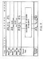
- FIGURE 7 is a table showing several examples of the calculation of decision by majority. As shown inFIGURE 7, the TV reception channels Ch-4 and Ch-6 have been received, around nine o'clock through the past four weeks. However, the TV reception channel Ch-6 has been dominantly received around the time. Then, the arithmetic circuit 18 decides by majority to take the TV reception channel Ch-6.
- a dominant tuning voltage data D2-ch e.g., the tuning voltage data D2-6 corresponding to the TV reception channel Ch-6 is output from the arithmetic circuit 18 when the power supply source of the TV receiver is turned on, around nine o'clock.
- the tuning voltage data D2-ch e.g., the tuning voltage data D2-6 output from the arithmetic circuit 18 is then applied to the tuning circuit 14 of the tuner 16 (Step 6E).
- a program at the TV reception channel e.g., Ch-6, which were dominantly received at the past times corresponding to the present time, e.g., around nine o'clock at that the power supply source of the TV receiver is turned on, is automatically received.
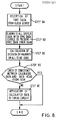
- FIGURE 8 is a flowchart showing the automatic reception channel selection routine.
- the system controller 12 is continuously supplied with the present time data D4 from the clock device 19 (Step 8A).
- the system controller 12 accesses the RAM 17a in every predetermined period, e.g., fifteen minutes, for receiving tuning voltage data D2-ch, which were previously stored for the past predetermined period, with time data just or closely responding to the present time data D4.
- all of the tuning voltage data D2-ch with the time data corresponding to the present time data D4 are read out from the RAM 17a (Step 8B).
- All of the tuning voltage data D2-ch thus read out are applied to the arithmetic circuit 18.
- the arithmetic circuit 18 performs the calculation of decision by majority on all of the tuning voltage data D2-ch (Step 8C).
- the calculation of decision by majority performed in the arithmetic circuit 18 during the automatic reception channel selection routine can also be described in reference to FIGURE 7.
- the TV reception channels Ch-4 and Ch-6 have been received, after nine o'clock till ten o'clock through the past four weeks.
- the TV reception channel Ch-6 has been dominantly received around the time.
- the arithmetic circuit 18 decides by majority to take the TV reception channel Ch-6 at every check operation, e.g., at the times of 9:15, 9:30 and 9:45.
- a dominant tuning voltage data D2-ch e.g., the operation data D2-6 corresponding to the TV reception channel Ch-6 is output from the arithmetic circuit 18 until ten o'clock.
- the tuning voltage data D2-ch e.g., the tuning voltage data D2-6 output from the arithmetic circuit 18 is then applied to the system controller 12.
- the system controller 12 compares the output from the arithmetic circuit 18, i.e., the tuning voltage data D2-6 with the other tuning voltage data D2-ch presently supplied from the ROM 13 (Step 8D).
- the tuning voltage data D2-6 output from the arithmetic circuit 18 coincides with the other tuning voltage data D2-ch presently supplied from the ROM 13.
- the system controller 12 supplies the tuning voltage data D2-6 to the tuning circuit 14 of the tuner 16.
- the reception of the TV channel Ch-6 is continued until ten o'clock.
- a dominant tuning voltage data D2-ch e.g., the tuning voltage data D2-8 corresponding to the TV reception channel Ch-8 is output from the arithmetic circuit 18 when it comes to ten o'clock.
- the tuning voltage data D2-ch e.g., the tuning voltage data D2-8 output from the arithmetic circuit 18 is then applied to the system controller 12.
- the system controller 12 compares the output from the arithmetic circuit 18, i.e., the tuning voltage data D2-8 with the other tuning voltage data D2-ch, i.e., D2-6 presently supplied from the ROM 13 (Step 8D).
- the tuning voltage data D2-8 output from the arithmetic circuit 18 differs with the other tuning voltage data D2-6 presently supplied from the ROM 13. Then, the system controller 12 takes the tuning voltage data D2-8 output from the arithmetic circuit 18 and supplies the tuning voltage data D2-8 to the tuning circuit 14 of the tuner 16 (Step 8E).
- the reception channel of the TV receiver is automatically changed to the channel Ch-8, which has been dominantly received for the past four weeks, at ten o'clock.
- An automatic volume setting operation routine of the system controller 12 of the embodiment during a normal TV reception state can be performed in similar to the automatic channel selection operation routine, as shown in FIGURE 8.
- the arithmetic circuit 18 is constituted by a calculation circuit which performs the calculation of decision by majority, as described before.
- the arithmetic circuit 18, however, can be constituted by other known calculation circuits which perform such an operation for picking out a prescribed one from a plurality of objects.
- the arithmetic circuit 18 can be constituted by a calculation circuit which performs a factor-load mean calculation on the operation data D2, such as the tuning voltage data D2-ch and the volume control voltage data D2-s.
- the data storage into the RAM 17a is performed by dividing to a plurality of unit periods, such as four weeks.
- the RAM 17 can be provided for storing the operation data for a single predetermined period, e.g., a week only or a day only.
- every operation data stored in the RAM 17a is associated to a different time data, one by one.
- the system controller 12 can directly access to the ram 16a for reading out a prescribed operation data therefrom without any help of the arithmetic circuit 18.
- the present invention can provide an extremely preferable reception control apparatus used for a television receiver.
Abstract
Description
- The present invention relates generally to a reception control apparatus used for a television receiver, and more particularly, to a reception control apparatus used for a television receiver, in which a reception control, e.g., a reception channel selection for a television receiver is automatically performed.
- In recent television receivers (referred as TV receivers), digital controls for a reception channel selection and a sound volume control are very popular.
- Such a TV receiver has a keyboard for manual controls of the TV receiver, a microcomputer for performing digital controls of the TV receiver, a memory storing a variety of control data and a tuner. The keyboard is mounted on a front panel or a remote controller of the TV receiver. The microcomputer reads out a suitable operation data, e.g., a tuning voltage data from the memory in response to an operation of the keyboard. The memory is generally comprised of a read only memory (referred as ROM hereafter).
- The operation data, e.g., the tuning voltage data read out from the ROM are converted to an analog tuning voltage by a conventional digital to analog converter (referred as D/A converter hereafter) and the analog tuning voltage is applied to the tuner. The tuner is generally comprised of a voltage synthesizer tuning circuit. The tuning voltage is applied to a variable capacitance diode in a resonant circuit of the tuner. Thus, the tuner performs a prescribed tuning for a desired TV reception channel designated by the keyboard.
- In such a conventional TV receiver, there has been developed a reception control apparatus which is equipped with another memory. The second memory is comprised of a random access memory (referred as RAM hereafter) which temporarily stores an operation data read out from the ROM upon operation of the keyboard or every predetermined time during the operation of the TV receiver.
- The operation data stored in the RAM are held even after a power shut-off of the TV receiver. For the purpose, the RAM is always activated by a suitable auxiliary power supply source like a battery. Thus, a prescribed channel reception at the last power shut-off can be automatically restored at the power turn-on operation of the TV receiver.
- An example of the conventional reception control apparatus for the TV receiver is shown in FIGURE 1. FIGURE 1 is a block diagram illustrating the conventional reception control apparatus. In FIGURE 1, a
keyboard 11 is coupled to asystem controller 12. Thekeyboard 11 is conventionally equipped with a power controller, a channel controller and a volume controller, but they are not shown in the drawing. The power controller controls the turn-on or the shut-off of a main power supply source of the TV receiver. The channel controller controls the selection of the TV reception channels. The volume controller controls the loudness of sound from the TV receiver. - There are at least two types for the channel controller. One type of the channel controller has a prescribed number of channel keys associated to the TV reception channels, i.e., Ch-1, Ch-2, ..., Ch-12, Ch-U, respectively. Another type of the channel controller has two keys, one for raising the count of the channel numbers and another for lowering the count of the channel numbers. The volume controller has two keys for increasing and decreasing sound volume.
- When any key on the
keyboard 11 is operated by a user, thekeyboard 11 outputs a reception control data D1 associated to the operated key. - The
system controller 12 is used to be constituted by a microcomputer. Necessary operations of thesystem controller 12 are performed by suitable operation softs programmed in the microcomputer for operations as described later or others. - When a specified key on the
keyboard 11 is operated thesystem controller 12 reads out a specified operation data D2 from anROM 13 coupled thereto, in response to the reception control data D1 associated to the operated key on thekeyboard 11. TheROM 13 stores a plurality of the operation data D2. The plurality of the operation data D2 include different voltage data, e.g., tuning voltage data D2-ch and volume voltage data D2-s. The tuning voltage data D2-ch, e.g., D2-1, D2-2, D2-3, ..., D2-12, D2-U correspond to the TV reception channels Ch-1, Ch-2, ..., Ch-12, Ch-U, respectively. - The tuning voltage data D2-ch and the volume voltage data D2-s read out from the
ROM 13 are applied to atuning circuit 14 and avolume control circuit 15 of atuner 16 through a D/A converter, respectively. The D/A converter is not shown in the drawing, but is comprised in thesystem controller 12 as a part of the microcomputer. The D/A converter converts the digital tuning voltage data D2-ch or the volume control voltage data D2-s to a corresponding analog tuning voltage D3, e.g., an analog tuning voltage D3-ch or an analog volume control voltage D3-s. - The tuning voltage D3-ch is applied to a variable impedance device such as a variable capacitance diode comprising a resonant circuit of the
tuning circuit 14. Thus, a desired TV reception channel is tuned by thetuning circuit 14 is response to the reception control data D1 designated to a specified channel key on thekeyboard 11. - The volume control voltage D3-s is applied to a
volume control circuit 15. Thus, a desired loudness is obtained in response to the reception control data D1 associated by the volume controller on thekeyboard 11. - The
system controller 12 is further coupled to anRAM 17 for temporarily storing the operation data D2 such the the tuning voltage data D2-ch and the volume control voltage data D2-s. The operation data D2 is applied to theRAM 17 at a prescribed time, as described later. - Referring now to FIGURE 2, a reception channel selection routine of the
system controller 12 in the course of the operation of the TV receiver. FIGURE 2 is a flowchart showing the selection routine. The user of the TV receiver operates the channel controller of thekeyboard 11 so that a prescribed reception control data D1 corresponding to his or her desired TV channel is applied to the system controller 12 (Step 2A). - The
system controller 12 reads out a specified tuning voltage data D2-ch from theROM 13 in response to the reception control data D1 applied from the keyboard 11 (Step 2B). The D/A converter comprised in thesystem controller 12 converts the tuning voltage data D2-ch of digital configuration to a corresponding tuning voltage D3-ch of analog configuration and then applies the tuning voltage D3-ch to thetuning circuit 14 of the tuner 16 (Step 2C). Thus, the desired TV channel program is received by the TV receiver. - The
system controller 12 further applies the tuning voltage data D2-ch to theRAM 17 when the channel controller of thekeyboard 11 is operated (Step 2D). The tuning voltage data D2-ch is temporarily stored in the RAM 17 (Step 2E). But, the tuning voltage data D2-ch, e.g., D2-3 stored in theRAM 17 is replaced by another tuning voltage data D2-ch, e.g., D2-5 when another operation for the channel controller of thekeyboard 11 is made. - The
RAM 17 is always activated by an auxiliary power supply source (not shown). Thus, the tuning voltage data D2-ch stored in theRAM 17 is held even after a main power supply source for the TV receiver is shut-off by the operation of the power controller on thekeyboard 11. - Referring now to FIGURE 3, an operation routine of the
system controller 12 at the power turn-on operation of the TV receiver. FIGURE 3 is a flowchart showing the operation routine. For the power turn-on of the TV receiver, the power controller on thekeyboard 11 is operated by the user (Step 3A). Thus, a prescribed reception control data D1 is applied to thesystem controller 12. Thesystem controller 12 automatically accesses theRAM 17 upon receipt of the reception control data D1 (Step 3B). Then, thesystem controller 12 reads out a tuning voltage data D2-ch from theRAM 17, which has been held at the last power shut-off operation of the TV receiver. - The D/A converter in the
system controller 12 converts the tuning voltage data D2-ch of the digital configuration to a tuning voltage D3-ch of analog configuration and then applies the tuning voltage D3-ch to thetuning circuit 15 of the tuner 16 (Step 3C). Thus, a program at the TV channel received just before the last power shut-off operation is received by the TV receiver. - However, the conventional channel selection apparatus has a drawback as follows.
- Generally, users have their own habit on the TV channel receptions through a day or a week. In their reception patterns due to the habit, desired reception channels are used to be different with each other, time by time in a day or a week. Therefore, a user wish to receive different TV channels for different times in a day or a week.
- The conventional channel selection apparatus for a TV receiver is unable to satisfy such a demand according to the user's habit or the reception pattern in a day or a week.
- It is, therefore, an object of the present invention to provide a channel selection apparatus for a TV receiver which is able to automatically select a predetermined TV channel along with the user's habit or reception pattern for a prescribed period.
- In order to achieve the above object, a channel selection apparatus used for a TV receiver for automatically selecting a predetermined TV channel along with a user's habit or reception pattern for a prescribed period includes an input device for commanding reception control data for the channel selection, a clock device for generating a time data, a memory device for storing reception control data supplied from the input device for a predetermined period together with time data responding to the reception control data to be stored, a control device for controlling the memory device for a writing reception control data and its responding time data thereto and a reading out predetermined reception control data with time data responding to the present time and an output device responsive to the control device for receiving the reception control data.
- A more complete appreciation of the invention and many of the attendant advantages thereof will be readily obtained as the same becomes better understood by reference to the following detailed description when considered in connection with the accompanying drawings, wherein:
- FIGURE 1 is a block diagram showing an example of a conventional reception control apparatus for a TV receiver;
- FIGURE 2 is a flowchart showing a reception channel selection routine performed by the
system controller 12 of FIGURE 1; - FIGURE 3 is a flowchart showing another operation routine performed by the
system controller 12 of FIGURE 1 at a power turn-on operation of a TV receiver; - FIGURE 4 is a block diagram showing an embodiment of a reception control apparatus for a TV receiver according to the present invention;
- FIGURE 5 is a flowchart showing a data storage operation routine performed by the
system controller 12 of FIGURE 4 during operation of the TV receiver; - FIGURE 6 is a flowchart showing an operation routine performed by the
system controller 12 of FIGURE 4 at the power turn-on operation of the TV receiver; - FIGURE 7 is a table showing several examples of a decision by majority calculation performed by the
arithmetic circuit 18 of FIGURE 4; and - FIGURE 8 is a flowchart showing an automatic reception channel selection routine performed by the
system controller 12 of FIGURE 4 during operation of the TV receiver. - The present invention will be described in detail with reference to FIGURES 4 through 8. Throughout drawings, reference numerals or letters used in FIGURES 1 to 3 (Prior Arts) will be used to designate like or equivalent elements or steps for simplicity of explanation.
- Referring now to FIGURE 4, an embodiment of the reception control apparatus for a TV receiver according to the present invention will be described in detail. FIGURE 4 is a block diagram illustrating the embodiment of the reception control apparatus. In FIGURE 4, a
keyboard 11 is coupled to asystem controller 12. Thekeyboard 11 has a similar construction as thekeyboard 11 of the conventional reception control apparatus, as shown in FIGURE 1. That is, thekeyboard 11 is equipped with a power controller, a channel controller and a volume controller. When any key on thekeyboard 11 is operated by a user, thekeyboard 11 outputs a reception control data D1 associated to the operated key. - The
system controller 12 is used to be constituted by a microcomputer, in similar to the conventional reception control apparatus. Necessary operations of thesystem controller 12 for operations as described later or others are performed by suitable operation softs programmed in the microcomputer. - The
system controller 12 reads out a specified operation data D2 from anROM 13 coupled to thesystem controller 12 in response to the reception control data D1 supplied from thekeyboard 11. TheROM 13 stores a plurality of the operation data D2 such as tuning voltage data D2-ch, the volume control voltage data D2-s and other necessary operation data. The operation data D2, e.g., the tuning voltage data D2-ch include different voltage data D2-1, D2-2, D2-3, ..., D2-12, D2-U and other data, which correspond to the TV reception channels Ch-1, Ch-2, ..., Ch-12, Ch-U, respectively, as described before. - The tuning voltage data D2-ch read out from the
ROM 13 is applied to atuning circuit 14 of atuner 16 through a D/A converter. The volume control voltage data D2-s read out from theROM 13 is applied to avolume control circuit 15 of atuner 16 through the D/A converter. The D/A converter is comprised in thesystem controller 12 as a part of the microcomputer, in similar to the conventional reception control apparatus. The D/A converter converts the digital voltage data D2 such as the tuning voltage data D2-ch or the volume control voltage data D2-s to a corresponding analog tuning voltage D3, such as a tuning voltage D3-ch or a volume control voltage D3-s. - The tuning voltage D3-ch is applied to a variable impedance device such as a variable capacitance diode comprising a resonant circuit of the
tuning circuit 14. Thus, a desired TV reception channel is tuned by thetuning circuit 14 in response to the reception control data D1 designated by the channel controller on thekeyboard 11. - The volume control voltage D3-s is applied to the
volume control circuit 15 of thetuner 16. Thus, a desired loudness of sound is obtained from the TV receiver in response to the reception control data D1 designated by the volume controller on thekeyboard 11. - The
system controller 12 is further coupled to anRAM 17a for storing a plurality of the operation data D2 such as the tuning voltage data D2-ch and the volume control voltage data D2-s through anarithmetic circuit 18. TheRAM 17a has a sufficient capacity of memory area for storing the operation data D2 for a prescribed period, e.g., four weeks. The operation data D2 such as the tuning voltage data D2-ch and the volume control voltage data D2-s applied from thesystem controller 12 to theRAM 17a passes through thearithmetic circuit 16 as they are without any change. - The
system controller 12 is further coupled to aclock device 19. Theclock device 19 is constituted by a clock pulse generator and digital processing circuits such as pulse dividers, as conventional clock devices used in many fields. A clock pulse generated by the clock generator is processed through the digital processing circuits so that theclock device 19 continuously generates a present time data D4 of digital configuration. The present time data D4 is supplied to thesystem controller 12. - A reception channel selection routine of the
system controller 12 in the course of the operation of the TV receiver is performed, in similar to the conventional reception control apparatus, as shown in FIGURE 2. Therefore, the channel selection routine of thesystem controller 12 of the embodiment will be omitted from following descriptions. - Referring now to FIGURE 5, an operation routine of the
system controller 12 of the embodiment for a tuning voltage data storage to theRAM 17a will be described. FIGURE 5 is a flowchart showing the tuning voltage data storage operation routine. Thesystem controller 12 is continuously supplied with the present time data D4 from the clock device 19 (Step 5A). Thesystem controller 12 accesses theROM 13 in every predetermined period, e.g., fifteen minutes, for receiving a tuning voltage data D2-ch at the times (Step 5B). Thesystem controller 12 then supplies the tuning voltage data D2-ch together with the time data D4 associated to the tuning voltage data D2-ch. Thus, the tuning voltage data D2-ch and the time data D4 are consecutively stored in theRAM 17a in every fifteen minutes (Step 5C). - An operation routine of the
system controller 12 of the embodiment for storage of volume control voltage data to theRAM 17a can be performed in similar to the operation routine of the tuning voltage data storage, as shown in FIGURE 5. - Referring now to FIGURE 6, an operation routine of the
system controller 12 at the power turn-on operation of the TV receiver will be described. FIGURE 6 is a flowchart showing the operation routine. At the power turn-on of the TV receiver, the power controller on thekeyboard 11 is operated by the user (Step 6A). Thus, a prescribed reception control data D1 associated to the power controller is applied to thesystem controller 12. Thesystem controller 12 automatically accesses theRAM 17a upon receipt of the reception control data D1 (Step 6B). Then, all of prescribed tuning voltage data D2-ch, which were previously stored for a past predetermined period, with time data just or closely responding to the present time data D4 are read out from theRAM 17a (Step 6C). - All of the tuning voltage data D2-ch thus read out are applied to the
arithmetic circuit 18. Thearithmetic circuit 18 performs a calculation of decision by majority on all of the tuning voltage data D2-ch (Step 6D). - An automatic volume setting operation routine of the
system controller 12 of the embodiment at the power turn-on operation of the TV receiver can be performed in similar to the automatic channel selection routine at the power turn-on operation, as shown in FIGURE 6. - Some examples of the calculation of decision by majority performed in the
arithmetic circuit 18 are illustrated in FIGURE 7. FIGURE 7 is a table showing several examples of the calculation of decision by majority. As shown inFIGURE 7, the TV reception channels Ch-4 and Ch-6 have been received, around nine o'clock through the past four weeks. However, the TV reception channel Ch-6 has been dominantly received around the time. Then, thearithmetic circuit 18 decides by majority to take the TV reception channel Ch-6. - Thus, a dominant tuning voltage data D2-ch, e.g., the tuning voltage data D2-6 corresponding to the TV reception channel Ch-6 is output from the
arithmetic circuit 18 when the power supply source of the TV receiver is turned on, around nine o'clock. - The tuning voltage data D2-ch, e.g., the tuning voltage data D2-6 output from the
arithmetic circuit 18 is then applied to thetuning circuit 14 of the tuner 16 (Step 6E). Thus, a program at the TV reception channel, e.g., Ch-6, which were dominantly received at the past times corresponding to the present time, e.g., around nine o'clock at that the power supply source of the TV receiver is turned on, is automatically received. - Referring now to FIGURE 8, an automatic reception channel selection routine of the
system controller 12 during a normal TV reception state will be described. FIGURE 8 is a flowchart showing the automatic reception channel selection routine. Thesystem controller 12 is continuously supplied with the present time data D4 from the clock device 19 (Step 8A). Thesystem controller 12 accesses theRAM 17a in every predetermined period, e.g., fifteen minutes, for receiving tuning voltage data D2-ch, which were previously stored for the past predetermined period, with time data just or closely responding to the present time data D4. Thus, all of the tuning voltage data D2-ch with the time data corresponding to the present time data D4 are read out from theRAM 17a (Step 8B). - All of the tuning voltage data D2-ch thus read out are applied to the
arithmetic circuit 18. Thearithmetic circuit 18 performs the calculation of decision by majority on all of the tuning voltage data D2-ch (Step 8C). - The calculation of decision by majority performed in the
arithmetic circuit 18 during the automatic reception channel selection routine can also be described in reference to FIGURE 7. As shown in FIGURE 7, the TV reception channels Ch-4 and Ch-6 have been received, after nine o'clock till ten o'clock through the past four weeks. However, the TV reception channel Ch-6 has been dominantly received around the time. Then, thearithmetic circuit 18 decides by majority to take the TV reception channel Ch-6 at every check operation, e.g., at the times of 9:15, 9:30 and 9:45. - Thus, a dominant tuning voltage data D2-ch, e.g., the operation data D2-6 corresponding to the TV reception channel Ch-6 is output from the
arithmetic circuit 18 until ten o'clock. The tuning voltage data D2-ch, e.g., the tuning voltage data D2-6 output from thearithmetic circuit 18 is then applied to thesystem controller 12. Thesystem controller 12 compares the output from thearithmetic circuit 18, i.e., the tuning voltage data D2-6 with the other tuning voltage data D2-ch presently supplied from the ROM 13 (Step 8D). In this example, the tuning voltage data D2-6 output from thearithmetic circuit 18 coincides with the other tuning voltage data D2-ch presently supplied from theROM 13. Thesystem controller 12 supplies the tuning voltage data D2-6 to thetuning circuit 14 of thetuner 16. Thus, the reception of the TV channel Ch-6 is continued until ten o'clock. - According to the table of FIGURE 7, only the TV reception channel Ch-8 has been received, for some hours from ten o'clock through the past four weeks. Then the
arithmetic circuit 18 decides by majority to take the TV reception channel Ch-8. - Thus, a dominant tuning voltage data D2-ch, e.g., the tuning voltage data D2-8 corresponding to the TV reception channel Ch-8 is output from the
arithmetic circuit 18 when it comes to ten o'clock. The tuning voltage data D2-ch, e.g., the tuning voltage data D2-8 output from thearithmetic circuit 18 is then applied to thesystem controller 12. Thesystem controller 12 compares the output from thearithmetic circuit 18, i.e., the tuning voltage data D2-8 with the other tuning voltage data D2-ch, i.e., D2-6 presently supplied from the ROM 13 (Step 8D). In this example, the tuning voltage data D2-8 output from thearithmetic circuit 18 differs with the other tuning voltage data D2-6 presently supplied from theROM 13. Then, thesystem controller 12 takes the tuning voltage data D2-8 output from thearithmetic circuit 18 and supplies the tuning voltage data D2-8 to thetuning circuit 14 of the tuner 16 (Step 8E). Thus, the reception channel of the TV receiver is automatically changed to the channel Ch-8, which has been dominantly received for the past four weeks, at ten o'clock. - An automatic volume setting operation routine of the
system controller 12 of the embodiment during a normal TV reception state can be performed in similar to the automatic channel selection operation routine, as shown in FIGURE 8. - In the embodiment of the reception control apparatus for a TV receiver, as shown in FIGURE 4, the
arithmetic circuit 18 is constituted by a calculation circuit which performs the calculation of decision by majority, as described before. Thearithmetic circuit 18, however, can be constituted by other known calculation circuits which perform such an operation for picking out a prescribed one from a plurality of objects. For example, thearithmetic circuit 18 can be constituted by a calculation circuit which performs a factor-load mean calculation on the operation data D2, such as the tuning voltage data D2-ch and the volume control voltage data D2-s. - In the embodiment of the reception control apparatus for a TV receiver, as shown in FIGURE 4, the data storage into the
RAM 17a is performed by dividing to a plurality of unit periods, such as four weeks. However, theRAM 17 can be provided for storing the operation data for a single predetermined period, e.g., a week only or a day only. In this case, every operation data stored in theRAM 17a is associated to a different time data, one by one. As a result, thesystem controller 12 can directly access to the ram 16a for reading out a prescribed operation data therefrom without any help of thearithmetic circuit 18. - As described above, the present invention can provide an extremely preferable reception control apparatus used for a television receiver.
- While there has been illustrated and described what are at present considered to be preferred embodiments of the present invention, it will be understood by those skilled in the art that various changes and modifications may be made, and equivalents may be substituted for elements thereof without departing from the true scope of the invention. In addition, many modifications may be made to adapt a particular situation or material to the teaching of the present invention without departing from the central scope thereof. Therefore, it is intended that this invention not be limited to the particular embodiment disclosed as the best mode contemplated for carrying out this invention, but that the invention include all embodiments falling within the scope of the appended claims.
- The foregoing description and the drawings are regarded by the applicant as including a variety of individually inventive concepts, some of which may lie partially or wholly outside the scope of some or all of the following claims. The fact that the applicant has chosen at the time of filing of the present application to restrict the claimed scope of protection in accordance with the following claims is not to be taken as a disclaimer or alternative inventive concepts that are included in the contents of the application and could be defined by claims differing in scope from the following claims, which different claims may be adopted subsequently during prosecution, for example for the purposes of a divisional application.
Claims (8)
an input means (11, 13) for commanding reception control data;
memory means (17a) for storing reception control data supplied from the input means (11, 13);
means (12) for controlling the memory means (17a) for writing reception control data and reading reception control data; and
output means (16) responsive to the control means (12) for receiving the reception control data;
characterized in that the the reception control apparatus further comprises a clock means (19) for generating time data, and wherein the control means (12) controls the memory means (17a) for writing a plurality of the reception control data for a predetermined period together with their corresponding time data and reading the predetermined reception control data with time data corresponding to the present time.
Applications Claiming Priority (2)
| Application Number | Priority Date | Filing Date | Title |
|---|---|---|---|
| JP139303/87 | 1987-06-02 | ||
| JP62139303A JP2511040B2 (en) | 1987-06-02 | 1987-06-02 | Tuning device |
Publications (4)
| Publication Number | Publication Date |
|---|---|
| EP0294191A2 true EP0294191A2 (en) | 1988-12-07 |
| EP0294191A3 EP0294191A3 (en) | 1990-06-27 |
| EP0294191B1 EP0294191B1 (en) | 1995-04-26 |
| EP0294191B2 EP0294191B2 (en) | 1998-08-26 |
Family
ID=15242146
Family Applications (1)
| Application Number | Title | Priority Date | Filing Date |
|---|---|---|---|
| EP88305025A Expired - Lifetime EP0294191B2 (en) | 1987-06-02 | 1988-06-02 | Reception control apparatus for a television receiver |
Country Status (5)
| Country | Link |
|---|---|
| US (1) | US4954899A (en) |
| EP (1) | EP0294191B2 (en) |
| JP (1) | JP2511040B2 (en) |
| KR (1) | KR940000937B1 (en) |
| DE (1) | DE3853650T3 (en) |
Cited By (5)
| Publication number | Priority date | Publication date | Assignee | Title |
|---|---|---|---|---|
| GB2230668A (en) * | 1989-03-24 | 1990-10-24 | Hashimoto Corp | Automatic selective viewing/listening device for TV, radio or the like |
| EP0575956A2 (en) * | 1992-06-26 | 1993-12-29 | Thomson Consumer Electronics, Inc. | Favourite channel selection using extended keypress duration |
| WO1996019079A1 (en) * | 1994-12-15 | 1996-06-20 | Philips Electronics N.V. | Television receiver |
| WO2000049802A1 (en) * | 1999-02-17 | 2000-08-24 | Index Systems, Inc. | Systems and methods for controlling the tuning of the entry channel of a television device |
| WO2012158128A1 (en) * | 2011-05-19 | 2012-11-22 | Echostar Ukraine L. L. C. | Apparatus, systems and methods for a media device pre-operation |
Families Citing this family (18)
| Publication number | Priority date | Publication date | Assignee | Title |
|---|---|---|---|---|
| US4965825A (en) | 1981-11-03 | 1990-10-23 | The Personalized Mass Media Corporation | Signal processing apparatus and methods |
| USRE47642E1 (en) | 1981-11-03 | 2019-10-08 | Personalized Media Communications LLC | Signal processing apparatus and methods |
| US7831204B1 (en) | 1981-11-03 | 2010-11-09 | Personalized Media Communications, Llc | Signal processing apparatus and methods |
| US5054071A (en) * | 1989-02-03 | 1991-10-01 | Scientific-Atlanta, Inc. | Volume control for optimum television stereo separation |
| US5157496A (en) * | 1989-09-25 | 1992-10-20 | Casio Computer Co., Ltd. | Portable television receiver equipped with remote controller |
| JPH03154585A (en) * | 1989-11-13 | 1991-07-02 | Pioneer Electron Corp | Catv terminal equipment |
| JPH03250912A (en) * | 1990-02-28 | 1991-11-08 | Victor Co Of Japan Ltd | Channel selector |
| US5293357A (en) * | 1990-09-10 | 1994-03-08 | The Superguide Corporation | Method and apparatus for controlling a television program recording device |
| JP2826204B2 (en) * | 1991-04-30 | 1998-11-18 | シャープ株式会社 | Receiver |
| KR950014578B1 (en) * | 1993-05-20 | 1995-12-08 | 엘지전자주식회사 | Auto channel arranging method |
| US5566237A (en) * | 1994-02-03 | 1996-10-15 | Dobbs-Stanford Corporation | Time zone equalizer |
| JPH07321679A (en) * | 1994-05-24 | 1995-12-08 | Pioneer Electron Corp | Multiplex broadcast channel selection method and receiver using the method |
| US5896572A (en) * | 1994-10-31 | 1999-04-20 | Motorola, Inc. | Method of adaptive channel acquisition at a subscriber unit |
| US5734971A (en) * | 1995-05-15 | 1998-03-31 | Delco Electronics Corporation | Adaptive system for determining radio frequency at vehicle start-up |
| KR0182004B1 (en) * | 1995-11-28 | 1999-05-01 | 김광호 | Channel hopping time reduction method in mpeg 2 system decoder |
| DE19805043B4 (en) * | 1998-02-09 | 2013-10-10 | Harman Becker Automotive Systems Gmbh | Broadcast receiver and method of operating such |
| KR100253252B1 (en) * | 1998-02-27 | 2000-04-15 | 구자홍 | Analysis and search method for user looking and listening habit of aerial frequency broadcasting |
| JP3389566B2 (en) * | 2000-12-01 | 2003-03-24 | 三洋電機株式会社 | Radio receiver |
Citations (2)
| Publication number | Priority date | Publication date | Assignee | Title |
|---|---|---|---|---|
| US4081753A (en) * | 1976-12-13 | 1978-03-28 | Miller Arthur O | Automatic programming system for television receivers |
| JPS5829276A (en) * | 1981-08-13 | 1983-02-21 | Akiyoshi Kinoshita | Television receiver |
Family Cites Families (5)
| Publication number | Priority date | Publication date | Assignee | Title |
|---|---|---|---|---|
| US3800230A (en) * | 1972-08-14 | 1974-03-26 | Marks Brothers Prod Inc | Digital programmer for receivers |
| JPS53654A (en) * | 1976-06-22 | 1978-01-06 | Youei Seisakushiyo Kk | Water boilder interlocked to ventilating fan |
| US4228543A (en) * | 1978-03-24 | 1980-10-14 | Jackson Joseph N | Programmable television receiver controllers |
| JPS58182326A (en) * | 1982-04-19 | 1983-10-25 | Matsushita Electric Ind Co Ltd | Program memory device |
| US4706121B1 (en) * | 1985-07-12 | 1993-12-14 | Insight Telecast, Inc. | Tv schedule system and process |
-
1987
- 1987-06-02 JP JP62139303A patent/JP2511040B2/en not_active Expired - Lifetime
-
1988
- 1988-06-01 US US07/200,970 patent/US4954899A/en not_active Expired - Lifetime
- 1988-06-02 KR KR1019880006606A patent/KR940000937B1/en not_active IP Right Cessation
- 1988-06-02 DE DE3853650T patent/DE3853650T3/en not_active Expired - Lifetime
- 1988-06-02 EP EP88305025A patent/EP0294191B2/en not_active Expired - Lifetime
Patent Citations (2)
| Publication number | Priority date | Publication date | Assignee | Title |
|---|---|---|---|---|
| US4081753A (en) * | 1976-12-13 | 1978-03-28 | Miller Arthur O | Automatic programming system for television receivers |
| JPS5829276A (en) * | 1981-08-13 | 1983-02-21 | Akiyoshi Kinoshita | Television receiver |
Non-Patent Citations (2)
| Title |
|---|
| IEEE TRANSACTIONS ON CONSUMER ELECTRONICS, vol. 26, no. 2, may 1980, New York, US; K. KARSTAD: "Microprocessor control for color-TV receivers", pages 149-155 * |
| PATENT ABSTRACTS OF JAPAN, vol. 7, no. 107 (E-147)[1252], 11th May 1983; & JP-A-58 29 276 (KINOSHITA) 21-02-1983 * |
Cited By (11)
| Publication number | Priority date | Publication date | Assignee | Title |
|---|---|---|---|---|
| GB2230668A (en) * | 1989-03-24 | 1990-10-24 | Hashimoto Corp | Automatic selective viewing/listening device for TV, radio or the like |
| GB2230668B (en) * | 1989-03-24 | 1994-05-25 | Hashimoto Corp | Automatic selective viewing/listening device for TV,radio or the like |
| EP0575956A2 (en) * | 1992-06-26 | 1993-12-29 | Thomson Consumer Electronics, Inc. | Favourite channel selection using extended keypress duration |
| EP0575956A3 (en) * | 1992-06-26 | 1994-05-11 | Thomson Consumer Electronics | Favourite channel selection using extended keypress duration |
| TR27324A (en) * | 1992-06-26 | 1995-01-12 | Thomson Consumer Electronics | Long press on the button to select the favorite channel. |
| SG93766A1 (en) * | 1992-06-26 | 2003-01-21 | Thomson Consumer Electronics | Favourite channel selection using extended keypress |
| WO1996019079A1 (en) * | 1994-12-15 | 1996-06-20 | Philips Electronics N.V. | Television receiver |
| WO2000049802A1 (en) * | 1999-02-17 | 2000-08-24 | Index Systems, Inc. | Systems and methods for controlling the tuning of the entry channel of a television device |
| WO2012158128A1 (en) * | 2011-05-19 | 2012-11-22 | Echostar Ukraine L. L. C. | Apparatus, systems and methods for a media device pre-operation |
| US8955003B2 (en) | 2011-05-19 | 2015-02-10 | Echostar Technologies L.L.C. | Apparatus, systems and methods for a media device pre-operation |
| US10079992B2 (en) | 2011-05-19 | 2018-09-18 | Echostar Ukraine Llc | Apparatus, systems and methods for a media device pre-operation |
Also Published As
| Publication number | Publication date |
|---|---|
| JPS63302697A (en) | 1988-12-09 |
| KR890001374A (en) | 1989-03-20 |
| EP0294191B2 (en) | 1998-08-26 |
| EP0294191B1 (en) | 1995-04-26 |
| DE3853650D1 (en) | 1995-06-01 |
| DE3853650T2 (en) | 1995-08-31 |
| US4954899A (en) | 1990-09-04 |
| JP2511040B2 (en) | 1996-06-26 |
| EP0294191A3 (en) | 1990-06-27 |
| DE3853650T3 (en) | 1998-10-29 |
| KR940000937B1 (en) | 1994-02-04 |
Similar Documents
| Publication | Publication Date | Title |
|---|---|---|
| EP0294191A2 (en) | Reception control apparatus for a television receiver | |
| US4279035A (en) | Channel number entry system | |
| KR940000998A (en) | Favorite channel selector with extended key presses | |
| US4525866A (en) | Stack memory tuning | |
| US5157496A (en) | Portable television receiver equipped with remote controller | |
| GB1581525A (en) | Frequency synthesis control system | |
| JPS5927124B2 (en) | radio receiver | |
| US4223352A (en) | Control circuit | |
| US6452608B1 (en) | Process and device for displaying information on a screen | |
| CA1129126A (en) | Tuning system including a memory for storing tuning information with user controls arranged to facilitate its programming | |
| EP0125717A1 (en) | Broadcast receiver with automatic broadcast station storage | |
| US5048119A (en) | Broadcast receiver for radio or television signals with storage and interchange of preset stations | |
| US4466126A (en) | Tuner apparatus | |
| US5465403A (en) | Shortwave radio receiver with timer reception mode | |
| JP2002142278A (en) | Method for controlling equipment and the same equipment and remote control transmitter | |
| JP2935445B2 (en) | Broadcast receiver | |
| GB2076242A (en) | Television system scheduler | |
| JP2941084B2 (en) | How to automatically preset electronic devices | |
| JPH01236826A (en) | Automatic channel selection device for television receiver and the like | |
| KR950005278B1 (en) | Tv channel select method and apparatus | |
| KR960005933B1 (en) | Channel selecting apparatus | |
| JPS6012369Y2 (en) | Backup power supply circuit | |
| JPS5853773Y2 (en) | Time and reception channel setting device | |
| JP2001517885A (en) | Adjustable remote control for electrical equipment with several control functions | |
| KR100196861B1 (en) | Method for automatically changing channel in a video system |
Legal Events
| Date | Code | Title | Description |
|---|---|---|---|
| PUAI | Public reference made under article 153(3) epc to a published international application that has entered the european phase |
Free format text: ORIGINAL CODE: 0009012 |
|
| 17P | Request for examination filed |
Effective date: 19880621 |
|
| AK | Designated contracting states |
Kind code of ref document: A2 Designated state(s): DE GB |
|
| PUAL | Search report despatched |
Free format text: ORIGINAL CODE: 0009013 |
|
| AK | Designated contracting states |
Kind code of ref document: A3 Designated state(s): DE GB |
|
| 17Q | First examination report despatched |
Effective date: 19920520 |
|
| GRAA | (expected) grant |
Free format text: ORIGINAL CODE: 0009210 |
|
| AK | Designated contracting states |
Kind code of ref document: B1 Designated state(s): DE GB |
|
| REF | Corresponds to: |
Ref document number: 3853650 Country of ref document: DE Date of ref document: 19950601 |
|
| PLBQ | Unpublished change to opponent data |
Free format text: ORIGINAL CODE: EPIDOS OPPO |
|
| PLBI | Opposition filed |
Free format text: ORIGINAL CODE: 0009260 |
|
| PLBF | Reply of patent proprietor to notice(s) of opposition |
Free format text: ORIGINAL CODE: EPIDOS OBSO |
|
| 26 | Opposition filed |
Opponent name: PHILIPS ELECTRONICS N.V. Effective date: 19960126 |
|
| PLBF | Reply of patent proprietor to notice(s) of opposition |
Free format text: ORIGINAL CODE: EPIDOS OBSO |
|
| PLAW | Interlocutory decision in opposition |
Free format text: ORIGINAL CODE: EPIDOS IDOP |
|
| PUAH | Patent maintained in amended form |
Free format text: ORIGINAL CODE: 0009272 |
|
| STAA | Information on the status of an ep patent application or granted ep patent |
Free format text: STATUS: PATENT MAINTAINED AS AMENDED |
|
| 27A | Patent maintained in amended form |
Effective date: 19980826 |
|
| AK | Designated contracting states |
Kind code of ref document: B2 Designated state(s): DE GB |
|
| REG | Reference to a national code |
Ref country code: GB Ref legal event code: 746 Effective date: 19981010 |
|
| REG | Reference to a national code |
Ref country code: GB Ref legal event code: IF02 |
|
| PGFP | Annual fee paid to national office [announced via postgrant information from national office to epo] |
Ref country code: DE Payment date: 20070531 Year of fee payment: 20 |
|
| PGFP | Annual fee paid to national office [announced via postgrant information from national office to epo] |
Ref country code: GB Payment date: 20070530 Year of fee payment: 20 |
|
| REG | Reference to a national code |
Ref country code: GB Ref legal event code: PE20 Expiry date: 20080601 |
|
| PLAB | Opposition data, opponent's data or that of the opponent's representative modified |
Free format text: ORIGINAL CODE: 0009299OPPO |
|
| PG25 | Lapsed in a contracting state [announced via postgrant information from national office to epo] |
Ref country code: GB Free format text: LAPSE BECAUSE OF EXPIRATION OF PROTECTION Effective date: 20080601 |