EP0299902A2 - Blast-resistant container - Google Patents
Blast-resistant container Download PDFInfo
- Publication number
- EP0299902A2 EP0299902A2 EP88630030A EP88630030A EP0299902A2 EP 0299902 A2 EP0299902 A2 EP 0299902A2 EP 88630030 A EP88630030 A EP 88630030A EP 88630030 A EP88630030 A EP 88630030A EP 0299902 A2 EP0299902 A2 EP 0299902A2
- Authority
- EP
- European Patent Office
- Prior art keywords
- outer housing
- blast
- container according
- compressible layer
- vermiculite
- Prior art date
- Legal status (The legal status is an assumption and is not a legal conclusion. Google has not performed a legal analysis and makes no representation as to the accuracy of the status listed.)
- Granted
Links
Images
Classifications
-
- F—MECHANICAL ENGINEERING; LIGHTING; HEATING; WEAPONS; BLASTING
- F42—AMMUNITION; BLASTING
- F42B—EXPLOSIVE CHARGES, e.g. FOR BLASTING, FIREWORKS, AMMUNITION
- F42B39/00—Packaging or storage of ammunition or explosive charges; Safety features thereof; Cartridge belts or bags
- F42B39/24—Shock-absorbing arrangements in packages, e.g. for shock waves
-
- B—PERFORMING OPERATIONS; TRANSPORTING
- B65—CONVEYING; PACKING; STORING; HANDLING THIN OR FILAMENTARY MATERIAL
- B65F—GATHERING OR REMOVAL OF DOMESTIC OR LIKE REFUSE
- B65F1/00—Refuse receptacles; Accessories therefor
- B65F1/14—Other constructional features; Accessories
-
- B—PERFORMING OPERATIONS; TRANSPORTING
- B65—CONVEYING; PACKING; STORING; HANDLING THIN OR FILAMENTARY MATERIAL
- B65F—GATHERING OR REMOVAL OF DOMESTIC OR LIKE REFUSE
- B65F1/00—Refuse receptacles; Accessories therefor
- B65F1/14—Other constructional features; Accessories
- B65F1/141—Supports, racks, stands, posts or the like for holding refuse receptacles
-
- B—PERFORMING OPERATIONS; TRANSPORTING
- B65—CONVEYING; PACKING; STORING; HANDLING THIN OR FILAMENTARY MATERIAL
- B65F—GATHERING OR REMOVAL OF DOMESTIC OR LIKE REFUSE
- B65F2210/00—Equipment of refuse receptacles
- B65F2210/13—Double walls
-
- B—PERFORMING OPERATIONS; TRANSPORTING
- B65—CONVEYING; PACKING; STORING; HANDLING THIN OR FILAMENTARY MATERIAL
- B65F—GATHERING OR REMOVAL OF DOMESTIC OR LIKE REFUSE
- B65F2220/00—Properties of refuse receptacles
- B65F2220/104—Bomb resistant
Definitions
- the present invention relates to blast-resistant containers, and particularly to such containers for receiving an explosive or explosive-suspect article, such as a hidden bomb, for preventing or minimizing damage in the event the article explodes.
- Blast-resistant containers are now widely used for holding an explosive, or an explosive-suspect article, in order to either transport the article to a place where it can be safely detonated, or to permit its safe detonation within the container itself.
- the known blast-resistant containers presently in use are generally of very thick, heavy and bulky construction in order to be able to withstand the blast should the article placed within it explode.
- An object of the present invention is to provide a blast-resistant container which is of simpler, lighter and less bulky construction than the blast-resistant containers heretofore used.
- a blast-resistant container for receiving an explosive or explosive-suspect article, comprising: a high-strength outer housing; characterized in that said housing includes an inner compressible layer of a mixture including vermiculite in a binder effective to space the article from the outer housing, to absorb energy of the blast before transmitted to the outer housing, to distribute the blast forces over a larger surface area of the outer housing, and to impart resistance to the penetration of fragments to the outer housing.
- Vermiculite is a micaceous hydrated silicate related to the chlorites and is normally used as heat insulation and/or for starting plant seeds and cuttings. Good results have been obtained when the vermiculite in the inner compressible layer of the present invention has an average small-dimension particle size of from 5 to 10 mm, and wherein the binder is plaster, or cement.
- a compressible layer including vermiculite, plaster or cement, and water has been found to be particularly effective wherein the vermiculite is present from 2:1 to 10:1 parts by volume. Decreasing the quantity of the vermiculite to a ratio of less than 2:1 produces high resistance to penetration of fragments but low absorption of the energy of the blast before it is transmitted to the outer housing; whereas increasing the ratio of the vermiculite over 10:1 produces high energy absorption but very little penetration resistance of the fragments. Best results have been obtained when the inner compressible layer was a mixture of about 6:1 of vermiculite and plaster or cement plus a quantity of water equal to about 10% in volume of the total mix.
- the outer housing is open at the top and includes a removable cover closing its open top.
- This embodiment is particularly useful as a trash bin to be located in public places to provide some degree of protection to the public in case an explosive device is inserted into it.
- the outer housing is formed with an opening in the side and includes a door which is movable to either an open position or to a closed position with respect to the side opening.
- Such a container construction is more particularly useful to hold an explosive-suspect article while being transported to a safe place for detonation, or for detonation within the container.
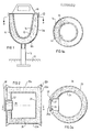
- the container illustrated in Figs. 1 and 1a is particularly useful as a rubbish bin for receiving rubbish at public locations and to provide some protection in case an explosive article is placed into it. It includes an outer high-strength housing 10 supported by a vertical leg 11 embedded in concrete 12.
- the high-strength outer housing 10 includes a cylindrical side wall 10a, a semi-spherical bottom wall 10b, and an open top which is closed by a removable cover 13.
- a rubbish basket 15 is supported on the inner liner 14 for receiving the rubbish introduced into the container, and is removable from the container in order to empty its contents.
- the inner liner 14 is spaced from the outer high-strength housing 10. This space is occupied by the inner compressible layer 16 described earlier which is effective, to space the article placed within basket 15 from the outer housing 10, to absorb energy of the blast before transmitted to the outer housing 10 should the article explode, to distribute the blast forces over a larger surface area of the outer housing 10, and to impart resistance to the penetration of fragments to the outer housing 10.
- the outer housing 10 may be of steel plate 5 mm in thickness having a height of 60 cm and a diameter of 50 cm; the inner liner 14 may be of steel of 2 mm thickness; the removable rubbish basket 15 may be of a plastic material; the inner compressible layer 16 may be a mixture of vermiculite and plaster or cement in which the vermiculite is present in the ratio of 6:1 by volume of the plaster, the mixture including 10% water by volume of the mix; and the thickness of the inner compressible layer 16 may be about 8 cm.
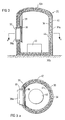
- Figs. 2 and 2a illustrate another type of blast-resistant container particularly useful for transporting a bomb, or an article that may be a bomb, to a location for detonation.
- the blast-resistant container illustrated in Figs. 2 and 2a also includes an outer high-strength housing 20, an inner liner 24 spaced from the inner face of the outer housing, and an inner compressible layer 26 of particulate material in a binder, similar to layer 16 in Figs. 1 and 1a.
- the outer housing 20 in the container of Figs. 2 and 2a is also of cylindrical construction, including a cylindrical side wall 20a, but is closed at its bottom by a flat bottom wall 20b, and at its top by a flat top wall 20c.
- An opening 27 is formed in its side wall 20a, which opening is closed by a blast-resistant door 28 having an externally-projecting handle 28a for moving the door along rail 29 either to a lower position (illustrated in Figs. 2, 2a) closing opening 27, or to a raised open position to permit access into the interior of the container.
- the cylindrical side wall 20a of the outer housing 20 may be of a diameter of 60 cm, a length of 80 cm, and a thickness of 10 mm; the bottom and top walls 20b and 20c may be of steel having a thickness of 14 mm; and the inner compressible layer 26 may have a thickness of 15 cm.
- the latter layer is preferably a mixture of vermiculite particles in a plaster binder as described above, but may also be in another binder, such as a cement binder.
- the blast-resistant container illustrated in Figs. 3 and 3a is intended to be used for detonating the bomb within the container itself.
- the container illustrated in Figs. 3 and 3a comprises an outer high-strength housing 30, and an inner compressible layer 36.
- the outer housing 30 in the container of Figs. 3 and 3a is also of cylindrical construction, including a cylindrical side wall 30a, but in this case it includes a flat bottom wall 30b and a semi-spherical top wall 30c.
- its side wall 30a is formed with an opening 37 closable by a blast- resistant and fragment-resistant door 38 having an externally-projecting handle 38a to facilitate moving the door either to its lower closed position (illustrated in Figs. 3 and 3a) or to its raised upper position for providing access into the interior of the container.
- the blast-resistant door 38 is movable along rails 39 formed in the inner face of the outer housing 30, but may be hingedly mounted.
- the container is provided with a table 40 for receiving the suspected bomb. Since the bomb to be detonated, when placed on the table, would be quite remote from the layer of compressible material 36, it has been found that the construction of Figs. 3, 3a does not require an inner liner, comparable to liner 14 and 24 in the first two described embodiments, but such a liner may nevertheless be provided as shown at 44.
- the inner compressible layer 36 in the container of Figs. 3 and 3a is preferably of the same vermiculite-plaster mixture used in the previously-described embodiments.
- the container of Figs. 3 and 3a further includes a wire mesh 42 embedded in the inner compressible layer 36. Mesh 42 provides additional absorption of the blast energy before transmitted to the outer housing 30.
- the outer housing 30 may have a diameter of 240 cm, a height of 300 cm, and may be of steel having a thickness of 14 mm; and the inner compressible layer may be of the vermiculite-plaster or vermiculite-cement mixture described above and having a thickness of 10 cm.
Abstract
Description
- The present invention relates to blast-resistant containers, and particularly to such containers for receiving an explosive or explosive-suspect article, such as a hidden bomb, for preventing or minimizing damage in the event the article explodes.
- Blast-resistant containers are now widely used for holding an explosive, or an explosive-suspect article, in order to either transport the article to a place where it can be safely detonated, or to permit its safe detonation within the container itself. The known blast-resistant containers presently in use are generally of very thick, heavy and bulky construction in order to be able to withstand the blast should the article placed within it explode.
- An object of the present invention is to provide a blast-resistant container which is of simpler, lighter and less bulky construction than the blast-resistant containers heretofore used.
- According to the present invention, there is provided a blast-resistant container for receiving an explosive or explosive-suspect article, comprising: a high-strength outer housing; characterized in that said housing includes an inner compressible layer of a mixture including vermiculite in a binder effective to space the article from the outer housing, to absorb energy of the blast before transmitted to the outer housing, to distribute the blast forces over a larger surface area of the outer housing, and to impart resistance to the penetration of fragments to the outer housing.
- Vermiculite is a micaceous hydrated silicate related to the chlorites and is normally used as heat insulation and/or for starting plant seeds and cuttings. Good results have been obtained when the vermiculite in the inner compressible layer of the present invention has an average small-dimension particle size of from 5 to 10 mm, and wherein the binder is plaster, or cement.
- A compressible layer including vermiculite, plaster or cement, and water, has been found to be particularly effective wherein the vermiculite is present from 2:1 to 10:1 parts by volume. Decreasing the quantity of the vermiculite to a ratio of less than 2:1 produces high resistance to penetration of fragments but low absorption of the energy of the blast before it is transmitted to the outer housing; whereas increasing the ratio of the vermiculite over 10:1 produces high energy absorption but very little penetration resistance of the fragments. Best results have been obtained when the inner compressible layer was a mixture of about 6:1 of vermiculite and plaster or cement plus a quantity of water equal to about 10% in volume of the total mix.
- Three embodiments of the invention are described below for purposes of example. In one described embodiment, the outer housing is open at the top and includes a removable cover closing its open top. This embodiment is particularly useful as a trash bin to be located in public places to provide some degree of protection to the public in case an explosive device is inserted into it. In two further described embodiments, the outer housing is formed with an opening in the side and includes a door which is movable to either an open position or to a closed position with respect to the side opening. Such a container construction is more particularly useful to hold an explosive-suspect article while being transported to a safe place for detonation, or for detonation within the container.
- Further features and advantages of the invention will be apparent from the description below.
- The invention is herein described, by way of example only, with reference to the accompanying drawings, wherein:
- Fig. 1 is a vertical sectional view illustrating one form of blast-resistant container constructed in accordance with the present invention, Fig. 1a being a horizontal sectional view along line a--a of Fig. 1;
- Fig. 2 is a vertical sectional view illustrating a second form of blast-resistant container constructed in accordance with the present invention, Fig. 2a being a horizontal sectional view along line a--a of Fig. 2; and
- Fig. 3 is a vertical sectional view of a third form of blast-resistant container constructed in accordance with the present invention, Fig. 3a being a horizontal sectional view along line a--a of Fig. 3.
- The container illustrated in Figs. 1 and 1a is particularly useful as a rubbish bin for receiving rubbish at public locations and to provide some protection in case an explosive article is placed into it. It includes an outer high-
strength housing 10 supported by avertical leg 11 embedded inconcrete 12. The high-strengthouter housing 10 includes acylindrical side wall 10a, asemi-spherical bottom wall 10b, and an open top which is closed by aremovable cover 13. - Disposed within the
outer housing 10 is aninner liner 14 of dished construction and spaced from theouter housing 10. Arubbish basket 15 is supported on theinner liner 14 for receiving the rubbish introduced into the container, and is removable from the container in order to empty its contents. - As clearly seen in Figs. 1 and 1a, the
inner liner 14 is spaced from the outer high-strength housing 10. This space is occupied by the innercompressible layer 16 described earlier which is effective, to space the article placed withinbasket 15 from theouter housing 10, to absorb energy of the blast before transmitted to theouter housing 10 should the article explode, to distribute the blast forces over a larger surface area of theouter housing 10, and to impart resistance to the penetration of fragments to theouter housing 10. - As one example, the
outer housing 10 may be of steel plate 5 mm in thickness having a height of 60 cm and a diameter of 50 cm; theinner liner 14 may be of steel of 2 mm thickness; theremovable rubbish basket 15 may be of a plastic material; the innercompressible layer 16 may be a mixture of vermiculite and plaster or cement in which the vermiculite is present in the ratio of 6:1 by volume of the plaster, the mixture including 10% water by volume of the mix; and the thickness of the innercompressible layer 16 may be about 8 cm. - Figs. 2 and 2a illustrate another type of blast-resistant container particularly useful for transporting a bomb, or an article that may be a bomb, to a location for detonation. The blast-resistant container illustrated in Figs. 2 and 2a also includes an outer high-
strength housing 20, aninner liner 24 spaced from the inner face of the outer housing, and an innercompressible layer 26 of particulate material in a binder, similar tolayer 16 in Figs. 1 and 1a. - The
outer housing 20 in the container of Figs. 2 and 2a is also of cylindrical construction, including acylindrical side wall 20a, but is closed at its bottom by aflat bottom wall 20b, and at its top by aflat top wall 20c. Anopening 27 is formed in itsside wall 20a, which opening is closed by a blast-resistant door 28 having an externally-projectinghandle 28a for moving the door alongrail 29 either to a lower position (illustrated in Figs. 2, 2a)closing opening 27, or to a raised open position to permit access into the interior of the container. - As one example, the
cylindrical side wall 20a of theouter housing 20 may be of a diameter of 60 cm, a length of 80 cm, and a thickness of 10 mm; the bottom andtop walls compressible layer 26 may have a thickness of 15 cm. The latter layer is preferably a mixture of vermiculite particles in a plaster binder as described above, but may also be in another binder, such as a cement binder. - The blast-resistant container illustrated in Figs. 3 and 3a is intended to be used for detonating the bomb within the container itself. Thus, the container illustrated in Figs. 3 and 3a comprises an outer high-
strength housing 30, and an innercompressible layer 36. Theouter housing 30 in the container of Figs. 3 and 3a is also of cylindrical construction, including acylindrical side wall 30a, but in this case it includes aflat bottom wall 30b and asemi-spherical top wall 30c. For providing access into the interior of the container, itsside wall 30a is formed with an opening 37 closable by a blast- resistant and fragment-resistant door 38 having an externally-projectinghandle 38a to facilitate moving the door either to its lower closed position (illustrated in Figs. 3 and 3a) or to its raised upper position for providing access into the interior of the container. In this case, the blast-resistant door 38 is movable alongrails 39 formed in the inner face of theouter housing 30, but may be hingedly mounted. - In addition, the container is provided with a table 40 for receiving the suspected bomb. Since the bomb to be detonated, when placed on the table, would be quite remote from the layer of
compressible material 36, it has been found that the construction of Figs. 3, 3a does not require an inner liner, comparable toliner - The inner
compressible layer 36 in the container of Figs. 3 and 3a is preferably of the same vermiculite-plaster mixture used in the previously-described embodiments. However, the container of Figs. 3 and 3a further includes awire mesh 42 embedded in the innercompressible layer 36.Mesh 42 provides additional absorption of the blast energy before transmitted to theouter housing 30. - As one example, the
outer housing 30 may have a diameter of 240 cm, a height of 300 cm, and may be of steel having a thickness of 14 mm; and the inner compressible layer may be of the vermiculite-plaster or vermiculite-cement mixture described above and having a thickness of 10 cm.
Claims (10)
Priority Applications (1)
| Application Number | Priority Date | Filing Date | Title |
|---|---|---|---|
| AT88630030T ATE88266T1 (en) | 1987-07-16 | 1988-02-18 | EXPLOSION PROOF CONTAINER. |
Applications Claiming Priority (2)
| Application Number | Priority Date | Filing Date | Title |
|---|---|---|---|
| IL83209A IL83209A (en) | 1987-07-16 | 1987-07-16 | Blast-resistant container |
| IL83209 | 1987-07-16 |
Publications (3)
| Publication Number | Publication Date |
|---|---|
| EP0299902A2 true EP0299902A2 (en) | 1989-01-18 |
| EP0299902A3 EP0299902A3 (en) | 1990-03-21 |
| EP0299902B1 EP0299902B1 (en) | 1993-04-14 |
Family
ID=11057981
Family Applications (1)
| Application Number | Title | Priority Date | Filing Date |
|---|---|---|---|
| EP88630030A Expired - Lifetime EP0299902B1 (en) | 1987-07-16 | 1988-02-18 | Blast-resistant container |
Country Status (8)
| Country | Link |
|---|---|
| US (1) | US4889258A (en) |
| EP (1) | EP0299902B1 (en) |
| JP (1) | JPS6438600A (en) |
| AT (1) | ATE88266T1 (en) |
| CA (1) | CA1308075C (en) |
| DE (1) | DE3880224T2 (en) |
| ES (1) | ES2039689T3 (en) |
| IL (1) | IL83209A (en) |
Cited By (10)
| Publication number | Priority date | Publication date | Assignee | Title |
|---|---|---|---|---|
| GB2262798A (en) * | 1991-12-24 | 1993-06-30 | British Aerospace | An aircraft cargo container |
| GB2279231A (en) * | 1993-06-26 | 1995-01-04 | Glasdon Ltd | Bomb-resistant container |
| EP1013568A1 (en) | 1998-12-24 | 2000-06-28 | SNGS (société anonyme) | Anti-assault device for containers |
| WO2004065892A1 (en) * | 2003-01-17 | 2004-08-05 | Projectile Limited | Blast attenuating, blast-directing and extinguishing apparatus |
| EP1587746A2 (en) * | 2002-11-07 | 2005-10-26 | Fannon, David J. | Bomb proof garbage container |
| WO2005038388A3 (en) * | 2003-10-18 | 2007-03-29 | Stephan Hauser | Mobile munition container and mobile bunker or shelter and method and use of a reinforcing mat for producing said containers and bunkers (shelters) |
| EP1899674A2 (en) * | 2005-06-28 | 2008-03-19 | K.P.S. - Karil Protective Systems Ltd. | Safe inspection system and kit |
| GB2488347A (en) * | 2011-02-23 | 2012-08-29 | Renew Pod Ltd | U-shaped space in the wall of a bin for blast absorbent gel |
| GB2544343A (en) * | 2015-11-13 | 2017-05-17 | Philbin Products Ltd | Receptacle and its method of manufacture |
| CN108267054A (en) * | 2018-03-13 | 2018-07-10 | 中国工程物理研究院化工材料研究所 | A kind of excellent explosive container of dynamic sealing performance |
Families Citing this family (30)
| Publication number | Priority date | Publication date | Assignee | Title |
|---|---|---|---|---|
| US5267665A (en) * | 1991-09-20 | 1993-12-07 | Sri International | Hardened luggage container |
| WO1995008749A1 (en) * | 1993-09-24 | 1995-03-30 | John Humphries Parkes | A blast and splinter proof screening device and its method of use |
| US7185778B1 (en) | 1995-09-25 | 2007-03-06 | Allied-Signal Inc. | Barrier units and articles made therefrom |
| US6341708B1 (en) | 1995-09-25 | 2002-01-29 | Alliedsignal Inc. | Blast resistant and blast directing assemblies |
| US6991124B1 (en) | 1995-09-25 | 2006-01-31 | Alliedsignal Inc. | Blast resistant and blast directing containers and methods of making |
| US5684264A (en) * | 1995-10-26 | 1997-11-04 | Cassells; James R. | Ballistic containment device |
| IL136683A0 (en) * | 1997-12-12 | 2001-06-14 | Ca Solicitor General | Apparatus and method for blast supression |
| US6196107B1 (en) | 1998-04-10 | 2001-03-06 | The United States Of America As Represented By The Secretary Of The Navy | Explosive containment device |
| US7014059B2 (en) * | 2002-05-17 | 2006-03-21 | Master Lite Security Products, Inc. | Explosion resistant waste container |
| US20050252915A1 (en) * | 2002-05-17 | 2005-11-17 | Mirror Lite | Explosion resistant waste container |
| US6644165B1 (en) | 2002-05-23 | 2003-11-11 | Nabco, Inc. | Explosion containment vessel |
| CN100380092C (en) * | 2002-12-31 | 2008-04-09 | 中国民用航空总局航空安全技术中心 | Antiexplosion box used in civil aircraft passenger cabinet |
| CA2437144A1 (en) * | 2003-08-08 | 2005-02-08 | Bosik Security Containment Systems Limited | Blast-resistant panels and containers |
| WO2005015119A1 (en) * | 2003-08-08 | 2005-02-17 | Vanguard Protective Technologies Inc. | Blast-resistant panels and containers |
| US7506568B2 (en) * | 2003-11-05 | 2009-03-24 | Nabco, Inc. | Sealed upscale total containment vessel |
| US20070029321A1 (en) | 2005-08-02 | 2007-02-08 | Honeywell International Inc. | Technology for blast containers |
| EP1920212A4 (en) * | 2005-09-01 | 2008-10-01 | Vulcan Lead Inc | Shielded device containment vessel |
| CA2545303A1 (en) * | 2005-09-06 | 2007-03-06 | Guy Gettle | Case for small explosive device |
| US7748307B2 (en) | 2006-08-04 | 2010-07-06 | Gerald Hallissy | Shielding for structural support elements |
| DE202007003938U1 (en) * | 2007-03-17 | 2007-06-06 | Burg-Wächter Kg | Container, especially a safe or valuables cabinet, for storing objects to be protected against unauthorized access, has housing with storage space and an opening closable by door and/or flap |
| US7926407B1 (en) * | 2007-11-16 | 2011-04-19 | Gerald Hallissy | Armor shielding |
| JP5207362B2 (en) * | 2008-04-14 | 2013-06-12 | 独立行政法人産業技術総合研究所 | Explosive storage container |
| KR20120014165A (en) | 2009-04-23 | 2012-02-16 | 디에스엠 아이피 어셋츠 비.브이. | Compressed sheet |
| US8413564B1 (en) * | 2009-09-29 | 2013-04-09 | The United States Of America As Represented By The Secretary Of The Army | Portable vented suppressive shield for protective tactical emplacement over suspected explosive devices |
| US8443922B2 (en) * | 2009-10-07 | 2013-05-21 | The Boeing Company | Containment device and method for containing energy storage devices |
| US10344973B1 (en) * | 2017-11-17 | 2019-07-09 | The United States Of America As Represented By The Secretary Of The Navy | Apparatus for incinerating explosive devices and biological agents |
| US10451394B2 (en) | 2018-03-09 | 2019-10-22 | The Boeing Company | Containment vessel and method for stowing a high energy density device |
| CN108307865A (en) * | 2018-03-16 | 2018-07-24 | 中国林业科学研究院沙漠林业实验中心 | Ecological environment-friendly type flowerpot for handling rubbish |
| US10914564B1 (en) * | 2020-07-30 | 2021-02-09 | The United States Of America As Represented By The Secretary Of The Navy | Blast containment system for trash cans |
| CN114234753A (en) * | 2021-11-30 | 2022-03-25 | 三门峡市天康成套设备有限责任公司 | Rigid-flexible combined explosion-proof structure and preparation method thereof |
Citations (3)
| Publication number | Priority date | Publication date | Assignee | Title |
|---|---|---|---|---|
| US3804017A (en) * | 1972-03-30 | 1974-04-16 | Atomic Energy Commission | Method for mitigating blast and shock transmission within a confined volume |
| US4027601A (en) * | 1976-04-19 | 1977-06-07 | The United States Of America As Represented By The Secretary Of The Army | Container for explosive device |
| US4055247A (en) * | 1976-10-22 | 1977-10-25 | The United States Of America As Represented By The United States Energy Research And Development Administration | Explosion containment device |
Family Cites Families (6)
| Publication number | Priority date | Publication date | Assignee | Title |
|---|---|---|---|---|
| US2780350A (en) * | 1951-12-11 | 1957-02-05 | Lockheed Aircraft Corp | Package with cellular plastic packaging means |
| US3145837A (en) * | 1962-12-31 | 1964-08-25 | Chicago Curled Hair Company | Shock-absorbing device |
| US3481504A (en) * | 1968-07-05 | 1969-12-02 | Pittsburgh Des Moines Steel | Liquid storage container |
| US3739731A (en) * | 1970-08-05 | 1973-06-19 | P Tabor | Open enclosure for explosive charge |
| US3820435A (en) * | 1972-05-11 | 1974-06-28 | Atomic Energy Commission | Confinement system for high explosive events |
| US4628819A (en) * | 1985-08-16 | 1986-12-16 | The United States Of America As Represented By The Secretary Of The Navy | Disintegrating tamper mass |
-
1987
- 1987-07-16 IL IL83209A patent/IL83209A/en not_active IP Right Cessation
-
1988
- 1988-02-18 EP EP88630030A patent/EP0299902B1/en not_active Expired - Lifetime
- 1988-02-18 AT AT88630030T patent/ATE88266T1/en not_active IP Right Cessation
- 1988-02-18 DE DE8888630030T patent/DE3880224T2/en not_active Expired - Lifetime
- 1988-02-18 ES ES198888630030T patent/ES2039689T3/en not_active Expired - Lifetime
- 1988-06-30 US US07/213,569 patent/US4889258A/en not_active Expired - Lifetime
- 1988-07-15 JP JP63176888A patent/JPS6438600A/en active Pending
- 1988-07-15 CA CA000572228A patent/CA1308075C/en not_active Expired - Lifetime
Patent Citations (3)
| Publication number | Priority date | Publication date | Assignee | Title |
|---|---|---|---|---|
| US3804017A (en) * | 1972-03-30 | 1974-04-16 | Atomic Energy Commission | Method for mitigating blast and shock transmission within a confined volume |
| US4027601A (en) * | 1976-04-19 | 1977-06-07 | The United States Of America As Represented By The Secretary Of The Army | Container for explosive device |
| US4055247A (en) * | 1976-10-22 | 1977-10-25 | The United States Of America As Represented By The United States Energy Research And Development Administration | Explosion containment device |
Cited By (18)
| Publication number | Priority date | Publication date | Assignee | Title |
|---|---|---|---|---|
| GB2262798A (en) * | 1991-12-24 | 1993-06-30 | British Aerospace | An aircraft cargo container |
| GB2279231A (en) * | 1993-06-26 | 1995-01-04 | Glasdon Ltd | Bomb-resistant container |
| GB2279231B (en) * | 1993-06-26 | 1997-07-02 | Glasdon Ltd | Bomb-resistant container |
| EP1013568A1 (en) | 1998-12-24 | 2000-06-28 | SNGS (société anonyme) | Anti-assault device for containers |
| FR2787769A1 (en) * | 1998-12-24 | 2000-06-30 | Sngs | ANTI-ATTACK DEVICE FOR CONTAINERS |
| EP1587746A2 (en) * | 2002-11-07 | 2005-10-26 | Fannon, David J. | Bomb proof garbage container |
| EP1587746A4 (en) * | 2002-11-07 | 2006-03-29 | Fannon David J | Bomb proof garbage container |
| CN1759294B (en) * | 2003-01-17 | 2011-01-12 | 志远有限公司 | Blast attenuating, blast-directing and extinguishing apparatus |
| WO2004065892A1 (en) * | 2003-01-17 | 2004-08-05 | Projectile Limited | Blast attenuating, blast-directing and extinguishing apparatus |
| WO2005038388A3 (en) * | 2003-10-18 | 2007-03-29 | Stephan Hauser | Mobile munition container and mobile bunker or shelter and method and use of a reinforcing mat for producing said containers and bunkers (shelters) |
| EP1899674A4 (en) * | 2005-06-28 | 2011-01-05 | K P S Karil Protective Systems Ltd | Safe inspection system and kit |
| EP1899674A2 (en) * | 2005-06-28 | 2008-03-19 | K.P.S. - Karil Protective Systems Ltd. | Safe inspection system and kit |
| US7966919B2 (en) | 2005-06-28 | 2011-06-28 | K.P.S.—Karil Protective Systems Ltd. | Safe inspection system and kit |
| GB2488347A (en) * | 2011-02-23 | 2012-08-29 | Renew Pod Ltd | U-shaped space in the wall of a bin for blast absorbent gel |
| GB2544343A (en) * | 2015-11-13 | 2017-05-17 | Philbin Products Ltd | Receptacle and its method of manufacture |
| GB2544343B (en) * | 2015-11-13 | 2018-01-17 | Philbin Products Ltd | Receptacle and its method of manufacture |
| CN108267054A (en) * | 2018-03-13 | 2018-07-10 | 中国工程物理研究院化工材料研究所 | A kind of excellent explosive container of dynamic sealing performance |
| CN108267054B (en) * | 2018-03-13 | 2023-11-10 | 中国工程物理研究院化工材料研究所 | Explosion container with excellent dynamic sealing performance |
Also Published As
| Publication number | Publication date |
|---|---|
| IL83209A0 (en) | 1988-02-29 |
| ATE88266T1 (en) | 1993-04-15 |
| IL83209A (en) | 1991-01-31 |
| US4889258A (en) | 1989-12-26 |
| JPS6438600A (en) | 1989-02-08 |
| CA1308075C (en) | 1992-09-29 |
| DE3880224D1 (en) | 1993-05-19 |
| ES2039689T3 (en) | 1993-10-01 |
| DE3880224T2 (en) | 1993-08-12 |
| EP0299902A3 (en) | 1990-03-21 |
| EP0299902B1 (en) | 1993-04-14 |
Similar Documents
| Publication | Publication Date | Title |
|---|---|---|
| US4889258A (en) | Blast-resistant container | |
| AU771845B2 (en) | Method and apparatus for containing and suppressing explosive detonations | |
| US5158173A (en) | Weapons storage container to prevent sympathetic detonation of adjacent weapons | |
| AU588226B2 (en) | Containers | |
| ES2076741T3 (en) | PORTABLE CONTAINER WITH AUTOMATIC DISCHARGE CAPACITY. | |
| SE8405336D0 (en) | MOBILE HOUSE CONSTRUCTION | |
| EP1360454A1 (en) | Blast attenuation container | |
| US5527983A (en) | Method for the destruction of noxious materials | |
| MXPA02009129A (en) | Silo and or filter device for inflammable dry bulk freight. | |
| US5160468A (en) | Method for preparing a storage container for explosive rounds | |
| TW259727B (en) | Device for storage and disposal of waste material | |
| GB2355057A (en) | Bomb containment device | |
| SU1268476A1 (en) | Arrangement for collecting and transporting food waste | |
| FI65330C (en) | BEHAOLLARE FOER SPRAENGNINGSTILLBEHOER | |
| CN211418320U (en) | Storehouse is stored to safety of convenient show | |
| US2629349A (en) | Underground fireproof vault | |
| RU29048U1 (en) | Explosion proof urn | |
| RU2206865C2 (en) | Method for ensuring of group explosion proofness | |
| ES2157141A1 (en) | Improved protection structure applicable to the protection, scrimping, and storage of general waste containers | |
| AU665143B2 (en) | Storage container for hazardous substance tanks | |
| PL161744B1 (en) | Method of safely disposing sulfurized wastes | |
| TH9011EX (en) | Handling, put into tower kiln, especially metal smelting furnace | |
| HU9201653D0 (en) | Underground storage device mainly for storing inflammable and explosive materials or similar products | |
| UA801U (en) | Container for collection of waste |
Legal Events
| Date | Code | Title | Description |
|---|---|---|---|
| PUAI | Public reference made under article 153(3) epc to a published international application that has entered the european phase |
Free format text: ORIGINAL CODE: 0009012 |
|
| AK | Designated contracting states |
Kind code of ref document: A2 Designated state(s): AT BE CH DE ES FR GB GR IT LI NL SE |
|
| PUAL | Search report despatched |
Free format text: ORIGINAL CODE: 0009013 |
|
| AK | Designated contracting states |
Kind code of ref document: A3 Designated state(s): AT BE CH DE ES FR GB GR IT LI NL SE |
|
| 17P | Request for examination filed |
Effective date: 19900601 |
|
| 17Q | First examination report despatched |
Effective date: 19910909 |
|
| GRAA | (expected) grant |
Free format text: ORIGINAL CODE: 0009210 |
|
| AK | Designated contracting states |
Kind code of ref document: B1 Designated state(s): AT BE CH DE ES FR GB GR IT LI NL SE |
|
| PG25 | Lapsed in a contracting state [announced via postgrant information from national office to epo] |
Ref country code: SE Effective date: 19930414 Ref country code: AT Effective date: 19930414 |
|
| REF | Corresponds to: |
Ref document number: 88266 Country of ref document: AT Date of ref document: 19930415 Kind code of ref document: T |
|
| ET | Fr: translation filed | ||
| REF | Corresponds to: |
Ref document number: 3880224 Country of ref document: DE Date of ref document: 19930519 |
|
| ITF | It: translation for a ep patent filed |
Owner name: UFFICIO BREVETTI RICCARDI & C. |
|
| K2C3 | Correction of patent specification (complete document) published |
Effective date: 19930414 |
|
| REG | Reference to a national code |
Ref country code: GR Ref legal event code: FG4A Free format text: 3008460 |
|
| REG | Reference to a national code |
Ref country code: ES Ref legal event code: FG2A Ref document number: 2039689 Country of ref document: ES Kind code of ref document: T3 |
|
| PLBE | No opposition filed within time limit |
Free format text: ORIGINAL CODE: 0009261 |
|
| STAA | Information on the status of an ep patent application or granted ep patent |
Free format text: STATUS: NO OPPOSITION FILED WITHIN TIME LIMIT |
|
| 26N | No opposition filed | ||
| REG | Reference to a national code |
Ref country code: GB Ref legal event code: IF02 |
|
| PGFP | Annual fee paid to national office [announced via postgrant information from national office to epo] |
Ref country code: DE Payment date: 20070216 Year of fee payment: 20 Ref country code: GB Payment date: 20070216 Year of fee payment: 20 |
|
| PGFP | Annual fee paid to national office [announced via postgrant information from national office to epo] |
Ref country code: CH Payment date: 20070221 Year of fee payment: 20 |
|
| PGFP | Annual fee paid to national office [announced via postgrant information from national office to epo] |
Ref country code: NL Payment date: 20070222 Year of fee payment: 20 |
|
| PGFP | Annual fee paid to national office [announced via postgrant information from national office to epo] |
Ref country code: ES Payment date: 20070227 Year of fee payment: 20 |
|
| PGFP | Annual fee paid to national office [announced via postgrant information from national office to epo] |
Ref country code: BE Payment date: 20070308 Year of fee payment: 20 |
|
| BE20 | Be: patent expired |
Owner name: *KOOR METALS LTD Effective date: 20080218 |
|
| REG | Reference to a national code |
Ref country code: GB Ref legal event code: PE20 |
|
| PGFP | Annual fee paid to national office [announced via postgrant information from national office to epo] |
Ref country code: GR Payment date: 20070228 Year of fee payment: 20 |
|
| REG | Reference to a national code |
Ref country code: CH Ref legal event code: PL |
|
| NLV7 | Nl: ceased due to reaching the maximum lifetime of a patent |
Effective date: 20080218 |
|
| PG25 | Lapsed in a contracting state [announced via postgrant information from national office to epo] |
Ref country code: NL Free format text: LAPSE BECAUSE OF EXPIRATION OF PROTECTION Effective date: 20080218 |
|
| PGFP | Annual fee paid to national office [announced via postgrant information from national office to epo] |
Ref country code: FR Payment date: 20070220 Year of fee payment: 20 |
|
| REG | Reference to a national code |
Ref country code: ES Ref legal event code: FD2A Effective date: 20080219 |
|
| PG25 | Lapsed in a contracting state [announced via postgrant information from national office to epo] |
Ref country code: GB Free format text: LAPSE BECAUSE OF EXPIRATION OF PROTECTION Effective date: 20080217 |
|
| PGFP | Annual fee paid to national office [announced via postgrant information from national office to epo] |
Ref country code: IT Payment date: 20071228 Year of fee payment: 20 |
|
| PG25 | Lapsed in a contracting state [announced via postgrant information from national office to epo] |
Ref country code: ES Free format text: LAPSE BECAUSE OF EXPIRATION OF PROTECTION Effective date: 20080219 |