EP0300633A2 - Time base corrector - Google Patents
Time base corrector Download PDFInfo
- Publication number
- EP0300633A2 EP0300633A2 EP88306100A EP88306100A EP0300633A2 EP 0300633 A2 EP0300633 A2 EP 0300633A2 EP 88306100 A EP88306100 A EP 88306100A EP 88306100 A EP88306100 A EP 88306100A EP 0300633 A2 EP0300633 A2 EP 0300633A2
- Authority
- EP
- European Patent Office
- Prior art keywords
- signal
- time base
- resampling
- analog
- amplitude values
- Prior art date
- Legal status (The legal status is an assumption and is not a legal conclusion. Google has not performed a legal analysis and makes no representation as to the accuracy of the status listed.)
- Granted
Links
Images


Classifications
-
- H—ELECTRICITY
- H04—ELECTRIC COMMUNICATION TECHNIQUE
- H04N—PICTORIAL COMMUNICATION, e.g. TELEVISION
- H04N5/00—Details of television systems
- H04N5/76—Television signal recording
- H04N5/91—Television signal processing therefor
- H04N5/93—Regeneration of the television signal or of selected parts thereof
- H04N5/95—Time-base error compensation
Definitions
- the present invention relates to a time base corrector for correcting a time base error, or a time base instability, of a signal such as a video signal reproduced from a magnetic tape.
- time base correctors In video tape recorders used for broadcast, time base correctors have been widely used for correcting time base errors of reproduced video signals.
- U.S. Patent No. 3,931,638 discloses a time base corrector employing analog shift registers in which one register has samples of one video line signal clocked into at a rate corresponding to its time base instability, and the other register clocks out, at a uniform rate, analog signals of the previous line, and vice versa.
- Another type time base corrector employing variable delay lines is disclosed in an article "Overview of Time-Base Correction Techniques and Their Applications” by K. Sadashige, SMPTE Journal Vol. 85 October 1976, pp. 787-791.
- These time base correctors have generally known disadvantages due to the use of analog devices such as analog shift registers and variable delay lines.
- a reproduced analog video signal with a time base error is sampled and converted into a digital signal by an analog-to-digital (AD) converter responsive to a clock signal which is locked to the incomming reproduced analog video signal.
- the digital signal is stored into a memory.
- the temporarily stored digital signal is read out in response to another clock signal that has a fixed time base.
- the read-out digital signal is converted to an analog signal by a digital-to-analog (DA) converter.
- DA digital-to-analog
- Such conventional digital time base corrector have some problems.
- One problem is that it must be provided with analog components in the clock generator for generating the clock signal which is locked to the incomming reproduced analog video signal. Performance variations and temperature characteristics of the analog components will cause undesired variations of the generated clock signal, which badly affect the performances of the time base corrector.
- the analog components including capacitors and inductors cannot be mounted in an integrated circuit, it is difficult to reduce the cost of the time base corrector.
- Another problem is that, since the memory writing and reading operations are controlled by the respective two different clock signals, constructions of the memories and memory controller are complicated.
- the AD converter is driven by the time base fluctuated clock signal, the output of the AD converter cannot be used commonly in other digital processing systems.
- An object of the present invention is to provide a novel time base corrector which is accurate and stable in operation.
- Another object of the present invention is to provide a novel time base corrector which can be easily integrated in an integrated circuit to be low in cost.
- Still another object of the present invention is to provide a novel time base corrector which does not use such a clock signal that has time base fluctuation, but uses only a clock signal whose period is fixed.
- a time base corrector of the present invention comprises: a clock generator which generates a clock signal having a fixed period; an analog-to-digital converter driven by the clock signal for sampling amplitude values of an input analog signal at sampling points determined by the clock signal; a resampling position signal producing circuit for detecting a time base error of the input analog signal and producing from the detected time base error a resampling position signal indicative of a resampling point at which an amplitude value of the input analog signal which would be sampled at the sampling point if there were not the time base error is present; an adaptive interpolation filter for interpolating amplitude values at resampling points indicated by the resampling position signal using the sampled amplitude values and the resampling position signal, and outputting the interpolated amplitude values at the sampling timings given by the clock signal; and a digital-to-analog converter driven by the clock signal for converting the output interpolated amplitude values to an analog signal,
- the resampling position signal producing circuit may detect the time base error from either the output of the analog-to-digital converter or the output of the adaptive interpolation filter.
- FIG. 1 is a block diagram of the first preferred embodiment of the invention for correcting time base errors of a video signal 200 reproduced from a recording medium (not shown).
- a clock generator 107 comprising a crystal oscillator generates a clock signal 201 having a constant period T.
- the clock period T is equal to 1/L of a desired horizontal scanning period of the video signal.
- An analog-to-digital (AD) converter 103 samples amplitude values of the video signal 200 in response to the clock signal 201 to produce a digital video signal 202.
- AD analog-to-digital
- a resampling position signal producing (RPSP) circuit 102 detects the time base error of the digitized video signal 202 from a luminance synchronizing signal of the digitized video signal 202, and produces a resampling position signal 203 which represents a position of a resampling point relative to a sampling point of the AD converter, at which resampling point an amplitude value which would be sampled at the sampling point if there were no time base error is present.
- RPSP resampling position signal producing
- An adaptive interpolation filter 104 generates a digital signal 204 which represents amplitude values of the video signal 200 at respective resampling points indicated by the resampling position signal 203, by means of interpolation arithmetic using the digital signal 202 and the resampling position signal 203.
- a digital-to-analog (DA) converter 106 converts the digital signal 204 to an analog video signal 205, which is outputted from an output terminal 18.
- the output video signal 205 has no time base errors and its horizontal scanning period is L times the period of the clock signal 201.
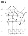
- FIG. 2 illustrates the principle of the time base error correction in this embodiment.
- (a) is a waveform of an original signal (before recording) without time base errors
- (d) shows the clock signal 201 whose period is T.
- FIG. 2 (b) is a waveform of the reproduced signal 200 with a time base error.
- the AD converter 103 in FIG. 1 samples amplitude values of the input signal 200 at sampling points 301-305 indicated by black dots in FIG. 2 (b).
- the adaptive interpolation filter 104 in FIG. 1 calculates amplitude values at resampling points 311-315 indicated by a square symbol ⁇ in FIG.
- FIG. 2 (c) which are locked to the time base of the input signal 200, and outputs the resampled data at timings given by the clock signal 201 as shown in FIG. 2 (c).
- the signal shown in FIG. 2 (c) is the time base error corrected signal, which is identical to the original signal shown in FIG. 2 (a).
- the resampling point signal 203 represents the resampling time ⁇ that is locked to the time base of the input video signal 200.
- the adaptive interpolation filter 104 generates v( ⁇ ) according to Eq. (4).
- lines except for the lines of the clock signal 201 represent digital signal lines each having a plurality of parallel bits.
- the recieved digital signal 202 at an input terminal 111 of the adaptive interpolation filter is fed to a shift register 112 comprising a plurality of serially connected delay circuits each being configured by a plurality of parallel D-flip- flops.
- each delay circuit delays a data inputted thereto for a time corresponding to one period of the clock signal 201.
- sequentially shifted sets of four successive sampled values 113 to 118 each being shifted by one clock from the previous set are fed to selecting circuit 119.
- the selecting circuit 119 selects one of the sets 113 to 118 according to a selecting signal 134 (which will be described later) and outputs the selected set as a data set 120.
- the resampling position signal 203 is received by a dividing circuit 133.
- the dividing circuit 133 produces the selecting signal 134 and a time indicating signal 132.
- the selecting signal 134 and the time indicating signal 132 will be described below with reference to FIG. 5.
- FIG. 5 shows a waveform of a part of the input video signal 202.
- Points 140 to 148 indicated by black dots are sampling points sampled by the AD converter 103 in FIG. 1 in response to the clock signal 201.
- Points 240 to 247 indicated by square symbols ⁇ are resampling points which would be sampled if there were no time base error and which are to be interpolated by the adaptive interpolation filter 104 in FIG. 1.
- the interpolated, or resampled, data are outputted at the timing synchronized with the clock signal 201 as indicated by white circles o in FIG. 5.
- the data set of four successive sampled values at the sampling points 142 to 145 is selected as the data set 120 in FIG. 4 by the selecting circuit 119 according to the selecting signal 134.
- the time indicating signal 132 in FIG. 4 represents the time shift ⁇ t within one period of the clock signal 201 as shown in FIG. 5.
- Predetermined upper bits of the resampling position signal 203 are used as the selecting signal 134, and the remaining lower bits are used as the time indicating signal 132.
- the time base error can be expressed as nT + ⁇ t, when n is an integer (either positive or negative) including 0, T is the period of the clock signal 201, and ⁇ t is a time shift within one period of the clock signal 201.
- the upper bits of the resampling position signal represent nT and the lower bits represent ⁇ t.
- the four sampled values of the data set 120 are fed to multipliers 121 to 124 respectively.
- the time indicating signal 132 is fed as an address to a read-only-memory (ROM) 131 so that coefficient data 127 to 130 are read from the ROM 131, and led to the multipliers 121 to 124 respectively.
- the multipliers 121-124 multiply the four sampled values of the data set 120 by the coefficient data 127-130, respectively.
- An adder 125 adds the outputs of the multipliers 121 to 124 to obtain the signal 204 which represents v( ⁇ ) in Eq. (4) and which is the time base error corrected signal.
- the signal 204 is outputted from an output terminal 126.
- N and M should be determined so that the error in computation according to Eq. (4) is small enough.
- the number of stages of the shift register 112 should be determined according to the range of time base correction to be needed.
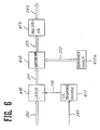
- FIG. 6 is a block diagram of an example of the resampling position signal producing circuit 102
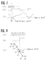
- FIG. 7 shows waveforms at some points in the resampling position signal producing circuit in FIG. 6,
- FIG. 8 is an enlarged detail during the period A in FIG. 7.
- a frequency divider 411 divides the frequency of the clock signal 201 by L to produce a divided clock signal 210 whose frequency is 1/L times the frequency of the clock signal 201. So, the period of the divided clock signal 210 is equal to the desired horizontal scanning period.
- the relationship among the clock signal 201, the divided clock signal 210 and the input video signal 200 is illustrated in FIG. 7.
- FIG. 7 shows the clock signal 201
- (b) shows the divided clock signal 210
- (c) shows the input video signal 200 with a reference level represented by a reference signal 212 in FIG. 6.
- the leading edge of each pulse of the divided clock signal 210 occurs during the transition period of each horizontal synchronizing signal of the input video signal.
- a latch circuit 410 latches the digitized video signal 202 in response to the divided clock signal 210 to obtain a latched signal 211.
- the amplitude value at a sampling point 154 is latched among values at sampling points 151 to 156.
- a subtractor 412 in FIG. 6 produces an amplitude difference, as a signal 213, between the latched signal 211 and the reference signal 212 which is produced by a reference source 412a.
- the reference level indicates that a point 160 is a desired sampling point which should be sampled by the divided clock signal 210 shown in FIG. 8 (b).
- the signal 213 in FIG. 6 represents an amplitude difference shown as 161 in FIG. 8 (c).
- a time difference 162 between the latched point 154 and the desired point 160 is almost in proportion to the amplitude difference 161. Therefore, the signal 213 in FIG. 6 can be regarded as a signal representing the time difference 162.
- the signal 213 is multiplied by a predetermined coefficient at a multiplier 413 to become the resampling position signal 214.
- the embodiment in FIG. 1 can correct time base errors by implementing digital signal processing without any analog signal processing. Therefore it is not affected by variations of physical quantities of and the temperature characteristics of analog components. Furthermore, since the embodiment does not use any analog components, it is able to fabricate the whole circuit in an integrated circuit thereby to reduce cost. Still more, since the embodiment does not use any clock signal having time base fluctuations, it is easy to join the time base corrector with other digital signal processing systems.
- One more feature of the present embodiment is that the time base errors are corrected by means of feedforward control, which can correct rapid time base fluctuations.
- the interpolation function s(t) is obtained based on Eq. (3) which is the impulse response of an ideal low-pass filter. But, it may be possible to use as s(t) an impulse response of a cosine role-off filter whose frequency response is shown in FIG. 9. In such case, the function s(t) is obtained by the following equation (5): Using this s(t), the number of the sampled values for producing v(t) interpolated with an adequately small error (namely, N-M+1 in Eq. (4)) can be drastically decreased. Therefore the adaptive interpolation filter can be constructed in an smaller circuit scale.
- the adaptive interpolation filter may use random-access-memories (RAMs) for delaying the input signal and an address control circuit for selecting the data set.
- RAMs random-access-memories
- FIG. 10 is a block diagram of the second preferred embodiment of the invention.
- the same numbers are assigned to the blocks having the same functions as those of the first embodiment in FIG. 1.
- a resampling position signal producing (RPSP) circuit 109 detects the time base error of the digital signal 204 from the luminance synchronizing signal of the digital signal 204 and feeds the resampling position signal 203 back to the adaptive interpolation filter 104.
- RPSP resampling position signal producing
- FIG. 11 is a block diagram of a first example of the resampling position producing circuit 109.
- the input signal of the resampling position signal detecting circuit is the signal 204 which has been subjected to time base error correction. So, the resampling position signal 203 to be fed back to the adaptive interpolation filter 104 is generated by integrating the output signal of the multiplier 413 at an integrating circuit 415 for keeping the previous resampling position and adding thereto a present time base error.
- the time base error is corrected by a feedback control. Therefore, it is hardly affected by noises. And needless to say, this embodiment has the same features as those of the first embodiment in FIG. 1 except for the feedforward control.
- a second example of the resampling position signal producing circuit 109 for the second embodiment of the invention shown in FIG. 10 will be described below with reference to FIG. 12.
- FIG. 12 is a block diagram of the second example of the resampling position signal producing circuit 109.
- the same numbers are assigned to the blocks having the same functions as those of the circuit in FIG. 11.
- a low-pass filter 416 is inserted between the constant multiplier 413 and the integrating circuit 415 for eliminating noises usually having high frequencies. Since the low-pass filter is inserted in the feedback loop, influence of noises are further reduced, so that the performance for correcting time base errors is more improved.
Abstract
Description
- The present invention relates to a time base corrector for correcting a time base error, or a time base instability, of a signal such as a video signal reproduced from a magnetic tape.
- In video tape recorders used for broadcast, time base correctors have been widely used for correcting time base errors of reproduced video signals.
- U.S. Patent No. 3,931,638 discloses a time base corrector employing analog shift registers in which one register has samples of one video line signal clocked into at a rate corresponding to its time base instability, and the other register clocks out, at a uniform rate, analog signals of the previous line, and vice versa. Another type time base corrector employing variable delay lines is disclosed in an article "Overview of Time-Base Correction Techniques and Their Applications" by K. Sadashige, SMPTE Journal Vol. 85 October 1976, pp. 787-791. These time base correctors have generally known disadvantages due to the use of analog devices such as analog shift registers and variable delay lines.
- The above Sadashige's article disclose also, in pages 789-790, a time base corrector employing a digital memory. A similar digital time base corrector is disclosed in U.S. Patent No. 4,120,000. These conventional digital time base correctors are basically configured as follows.
- A reproduced analog video signal with a time base error is sampled and converted into a digital signal by an analog-to-digital (AD) converter responsive to a clock signal which is locked to the incomming reproduced analog video signal. The digital signal is stored into a memory. The temporarily stored digital signal is read out in response to another clock signal that has a fixed time base. The read-out digital signal is converted to an analog signal by a digital-to-analog (DA) converter. The analog video signal outputted from the DA converter has no time base errors.
- Such conventional digital time base corrector, however, have some problems. One problem is that it must be provided with analog components in the clock generator for generating the clock signal which is locked to the incomming reproduced analog video signal. Performance variations and temperature characteristics of the analog components will cause undesired variations of the generated clock signal, which badly affect the performances of the time base corrector. In addition, since the analog components including capacitors and inductors cannot be mounted in an integrated circuit, it is difficult to reduce the cost of the time base corrector.
- Another problem is that, since the memory writing and reading operations are controlled by the respective two different clock signals, constructions of the memories and memory controller are complicated.
- Furthermore, since the AD converter is driven by the time base fluctuated clock signal, the output of the AD converter cannot be used commonly in other digital processing systems.
- An object of the present invention is to provide a novel time base corrector which is accurate and stable in operation.
- Another object of the present invention is to provide a novel time base corrector which can be easily integrated in an integrated circuit to be low in cost.
- Still another object of the present invention is to provide a novel time base corrector which does not use such a clock signal that has time base fluctuation, but uses only a clock signal whose period is fixed.
- To achieve these objects, a time base corrector of the present invention comprises:
a clock generator which generates a clock signal having a fixed period;
an analog-to-digital converter driven by the clock signal for sampling amplitude values of an input analog signal at sampling points determined by the clock signal;
a resampling position signal producing circuit for detecting a time base error of the input analog signal and producing from the detected time base error a resampling position signal indicative of a resampling point at which an amplitude value of the input analog signal which would be sampled at the sampling point if there were not the time base error is present;
an adaptive interpolation filter for interpolating amplitude values at resampling points indicated by the resampling position signal using the sampled amplitude values and the resampling position signal, and outputting the interpolated amplitude values at the sampling timings given by the clock signal; and
a digital-to-analog converter driven by the clock signal for converting the output interpolated amplitude values to an analog signal, the analog signal being a time base error corrected signal. - The resampling position signal producing circuit may detect the time base error from either the output of the analog-to-digital converter or the output of the adaptive interpolation filter.
- These and other objects, features and advantages of the present invention will be more fully apparent from the following description taken with reference to the accompanying drawings which are given by way of illustration only and are not limitative of the invention, wherein:
- FIG. 1 is a block diagram of a first embodiment of the present invention;
- FIG. 2 is a waveform chart for illustrating the principle of the present invention;
- FIG. 3 is a chart showing a frequency characteristic of the interpolation function according to the present invention;
- FIG. 4 is a block diagram of an example of adaptive interpolation filter used in the present invention;
- FIG. 5 is a waveform chart for illustrating the operation of the adaptive interpolation filter shown in FIG. 4;
- FIG. 6 is a block diagram of an example of resampling position signal producing circuit in the first embodiment of the invention;
- FIG. 7 and FIG. 8 are waveform charts for illustrating the operation of the resampling position signal producing circuit shown in FIG. 6;
- FIG. 9 is a chart showing another frequency charac teristic of the interpolation function according to the present invention;
- FIG. 10 is a block diagram of a second embodiment of the present invention;
- FIG. 11 is a block diagram of an example of resampling position signal producing circuit in the second embodiment; and
- FIG. 12 is a block diagram of another example of resampling position signal producing circuit in the second embodiment.
- FIG. 1 is a block diagram of the first preferred embodiment of the invention for correcting time base errors of a
video signal 200 reproduced from a recording medium (not shown). Aclock generator 107 comprising a crystal oscillator generates aclock signal 201 having a constant period T. The clock period T is equal to 1/L of a desired horizontal scanning period of the video signal. Theanalog video signal 200 inputted through an input terminal is limited in frequency band within a half of the clock frequency fs (=1/T). An analog-to-digital (AD)converter 103 samples amplitude values of thevideo signal 200 in response to theclock signal 201 to produce adigital video signal 202. A resampling position signal producing (RPSP)circuit 102 detects the time base error of thedigitized video signal 202 from a luminance synchronizing signal of thedigitized video signal 202, and produces aresampling position signal 203 which represents a position of a resampling point relative to a sampling point of the AD converter, at which resampling point an amplitude value which would be sampled at the sampling point if there were no time base error is present. Anadaptive interpolation filter 104 generates adigital signal 204 which represents amplitude values of thevideo signal 200 at respective resampling points indicated by theresampling position signal 203, by means of interpolation arithmetic using thedigital signal 202 and theresampling position signal 203. A digital-to-analog (DA)converter 106 converts thedigital signal 204 to ananalog video signal 205, which is outputted from anoutput terminal 18. Theoutput video signal 205 has no time base errors and its horizontal scanning period is L times the period of theclock signal 201. - FIG. 2 illustrates the principle of the time base error correction in this embodiment. In FIG. 2, (a) is a waveform of an original signal (before recording) without time base errors, (d) shows the
clock signal 201 whose period is T. FIG. 2 (b) is a waveform of the reproducedsignal 200 with a time base error. TheAD converter 103 in FIG. 1 samples amplitude values of theinput signal 200 at sampling points 301-305 indicated by black dotsin FIG. 2 (b). The
adaptive interpolation filter 104 in FIG. 1 calculates amplitude values at resampling points 311-315 indicated by a square symbol □ in FIG. 2 (b) which are locked to the time base of theinput signal 200, and outputs the resampled data at timings given by theclock signal 201 as shown in FIG. 2 (c). The signal shown in FIG. 2 (c) is the time base error corrected signal, which is identical to the original signal shown in FIG. 2 (a). - The principle of the interpolation in the
adaptive interpolation filter 104 in FIG. 1 will be described. If theinput signal 200 in FIG. 1 is expressed as v(t), the sampleddigital signal 202 can be represented as v(kt), where k is an integer. Since the input signal v(t) is band-limited within a half of the clock frequency fs = 1/T, an amplitude value v(τ) at a time τ is obtained using the sampled data by the following equation (1):


- According to Eq. (1), infinite number of sampled values v(kT) (k=-∞∼+∞) are needed for producing v(τ). However, if the error in computation is small enough (for example, less than 1/2 of the LSB of the digital data), there is no problem for practical use. So the present invention uses the following equation (4):

- In FIG. 1, the
resampling point signal 203 represents the resampling time τ that is locked to the time base of theinput video signal 200. Theadaptive interpolation filter 104 generates v(τ) according to Eq. (4). - Next, an example of the
adaptive interpolation filter 104 will be described with reference to FIG. 4. FIG. 4 is a block diagram of theadaptive interpolation filter 104 which produces an interpolated amplitude value using four sampled values (in other words, N and M in Eq. (4) satisfy N-M+ 1=4). In FIG. 4 lines except for the lines of theclock signal 201 represent digital signal lines each having a plurality of parallel bits. The recieveddigital signal 202 at an input terminal 111 of the adaptive interpolation filter is fed to ashift register 112 comprising a plurality of serially connected delay circuits each being configured by a plurality of parallel D-flip- flops. In theshift register 112, each delay circuit delays a data inputted thereto for a time corresponding to one period of theclock signal 201. From the parallel output of theshift register 112, sequentially shifted sets of four successive sampledvalues 113 to 118 each being shifted by one clock from the previous set are fed to selectingcircuit 119. The selectingcircuit 119 selects one of thesets 113 to 118 according to a selecting signal 134 (which will be described later) and outputs the selected set as adata set 120. - On the other hand, the resampling position signal 203 is received by a dividing
circuit 133. The dividingcircuit 133 produces the selectingsignal 134 and atime indicating signal 132. The selectingsignal 134 and thetime indicating signal 132 will be described below with reference to FIG. 5. - FIG. 5 shows a waveform of a part of the
input video signal 202.Points 140 to 148 indicated by black dotsare sampling points sampled by the
AD converter 103 in FIG. 1 in response to theclock signal 201.Points 240 to 247 indicated by square symbols □ are resampling points which would be sampled if there were no time base error and which are to be interpolated by theadaptive interpolation filter 104 in FIG. 1. The interpolated, or resampled, data are outputted at the timing synchronized with theclock signal 201 as indicated by white circles o in FIG. 5. Considering as an example theresampling point 243 which is positioned between the sampling points 143 and 144 and shifted by Δt from thesampling point 143, the data set of four successive sampled values at the sampling points 142 to 145 is selected as thedata set 120 in FIG. 4 by the selectingcircuit 119 according to the selectingsignal 134. Thetime indicating signal 132 in FIG. 4 represents the time shift Δt within one period of theclock signal 201 as shown in FIG. 5. Predetermined upper bits of the resampling position signal 203 are used as the selectingsignal 134, and the remaining lower bits are used as thetime indicating signal 132. Generally, the time base error can be expressed as nT +Δt, when n is an integer (either positive or negative) including 0, T is the period of theclock signal 201, and Δt is a time shift within one period of theclock signal 201. The upper bits of the resampling position signal represent nT and the lower bits represent Δt. - Referring again to FIG. 4, the four sampled values of the
data set 120 are fed tomultipliers 121 to 124 respectively. On the other hand, thetime indicating signal 132 is fed as an address to a read-only-memory (ROM) 131 so thatcoefficient data 127 to 130 are read from theROM 131, and led to themultipliers 121 to 124 respectively. Thecoefficient data 127 to 130 represent s(τ-MT), s(τ-(M+1)T), s(τ-(M+2)T), and s(τ-(M+3)T) (=s(τ-NT) in Eq. (4) respectively. The multipliers 121-124 multiply the four sampled values of thedata set 120 by the coefficient data 127-130, respectively. Anadder 125 adds the outputs of themultipliers 121 to 124 to obtain thesignal 204 which represents v(τ) in Eq. (4) and which is the time base error corrected signal. Thesignal 204 is outputted from anoutput terminal 126. - The above description of the
adaptive interpolation filter 104 was done in the condition of N-M+ 1=4 for simplifying the explanation. Actually, N and M should be determined so that the error in computation according to Eq. (4) is small enough. The number of stages of theshift register 112 should be determined according to the range of time base correction to be needed. - Next, it will be described below how to get the resampling position signal 203 with reference to FIG. 6, FIG. 7 and FIG. 8. FIG. 6 is a block diagram of an example of the resampling position
signal producing circuit 102, FIG. 7 shows waveforms at some points in the resampling position signal producing circuit in FIG. 6, and FIG. 8 is an enlarged detail during the period A in FIG. 7. - In FIG. 6, a
frequency divider 411 divides the frequency of theclock signal 201 by L to produce a dividedclock signal 210 whose frequency is 1/L times the frequency of theclock signal 201. So, the period of the dividedclock signal 210 is equal to the desired horizontal scanning period. The relationship among theclock signal 201, the dividedclock signal 210 and theinput video signal 200 is illustrated in FIG. 7. In FIG. 7, (a) shows theclock signal 201, (b) shows the dividedclock signal 210, and (c) shows theinput video signal 200 with a reference level represented by areference signal 212 in FIG. 6. The leading edge of each pulse of the dividedclock signal 210 occurs during the transition period of each horizontal synchronizing signal of the input video signal. - In FIG. 6, a
latch circuit 410 latches the digitizedvideo signal 202 in response to the dividedclock signal 210 to obtain a latchedsignal 211. Referring to FIG. 8, the amplitude value at asampling point 154 is latched among values at samplingpoints 151 to 156. Asubtractor 412 in FIG. 6 produces an amplitude difference, as asignal 213, between the latchedsignal 211 and thereference signal 212 which is produced by areference source 412a. Referring to FIG. 8, the reference level indicates that apoint 160 is a desired sampling point which should be sampled by the dividedclock signal 210 shown in FIG. 8 (b). Thesignal 213 in FIG. 6 represents an amplitude difference shown as 161 in FIG. 8 (c). Referring to FIG. 8 (c), atime difference 162 between the latchedpoint 154 and the desiredpoint 160 is almost in proportion to theamplitude difference 161. Therefore, thesignal 213 in FIG. 6 can be regarded as a signal representing thetime difference 162. Thesignal 213 is multiplied by a predetermined coefficient at amultiplier 413 to become the resampling position signal 214. - As described above, the embodiment in FIG. 1 can correct time base errors by implementing digital signal processing without any analog signal processing. Therefore it is not affected by variations of physical quantities of and the temperature characteristics of analog components. Furthermore, since the embodiment does not use any analog components, it is able to fabricate the whole circuit in an integrated circuit thereby to reduce cost. Still more, since the embodiment does not use any clock signal having time base fluctuations, it is easy to join the time base corrector with other digital signal processing systems. One more feature of the present embodiment is that the time base errors are corrected by means of feedforward control, which can correct rapid time base fluctuations.
- Incidently, in the above description, the interpolation function s(t) is obtained based on Eq. (3) which is the impulse response of an ideal low-pass filter. But, it may be possible to use as s(t) an impulse response of a cosine role-off filter whose frequency response is shown in FIG. 9. In such case, the function s(t) is obtained by the following equation (5):

- Although the above example of the adaptive interpolation filter employs the shift register for delaying the input signal and the selecting circuit for selecting the data set, the present invention is not limited to them. For example, the adaptive interpolation filter may use random-access-memories (RAMs) for delaying the input signal and an address control circuit for selecting the data set.
- Next, referring to FIG. 10, a second preferred embodiment of the present invention will be described.
- FIG. 10 is a block diagram of the second preferred embodiment of the invention. In FIG. 10, the same numbers are assigned to the blocks having the same functions as those of the first embodiment in FIG. 1. In this embodiment, a resampling position signal producing (RPSP)
circuit 109 detects the time base error of thedigital signal 204 from the luminance synchronizing signal of thedigital signal 204 and feeds the resampling position signal 203 back to theadaptive interpolation filter 104. - Examples of the resampling position
signal producing circuit 109 will be described below with reference to FIGs. 11 and 12. - FIG. 11 is a block diagram of a first example of the resampling
position producing circuit 109. In FIG. 11, the same numbers are assigned to the blocks having the same functions as those of the circuit in FIG. 6. The input signal of the resampling position signal detecting circuit is thesignal 204 which has been subjected to time base error correction. So, the resampling position signal 203 to be fed back to theadaptive interpolation filter 104 is generated by integrating the output signal of themultiplier 413 at an integratingcircuit 415 for keeping the previous resampling position and adding thereto a present time base error. - In the embodiment shown in FIG. 10, the time base error is corrected by a feedback control. Therefore, it is hardly affected by noises. And needless to say, this embodiment has the same features as those of the first embodiment in FIG. 1 except for the feedforward control.
- A second example of the resampling position
signal producing circuit 109 for the second embodiment of the invention shown in FIG. 10 will be described below with reference to FIG. 12. - FIG. 12 is a block diagram of the second example of the resampling position
signal producing circuit 109. In FIG. 12, the same numbers are assigned to the blocks having the same functions as those of the circuit in FIG. 11. In this circuit, a low-pass filter 416 is inserted between theconstant multiplier 413 and the integratingcircuit 415 for eliminating noises usually having high frequencies. Since the low-pass filter is inserted in the feedback loop, influence of noises are further reduced, so that the performance for correcting time base errors is more improved.
Claims (8)
clock generating means for generating a clock signal having a fixed period;
analog-to-digital conversion means responsive to said clock signal for sampling amplide values of said input analog signal at respective sampling points given by said clock signal thereby to obtain a digitized signal;
resampling position signal producing means for detecting said time base error and producing from the detected time base error a resampling position signal indicative of a position of a resampling point relative to corresponding one of said sampling points, said resampling point being a point at which an amplitude value of said input analog signal which would be sampled at the corresponding sampling point is present;
interpolation means for interpolating amplitude values each at the resampling point using said sampled amplitude values from said analog-to-digital conversion means and said resampling position signal, and outputting as a digital signal the interpolated amplitude values at the sampling timings given by said clock signal; and
digital-to-analog conversion means responsive to said clock signal for converting the output digital signal from said interpolation means to an analog signal, which is a time base error corrected analog signal.
shifting means for sequentially shifting said sampled amplitude values from said analog-to-digital conversion means each by one period of said clock signal thereby to obtain, as parallel output data thereof, a plurality of sequentially shifted sampled amplitude values;
selecting means for selecting, from said parallel output data of said shifting means, a specified number of successive sampled amplitude values at respective successive sampling points within a period in which said resampling point exists according to said resampling position signal;
coefficient producing means for producing predetermined coefficients according to said resampling position signal;
multiplying means for multiplying said sampled amplitude values selected by said selecting means by said predetermined coefficients; and
adding means for adding multiplied results from said multiplying means thereby to obtain an interpolated amplitude value.
clock generating means for generating a clock signal having a fixed period;
analog-to-digital conversion means responsive to said clock signal for sampling amplitude values of said input analog signal at respective sampling points given by said clock signal thereby to obtain a digitized signal;
resampling position signal producing means for detecting from said digitized signal said time base error and producing from the detected time base error a resampling position signal indicative of a position of a resampling point relative to corresponding one of said sampling points, said resampling point being a point at which an amplitude value of said input analog signal which would be sampled at the corresponding sampling point is present;
interpolation means for interpolating amplitude values each at the resampling point using said sampled amplitude values from said analog-to-digital conversion means and said resampling position signal, and outputting as a digital signal the interpolated amplitude values at the sampling timings given by said clock signal; and
digital-to-analog conversion means responsive to said clock signal for converting the output digital signal from said interpolation means to an analog signal, which is a time base error corrected analog signal.
shifting means for sequentially shifting said sampled amplitude values from said analog-to-digital conversion means each by one period of said clock signal thereby to obtain, as parallel output data thereof, a plurality of sequentially shifted sampled amplitude values;
selecting means for selecting, from said parallel output data of said shifting means, a specified number of successive sampled amplitude values at respective successive sampling points within a period in which said resampling point exists according to said resampling position signal;
coefficient producing means for producing predetermined coefficients according to said resampling position signal;
multiplying means for multiplying said sampled amplitude values selected by said selecting means by said predetermined coefficients; and
adding means for adding multiplied results from said multiplying means thereby to obtain an interpolated amplitude value.
clock generating means for generating a clock signal having a fixed period;
analog-to-digital conversion means responsive to said clock signal for sampling amplitude values of said input analog signal at respective sampling points given by said clock signal thereby to obtain a digitized signal;
resampling position signal producing means for detecting said time base error and producing from the detected time base error a resampling position signal indicative of a position of a resampling point relative to corresponding one of said sampling points, said resampling point being a point at which an amplitude value of said input analog signal which would be sampled at the corresponding sampling point is present;
interpolation means for interpolating amplitude values each at the resampling point using said sampled amplitude values from said analog-to-digital conversion means and said resampling position signal, and outputting as a digital signal the interpolated amplitude values at the sampling timings given by said clock signal; and
digital-to-analog conversion means responsive to said clock signal for converting the output digital signal from said interpolation means to an analog signal, which is a time base error corrected analog signal,
wherein said resampling position signal producing means detects said time base error from the output digital signal of said interpolating means.
shifting means for sequentially shifting said sampled amplitude values from said analog-to-digital conversion means each by one period of said clock signal thereby to obtain, as parallel output data thereof, a plurality of sequentially shifted sampled amplitude values;
selecting means for selecting, from said parallel output data of said shifting means, a specified number of successive sampled amplitude values at respective successive sampling points within a period in which said resampling point exists according to said resampling position signal;
coefficient producing means for producing predetermined coefficients according to said resampling position signal;
multiplying means for multiplying said sampled amplitude values selected by said selecting means by said predetermined coefficients; and
adding means for adding multiplied results from said multiplying means thereby to obtain an interpolated amplitude value.
Applications Claiming Priority (2)
| Application Number | Priority Date | Filing Date | Title |
|---|---|---|---|
| JP62181530A JP2548210B2 (en) | 1987-07-21 | 1987-07-21 | Time axis correction device |
| JP181530/87 | 1987-07-21 |
Publications (3)
| Publication Number | Publication Date |
|---|---|
| EP0300633A2 true EP0300633A2 (en) | 1989-01-25 |
| EP0300633A3 EP0300633A3 (en) | 1991-12-27 |
| EP0300633B1 EP0300633B1 (en) | 1996-03-06 |
Family
ID=16102379
Family Applications (1)
| Application Number | Title | Priority Date | Filing Date |
|---|---|---|---|
| EP88306100A Expired - Lifetime EP0300633B1 (en) | 1987-07-21 | 1988-07-05 | Time base corrector |
Country Status (5)
| Country | Link |
|---|---|
| US (1) | US4905101A (en) |
| EP (1) | EP0300633B1 (en) |
| JP (1) | JP2548210B2 (en) |
| KR (1) | KR920001003B1 (en) |
| DE (1) | DE3855057T2 (en) |
Cited By (3)
| Publication number | Priority date | Publication date | Assignee | Title |
|---|---|---|---|---|
| EP0425041A2 (en) * | 1989-10-25 | 1991-05-02 | Philips Patentverwaltung GmbH | Digital circuit for the processing of an analogue picture signal with an asynchronous clock |
| EP0449501A2 (en) * | 1990-03-22 | 1991-10-02 | Matsushita Electric Industrial Co., Ltd. | Time base corrector |
| US7053896B2 (en) * | 2001-02-07 | 2006-05-30 | Micron Technology, Inc. | Resampling system and method for graphics data including sine-wave components |
Families Citing this family (15)
| Publication number | Priority date | Publication date | Assignee | Title |
|---|---|---|---|---|
| US5142377A (en) * | 1988-04-06 | 1992-08-25 | Pioneer Electronic Corporation | Time base correction apparatus |
| KR940000468B1 (en) * | 1991-01-22 | 1994-01-21 | 삼성전자 주식회사 | Picture image signal processing method and circuit by adaptive modulation |
| US5404379A (en) * | 1991-01-28 | 1995-04-04 | Industrial Technology Research Institute | Timing recovery method and system |
| US5742345A (en) * | 1991-07-05 | 1998-04-21 | Samsung Electronics Co., Ltd. | System for transmitting and receiving video signals using interpolation of adaptive factor |
| US5394071A (en) * | 1993-02-19 | 1995-02-28 | Mts Systems Corportion | Control network with on-line iteration and adaptive filter |
| JPH07229757A (en) * | 1994-02-18 | 1995-08-29 | Canon Inc | Signal processing device, position detecting device and driving device |
| KR100652563B1 (en) * | 1999-12-17 | 2006-12-01 | 엘지전자 주식회사 | Interpolator for digital symbol recovery |
| US6501329B1 (en) * | 2000-11-16 | 2002-12-31 | Linear Technology Corporation | Adaptive filtering for improved RMS-to-DC signal conversion |
| US6463110B1 (en) * | 2001-03-21 | 2002-10-08 | Motorola, Inc. | Timing synchronization in a communication device |
| DE10248052B4 (en) * | 2002-10-15 | 2009-12-24 | Infineon Technologies Ag | Device and method for tracking a sampling time in radio receivers |
| US6856191B2 (en) * | 2003-02-21 | 2005-02-15 | Optichron, Inc. | Nonlinear filter |
| US6885323B2 (en) * | 2003-06-27 | 2005-04-26 | Optichron, Inc. | Analog to digital converter with distortion correction |
| CN101473373A (en) * | 2006-06-19 | 2009-07-01 | 皇家飞利浦电子股份有限公司 | An optical recording apparatus |
| KR20150070791A (en) * | 2013-12-17 | 2015-06-25 | 삼성전기주식회사 | Apparatus and method for generating sinusodial wave, and piezo actuator driving system using the same |
| KR20150071267A (en) | 2013-12-18 | 2015-06-26 | 삼성전기주식회사 | Apparatus and method for generating sinusodial wave, and piezo actuator driving system using the same |
Citations (3)
| Publication number | Priority date | Publication date | Assignee | Title |
|---|---|---|---|---|
| FR2263575A1 (en) * | 1974-03-08 | 1975-10-03 | Post Office | |
| EP0158980A2 (en) * | 1984-04-13 | 1985-10-23 | Sony Corporation | Digital time base corrector |
| EP0191468A2 (en) * | 1985-02-13 | 1986-08-20 | Sony Corporation | An apparatus for generating a velocity error signal |
Family Cites Families (4)
| Publication number | Priority date | Publication date | Assignee | Title |
|---|---|---|---|---|
| US3931638A (en) * | 1974-01-10 | 1976-01-06 | Eastman Technology, Inc. | Apparatus for modifying the time base of signals |
| US4120000A (en) * | 1976-07-08 | 1978-10-10 | Sony Corporation | Video time base corrector |
| US4733312A (en) * | 1984-04-24 | 1988-03-22 | Matsushita Electric Industrial Co., Ltd. | Time-base corrector |
| US4675724A (en) * | 1985-09-27 | 1987-06-23 | Ampex Corporation | Video signal phase and frequency correction using a digital off-tape clock generator |
-
1987
- 1987-07-21 JP JP62181530A patent/JP2548210B2/en not_active Expired - Fee Related
-
1988
- 1988-07-05 EP EP88306100A patent/EP0300633B1/en not_active Expired - Lifetime
- 1988-07-05 DE DE3855057T patent/DE3855057T2/en not_active Expired - Fee Related
- 1988-07-06 KR KR1019880008370A patent/KR920001003B1/en not_active IP Right Cessation
- 1988-07-07 US US07/216,416 patent/US4905101A/en not_active Expired - Lifetime
Patent Citations (3)
| Publication number | Priority date | Publication date | Assignee | Title |
|---|---|---|---|---|
| FR2263575A1 (en) * | 1974-03-08 | 1975-10-03 | Post Office | |
| EP0158980A2 (en) * | 1984-04-13 | 1985-10-23 | Sony Corporation | Digital time base corrector |
| EP0191468A2 (en) * | 1985-02-13 | 1986-08-20 | Sony Corporation | An apparatus for generating a velocity error signal |
Cited By (7)
| Publication number | Priority date | Publication date | Assignee | Title |
|---|---|---|---|---|
| EP0425041A2 (en) * | 1989-10-25 | 1991-05-02 | Philips Patentverwaltung GmbH | Digital circuit for the processing of an analogue picture signal with an asynchronous clock |
| EP0425041A3 (en) * | 1989-10-25 | 1992-11-04 | Philips Patentverwaltung Gmbh | Digital circuit for the processing of an analogue picture signal with an asynchronous clock |
| EP0449501A2 (en) * | 1990-03-22 | 1991-10-02 | Matsushita Electric Industrial Co., Ltd. | Time base corrector |
| EP0449501A3 (en) * | 1990-03-22 | 1992-08-12 | Matsushita Electric Industrial Co., Ltd. | Time base corrector |
| US5260839A (en) * | 1990-03-22 | 1993-11-09 | Matsushita Electric Industrial Co., Ltd. | Time base corrector |
| US7053896B2 (en) * | 2001-02-07 | 2006-05-30 | Micron Technology, Inc. | Resampling system and method for graphics data including sine-wave components |
| US7151539B2 (en) | 2001-02-07 | 2006-12-19 | Micron Technology, Inc. | Resampling system and method for graphics data including sine-wave components |
Also Published As
| Publication number | Publication date |
|---|---|
| EP0300633A3 (en) | 1991-12-27 |
| US4905101A (en) | 1990-02-27 |
| JP2548210B2 (en) | 1996-10-30 |
| KR920001003B1 (en) | 1992-02-01 |
| KR890003191A (en) | 1989-04-13 |
| DE3855057D1 (en) | 1996-04-11 |
| JPS6424686A (en) | 1989-01-26 |
| DE3855057T2 (en) | 1996-10-02 |
| EP0300633B1 (en) | 1996-03-06 |
Similar Documents
| Publication | Publication Date | Title |
|---|---|---|
| EP0300633B1 (en) | Time base corrector | |
| US6016113A (en) | System for enhancing the accuracy of analog-digital-analog conversions | |
| JP2986745B2 (en) | Composite phase filter, timing error compensating apparatus and method using the same | |
| US5227787A (en) | Digital data converting system | |
| US4443821A (en) | Digital velocity error compensator | |
| US5159339A (en) | Sampling rate converter for signals having a non-integer sampling ratio | |
| US5018090A (en) | Digital interpolation circuitry | |
| US5455813A (en) | Digital signal reproducing apparatus | |
| US5204676A (en) | Circuit arrangement for frequency conversion of a digital signal | |
| US5260839A (en) | Time base corrector | |
| US4766495A (en) | Phase error correcting apparatus | |
| EP0639347A1 (en) | Digital phase shifter | |
| US5490511A (en) | Digital phase shifting apparatus | |
| US5161032A (en) | Velocity error generator with first-order interpolation | |
| US5280352A (en) | Circuit arrangement for time base transformation of a digital picture signal | |
| KR970002698B1 (en) | Image signal transformer and noise eliminating device thereof | |
| US7250981B2 (en) | Video signal processor and video signal processing method which interpolate a video signal using an interpolation factor based on phase information of a selected clock | |
| JP2506948B2 (en) | Time axis correction device | |
| JPH0810925B2 (en) | Time axis correction device | |
| US5335077A (en) | Time base correcting device | |
| JP3041932B2 (en) | Sample rate conversion circuit | |
| KR0142119B1 (en) | Sine wave type interpolation circuit suitable for accumulation | |
| KR0152029B1 (en) | Synchronously added averaging apparatus and method by interpolation | |
| SU1120323A1 (en) | Random process generator | |
| JPS6268379A (en) | Video signal processor |
Legal Events
| Date | Code | Title | Description |
|---|---|---|---|
| PUAI | Public reference made under article 153(3) epc to a published international application that has entered the european phase |
Free format text: ORIGINAL CODE: 0009012 |
|
| AK | Designated contracting states |
Kind code of ref document: A2 Designated state(s): DE FR GB |
|
| PUAL | Search report despatched |
Free format text: ORIGINAL CODE: 0009013 |
|
| AK | Designated contracting states |
Kind code of ref document: A3 Designated state(s): DE FR GB |
|
| 17P | Request for examination filed |
Effective date: 19920605 |
|
| 17Q | First examination report despatched |
Effective date: 19940428 |
|
| GRAA | (expected) grant |
Free format text: ORIGINAL CODE: 0009210 |
|
| AK | Designated contracting states |
Kind code of ref document: B1 Designated state(s): DE FR GB |
|
| REF | Corresponds to: |
Ref document number: 3855057 Country of ref document: DE Date of ref document: 19960411 |
|
| ET | Fr: translation filed | ||
| PLBE | No opposition filed within time limit |
Free format text: ORIGINAL CODE: 0009261 |
|
| STAA | Information on the status of an ep patent application or granted ep patent |
Free format text: STATUS: NO OPPOSITION FILED WITHIN TIME LIMIT |
|
| 26N | No opposition filed | ||
| REG | Reference to a national code |
Ref country code: GB Ref legal event code: 746 Effective date: 19970901 |
|
| REG | Reference to a national code |
Ref country code: GB Ref legal event code: IF02 |
|
| REG | Reference to a national code |
Ref country code: FR Ref legal event code: D6 |
|
| PGFP | Annual fee paid to national office [announced via postgrant information from national office to epo] |
Ref country code: GB Payment date: 20050629 Year of fee payment: 18 |
|
| PGFP | Annual fee paid to national office [announced via postgrant information from national office to epo] |
Ref country code: DE Payment date: 20050630 Year of fee payment: 18 |
|
| PGFP | Annual fee paid to national office [announced via postgrant information from national office to epo] |
Ref country code: FR Payment date: 20050708 Year of fee payment: 18 |
|
| PG25 | Lapsed in a contracting state [announced via postgrant information from national office to epo] |
Ref country code: GB Free format text: LAPSE BECAUSE OF NON-PAYMENT OF DUE FEES Effective date: 20060705 |
|
| PG25 | Lapsed in a contracting state [announced via postgrant information from national office to epo] |
Ref country code: DE Free format text: LAPSE BECAUSE OF NON-PAYMENT OF DUE FEES Effective date: 20070201 |
|
| GBPC | Gb: european patent ceased through non-payment of renewal fee |
Effective date: 20060705 |
|
| REG | Reference to a national code |
Ref country code: FR Ref legal event code: ST Effective date: 20070330 |
|
| PG25 | Lapsed in a contracting state [announced via postgrant information from national office to epo] |
Ref country code: FR Free format text: LAPSE BECAUSE OF NON-PAYMENT OF DUE FEES Effective date: 20060731 |