EP0300743A2 - Improved spot deposition for liquid ink printing - Google Patents
Improved spot deposition for liquid ink printing Download PDFInfo
- Publication number
- EP0300743A2 EP0300743A2 EP88306617A EP88306617A EP0300743A2 EP 0300743 A2 EP0300743 A2 EP 0300743A2 EP 88306617 A EP88306617 A EP 88306617A EP 88306617 A EP88306617 A EP 88306617A EP 0300743 A2 EP0300743 A2 EP 0300743A2
- Authority
- EP
- European Patent Office
- Prior art keywords
- spots
- ink
- depositing
- pattern
- substrate
- Prior art date
- Legal status (The legal status is an assumption and is not a legal conclusion. Google has not performed a legal analysis and makes no representation as to the accuracy of the status listed.)
- Granted
Links
Images


Classifications
-
- H—ELECTRICITY
- H04—ELECTRIC COMMUNICATION TECHNIQUE
- H04N—PICTORIAL COMMUNICATION, e.g. TELEVISION
- H04N1/00—Scanning, transmission or reproduction of documents or the like, e.g. facsimile transmission; Details thereof
- H04N1/04—Scanning arrangements, i.e. arrangements for the displacement of active reading or reproducing elements relative to the original or reproducing medium, or vice versa
- H04N1/12—Scanning arrangements, i.e. arrangements for the displacement of active reading or reproducing elements relative to the original or reproducing medium, or vice versa using the sheet-feed movement or the medium-advance or the drum-rotation movement as the slow scanning component, e.g. arrangements for the main-scanning
- H04N1/126—Arrangements for the main scanning
- H04N1/128—Arrangements for the main scanning using a scanning head arranged for linear reciprocating motion
-
- B—PERFORMING OPERATIONS; TRANSPORTING
- B41—PRINTING; LINING MACHINES; TYPEWRITERS; STAMPS
- B41J—TYPEWRITERS; SELECTIVE PRINTING MECHANISMS, i.e. MECHANISMS PRINTING OTHERWISE THAN FROM A FORME; CORRECTION OF TYPOGRAPHICAL ERRORS
- B41J11/00—Devices or arrangements of selective printing mechanisms, e.g. ink-jet printers or thermal printers, for supporting or handling copy material in sheet or web form
- B41J11/009—Detecting type of paper, e.g. by automatic reading of a code that is printed on a paper package or on a paper roll or by sensing the grade of translucency of the paper
-
- B—PERFORMING OPERATIONS; TRANSPORTING
- B41—PRINTING; LINING MACHINES; TYPEWRITERS; STAMPS
- B41J—TYPEWRITERS; SELECTIVE PRINTING MECHANISMS, i.e. MECHANISMS PRINTING OTHERWISE THAN FROM A FORME; CORRECTION OF TYPOGRAPHICAL ERRORS
- B41J11/00—Devices or arrangements of selective printing mechanisms, e.g. ink-jet printers or thermal printers, for supporting or handling copy material in sheet or web form
- B41J11/0095—Detecting means for copy material, e.g. for detecting or sensing presence of copy material or its leading or trailing end
-
- B—PERFORMING OPERATIONS; TRANSPORTING
- B41—PRINTING; LINING MACHINES; TYPEWRITERS; STAMPS
- B41J—TYPEWRITERS; SELECTIVE PRINTING MECHANISMS, i.e. MECHANISMS PRINTING OTHERWISE THAN FROM A FORME; CORRECTION OF TYPOGRAPHICAL ERRORS
- B41J2/00—Typewriters or selective printing mechanisms characterised by the printing or marking process for which they are designed
- B41J2/005—Typewriters or selective printing mechanisms characterised by the printing or marking process for which they are designed characterised by bringing liquid or particles selectively into contact with a printing material
- B41J2/01—Ink jet
- B41J2/21—Ink jet for multi-colour printing
- B41J2/2132—Print quality control characterised by dot disposition, e.g. for reducing white stripes or banding
-
- G—PHYSICS
- G06—COMPUTING; CALCULATING OR COUNTING
- G06K—GRAPHICAL DATA READING; PRESENTATION OF DATA; RECORD CARRIERS; HANDLING RECORD CARRIERS
- G06K15/00—Arrangements for producing a permanent visual presentation of the output data, e.g. computer output printers
- G06K15/02—Arrangements for producing a permanent visual presentation of the output data, e.g. computer output printers using printers
- G06K15/10—Arrangements for producing a permanent visual presentation of the output data, e.g. computer output printers using printers by matrix printers
- G06K15/102—Arrangements for producing a permanent visual presentation of the output data, e.g. computer output printers using printers by matrix printers using ink jet print heads
- G06K15/105—Multipass or interlaced printing
-
- H—ELECTRICITY
- H04—ELECTRIC COMMUNICATION TECHNIQUE
- H04N—PICTORIAL COMMUNICATION, e.g. TELEVISION
- H04N1/00—Scanning, transmission or reproduction of documents or the like, e.g. facsimile transmission; Details thereof
- H04N1/04—Scanning arrangements, i.e. arrangements for the displacement of active reading or reproducing elements relative to the original or reproducing medium, or vice versa
- H04N1/19—Scanning arrangements, i.e. arrangements for the displacement of active reading or reproducing elements relative to the original or reproducing medium, or vice versa using multi-element arrays
- H04N1/191—Scanning arrangements, i.e. arrangements for the displacement of active reading or reproducing elements relative to the original or reproducing medium, or vice versa using multi-element arrays the array comprising a one-dimensional array, or a combination of one-dimensional arrays, or a substantially one-dimensional array, e.g. an array of staggered elements
- H04N1/1911—Simultaneously or substantially simultaneously scanning picture elements on more than one main scanning line, e.g. scanning in swaths
- H04N1/1913—Scanning adjacent picture elements in different scans of the array, e.g. in complementary checkerboard patterns
-
- B—PERFORMING OPERATIONS; TRANSPORTING
- B41—PRINTING; LINING MACHINES; TYPEWRITERS; STAMPS
- B41J—TYPEWRITERS; SELECTIVE PRINTING MECHANISMS, i.e. MECHANISMS PRINTING OTHERWISE THAN FROM A FORME; CORRECTION OF TYPOGRAPHICAL ERRORS
- B41J19/00—Character- or line-spacing mechanisms
- B41J19/14—Character- or line-spacing mechanisms with means for effecting line or character spacing in either direction
- B41J19/142—Character- or line-spacing mechanisms with means for effecting line or character spacing in either direction with a reciprocating print head printing in both directions across the paper width
-
- G—PHYSICS
- G06—COMPUTING; CALCULATING OR COUNTING
- G06K—GRAPHICAL DATA READING; PRESENTATION OF DATA; RECORD CARRIERS; HANDLING RECORD CARRIERS
- G06K2215/00—Arrangements for producing a permanent visual presentation of the output data
- G06K2215/0082—Architecture adapted for a particular function
- G06K2215/0094—Colour printing
-
- G—PHYSICS
- G06—COMPUTING; CALCULATING OR COUNTING
- G06K—GRAPHICAL DATA READING; PRESENTATION OF DATA; RECORD CARRIERS; HANDLING RECORD CARRIERS
- G06K2215/00—Arrangements for producing a permanent visual presentation of the output data
- G06K2215/101—Arrangements for producing a permanent visual presentation of the output data involving the use of ink jets
-
- G—PHYSICS
- G06—COMPUTING; CALCULATING OR COUNTING
- G06K—GRAPHICAL DATA READING; PRESENTATION OF DATA; RECORD CARRIERS; HANDLING RECORD CARRIERS
- G06K2215/00—Arrangements for producing a permanent visual presentation of the output data
- G06K2215/111—Arrangements for producing a permanent visual presentation of the output data with overlapping swaths
-
- H—ELECTRICITY
- H04—ELECTRIC COMMUNICATION TECHNIQUE
- H04N—PICTORIAL COMMUNICATION, e.g. TELEVISION
- H04N2201/00—Indexing scheme relating to scanning, transmission or reproduction of documents or the like, and to details thereof
- H04N2201/04—Scanning arrangements
- H04N2201/0402—Arrangements not specific to a particular one of the scanning methods covered by groups H04N1/04 - H04N1/207
- H04N2201/0466—Selectively scanning in one or the other of two opposite directions, e.g. in the forward or the reverse direction
- H04N2201/0468—Scanning in both of the two directions, e.g. during the forward and return movements
Definitions
- the present invention relates to a method of ink droplet printing comprising selectively depositing ink droplets on a substrate to form an image of ink spots, the droplets being selectively directed to abutting pixel areas in horizontal and vertical rows with diagonally adjacent ink spots being substantially in perimeter contact.
- Liquid ink printing may take a number of forms.
- ink jet printing exemplified by US-A-4,544,931 (Watanabe et al )
- a liquid droplet is ejected from a single scanning nozzle and in US-A-4,593,295 (Matsufuji et al ) liquid droplets are ejected from multi-nozzle, multi-color heads arranged for scanning
- electro-osmotic ink recording exemplified by US-A-4,383,265 (Kohashi) ink droplets are made to fly from the tip of a needle shaped recording electrode
- electrostatic ink ejection exemplified by US-A-4,166,277 (Cielo et al )
- ink is retained in holes of an ink reservoir and is attracted out of the holes by the selective application of a voltage between the ink and selected electrodes
- acoustic ink printing exemplified by US-
- the ink composition comprises more than 95% carrier liquid compared with only a small percentage of a suitable dye.
- the carrier liquid may be, for example, about 40% ethylene glycol and about 60% water. Since the desired marking material is only the dye portion, the remaining fluid must be driven off or absorbed into the recording substrate. This does not present a major problem with a paper recording substrate, because the paper has an affinity for the liquid. In fact, special coatings are usually applied to it for modifying and optimizing the diffusion isotropicity, diffusion speed, adsorption speed and reflection density of the deposited ink spots.
- a method of ink droplet printing which is characterised by depositing a first pattern of ink spots on an area of the substrate in horizontally and vertically alternating pixel areas, and then depositing a second, complementary, pattern of ink spots in the remaining pixel areas.
- a line of information is printed in at least two passes so as to deposit spots of liquid ink on selected pixel centers in a checkerboard pattern. Diagonally adjacent pixel areas are deposited in the same pass so that there will be no overlap of ink spots from adjacent pixel areas when the ink is still in a flowable state.
- a second pass deposits the alternate diagonally adjacent pixel areas in either a reverse or same direction pass. When color mixing is accomplished and the second pass is opposite to the first pass, each horizontally and vertically adjacent pixel area will be of a different color. Color banding will be avoided, and because of the inability of perception of the color difference between horizontally and vertically adjacent pixel areas, the printed area will have the appearance of uniform color.
- the invention comprises A method for improving graphic image formation generated by a liquid ink spot printing system so as to prevent non-uniform printing caused by ink beading, said method including depositing spots of liquid ink on selected abutting horizontal and vertical pixel areas on a substrate and comprising the steps of providing a substrate, providing liquid ink spot producing means adjacent said substrate capable of simultaneously depositing a number of spots onto said substrate on command, selectively energizing said liquid ink spot producing means for producing droplets of liquid ink and for propelling said droplets to said substrate where they form liquid ink spots, for depositing a first pattern of ink spots on an area of said substrate, including first spots located upon alternating horizontal and vertical pixel areas, each of said first spots being of a size so that diagonally adjacent ones are substantially in perimeter contact, and for depositing a second pattern of ink spots on said area of said substrate, including second spots located upon alternating horizontal and vertical pixel areas, each of said second spots being of a size so that diagonally adjacent ones are substantially in perimeter contact,
- a multi-color, multi-head printing mechanism 10 including a carriage 12 mounted for reciprocation (in the direction arrow of A-A) upon guide rails 14 and 16 secured to a frame (not shown) of the printer.
- the carriage is driven rightwardly and leftwardly upon the guide rails by any suitable mechanism such as a drive belt 18 supported between idler pulley 20 and drive pulley 22, and driven by motor 24.
- recording head cartridges 26Y, 26C, 26M and 26B (for delivering yellow, cyan, magenta and black ink) may be mounted in their respective cartridge holders, provided on the carriage 12.
- Each cartridge holder will include the appropriate mechanical, electrical and fluidic couplings for its respective head cartridge, so that selected ink drivers may be activated in response to a suitable drive signal to expel ink onto a recording substrate 28 supported upon a platen 30.
- the substrate may be formed of any suitable material, such as paper, our invention has particular advantages for use with overhead transparency films.
- each head cartridge 26 (Y, C, M and B) is provided with an array of aligned nozzles 32 (schematically illustrated as being of circular cross-section).
- each nozzle would be on the order of 25 ⁇ m in diameter and located on 84 ⁇ m centers.
- the firing rate of the nozzles must be controlled so that the spots are also deposited onto 84 ⁇ m pixel centers.
- spots 34 to pixels 36 are as illustrated in Figure 3.
- spot size diameter By selecting a spot size diameter to be substantially equal to ⁇ 2 times the pixel center-to-center distance, the spot size will be about 119 ⁇ m in diameter. Diagonally adjacent spots will just touch while horizontally and vertically adjacent spots will overlap, resulting in 100% pixel area coverage.
- FIG. 4 A representation of two subsequent scan lines deposited in the known manner, is shown in Figure 4. Solid area coverage is obtained by firing all of the vertical nozzles, simultaneously, at each horizontal position. Every pixel area is covered. At a drop deposition rate of 3KHz, horizontally aligned spots are deposited about 0.3 milliseconds apart. After the first line has been printed, the second line may be printed on the return stroke of the carriage, or it may be printed on a second forward stroke. The sequence of spot placement is satisfactory for printing upon a paper substrate because the ink is rapidly absorbed into the paper and dries rapidly relative to the placement of horizontally and vertically adjacent spots. Unfortunately, because of the poor absorptive properties of overhead transparency film, the print quality obtained by the same spot placement and timing is unsatisfactory.
- liquid ink in each spot is still in a flowable state, it does not affect the surface tension of its neighbors. According to this method there will be no beading and color saturation will be excellent due to the approximately 160% total ink coverage (100% pixel area coverage plus about 60% overlap coverage).
- each jet is fired only at every other horizontal pixel location, the traverse speed of each pass can be doubled.
- the known deposition process is accomplished at about 25 cm.sec ⁇ 1
- our deposition process can be accomplished in two passes of about 50 cm.sec ⁇ 1.
- magenta and yellow yields red
- yellow and cyan yields green
- magenta and cyan yields blue.
- the subtractive color mixing will result in slightly different colors depending upon the order in which the inks are deposited. Therefore, the blue created by magenta upon cyan will differ in color hue from that created by cyan upon magenta.
- a suitable substrate will be fed into the machine.
- the recording medium may be either paper or an overhead transparency film. Its nature will either be sensed automatically by a suitable detector (usually a reflectivity or transmissivity device) in the printer or by the operator. In either case, a switch will be set to control the spot pattern sequence. If paper is detected, then the known printing sequence of Figure 4 is effected. If transparency film is detected, the mode of operation will be switched to our multiple pass checkerboard print pattern sequence with its attendant advantages.
Abstract
Description
- The present invention relates to a method of ink droplet printing comprising selectively depositing ink droplets on a substrate to form an image of ink spots, the droplets being selectively directed to abutting pixel areas in horizontal and vertical rows with diagonally adjacent ink spots being substantially in perimeter contact.
- Liquid ink printing may take a number of forms. In ink jet printing, exemplified by US-A-4,544,931 (Watanabe et al), a liquid droplet is ejected from a single scanning nozzle and in US-A-4,593,295 (Matsufuji et al) liquid droplets are ejected from multi-nozzle, multi-color heads arranged for scanning; in electro-osmotic ink recording, exemplified by US-A-4,383,265 (Kohashi) ink droplets are made to fly from the tip of a needle shaped recording electrode; similarly, in electrostatic ink ejection, exemplified by US-A-4,166,277 (Cielo et al), ink is retained in holes of an ink reservoir and is attracted out of the holes by the selective application of a voltage between the ink and selected electrodes; and in acoustic ink printing, exemplified by US-A-4,308,547 (Lovelady et al), a liquid drop emitter focusses acoustic energy to eject a liquid ink. Our invention for sequencing the pattern of depositing ink droplets has equal applicability to each of these types of recording devices. It relates to the deposition of liquid ink onto selected pixel centers on command.
- In a liquid ink recording apparatus, image quality is greatly affected by the physical properties of the recording substrate because the ink composition comprises more than 95% carrier liquid compared with only a small percentage of a suitable dye. The carrier liquid may be, for example, about 40% ethylene glycol and about 60% water. Since the desired marking material is only the dye portion, the remaining fluid must be driven off or absorbed into the recording substrate. This does not present a major problem with a paper recording substrate, because the paper has an affinity for the liquid. In fact, special coatings are usually applied to it for modifying and optimizing the diffusion isotropicity, diffusion speed, adsorption speed and reflection density of the deposited ink spots.
- It is well known, however, that recording substrates of the overhead projection transparency film type present a problem in achieving high image quality because they have a poor ink spot diffusion capability. Although special coatings have been developed to shorten the ink drying time, the underlying Mylar® material is substantially liquid impervious and the drying time of liquid ink on these films does not approach the drying time on paper substrates. We have determined that it is the overlapping of still wet ink spots on adjacent pixel centers that causes a major image degradation problem referred to as "beading". When these adjacent ink spots impact the substrate and spread, ink from one spot will overlap into the region occupied by the other. This contact will disrupt the surface tension of the spots and ink will be drawn into the overlap zone depleting a portion of the ink from the remainder of the spot. As a result, the ink coverage will be non-uniform, causing a beaded, mottled appearance with alternate areas of high and low color saturation. This problem is aggravated when color mixing is required, since, in that case, each pixel area must be comprised of at least two superimposed droplets of ink and there is more ink to flow and bead between adjacent pixel areas.
- In US-A-4,617,580 (Miyakawa) there is taught an ink jet printing method for depositing drops of ink upon an overhead transparency film so as to obtain high color saturation. It is recognized therein that such a film does not absorb ink. In accordance with the Miyakawa invention, a plurality of smaller ink droplets are ejected onto a normal single-pixel area with the droplets being shifted slightly from one another by a predetermined distance. In Figures 3,4 and 5, of the '580 patent, there is shown a single pixel area upon which there are deposited, respectively, three, four and five smaller ink droplets.
- In US-A-4,575,730 (Logan et al) the non-uniform appearance of large area ink jet printing, referred to as "corduroy texture or washboard appearance" is attributed to non-uniform ink thickness "due to the thixotropic properties and surface tension". Better quality is attempted to be achieved by random overlapping of ink spots.
- Although our invention will be described relative to a four-color multi-head scanning ink jet apparatus wherein each head is provided with plural nozzles, it should be understood that it is equally applicable to other liquid ink spot printing systems. In all these systems the spots are generally circular and high quality printing of graphic images, particularly solid areas, is achieved by overlapping adjacent spots so as to avoid uninked ("white") portions between ink spots. We have found that beading will inevitably occur on transparency film when overlapping spots of adjacent pixel areas are deposited while the liquid ink is still free to flow.
- Therefore, it is the primary object of this invention to provide a method of depositing liquid ink spots upon an overhead projection transparency film, or the like, which will avoid ink flowing and beading between adjacent pixel areas, yet will result in output copy having good color saturation.
- It is another object of this invention to provide a method of liquid ink spot deposition upon an overhead projection transparency film, or the like, by which there will be no color banding between adjacent scanned lines of print when color mixing is effected.
- In accordance with the invention, there is provided a method of ink droplet printing which is characterised by depositing a first pattern of ink spots on an area of the substrate in horizontally and vertically alternating pixel areas, and then depositing a second, complementary, pattern of ink spots in the remaining pixel areas.
- In the method of the invention, a line of information is printed in at least two passes so as to deposit spots of liquid ink on selected pixel centers in a checkerboard pattern. Diagonally adjacent pixel areas are deposited in the same pass so that there will be no overlap of ink spots from adjacent pixel areas when the ink is still in a flowable state. A second pass deposits the alternate diagonally adjacent pixel areas in either a reverse or same direction pass. When color mixing is accomplished and the second pass is opposite to the first pass, each horizontally and vertically adjacent pixel area will be of a different color. Color banding will be avoided, and because of the inability of perception of the color difference between horizontally and vertically adjacent pixel areas, the printed area will have the appearance of uniform color.
- In one embodiment, the invention comprises A method for improving graphic image formation generated by a liquid ink spot printing system so as to prevent non-uniform printing caused by ink beading, said method including depositing spots of liquid ink on selected abutting horizontal and vertical pixel areas on a substrate and comprising the steps of providing a substrate, providing liquid ink spot producing means adjacent said substrate capable of simultaneously depositing a number of spots onto said substrate on command, selectively energizing said liquid ink spot producing means for producing droplets of liquid ink and for propelling said droplets to said substrate where they form liquid ink spots, for depositing a first pattern of ink spots on an area of said substrate, including first spots located upon alternating horizontal and vertical pixel areas, each of said first spots being of a size so that diagonally adjacent ones are substantially in perimeter contact, and for depositing a second pattern of ink spots on said area of said substrate, including second spots located upon alternating horizontal and vertical pixel areas, each of said second spots being of a size so that diagonally adjacent ones are substantially in perimeter contact, said second pattern being complementary to said first pattern.
- Other objects and further features and advantages of this invention will be apparent from the following, more particular, description considered together with the accompanying drawings, wherein:
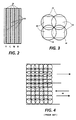
- Figure 1 is a perspective view schematically illustrating a multi-color, multi-head, scanning-type ink jet printer,
- Figure 2 is a view taken in the direction of line 2-2 of Figure 1, illustrating the nozzle arrays of the multi-color, multi-head, recording head assembly,
- Figure 3 illustrates the location of four adjacent ink spots relative to their pixel areas for high quality printing,
- Figure 4 illustrates two serial line scans deposited in the known deposition sequence,
- Figures 5A and 5B illustrate the location of selectively deposited liquid ink spots, in accordance with this invention, on a first and second line pass, respectively,
- Figures 6A and 6B illustrate the deposition of multi-color spots on a first and second line pass, respectively, in accordance with the known deposition sequence, and
- Figures 7A and 7B illustrate the deposition of multi-color spots on a first and second line pass in accordance with the present invention.
- Turning now to Figure 1, there is shown a multi-color,
multi-head printing mechanism 10 including acarriage 12 mounted for reciprocation (in the direction arrow of A-A) uponguide rails drive belt 18 supported betweenidler pulley 20 anddrive pulley 22, and driven bymotor 24. In order to make full-color recordings, recordinghead cartridges carriage 12. Each cartridge holder will include the appropriate mechanical, electrical and fluidic couplings for its respective head cartridge, so that selected ink drivers may be activated in response to a suitable drive signal to expel ink onto arecording substrate 28 supported upon aplaten 30. Although the substrate may be formed of any suitable material, such as paper, our invention has particular advantages for use with overhead transparency films. - In Figure 2, it can be seen that each head cartridge 26 (Y, C, M and B) is provided with an array of aligned nozzles 32 (schematically illustrated as being of circular cross-section). For a resolution of 12 spots per mm, each nozzle would be on the order of 25 µm in diameter and located on 84 µm centers. By appropriately spacing the head cartridge from the recording substrate, this arrangement results in spots on vertically aligned pixel centers spaced 84 µm apart. For obtaining the same horizontal resolution, the firing rate of the nozzles must be controlled so that the spots are also deposited onto 84 µm pixel centers.
- In order to achieve high quality print copy it is desired that there be complete area coverage with no "white" spaces between spots. This requires the relationship of
spots 34 topixels 36 to be as illustrated in Figure 3. By selecting a spot size diameter to be substantially equal to √2 times the pixel center-to-center distance, the spot size will be about 119 µm in diameter. Diagonally adjacent spots will just touch while horizontally and vertically adjacent spots will overlap, resulting in 100% pixel area coverage. - A representation of two subsequent scan lines deposited in the known manner, is shown in Figure 4. Solid area coverage is obtained by firing all of the vertical nozzles, simultaneously, at each horizontal position. Every pixel area is covered. At a drop deposition rate of 3KHz, horizontally aligned spots are deposited about 0.3 milliseconds apart. After the first line has been printed, the second line may be printed on the return stroke of the carriage, or it may be printed on a second forward stroke. The sequence of spot placement is satisfactory for printing upon a paper substrate because the ink is rapidly absorbed into the paper and dries rapidly relative to the placement of horizontally and vertically adjacent spots. Unfortunately, because of the poor absorptive properties of overhead transparency film, the print quality obtained by the same spot placement and timing is unsatisfactory. We know that on a transparency film the liquid ink takes longer to dry and that it will take about 0.1 to 0.2 seconds after deposition for an ink drop to be sufficiently tacky to receive an overlapping drop without beading. There appears to be an inherent conflict in the print quality requirements of the known deposition sequence. On the one hand, in order to achieve the intense color saturation desired for projection purposes, total ink area coverage and overlapping of the spots is desirable, while on the other hand, horizontal and vertical overlapping of ink between adjacent spots, while it is still in its flowable state, as illustrated in Figure 4, will cause non-uniformities attributed to beading.
- In our sequencing pattern for depositing spots upon a transparency film, at least two passes are required per line. We use the checkerboard deposition pattern shown in Figures 5A and 5B for placing only diagonally adjacent spots in a single pass. On a first pass one set of diagonal spots is deposited and on a subsequent pass (in either the reverse or same direction) the complementary set of diagonal spots is deposited. The resultant pixel area coverage will be the same as that shown in Figure 3, but since the second pass will be deposited more than 0.2 seconds after the first array of spots, the ink will not flow freely. There is no significant overlapping of flowable ink spots in a single pass as the diagonally adjacent spots barely touch one another. Thus, although the liquid ink in each spot is still in a flowable state, it does not affect the surface tension of its neighbors. According to this method there will be no beading and color saturation will be excellent due to the approximately 160% total ink coverage (100% pixel area coverage plus about 60% overlap coverage).
- In spite of the fact that two passes are required in our deposition pattern sequence, there will be relatively little, if any, adverse impact upon marking speed which is limited by jetting frequency. Since each jet is fired only at every other horizontal pixel location, the traverse speed of each pass can be doubled. For example, if the known deposition process is accomplished at about 25 cm.sec⁻¹, our deposition process can be accomplished in two passes of about 50 cm.sec⁻¹. Of course, there may be some slight speed reduction due to runout and drive reversal in a bidirectional mode of operation and a somewhat slower operation yet if the carriage must be returned to its starting position for a second pass in the same direction.
- The above print pattern sequence has been described relative to the printing of the single colors black, yellow, magenta and cyan. When mixed colors are to be printed, one color spot is placed on top of another. For example, magenta and yellow yields red, yellow and cyan yields green and magenta and cyan yields blue. It is well known the subtractive color mixing will result in slightly different colors depending upon the order in which the inks are deposited. Therefore, the blue created by magenta upon cyan will differ in color hue from that created by cyan upon magenta. When mixed color printing is effected bidirectionally, one line at a time, in accordance with the well known ink jet printing methods, as illustrated in Figures 6A and 6B, the placement of the
head cartridges 26 requires that the order of overlap of the inks be reversed from line to line. This causes a disagreeable condition known as "color banding" wherein alternate lines of a single color area are different color hues. - Although mixed colors are formed by totally overlapping one color spot over another, there will be no beading relative to a single superimposed pixel area. Beading will still be a problem vis-a-vis horizontally and vertically adjacent mixed color spots if the known deposition sequence of Figures 6A and 6B is followed. However, by depositing the mixed color spots in the same checkerboard patterns as shown in Figures 7A and 7B beading will not occur, for the reasons explained above. It should be borne in mind that each pixel area will contain more ink and a somewhat longer period of time is needed to tackify the ink before the second complementary checkerboard pattern may be deposited. Since there is so much more ink deposited excellent color saturation will be obtained.
- In addition to aggravated beading, due to the large quantity of flowable ink in each spot in mixed color printing, the color banding problem described above will occur when printing, in the known deposition sequence, in a bidirectional mode. In US-A-4,593,295 (Matsufuji et al) the problem is solved, in one manner, by the provision of a tandem print head having two sets of reverse order mounted head cartridges for each color. In our invention color banding is eliminated despite the fact that the color ordering is reversed in a reverse printing pass. The reason will be apparent from an observation of Figures 7A and 7B. It can be seen that the different mixed color spots (i.e. magenta over cyan and cyan over magenta) will be positioned in an alternating checkerboard pattern rather than in alternating lines so that the colors blend and any difference will not be perceptible.
- In operation of a liquid ink printer in accordance with our invention, a suitable substrate will be fed into the machine. The recording medium may be either paper or an overhead transparency film. Its nature will either be sensed automatically by a suitable detector (usually a reflectivity or transmissivity device) in the printer or by the operator. In either case, a switch will be set to control the spot pattern sequence. If paper is detected, then the known printing sequence of Figure 4 is effected. If transparency film is detected, the mode of operation will be switched to our multiple pass checkerboard print pattern sequence with its attendant advantages.
Claims (9)
depositing a first pattern of ink spots on an area of the substrate in horizontally and vertically alternating pixel areas, and then depositing a second, complementary, pattern of ink spots in the remaining pixel areas.
means for depositing a first pattern of ink spots on an area of the substrate in horizontally and vertically alternating pixel areas, and for then depositing a second, complementary, pattern of ink spots in the remaining pixel areas.
Applications Claiming Priority (2)
| Application Number | Priority Date | Filing Date | Title |
|---|---|---|---|
| US76088 | 1987-07-21 | ||
| US07/076,088 US4748453A (en) | 1987-07-21 | 1987-07-21 | Spot deposition for liquid ink printing |
Publications (3)
| Publication Number | Publication Date |
|---|---|
| EP0300743A2 true EP0300743A2 (en) | 1989-01-25 |
| EP0300743A3 EP0300743A3 (en) | 1990-08-01 |
| EP0300743B1 EP0300743B1 (en) | 1993-12-15 |
Family
ID=22129862
Family Applications (1)
| Application Number | Title | Priority Date | Filing Date |
|---|---|---|---|
| EP88306617A Expired - Lifetime EP0300743B1 (en) | 1987-07-21 | 1988-07-20 | Improved spot deposition for liquid ink printing |
Country Status (5)
| Country | Link |
|---|---|
| US (1) | US4748453A (en) |
| EP (1) | EP0300743B1 (en) |
| JP (1) | JP2502346B2 (en) |
| CA (1) | CA1296947C (en) |
| DE (1) | DE3886289T2 (en) |
Cited By (25)
| Publication number | Priority date | Publication date | Assignee | Title |
|---|---|---|---|---|
| EP0400680A2 (en) * | 1989-06-02 | 1990-12-05 | Canon Kabushiki Kaisha | Recording apparatus, and method for forming plural dots in a pixel, for use therein |
| DE4004543A1 (en) * | 1990-02-14 | 1991-08-22 | Siemens Ag | Ink jet printing method for smooth foil - providing relative offset between individual points in successive raster lines |
| WO1992004191A1 (en) * | 1990-09-10 | 1992-03-19 | Mannesmann Ag | Process for reducing the quantity of ink applied to recording substrates by ink writing devices |
| EP0488724A2 (en) * | 1990-11-30 | 1992-06-03 | Canon Kabushiki Kaisha | Ink jet recording apparatus and method |
| EP0516420A2 (en) * | 1991-05-31 | 1992-12-02 | Canon Kabushiki Kaisha | Ink jet recording method and apparatus |
| DE4127560A1 (en) * | 1991-08-19 | 1993-02-25 | Mannesmann Ag | RECORDING PROCEDURE |
| EP0556959A1 (en) * | 1992-01-28 | 1993-08-25 | Canon Kabushiki Kaisha | Scan interval control in ink jet recording apparatus |
| DE4207623A1 (en) * | 1992-03-06 | 1993-09-16 | Inkjet Systems Gmbh Co Kg | High print quality printing for thermal ink jet printer - using print matrix subdivided into number or sub matrix groups that are selected to provide optimum printing of overlapping sections |
| EP0564252A2 (en) * | 1992-03-31 | 1993-10-06 | Canon Kabushiki Kaisha | Ink jet recording method and apparatus |
| EP0567288A2 (en) * | 1992-04-21 | 1993-10-27 | Canon Kabushiki Kaisha | Ink jet recording system using decomposed images |
| EP0595517A1 (en) * | 1992-10-16 | 1994-05-04 | Canon Kabushiki Kaisha | Ink jet recording method and apparatus |
| EP0622212A2 (en) * | 1993-04-30 | 1994-11-02 | Hewlett-Packard Company | Images printing method |
| EP0622211A2 (en) * | 1993-04-30 | 1994-11-02 | Hewlett-Packard Company | Method for ink jet printing on plastic recording media |
| EP0382023B1 (en) * | 1989-01-28 | 1996-05-22 | Canon Kabushiki Kaisha | Ink jet recording method and color ink jet recording device for practicing the same |
| EP0703086A3 (en) * | 1994-09-26 | 1998-06-03 | Xerox Corporation | Method and apparatus for printing having logic circuitry to reduce video data input rate |
| EP0856985A2 (en) * | 1997-01-31 | 1998-08-05 | Canon Kabushiki Kaisha | Printing apparatus and printing control method |
| EP0863479A3 (en) * | 1997-03-04 | 2000-08-16 | Hewlett-Packard Company | Method and apparatus for multipass colour ink jet printing |
| EP1029693A1 (en) * | 1999-02-17 | 2000-08-23 | Hewlett-Packard Company | Printing with multiple passes |
| US6157461A (en) * | 1997-10-27 | 2000-12-05 | Hewlett-Packard Company | Method of generating randomized masks to improve image quality on a printing medium |
| EP1088670A2 (en) * | 1999-09-30 | 2001-04-04 | Canon Kabushiki Kaisha | Two-way print apparatus and print method |
| EP1088669A2 (en) * | 1999-09-30 | 2001-04-04 | Canon Kabushiki Kaisha | Printing apparatus and printing method |
| JP2001352962A (en) * | 2000-04-20 | 2001-12-25 | Hauni Maschinenbau Ag | Method and apparatus for coating covering material for rodlike article in tobacco processing industry with paste |
| EP1387312A1 (en) * | 1993-06-30 | 2004-02-04 | Canon Kabushiki Kaisha | Ink-jet recording apparatus and method using asynchronous masks |
| US6899413B2 (en) | 2000-01-25 | 2005-05-31 | Canon Kabushiki Kaisha | Bidirectional printing method and apparatus with reduced color unevenness |
| WO2006125779A1 (en) * | 2005-05-25 | 2006-11-30 | Agfa Graphics Nv | Image processing method and apparatus for improving the image quality of a dot matrix printer |
Families Citing this family (162)
| Publication number | Priority date | Publication date | Assignee | Title |
|---|---|---|---|---|
| US5220342A (en) * | 1988-04-26 | 1993-06-15 | Canon Kabushiki Kaisha | Ink jet recording method |
| JPH024523A (en) * | 1988-06-22 | 1990-01-09 | Canon Inc | Ink jet recording method and apparatus used therefor |
| US4963882B1 (en) * | 1988-12-27 | 1996-10-29 | Hewlett Packard Co | Printing of pixel locations by an ink jet printer using multiple nozzles for each pixel or pixel row |
| EP0376346B1 (en) * | 1988-12-30 | 1996-04-10 | Canon Kabushiki Kaisha | Ink jet recording apparatus |
| US6406118B1 (en) | 1988-12-30 | 2002-06-18 | Canon Kabushiki Kaisha | Ink jet recording apparatus having a heat fixing mechanism |
| US5216445A (en) * | 1989-01-11 | 1993-06-01 | Canon Kabushiki Kaisha | Ink jet recording method using plural dots to form each recording unit |
| DE69019380T2 (en) * | 1989-01-11 | 1995-10-26 | Canon Kk | Ink jet recording process. |
| EP0428658A4 (en) * | 1989-05-31 | 1992-04-22 | Spectra, Inc. | Reduced banding in bidirectional ink jet printing |
| JP2810701B2 (en) * | 1989-05-31 | 1998-10-15 | キヤノン株式会社 | Ink jet recording head and ink jet recording apparatus |
| US4965593A (en) * | 1989-07-27 | 1990-10-23 | Hewlett-Packard Company | Print quality of dot printers |
| US5583550A (en) * | 1989-09-29 | 1996-12-10 | Hewlett-Packard Company | Ink drop placement for improved imaging |
| US4967203A (en) * | 1989-09-29 | 1990-10-30 | Hewlett-Packard Company | Interlace printing process |
| US4999646A (en) * | 1989-11-29 | 1991-03-12 | Hewlett-Packard Company | Method for enhancing the uniformity and consistency of dot formation produced by color ink jet printing |
| US5057852A (en) * | 1989-12-18 | 1991-10-15 | Eastman Kodak Company | Printhead for color printer providing image edge enhancement |
| US5239312A (en) * | 1990-02-02 | 1993-08-24 | Dataproducts Corporation | Interlaced ink jet printing |
| JP2863242B2 (en) * | 1990-02-02 | 1999-03-03 | キヤノン株式会社 | Ink jet recording apparatus and method |
| US5070345A (en) * | 1990-02-02 | 1991-12-03 | Dataproducts Corporation | Interlaced ink jet printing |
| US5012257A (en) * | 1990-03-16 | 1991-04-30 | Hewlett-Packard Company | Ink jet color graphics printing |
| ES2091288T3 (en) | 1990-04-20 | 1996-11-01 | Canon Kk | PRINTING DEVICE. |
| DE4015799A1 (en) * | 1990-05-14 | 1991-11-21 | Siemens Ag | Bi-directional serial ink-jet printer setting-up method - using test patterns with part of one lying symmetrically in space in other printed in opposite direction |
| CA2048048C (en) * | 1990-09-17 | 2000-11-28 | Hewlett-Packard Company | Ink drop placement for improving imaging |
| JPH04235044A (en) * | 1991-01-11 | 1992-08-24 | Canon Inc | Recording apparatus |
| JP2704339B2 (en) * | 1991-02-01 | 1998-01-26 | テクトロニクス・インコーポレイテッド | Interlaced printing method |
| US6012797A (en) * | 1991-03-29 | 2000-01-11 | Canon Kabushiki Kaisha | Method for driving an ink jet recording head having improved discharge stability and recording apparatus having the same |
| JP3060330B2 (en) * | 1991-07-09 | 2000-07-10 | キヤノン株式会社 | Image processing apparatus and method |
| ATE235376T1 (en) * | 1991-07-30 | 2003-04-15 | Canon Kk | APPARATUS AND METHOD FOR INKJET RECORDING |
| CA2074875C (en) * | 1991-08-02 | 2000-02-15 | Miyuki Matsubara | Ink jet recording method |
| US5880757A (en) * | 1991-11-04 | 1999-03-09 | Hewlett-Packard Company | Print resolution enhancement by adjusting printhead position |
| US5247315A (en) * | 1992-02-06 | 1993-09-21 | Gerber Scientific Products, Inc. | Method of printing a graphic having uniform ink density on an emulsion coated printing screen |
| CN1096943C (en) | 1992-02-26 | 2002-12-25 | 佳能株式会社 | Ink jet record method and recorded material thereof |
| US6116728A (en) * | 1992-02-26 | 2000-09-12 | Canon Kabushiki Kaisha | Ink jet recording method and apparatus and recorded matter |
| US6036300A (en) * | 1992-02-26 | 2000-03-14 | Canon Kabushiki Kaisha | Method for recording image and apparatus therefor and recorded matter by such an apparatus |
| AU696112B2 (en) * | 1992-04-21 | 1998-09-03 | Canon Kabushiki Kaisha | Ink jet recording system using decomposed images |
| US6106102A (en) * | 1992-05-01 | 2000-08-22 | Hewlett-Packard Company | Odd number of passes, odd number of advances, and separated-diagonal-line masking, in liquid-ink printers |
| EP0902389B1 (en) * | 1992-05-25 | 2006-03-08 | Canon Kabushiki Kaisha | Image forming method and apparatus |
| JP3176130B2 (en) * | 1992-07-06 | 2001-06-11 | キヤノン株式会社 | Inkjet recording method |
| JP3155832B2 (en) * | 1992-09-25 | 2001-04-16 | キヤノン株式会社 | Ink jet recording method and recording apparatus |
| US5512923A (en) * | 1992-09-30 | 1996-04-30 | Hewlett-Packard Company | Color variation control method for ink-jet printers |
| JP3161094B2 (en) * | 1992-10-08 | 2001-04-25 | 富士ゼロックス株式会社 | Recording method in ink jet recording apparatus |
| JP3205082B2 (en) * | 1992-10-13 | 2001-09-04 | キヤノン株式会社 | Image forming method and apparatus |
| DE69330081T2 (en) * | 1992-10-30 | 2001-08-30 | Canon Kk | Ink jet recording system and device |
| JP3093489B2 (en) * | 1992-11-12 | 2000-10-03 | キヤノン株式会社 | Inkjet recording method |
| JP3029165B2 (en) * | 1992-12-04 | 2000-04-04 | キヤノン株式会社 | Ink jet recording device |
| ATE221463T1 (en) | 1993-02-05 | 2002-08-15 | Canon Kk | COLOR BEAM RECORDING DEVICE |
| DE69435024T2 (en) * | 1993-05-27 | 2008-06-12 | Canon K.K. | Method and apparatus for ink jet recording |
| US5506609A (en) * | 1993-06-30 | 1996-04-09 | Apple Computer, Inc. | Minimizing color bleed while maximizing throughput for color printing |
| IT1261240B (en) * | 1993-08-19 | 1996-05-09 | Olivetti Canon Ind Spa | POINT PRINTING METHOD AND RELATED INK JET PRINT HEAD. |
| US5883644A (en) * | 1993-10-29 | 1999-03-16 | Hewlett-Packard Company | Resolution-dependent and color-dependent print masking |
| US5689289A (en) * | 1993-11-30 | 1997-11-18 | Canon Kabushiki Kaisha | Image recording apparatus |
| US5790150A (en) * | 1994-02-17 | 1998-08-04 | Colorspan Corporation | Method for controlling an ink jet printer in a multipass printing mode |
| JP3488304B2 (en) | 1994-03-10 | 2004-01-19 | ゼロックス・コーポレーション | Inkjet printer control method |
| US5502555A (en) * | 1994-07-11 | 1996-03-26 | Xerox Corporation | Printing system having an image characteristics automatic method and apparatus for copy sheet reselection |
| SE503955C2 (en) * | 1994-09-19 | 1996-10-07 | Array Printers Ab | Method and apparatus for feeding toner particles in a printer unit |
| US5568169A (en) * | 1994-10-19 | 1996-10-22 | Xerox Corporation | Method and apparatus using two different black inks to reduce intercolor bleeding and provide high quality edge definition with thermal ink jet systems |
| JP2001509744A (en) * | 1994-12-15 | 2001-07-24 | アライ プリンターズ アクティエボラーグ | Serial printing system to attach powder particles directly |
| US5812156A (en) * | 1997-01-21 | 1998-09-22 | Hewlett-Packard Company | Apparatus controlled by data from consumable parts with incorporated memory devices |
| US5992962A (en) * | 1994-12-22 | 1999-11-30 | Hewlett-Packard Company | Print masks for inkjet printers |
| US5610638A (en) * | 1995-01-03 | 1997-03-11 | Xerox Corporation | Temperature sensitive print mode selection |
| JP3164745B2 (en) * | 1995-02-13 | 2001-05-08 | キヤノン株式会社 | INK JET PRINTING APPARATUS AND INK JET PRINTING METHOD |
| US5818480A (en) * | 1995-02-14 | 1998-10-06 | Array Printers Ab | Method and apparatus to control electrodes in a print unit |
| US5847721A (en) † | 1995-03-06 | 1998-12-08 | Canon Kabushiki Kaisha | Recording apparatus and method |
| JP3423478B2 (en) * | 1995-05-30 | 2003-07-07 | キヤノン株式会社 | Recording device |
| FR2734759B1 (en) * | 1995-05-31 | 1998-03-27 | Oce Graphics France | DOT IMAGE PRINTING PROCESS USING A MULTIPOINT PRINT HEAD, IN SEVERAL PASSES |
| JP3175539B2 (en) * | 1995-06-21 | 2001-06-11 | 富士ゼロックス株式会社 | Recording device and print control method |
| US6000786A (en) * | 1995-09-19 | 1999-12-14 | Array Printers Publ. Ab | Method and apparatus for using dual print zones to enhance print quality |
| US6015206A (en) * | 1995-11-21 | 2000-01-18 | Lexmark International, Inc. | Bleed avoiding, color ink jet printing |
| US5764263A (en) * | 1996-02-05 | 1998-06-09 | Xerox Corporation | Printing process, apparatus, and materials for the reduction of paper curl |
| SE506484C2 (en) | 1996-03-12 | 1997-12-22 | Ito Engineering Ab | Toner-jet printing plant with electrically shielded matrix |
| SE506483C2 (en) | 1996-03-12 | 1997-12-22 | Ito Engineering Ab | Toner-jet printing press |
| US5847733A (en) * | 1996-03-22 | 1998-12-08 | Array Printers Ab Publ. | Apparatus and method for increasing the coverage area of a control electrode during direct electrostatic printing |
| US5809215A (en) * | 1996-04-18 | 1998-09-15 | Lexmark International, Inc. | Method of printing to inhibit intercolor bleeding |
| US5971526A (en) * | 1996-04-19 | 1999-10-26 | Array Printers Ab | Method and apparatus for reducing cross coupling and dot deflection in an image recording apparatus |
| US5818490A (en) * | 1996-05-02 | 1998-10-06 | Array Printers Ab | Apparatus and method using variable control signals to improve the print quality of an image recording apparatus |
| US5695820A (en) * | 1996-06-20 | 1997-12-09 | Hewlett-Packard Company | Method for alleviating marangoni flow-induced print defects in ink-jet printing |
| US5870112A (en) * | 1996-06-25 | 1999-02-09 | Xerox Corporation | Dot scheduling for liquid ink printers |
| US5956064A (en) * | 1996-10-16 | 1999-09-21 | Array Printers Publ. Ab | Device for enhancing transport of proper polarity toner in direct electrostatic printing |
| US5959648A (en) * | 1996-11-27 | 1999-09-28 | Array Printers Ab | Device and a method for positioning an array of control electrodes in a printhead structure for direct electrostatic printing |
| US5966152A (en) * | 1996-11-27 | 1999-10-12 | Array Printers Ab | Flexible support apparatus for dynamically positioning control units in a printhead structure for direct electrostatic printing |
| US5889542A (en) * | 1996-11-27 | 1999-03-30 | Array Printers Publ. Ab | Printhead structure for direct electrostatic printing |
| US5984456A (en) * | 1996-12-05 | 1999-11-16 | Array Printers Ab | Direct printing method utilizing dot deflection and a printhead structure for accomplishing the method |
| US6011944A (en) * | 1996-12-05 | 2000-01-04 | Array Printers Ab | Printhead structure for improved dot size control in direct electrostatic image recording devices |
| US5870117A (en) * | 1997-01-21 | 1999-02-09 | Xerox Corporation | Liquid ink printer including a camming printhead to enable increased resolution printing |
| US6012801A (en) * | 1997-02-18 | 2000-01-11 | Array Printers Ab | Direct printing method with improved control function |
| US6067405A (en) | 1997-03-04 | 2000-05-23 | Hewlett-Packard Company | Multipass color printmasks based on location rules to minimize hue shift, banding and coalescence |
| US6019454A (en) | 1997-03-04 | 2000-02-01 | Hewlett-Packard Company | Multipass inkjet printmodes with randomized dot placement, to minimize patterning and liquid loading |
| US6082849A (en) * | 1997-03-10 | 2000-07-04 | Hewlett-Packard Company | Random printmasks in a multilevel inkjet printer |
| JP2001514587A (en) * | 1997-03-10 | 2001-09-11 | アライ プリンターズ アクチボラゲット | Direct printing method with improved control function |
| US6010205A (en) * | 1997-03-12 | 2000-01-04 | Raster Graphics Inc. | Method and apparatus for improved printing |
| JP3562308B2 (en) * | 1997-05-14 | 2004-09-08 | セイコーエプソン株式会社 | Printing apparatus and printing method |
| US6170932B1 (en) * | 1997-05-20 | 2001-01-09 | Seiko Epson Corporation | Printing system, method of printing, and recording medium to realize the method |
| US6174037B1 (en) | 1997-06-02 | 2001-01-16 | Xerox Corporation | Multiple pass ink jet printer with optimized power supply |
| US6132029A (en) * | 1997-06-09 | 2000-10-17 | Array Printers Ab | Direct printing method with improved control function |
| US6017115A (en) * | 1997-06-09 | 2000-01-25 | Array Printers Ab | Direct printing method with improved control function |
| US5975672A (en) | 1997-07-24 | 1999-11-02 | Eastman Kodak Company | Ink jet printing apparatus and method accommodating printing mode control |
| WO1999008875A1 (en) | 1997-08-01 | 1999-02-25 | Encad, Inc. | Ink-jet printer, method and system compensating for nonfunctional print elements |
| US6102526A (en) * | 1997-12-12 | 2000-08-15 | Array Printers Ab | Image forming method and device utilizing chemically produced toner particles |
| US6086186A (en) * | 1997-12-19 | 2000-07-11 | Array Printers Ab | Apparatus for positioning a control electrode array in a direct electrostatic printing device |
| US6209990B1 (en) | 1997-12-19 | 2001-04-03 | Array Printers Ab | Method and apparatus for coating an intermediate image receiving member to reduce toner bouncing during direct electrostatic printing |
| US6030070A (en) * | 1997-12-19 | 2000-02-29 | Array Printers Ab | Direct electrostatic printing method and apparatus |
| US6257708B1 (en) | 1997-12-19 | 2001-07-10 | Array Printers Ab | Direct electrostatic printing apparatus and method for controlling dot position using deflection electrodes |
| US6070967A (en) * | 1997-12-19 | 2000-06-06 | Array Printers Ab | Method and apparatus for stabilizing an intermediate image receiving member during direct electrostatic printing |
| US6027206A (en) * | 1997-12-19 | 2000-02-22 | Array Printers Ab | Method and apparatus for cleaning the printhead structure during direct electrostatic printing |
| US6208365B1 (en) * | 1997-12-26 | 2001-03-27 | Noritsu Koki Co. | Vacuum fluorescent printer |
| US6089693A (en) * | 1998-01-08 | 2000-07-18 | Xerox Corporation | Pagewidth ink jet printer including multiple pass defective nozzle correction |
| US6234605B1 (en) | 1998-01-08 | 2001-05-22 | Xerox Corporation | Multiple resolution pagewidth ink jet printer including a positionable pagewidth printbear |
| US6046822A (en) * | 1998-01-09 | 2000-04-04 | Eastman Kodak Company | Ink jet printing apparatus and method for improved accuracy of ink droplet placement |
| JPH11208029A (en) * | 1998-01-21 | 1999-08-03 | Seiko Epson Corp | Printing apparatus, printing method and storage medium |
| US6019466A (en) * | 1998-02-02 | 2000-02-01 | Xerox Corporation | Multicolor liquid ink printer and method for printing on plain paper |
| US6290328B1 (en) * | 1998-02-05 | 2001-09-18 | Canon Kabushiki Kaisha | Multi-pass banded printing |
| US6199971B1 (en) | 1998-02-24 | 2001-03-13 | Arrray Printers Ab | Direct electrostatic printing method and apparatus with increased print speed |
| US6074045A (en) * | 1998-03-04 | 2000-06-13 | Array Printers Ab | Printhead structure in an image recording device |
| US6174048B1 (en) | 1998-03-06 | 2001-01-16 | Array Printers Ab | Direct electrostatic printing method and apparatus with apparent enhanced print resolution |
| US6626527B1 (en) * | 1998-03-12 | 2003-09-30 | Creo Americas, Inc. | Interleaved printing |
| US6081283A (en) * | 1998-03-19 | 2000-06-27 | Array Printers Ab | Direct electrostatic printing method and apparatus |
| US6082850A (en) * | 1998-03-19 | 2000-07-04 | Array Printers Ab | Apparatus and method for controlling print density in a direct electrostatic printing apparatus by adjusting toner flow with regard to relative positioning of rows of apertures |
| US6102525A (en) * | 1998-03-19 | 2000-08-15 | Array Printers Ab | Method and apparatus for controlling the print image density in a direct electrostatic printing apparatus |
| US6124946A (en) * | 1998-04-30 | 2000-09-26 | Hewlett-Packard Company | Multi-pass pseudo random masking system and method of using same |
| US6019449A (en) * | 1998-06-05 | 2000-02-01 | Hewlett-Packard Company | Apparatus controlled by data from consumable parts with incorporated memory devices |
| ATE215238T1 (en) | 1998-06-15 | 2002-04-15 | Array Printers Ab | METHOD AND APPARATUS FOR DIRECT ELECTROSTATIC PRINTING |
| EP0965455A1 (en) | 1998-06-15 | 1999-12-22 | Array Printers Ab | Direct electrostatic printing method and apparatus |
| US6364454B1 (en) | 1998-09-30 | 2002-04-02 | Xerox Corporation | Acoustic ink printing method and system for improving uniformity by manipulating nonlinear characteristics in the system |
| EP1120253B1 (en) * | 1999-03-10 | 2007-01-24 | Seiko Epson Corporation | Adjustment of displacement of dot forming position by using information that no dot is to be formed for each pixel unit |
| US6338544B1 (en) | 1999-06-29 | 2002-01-15 | Xerox Corporation | Reduction of stitch joint error by alternating print head firing mode |
| JP2001010088A (en) * | 1999-07-02 | 2001-01-16 | Seiko Epson Corp | Printer capable of suppressing shift of dot formed position, method for controlling and recording medium |
| JP4095210B2 (en) | 1999-08-24 | 2008-06-04 | キヤノン株式会社 | Recording method and recording apparatus |
| US6309047B1 (en) | 1999-11-23 | 2001-10-30 | Xerox Corporation | Exceeding the surface settling limit in acoustic ink printing |
| US6595612B1 (en) * | 2000-02-23 | 2003-07-22 | Mutoh Industries Ltd. | Inkjet printer capable of minimizing chromatic variation in adjacent print swaths when printing color images in bidirectional model |
| US6523937B1 (en) * | 2000-04-07 | 2003-02-25 | Transact Technologies, Inc. | Method and apparatus for single pass two-color ink jet point of sale (POS) printing |
| US6754551B1 (en) | 2000-06-29 | 2004-06-22 | Printar Ltd. | Jet print apparatus and method for printed circuit board manufacturing |
| US6934054B1 (en) | 2000-08-04 | 2005-08-23 | Transact Technologies Incorporated | Method and apparatus for two-color thermal point of sale (POS) printing |
| JP4931164B2 (en) | 2000-08-30 | 2012-05-16 | キヤノン株式会社 | Mask pattern manufacturing method |
| US6900907B2 (en) | 2000-12-08 | 2005-05-31 | Xerox Corporation | Overlapping drop assignment for multi-level ink jet printing |
| NL1018114C2 (en) | 2001-05-21 | 2002-11-25 | Oce Tech Bv | Inkjet printer and a method for printing on a receiving material. |
| US6648440B2 (en) * | 2001-06-27 | 2003-11-18 | Hewlett-Packard Development Company, L.P. | System and method for using lower data rates for printheads with closely spaced nozzles |
| US6508535B1 (en) | 2002-01-16 | 2003-01-21 | Xerox Corporation | Systems and methods for randomized dot scheduling for multipass printing |
| US8011299B2 (en) * | 2002-07-01 | 2011-09-06 | Inca Digital Printers Limited | Printing with ink |
| US6702425B1 (en) | 2002-09-23 | 2004-03-09 | Eastman Kodak Company | Coalescence-free inkjet printing by controlling drop spreading on/in a receiver |
| US6729706B1 (en) | 2003-02-14 | 2004-05-04 | Eastman Kodak Company | Large area marking device and method for printing |
| JP4261980B2 (en) * | 2003-05-16 | 2009-05-13 | キヤノン株式会社 | Image forming method |
| US6951375B2 (en) * | 2003-05-20 | 2005-10-04 | Eastman Kodak Company | Large area marking device and method for printing |
| JP2005125658A (en) * | 2003-10-24 | 2005-05-19 | Seiko Epson Corp | Image processor, image processing method, printer, printing method, and program for realizing them |
| JP4574163B2 (en) * | 2003-12-12 | 2010-11-04 | キヤノン株式会社 | Inkjet recording apparatus and inkjet recording method |
| US20050156964A1 (en) * | 2004-01-19 | 2005-07-21 | Konica Minolta Medical & Graphic, Inc. | Ink-jet recording apparatus |
| US20050156965A1 (en) * | 2004-01-19 | 2005-07-21 | Konica Minolta Medical & Graphic, Inc. | Inkjet recording apparatus |
| US7093918B2 (en) | 2004-04-16 | 2006-08-22 | Hewlett-Packard Development Company, L.P. | Double dotting for grain equalization |
| US20050248631A1 (en) * | 2004-05-10 | 2005-11-10 | Pinard Adam I | Stitched printing system |
| JP2007136676A (en) * | 2005-11-14 | 2007-06-07 | Seiko Epson Corp | Printer and printing head |
| TWI262134B (en) * | 2005-12-30 | 2006-09-21 | Ind Tech Res Inst | A multiple passes print apparatus and method |
| EP1914668A1 (en) * | 2006-10-16 | 2008-04-23 | Agfa Graphics N.V. | Image processing method and apparatus for improving image quality in dot matrix printer |
| WO2008046760A1 (en) * | 2006-10-16 | 2008-04-24 | Agfa Graphics Nv | Image processing method and apparatus for improving image quality in dot matrix printer |
| JP2008173880A (en) * | 2007-01-19 | 2008-07-31 | Sony Corp | Printing device, recording medium driver, and printing method |
| WO2008124680A1 (en) | 2007-04-05 | 2008-10-16 | Marvell International Ltd. | Inkjet printer having switched firing of adjacent nozzles applying common color |
| JP5483834B2 (en) * | 2007-06-28 | 2014-05-07 | キヤノン株式会社 | Image processing apparatus and image processing method |
| EP2025520A1 (en) * | 2007-08-16 | 2009-02-18 | Mutoh Europe N.V. | Colour dot matrix print method and printing apparatus |
| DE102008024660A1 (en) * | 2008-05-21 | 2009-11-26 | Manroland Ag | Device for linear displaceable storage of e.g. camera of web-fed rotary printing press, has data- and/or current line whose line section runs till cable exit in guide path, where cable exit is provided at or near axial end of guide path |
| WO2010065697A1 (en) * | 2008-12-03 | 2010-06-10 | Videojet Technologies Inc. | An inkjet printing system and method |
| US8256875B2 (en) * | 2009-06-25 | 2012-09-04 | Lexmark International, Inc. | Two pass print mode method and apparatus for limiting wind-related print defects |
| JP5519462B2 (en) * | 2010-10-06 | 2014-06-11 | 富士機械製造株式会社 | Method for forming a multilayer printing section |
| JP2014061592A (en) * | 2011-01-18 | 2014-04-10 | Fujifilm Corp | Image formation device, image formation method and threshold value matrix generating device |
| JP2015016671A (en) * | 2013-07-12 | 2015-01-29 | セイコーエプソン株式会社 | Dot recording device, dot recording method and computer program for the same |
| US11345116B2 (en) * | 2016-07-18 | 2022-05-31 | Beaulieu International Group Nv | Multi-layered sheet suitable as floor or wall covering exhibiting a three-dimensional relief and a decorative image |
| US10899125B1 (en) | 2019-12-11 | 2021-01-26 | Shanghai Realfast Digital Technology Co., Ltd | Printing stitched swaths having complementary irregular boundaries |
Citations (5)
| Publication number | Priority date | Publication date | Assignee | Title |
|---|---|---|---|---|
| GB2033844A (en) * | 1978-10-16 | 1980-05-29 | Xerox Corp | Multi-pass matrix printing |
| US4593295A (en) * | 1982-06-08 | 1986-06-03 | Canon Kabushiki Kaisha | Ink jet image recording device with pitch-shifted recording elements |
| US4617580A (en) * | 1983-08-26 | 1986-10-14 | Canon Kabushiki Kaisha | Apparatus for recording on different types of mediums |
| EP0207788A2 (en) * | 1985-07-03 | 1987-01-07 | Lexmark International, Inc. | Apparatus and method for displaying dot matrix characters in enhanced form |
| EP0244604A2 (en) * | 1986-04-15 | 1987-11-11 | Lexmark International, Inc. | Method and apparatus for quieting the operation of a dot matrix printer |
Family Cites Families (3)
| Publication number | Priority date | Publication date | Assignee | Title |
|---|---|---|---|---|
| JPS5843150B2 (en) * | 1976-03-24 | 1983-09-24 | 大同特殊鋼株式会社 | Marking method |
| JPS55113573A (en) * | 1979-02-24 | 1980-09-02 | Ricoh Co Ltd | Ink jet plotter |
| DE3037774C2 (en) * | 1980-10-06 | 1982-06-16 | Siemens AG, 1000 Berlin und 8000 München | Method and arrangement for displaying multicolored halftone images |
-
1987
- 1987-07-21 US US07/076,088 patent/US4748453A/en not_active Expired - Lifetime
-
1988
- 1988-05-19 CA CA000567272A patent/CA1296947C/en not_active Expired - Lifetime
- 1988-07-14 JP JP63176210A patent/JP2502346B2/en not_active Expired - Fee Related
- 1988-07-20 EP EP88306617A patent/EP0300743B1/en not_active Expired - Lifetime
- 1988-07-20 DE DE3886289T patent/DE3886289T2/en not_active Expired - Fee Related
Patent Citations (5)
| Publication number | Priority date | Publication date | Assignee | Title |
|---|---|---|---|---|
| GB2033844A (en) * | 1978-10-16 | 1980-05-29 | Xerox Corp | Multi-pass matrix printing |
| US4593295A (en) * | 1982-06-08 | 1986-06-03 | Canon Kabushiki Kaisha | Ink jet image recording device with pitch-shifted recording elements |
| US4617580A (en) * | 1983-08-26 | 1986-10-14 | Canon Kabushiki Kaisha | Apparatus for recording on different types of mediums |
| EP0207788A2 (en) * | 1985-07-03 | 1987-01-07 | Lexmark International, Inc. | Apparatus and method for displaying dot matrix characters in enhanced form |
| EP0244604A2 (en) * | 1986-04-15 | 1987-11-11 | Lexmark International, Inc. | Method and apparatus for quieting the operation of a dot matrix printer |
Non-Patent Citations (3)
| Title |
|---|
| PATENT ABSTRACTS OF JAPAN * |
| PATENT ABSTRACTS OF JAPAN, vol. 7, no. 163 (M-229)(1308), 16 July 1983; JP-A-58 69071 * |
| PATENT ABSTRACTS OF JAPAN, vol. 9, no. 34 (M357)(1757), 14 February 1985; JP-A-59 176050 * |
Cited By (55)
| Publication number | Priority date | Publication date | Assignee | Title |
|---|---|---|---|---|
| EP0382023B1 (en) * | 1989-01-28 | 1996-05-22 | Canon Kabushiki Kaisha | Ink jet recording method and color ink jet recording device for practicing the same |
| US6106100A (en) * | 1989-06-02 | 2000-08-22 | Canon Kabushiki Kaisha | Recording apparatus and method for forming plural dots in a pixel |
| EP0400680A3 (en) * | 1989-06-02 | 1991-07-03 | Canon Kabushiki Kaisha | Recording apparatus, and method for forming plural dots in a pixel, for use therein |
| EP0400680A2 (en) * | 1989-06-02 | 1990-12-05 | Canon Kabushiki Kaisha | Recording apparatus, and method for forming plural dots in a pixel, for use therein |
| DE4004543A1 (en) * | 1990-02-14 | 1991-08-22 | Siemens Ag | Ink jet printing method for smooth foil - providing relative offset between individual points in successive raster lines |
| WO1992004191A1 (en) * | 1990-09-10 | 1992-03-19 | Mannesmann Ag | Process for reducing the quantity of ink applied to recording substrates by ink writing devices |
| EP0488724A3 (en) * | 1990-11-30 | 1992-12-16 | Canon Kabushiki Kaisha | Ink jet recording apparatus and method |
| EP0706889A1 (en) * | 1990-11-30 | 1996-04-17 | Canon Kabushiki Kaisha | Ink jet recording apparatus and method |
| US5745145A (en) * | 1990-11-30 | 1998-04-28 | Canon Kabushiki Kaisha | Ink jet recording apparatus and method |
| EP0488724A2 (en) * | 1990-11-30 | 1992-06-03 | Canon Kabushiki Kaisha | Ink jet recording apparatus and method |
| EP0516420A3 (en) * | 1991-05-31 | 1992-12-30 | Canon Kabushiki Kaisha | Ink jet recording method and apparatus |
| EP0516420A2 (en) * | 1991-05-31 | 1992-12-02 | Canon Kabushiki Kaisha | Ink jet recording method and apparatus |
| US5917519A (en) * | 1991-05-31 | 1999-06-29 | Canon Kabushiki Kaisha | Ink jet recording method and apparatus for recording with multiple thinned images |
| DE4127560A1 (en) * | 1991-08-19 | 1993-02-25 | Mannesmann Ag | RECORDING PROCEDURE |
| WO1993004443A1 (en) * | 1991-08-19 | 1993-03-04 | Mannesmann Ag | Printing process |
| EP0556959A1 (en) * | 1992-01-28 | 1993-08-25 | Canon Kabushiki Kaisha | Scan interval control in ink jet recording apparatus |
| US5841451A (en) * | 1992-01-28 | 1998-11-24 | Canon Kabushiki Kaisha | Scan interval control in ink jet recording apparatus |
| DE4207623C2 (en) * | 1992-03-06 | 1998-08-27 | Eastman Kodak Co | Method of printing with a serial inkjet printer |
| DE4207623A1 (en) * | 1992-03-06 | 1993-09-16 | Inkjet Systems Gmbh Co Kg | High print quality printing for thermal ink jet printer - using print matrix subdivided into number or sub matrix groups that are selected to provide optimum printing of overlapping sections |
| EP0564252A3 (en) * | 1992-03-31 | 1994-04-27 | Canon Kk | |
| US6130685A (en) * | 1992-03-31 | 2000-10-10 | Canon Kabushiki Kaisha | Method for recording an image with multiple scannings of a recording head having groups of nozzles |
| EP0564252A2 (en) * | 1992-03-31 | 1993-10-06 | Canon Kabushiki Kaisha | Ink jet recording method and apparatus |
| US5633663A (en) * | 1992-03-31 | 1997-05-27 | Canon Kabushiki Kaisha | Ink jet recording method and apparatus |
| CN1071467C (en) * | 1992-04-21 | 2001-09-19 | 佳能株式会社 | Ink jet recording system using decomposed images |
| EP0567288A3 (en) * | 1992-04-21 | 1994-03-16 | Canon Kk | |
| US6217142B1 (en) | 1992-04-21 | 2001-04-17 | Canon Kabushiki Kaisha | Ink jet recording system using decomposed images |
| EP0567288A2 (en) * | 1992-04-21 | 1993-10-27 | Canon Kabushiki Kaisha | Ink jet recording system using decomposed images |
| US6491372B1 (en) | 1992-10-16 | 2002-12-10 | Canon Kabushiki Kaisha | Ink jet recording method and ink jet recording apparatus |
| EP0595517A1 (en) * | 1992-10-16 | 1994-05-04 | Canon Kabushiki Kaisha | Ink jet recording method and apparatus |
| US6779872B2 (en) | 1992-10-16 | 2004-08-24 | Canon Kabushiki Kaisha | Ink jet recording method and ink jet recording apparatus |
| EP0622211A2 (en) * | 1993-04-30 | 1994-11-02 | Hewlett-Packard Company | Method for ink jet printing on plastic recording media |
| EP0622212A2 (en) * | 1993-04-30 | 1994-11-02 | Hewlett-Packard Company | Images printing method |
| EP0622211A3 (en) * | 1993-04-30 | 1996-03-20 | Hewlett Packard Co | Method for ink jet printing on plastic recording media. |
| EP0622212A3 (en) * | 1993-04-30 | 1995-03-15 | Hewlett Packard Co | Images printing method. |
| SG84477A1 (en) * | 1993-04-30 | 2001-11-20 | Hewlett Packard Co | Maximum-diagonal print mask and multipass printing modes, for high quality and high through put with liquid-base inks |
| EP1387312A1 (en) * | 1993-06-30 | 2004-02-04 | Canon Kabushiki Kaisha | Ink-jet recording apparatus and method using asynchronous masks |
| EP0703086A3 (en) * | 1994-09-26 | 1998-06-03 | Xerox Corporation | Method and apparatus for printing having logic circuitry to reduce video data input rate |
| EP0856985A3 (en) * | 1997-01-31 | 1999-11-10 | Canon Kabushiki Kaisha | Printing apparatus and printing control method |
| EP0856985A2 (en) * | 1997-01-31 | 1998-08-05 | Canon Kabushiki Kaisha | Printing apparatus and printing control method |
| US6226100B1 (en) | 1997-01-31 | 2001-05-01 | Canon Kabushiki Kaisha | Printing apparatus and printing control method |
| EP0863479A3 (en) * | 1997-03-04 | 2000-08-16 | Hewlett-Packard Company | Method and apparatus for multipass colour ink jet printing |
| US6157461A (en) * | 1997-10-27 | 2000-12-05 | Hewlett-Packard Company | Method of generating randomized masks to improve image quality on a printing medium |
| US6565192B1 (en) | 1999-02-17 | 2003-05-20 | Hewlett-Packard Company | Printing with multiple passes |
| EP1029693A1 (en) * | 1999-02-17 | 2000-08-23 | Hewlett-Packard Company | Printing with multiple passes |
| EP1088670A2 (en) * | 1999-09-30 | 2001-04-04 | Canon Kabushiki Kaisha | Two-way print apparatus and print method |
| EP1088669A2 (en) * | 1999-09-30 | 2001-04-04 | Canon Kabushiki Kaisha | Printing apparatus and printing method |
| EP1088669A3 (en) * | 1999-09-30 | 2002-08-21 | Canon Kabushiki Kaisha | Printing apparatus and printing method |
| US6896356B1 (en) | 1999-09-30 | 2005-05-24 | Canon Kabushiki Kaisha | Print apparatus and printing method for forming a color image by applying different color inks to a printing material using a recording head |
| EP1088670B1 (en) * | 1999-09-30 | 2009-10-14 | Canon Kabushiki Kaisha | Two-way print apparatus and print method |
| US6899413B2 (en) | 2000-01-25 | 2005-05-31 | Canon Kabushiki Kaisha | Bidirectional printing method and apparatus with reduced color unevenness |
| US7011391B2 (en) | 2000-01-25 | 2006-03-14 | Canon Kabushiki Kaisha | Bidirectional printing method and apparatus with reduced color unevenness |
| US7131713B2 (en) | 2000-01-25 | 2006-11-07 | Canon Kabushiki Kaisha | Bidirectional printing method and apparatus with reduced color unevenness |
| US7455379B2 (en) | 2000-01-25 | 2008-11-25 | Canon Kabushiki Kaisha | Bidirectional printing method and apparatus with reduced color unevenness |
| JP2001352962A (en) * | 2000-04-20 | 2001-12-25 | Hauni Maschinenbau Ag | Method and apparatus for coating covering material for rodlike article in tobacco processing industry with paste |
| WO2006125779A1 (en) * | 2005-05-25 | 2006-11-30 | Agfa Graphics Nv | Image processing method and apparatus for improving the image quality of a dot matrix printer |
Also Published As
| Publication number | Publication date |
|---|---|
| JPS6467348A (en) | 1989-03-14 |
| CA1296947C (en) | 1992-03-10 |
| EP0300743B1 (en) | 1993-12-15 |
| EP0300743A3 (en) | 1990-08-01 |
| JP2502346B2 (en) | 1996-05-29 |
| US4748453A (en) | 1988-05-31 |
| DE3886289D1 (en) | 1994-01-27 |
| DE3886289T2 (en) | 1994-05-19 |
Similar Documents
| Publication | Publication Date | Title |
|---|---|---|
| EP0300743B1 (en) | Improved spot deposition for liquid ink printing | |
| EP0665112B1 (en) | Ink jet recording device | |
| EP0430451B1 (en) | Method for enhancing the uniformity and consistency of dot formation produced by colour ink jet printing | |
| JP2729331B2 (en) | Two-way hot-melt inkjet printing | |
| EP0665114B1 (en) | Interlace printing method | |
| US5583550A (en) | Ink drop placement for improved imaging | |
| KR970005635A (en) | Color filter manufacturing method and apparatus, ink jet apparatus, color filter, display apparatus, and apparatus having a display apparatus | |
| US6827424B2 (en) | Print apparatus and print method | |
| EP0476860B1 (en) | Ink drop placement for improved imaging | |
| JPH0569598A (en) | Interplace printing method | |
| JP2006256009A (en) | Inkjet recording method | |
| EP0661870A1 (en) | Method and apparatus for liquid ink recording of images with black ink and color inks | |
| JP2952077B2 (en) | Ink jet recording apparatus and ink jet recording method | |
| JPH07237346A (en) | Ink jet recording method and apparatus | |
| JPH0725036A (en) | Ink jet recorder | |
| JPH07149036A (en) | Ink jet recording method, color image processing method, color image processor, ink jet recorder | |
| JPH10140487A (en) | Ink-jet printing and device therefor | |
| JPH09164708A (en) | Printing method | |
| JPH09193418A (en) | Ink jet recording apparatus | |
| JPH01228862A (en) | Method for discharging ink of ink jet recorder | |
| JPH06183129A (en) | Ink jet recording method and device therefor | |
| JPH09296379A (en) | Ink jet printing and apparatus therefor | |
| JPH0640038A (en) | Ink-jet recording method | |
| JP2001260332A (en) | Ink jet recording method and ink jet printing machine | |
| JP2002211014A (en) | Ink jet recording head and ink jet recorder |
Legal Events
| Date | Code | Title | Description |
|---|---|---|---|
| PUAI | Public reference made under article 153(3) epc to a published international application that has entered the european phase |
Free format text: ORIGINAL CODE: 0009012 |
|
| AK | Designated contracting states |
Kind code of ref document: A2 Designated state(s): DE FR GB IT |
|
| PUAL | Search report despatched |
Free format text: ORIGINAL CODE: 0009013 |
|
| AK | Designated contracting states |
Kind code of ref document: A3 Designated state(s): DE FR GB IT |
|
| 17P | Request for examination filed |
Effective date: 19910123 |
|
| 17Q | First examination report despatched |
Effective date: 19920903 |
|
| GRAA | (expected) grant |
Free format text: ORIGINAL CODE: 0009210 |
|
| AK | Designated contracting states |
Kind code of ref document: B1 Designated state(s): DE FR GB IT |
|
| REF | Corresponds to: |
Ref document number: 3886289 Country of ref document: DE Date of ref document: 19940127 |
|
| ET | Fr: translation filed | ||
| ITF | It: translation for a ep patent filed |
Owner name: MODIANO & ASSOCIATI S.R.L. |
|
| PLBE | No opposition filed within time limit |
Free format text: ORIGINAL CODE: 0009261 |
|
| STAA | Information on the status of an ep patent application or granted ep patent |
Free format text: STATUS: NO OPPOSITION FILED WITHIN TIME LIMIT |
|
| 26N | No opposition filed | ||
| REG | Reference to a national code |
Ref country code: GB Ref legal event code: IF02 |
|
| PGFP | Annual fee paid to national office [announced via postgrant information from national office to epo] |
Ref country code: FR Payment date: 20050708 Year of fee payment: 18 |
|
| PGFP | Annual fee paid to national office [announced via postgrant information from national office to epo] |
Ref country code: DE Payment date: 20050714 Year of fee payment: 18 |
|
| PGFP | Annual fee paid to national office [announced via postgrant information from national office to epo] |
Ref country code: GB Payment date: 20050720 Year of fee payment: 18 |
|
| PG25 | Lapsed in a contracting state [announced via postgrant information from national office to epo] |
Ref country code: GB Free format text: LAPSE BECAUSE OF NON-PAYMENT OF DUE FEES Effective date: 20060720 |
|
| PGFP | Annual fee paid to national office [announced via postgrant information from national office to epo] |
Ref country code: IT Payment date: 20060731 Year of fee payment: 19 |
|
| PG25 | Lapsed in a contracting state [announced via postgrant information from national office to epo] |
Ref country code: DE Free format text: LAPSE BECAUSE OF NON-PAYMENT OF DUE FEES Effective date: 20070201 |
|
| GBPC | Gb: european patent ceased through non-payment of renewal fee |
Effective date: 20060720 |
|
| REG | Reference to a national code |
Ref country code: FR Ref legal event code: ST Effective date: 20070330 |
|
| PG25 | Lapsed in a contracting state [announced via postgrant information from national office to epo] |
Ref country code: FR Free format text: LAPSE BECAUSE OF NON-PAYMENT OF DUE FEES Effective date: 20060731 |
|
| PG25 | Lapsed in a contracting state [announced via postgrant information from national office to epo] |
Ref country code: IT Free format text: LAPSE BECAUSE OF NON-PAYMENT OF DUE FEES Effective date: 20070720 |