EP0300819A2 - Dispenser - Google Patents
Dispenser Download PDFInfo
- Publication number
- EP0300819A2 EP0300819A2 EP88306773A EP88306773A EP0300819A2 EP 0300819 A2 EP0300819 A2 EP 0300819A2 EP 88306773 A EP88306773 A EP 88306773A EP 88306773 A EP88306773 A EP 88306773A EP 0300819 A2 EP0300819 A2 EP 0300819A2
- Authority
- EP
- European Patent Office
- Prior art keywords
- container
- water
- detergent
- dispenser
- jet
- Prior art date
- Legal status (The legal status is an assumption and is not a legal conclusion. Google has not performed a legal analysis and makes no representation as to the accuracy of the status listed.)
- Granted
Links
- XLYOFNOQVPJJNP-UHFFFAOYSA-N water Substances O XLYOFNOQVPJJNP-UHFFFAOYSA-N 0.000 claims abstract description 73
- 239000003599 detergent Substances 0.000 claims abstract description 55
- 238000000034 method Methods 0.000 claims abstract description 9
- 238000002347 injection Methods 0.000 claims description 4
- 239000007924 injection Substances 0.000 claims description 4
- 239000002195 soluble material Substances 0.000 claims 1
- 239000007921 spray Substances 0.000 abstract description 9
- 238000005406 washing Methods 0.000 description 9
- 239000000843 powder Substances 0.000 description 7
- 239000008188 pellet Substances 0.000 description 5
- 230000005484 gravity Effects 0.000 description 4
- 239000013042 solid detergent Substances 0.000 description 4
- 238000009736 wetting Methods 0.000 description 3
- ZAMOUSCENKQFHK-UHFFFAOYSA-N Chlorine atom Chemical compound [Cl] ZAMOUSCENKQFHK-UHFFFAOYSA-N 0.000 description 2
- 230000000903 blocking effect Effects 0.000 description 2
- 229910052801 chlorine Inorganic materials 0.000 description 2
- 239000000460 chlorine Substances 0.000 description 2
- 238000004140 cleaning Methods 0.000 description 2
- 230000000694 effects Effects 0.000 description 2
- 239000008187 granular material Substances 0.000 description 2
- 239000000463 material Substances 0.000 description 2
- 239000007787 solid Substances 0.000 description 2
- 239000000126 substance Substances 0.000 description 2
- 239000003795 chemical substances by application Substances 0.000 description 1
- 239000012459 cleaning agent Substances 0.000 description 1
- 238000011109 contamination Methods 0.000 description 1
- 230000001419 dependent effect Effects 0.000 description 1
- 230000000249 desinfective effect Effects 0.000 description 1
- 238000004851 dishwashing Methods 0.000 description 1
- 238000001035 drying Methods 0.000 description 1
- KEUKAQNPUBYCIC-UHFFFAOYSA-N ethaneperoxoic acid;hydrogen peroxide Chemical compound OO.CC(=O)OO KEUKAQNPUBYCIC-UHFFFAOYSA-N 0.000 description 1
- 238000001033 granulometry Methods 0.000 description 1
- 239000008233 hard water Substances 0.000 description 1
- 238000003780 insertion Methods 0.000 description 1
- 230000037431 insertion Effects 0.000 description 1
- 239000007788 liquid Substances 0.000 description 1
- 239000000203 mixture Substances 0.000 description 1
- 239000002245 particle Substances 0.000 description 1
- 230000000284 resting effect Effects 0.000 description 1
- 238000005507 spraying Methods 0.000 description 1
Images


Classifications
-
- B—PERFORMING OPERATIONS; TRANSPORTING
- B67—OPENING, CLOSING OR CLEANING BOTTLES, JARS OR SIMILAR CONTAINERS; LIQUID HANDLING
- B67D—DISPENSING, DELIVERING OR TRANSFERRING LIQUIDS, NOT OTHERWISE PROVIDED FOR
- B67D7/00—Apparatus or devices for transferring liquids from bulk storage containers or reservoirs into vehicles or into portable containers, e.g. for retail sale purposes
- B67D7/06—Details or accessories
- B67D7/74—Devices for mixing two or more different liquids to be transferred
-
- A—HUMAN NECESSITIES
- A47—FURNITURE; DOMESTIC ARTICLES OR APPLIANCES; COFFEE MILLS; SPICE MILLS; SUCTION CLEANERS IN GENERAL
- A47L—DOMESTIC WASHING OR CLEANING; SUCTION CLEANERS IN GENERAL
- A47L15/00—Washing or rinsing machines for crockery or tableware
- A47L15/42—Details
- A47L15/44—Devices for adding cleaning agents; Devices for dispensing cleaning agents, rinsing aids or deodorants
- A47L15/4436—Devices for adding cleaning agents; Devices for dispensing cleaning agents, rinsing aids or deodorants in the form of a detergent solution made by gradually dissolving a powder detergent cake or a solid detergent block
Definitions
- the present invention relates to a method of dispensing and to a dispenser, in particular for dispensing non-liquid detergents in processes such as machine dishwashing, manual washing of dishes and pans, in commercial kitchens, general cleaning activities, and in laundries.
- detergents any chemical product having a cleaning, drying and/or disinfecting property.
- the invention also relates to a container for detergent, for use in the dispenser.
- Conventional dispensers for detergents for dishwashers comprise a container for the detergent into which a nozzle sprays water in a generally vertical direction.
- the nozzle is typically controlled by a valve connected in an electrical circuit which includes the washing vessel itself.
- the valve opens and water is sprayed.
- the concentration reaches a sufficiently high level, the valve closes and spraying is stopped.
- the container may either be a hopper which is refilled as necessary and in which the nozzle is permanently fitted, or may be a cartridge which, when empty, is disposed of and replaced by another full cartridge. In this case, the nozzle is mounted beneath the opening of the cartridge.
- the nozzle sprays upwardly and into the detergent which is supported above the nozzle by a coarse mesh.
- An object of the present invention is to provide an improved method of dispensing together with an improved dispenser and container to be used therewith.
- the invention provides a method of dispensing detergent wherein water is discharged in a direction substantially transverse to the vertical and is injected either directly into a container of the detergent or upwardly into a container of the detergent via a nozzle integral with said container.
- the invention also provides a dispenser for detergents comprising a support for a container of the detergent and means to discharge in a direction substantially transverse to the vertical.
- a container for use with this dispenser comprises at least one lateral aperture in that portion of the container which, in use, is at the bottom.
- the container includes a nozzle device which injects water upwardly.
- the method and dispenser of the invention have several advantages.
- the detergent is in a powder, granular or pellet form, as the water is injected laterally into the detergent rather than vertically, the detergent is wet to a lesser extent.
- any wet powder or granular material tends to solidify and prevent the dry detergent from being dispensed into the dishwasher. Accordingly, as there is less wetting in the invention, blocking is less of a problem.
- any chlorine based agents in the detergent are degraded to a lesser extent so the chlorine activity in the detergent is maintained.
- Another advantage is that, with substantially horizontal injection of water, no nozzle is required on the dispenser. ln systems using a nozzle, that nozzle often tends to block up, particularly in hard water areas. Further, where the nozzle is in a vertical orientation, parts of the detergent may fall on the nozzle and block it up.
- a horizontal jet of water requires no mechanism to shut it off when the container of detergent is removed and replaced.
- the conventional vertical sprays must be blocked as they could be dangerous to the user.
- the head portion of that container comprises a deflector, at least on the inner side part of the head portion which is opposite to the aperture through which the water is injected.
- the head portion of the container will comprise a nozzle means which can direct the water upwards onto the solid detergent.
- the dispenser itself does not comprise a nozzle which could block up; on the contrary, the nozzle means is in the container and so will be replaced every time the container is replaced.
- the dispenser shown in Fig. 1 comprises a support 1 on which is mounted a container 2 of the detergent.
- the dispenser comprises a water inlet 3 and means 4 to inject water substantially horizontally into the container 2.
- the means to inject the water comprises a jet tube 5 which passes through the wall of the support 1. Between the jet tube 5 and the water inlet 3 is fitted, in this particular embodiment, a solenoid.
- the solenoid valve 6 controls the supply of water to the jet tube so that detergent is dispensed only when required.
- the solenoid valve and electrical circuit could be omitted and the system could simply make use of the water power that is available at certain times in the washing cycle.
- the force of the water jet being injected via the jet tube 5 is controlled by an adjusting screw 7, discussed below.
- a container 2 On the support 1, and above the dispenser, is mounted a container 2.
- the head portion 8 of the container forms the base of the container.
- An aperture 9 in the side of the base 8 allows the water to pass across the base of the container.
- the detergent in granular, powder or pellet form falls by gravity to the base of the container 2 and, when the valve allows water to be injected into the container, the detergent is washed, partly dissolved, by the water through a mesh 10 at the bottom of the head portion 8, and into an outlet 11 leading to the washing machine (not shown).
- the preferred embodiment of the mesh 10 is a louvre, as seen in Fig. 3, with the upper leading edges orientated towards the jet or jets.
- the granulometry of the detergent product is carefully controlled so that in the dry state the granulated product rests on the louvre and will not flow through it under its own weight.
- water flows from the jet or jets the passage of water through the louvres entrains the granulated products and this resulting mixture is transported through the louvres into the outlet 11.
- the average particle size could be 500 microns and the aperture between louvres 1.5mm.
- Water is intermittently injected into the container, controlled by the valve 6, until the detergent is all used up. When this happens, a new container full of detergent must be mounted onto the dispenser. However, at this point, the valve may be allowing water to be injected from the jet tube 5. In conventional systems, the water would be sprayed upwardly which is very dangerous as the water can be either very hot or can contain dangerous chemicals, or both. Conventional devices need to include some mechanism to prevent the spray of water injuring users.
- the horizontal jet will wash away hardened material at the very base of the container. Further, when the material at the very base has been washed away, the horizontal jet of water will reach a deflector 13 on the opposite side to the head portion of the container from the aperture 9. The deflector 13 deflects water in a generally upward direction. The deflector 13 is also shaped to spread out the jet of water into a sheet so that the water covers the entire base of the container. This sheet of water soon cuts through any hardened detergent at the base of the container. When the hardened detergent is cleared away, the dry detergent can fall as before and the dispenser then works normally again. It should be emphasized that this switch from the clearing away operation to the normal operation occurs automatically in the described embodiment.
- the dispenser as illustrated is preferably an integral wall mounted unit in which is housed the jet tube 5, the valve 6 and the adjusting screw 7.
- the support 1 comprises a generally circular recess 14 into which the correspondingly shaped head of the container fits, resting on three seats 31.
- An overflow device 12 is situated in the recess 14 to prevent contamination of the water supply should outlet 11 become blocked.
- the size and position of the overflow are such that with the outlet 11 completely blocked and the solenoid valve 6 open continuously an air gap of at least 40 mm is maintained between the bottom of the jet tube 5 and the water surface.
- the overflow may also be protected by a weir 19 to prevent it from becoming blocked.
- the dispenser also has an inclined portion 15 supporting a correspondingly shaped inclined shoulder 16 of the container.
- the angle of the inclined portion should be greater than the critical angle at which the powder or granular material can rest under gravity on the shoulder, without falling to the base.
- the container also comprises a handle 18 and finger grips 17 for ease of insertion onto the dispenser. As mentioned above, the water jet 5 is fitted through the circular wall of the support.
- a removable cap for example a snap-fastening cap.
- This cap covers the mesh 10 and the aperture 9.
- the aperture 9 and the mesh 10 are also protected by a covering of water soluble paper, which is positioned preferably below the mesh to promote rapid dissolving of the paper without wetting of the detergent on initial start-up.
- the paper prevents the powdered detergent from escaping from the container. However, as soon as water is injected into the container, the paper dissolves and the detergent is efficiently dispensed.
- FIG. 1 In the embodiment illustrated in Fig. 1, only one jet tube 5 is shown. While a single jet tube will work efficiently, if desired more than one tube could be arranged for inserting several jets of water around the base of the container. Alternatively, conduit means could be arranged around the base to funnel water from a single jet to be inserted through several apertures in the head portion of the container.
- the container comprises detergent in a granular, powder or pellet form which will fall by gravity to the base of the container where the water is injected.
- the container comprises a detergent in a solid block form.
- the dispenser itself is substantially the same as that in Fig. 1., except that an additional element has been added.
- This element more clearly seen in Fig. 5.
- This head portion of the container for the solid detergent has a recess 25 which accommodates the cup 20 and contains a nozzle device 21 which, when the container is mounted on the dispenser, fits tightly into the cup 20.
- the nozzle device is generally cylindrical and has a small aperture 26 in its base. The water injected into the cup 20 is forced out through this aperture and this results in a generally conical spray of water being injected upwardly into the container to wash down the solid detergent.
- the container again has the mesh 10 as in the previous embodiment.
- the water jet need not be perfectly horizontal for the advantages of the invention to be obtained. Provided that the injection of water has a significant radial component compared to its vertical component, the invention will operate. Of course, the radial component must be sufficient for the jet of water to travel from one side of the head portion of the container to the other, without simply falling through the mesh.
- the jet tube 5 discharge will have to be inclined upwards at 2.3° in order that the water jet passes through the centre of the aperture 9 and impacts on the deflector 13 in the centre of its lower slope.
Abstract
Description
- The present invention relates to a method of dispensing and to a dispenser, in particular for dispensing non-liquid detergents in processes such as machine dishwashing, manual washing of dishes and pans, in commercial kitchens, general cleaning activities, and in laundries. By the term "detergents" is meant any chemical product having a cleaning, drying and/or disinfecting property. The invention also relates to a container for detergent, for use in the dispenser.
- Conventional dispensers for detergents for dishwashers comprise a container for the detergent into which a nozzle sprays water in a generally vertical direction. The nozzle is typically controlled by a valve connected in an electrical circuit which includes the washing vessel itself. When the concentration of the cleaning agent in the washing vessel falls below a given amount, the valve opens and water is sprayed. When the concentration reaches a sufficiently high level, the valve closes and spraying is stopped.
- The container may either be a hopper which is refilled as necessary and in which the nozzle is permanently fitted, or may be a cartridge which, when empty, is disposed of and replaced by another full cartridge. In this case, the nozzle is mounted beneath the opening of the cartridge.
- In both cases, the nozzle sprays upwardly and into the detergent which is supported above the nozzle by a coarse mesh.
- These two conventional systems have been used very widely throughout the world for the past ten years or more. Between them, they account for the great majority of dispensing systems currently in use on industrial washing machines, for example for use in restaurants.
- An object of the present invention is to provide an improved method of dispensing together with an improved dispenser and container to be used therewith.
- Accordingly, the invention provides a method of dispensing detergent wherein water is discharged in a direction substantially transverse to the vertical and is injected either directly into a container of the detergent or upwardly into a container of the detergent via a nozzle integral with said container.
- The invention also provides a dispenser for detergents comprising a support for a container of the detergent and means to discharge in a direction substantially transverse to the vertical.
- A container for use with this dispenser comprises at least one lateral aperture in that portion of the container which, in use, is at the bottom. Alternatively, the container includes a nozzle device which injects water upwardly.
- The method and dispenser of the invention have several advantages.
- Where the detergent is in a powder, granular or pellet form, as the water is injected laterally into the detergent rather than vertically, the detergent is wet to a lesser extent. When the dispenser is not in use, any wet powder or granular material tends to solidify and prevent the dry detergent from being dispensed into the dishwasher. Accordingly, as there is less wetting in the invention, blocking is less of a problem.
- Further, as there is less wetting, any chlorine based agents in the detergent are degraded to a lesser extent so the chlorine activity in the detergent is maintained.
- Another advantage is that, with substantially horizontal injection of water, no nozzle is required on the dispenser. ln systems using a nozzle, that nozzle often tends to block up, particularly in hard water areas. Further, where the nozzle is in a vertical orientation, parts of the detergent may fall on the nozzle and block it up.
- Further, using a horizontal injection of water, much lower pressures can be tolerated than where a vertical nozzle is used. For example, the present invention will work down to pressures as low as 0.2 or 0.3 bar, at which pressure a nozzle would not be able to spray water with sufficient force to wash the detergent into the washing machine.
- Still further, a horizontal jet of water requires no mechanism to shut it off when the container of detergent is removed and replaced. The conventional vertical sprays must be blocked as they could be dangerous to the user.
- ln a preferred embodiment of the invention, where the container holds detergent in a powder, granular or pellet form, the head portion of that container comprises a deflector, at least on the inner side part of the head portion which is opposite to the aperture through which the water is injected. When the washing machine is shut down, for example at weekends, there will be some blocking effet due to the detergent having been wetted. When the dispenser is turned on again, water coming in horizontally will clear away the blockage in between the aperture and the deflector, and when the water hits the deflector it will be deflected upwards and inwards to clear away what blockage there is there.
- Where a solid detergent is used, the head portion of the container will comprise a nozzle means which can direct the water upwards onto the solid detergent. However, even in this case, the dispenser itself does not comprise a nozzle which could block up; on the contrary, the nozzle means is in the container and so will be replaced every time the container is replaced.
- Embodiments of the present invention are described below, by example only, with reference to the accompanying drawings, wherein:
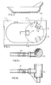
- Figure 1 is a lateral, partly sectional view of a dispenser on which a container of detergent is mounted; the detergent being in a powder, granular or pellet form;
- Figure 2 is a view similar to Figure 1 but showing a container for detergent in a solid, block form;
- Figure 3 is a sectional view of a preferred form of mesh to be used in the dispenser of Figures 1 and 2;
- Figure 4 is a plan view of the support shown in Figure 1, and
- Figures 5a and 5b are top and side views of a detail of the dispenser of Figure 2.
- The dispenser shown in Fig. 1 comprises a support 1 on which is mounted a
container 2 of the detergent. The dispenser comprises awater inlet 3 and means 4 to inject water substantially horizontally into thecontainer 2. - The means to inject the water comprises a
jet tube 5 which passes through the wall of the support 1. Between thejet tube 5 and thewater inlet 3 is fitted, in this particular embodiment, a solenoid. The solenoid valve 6 controls the supply of water to the jet tube so that detergent is dispensed only when required. In an alternative embodiment (not illustrated) the solenoid valve and electrical circuit could be omitted and the system could simply make use of the water power that is available at certain times in the washing cycle. The force of the water jet being injected via thejet tube 5 is controlled by an adjusting screw 7, discussed below. - On the support 1, and above the dispenser, is mounted a
container 2. When mounted on the support 1, thehead portion 8 of the container forms the base of the container. An aperture 9 in the side of thebase 8 allows the water to pass across the base of the container. - The detergent in granular, powder or pellet form falls by gravity to the base of the
container 2 and, when the valve allows water to be injected into the container, the detergent is washed, partly dissolved, by the water through amesh 10 at the bottom of thehead portion 8, and into anoutlet 11 leading to the washing machine (not shown). - For granular feeding, the preferred embodiment of the
mesh 10 is a louvre, as seen in Fig. 3, with the upper leading edges orientated towards the jet or jets. The granulometry of the detergent product is carefully controlled so that in the dry state the granulated product rests on the louvre and will not flow through it under its own weight. When water flows from the jet or jets the passage of water through the louvres entrains the granulated products and this resulting mixture is transported through the louvres into theoutlet 11. In typical applications the average particle size could be 500 microns and the aperture between louvres 1.5mm. - Water is intermittently injected into the container, controlled by the valve 6, until the detergent is all used up. When this happens, a new container full of detergent must be mounted onto the dispenser. However, at this point, the valve may be allowing water to be injected from the
jet tube 5. In conventional systems, the water would be sprayed upwardly which is very dangerous as the water can be either very hot or can contain dangerous chemicals, or both. Conventional devices need to include some mechanism to prevent the spray of water injuring users. - However, with the present invention, as the water passes horizontally in the dispenser, no dangerous jet of water can spray out onto the user.
- If the washing machine is shut down, for example at a week end, it is inevitable that some of the detergent not yet washed into the machine has been wetted to a certain extent. This detergent will be at the base of the container. With the conventional systems where a vertical jet of water is used, the depth of the wetted detergent is relatively great. This wetted portion of detergent tends to harden while the dispenser is not is used and so when the dispenser is next used, detergent is not dispensed efficiently.
- In the described embodiment, when the dispenser is started up again, the horizontal jet will wash away hardened material at the very base of the container. Further, when the material at the very base has been washed away, the horizontal jet of water will reach a
deflector 13 on the opposite side to the head portion of the container from the aperture 9. Thedeflector 13 deflects water in a generally upward direction. Thedeflector 13 is also shaped to spread out the jet of water into a sheet so that the water covers the entire base of the container. This sheet of water soon cuts through any hardened detergent at the base of the container. When the hardened detergent is cleared away, the dry detergent can fall as before and the dispenser then works normally again. It should be emphasized that this switch from the clearing away operation to the normal operation occurs automatically in the described embodiment. - The dispenser as illustrated is preferably an integral wall mounted unit in which is housed the
jet tube 5, the valve 6 and the adjusting screw 7. As mostly clearly seen in Fig. 4, the support 1 comprises a generallycircular recess 14 into which the correspondingly shaped head of the container fits, resting on threeseats 31. Anoverflow device 12 is situated in therecess 14 to prevent contamination of the water supply shouldoutlet 11 become blocked. The size and position of the overflow are such that with theoutlet 11 completely blocked and the solenoid valve 6 open continuously an air gap of at least 40 mm is maintained between the bottom of thejet tube 5 and the water surface. The overflow may also be protected by aweir 19 to prevent it from becoming blocked. - The dispenser also has an inclined
portion 15 supporting a correspondingly shapedinclined shoulder 16 of the container. The angle of the inclined portion should be greater than the critical angle at which the powder or granular material can rest under gravity on the shoulder, without falling to the base. The container also comprises ahandle 18 and finger grips 17 for ease of insertion onto the dispenser. As mentioned above, thewater jet 5 is fitted through the circular wall of the support. - Before a container is mounted on the dispenser, its head portion is covered by a removable cap, for example a snap-fastening cap. This cap covers the
mesh 10 and the aperture 9. Before the container is used, the aperture 9 and themesh 10 are also protected by a covering of water soluble paper, which is positioned preferably below the mesh to promote rapid dissolving of the paper without wetting of the detergent on initial start-up. When the cap is removed prior to the container being mounted on the dispenser, the paper prevents the powdered detergent from escaping from the container. However, as soon as water is injected into the container, the paper dissolves and the detergent is efficiently dispensed. - In the embodiment illustrated in Fig. 1, only one
jet tube 5 is shown. While a single jet tube will work efficiently, if desired more than one tube could be arranged for inserting several jets of water around the base of the container. Alternatively, conduit means could be arranged around the base to funnel water from a single jet to be inserted through several apertures in the head portion of the container. - In the embodiment described above, it has been assumed that the container comprises detergent in a granular, powder or pellet form which will fall by gravity to the base of the container where the water is injected. However, in the embodiment of Fig. 2, it is assumed that the container comprises a detergent in a solid block form. In this embodiment, the dispenser itself is substantially the same as that in Fig. 1., except that an additional element has been added. This element, more clearly seen in Fig. 5. comprises a
cup device 20 with aninlet pipe 24 fitted on the end of thejet tube 5. Thepipe 24 connects tangentially with thecup 20 and so the water jet is directed in a circular manner around the cup. This head portion of the container for the solid detergent has a recess 25 which accommodates thecup 20 and contains anozzle device 21 which, when the container is mounted on the dispenser, fits tightly into thecup 20. The nozzle device is generally cylindrical and has asmall aperture 26 in its base. The water injected into thecup 20 is forced out through this aperture and this results in a generally conical spray of water being injected upwardly into the container to wash down the solid detergent. The container again has themesh 10 as in the previous embodiment. - When the container is removed, water simply bubbles over the edge of the
cup 20, in a controlled and safe manner. - The control of the water jet by the adjusting screw 7 will now be discussed. Due to gravity, it is obvious that the jet of water will fall as it leaves the
jet tube 5. The extent to which the jet falls is dependent upon the water pressure. lt is desired that the jet of water always hits the same point on thedeflector 13, what ever the water pressure. Accordingly, when a dispenser is first installed, the jet of water is aimed at a target on the deflector. By means of the adjusting screw 7, the jet of water is either raised or lowered. - It should also be explained that the water jet need not be perfectly horizontal for the advantages of the invention to be obtained. Provided that the injection of water has a significant radial component compared to its vertical component, the invention will operate. Of course, the radial component must be sufficient for the jet of water to travel from one side of the head portion of the container to the other, without simply falling through the mesh.
- For example, if the internal diameter of the
jet tube 5 in Fig. 1 is 3.5 mm, the distance from the end of the jet tube to thedeflector 13 is 76 mm and the flow rate 1.3 litres/min., then it can be calculated that thejet tube 5 discharge will have to be inclined upwards at 2.3° in order that the water jet passes through the centre of the aperture 9 and impacts on thedeflector 13 in the centre of its lower slope.
Claims (15)
Priority Applications (1)
| Application Number | Priority Date | Filing Date | Title |
|---|---|---|---|
| AT88306773T ATE89705T1 (en) | 1987-07-23 | 1988-07-22 | DONOR. |
Applications Claiming Priority (2)
| Application Number | Priority Date | Filing Date | Title |
|---|---|---|---|
| GB8717407 | 1987-07-23 | ||
| GB878717407A GB8717407D0 (en) | 1987-07-23 | 1987-07-23 | Dispenser |
Publications (3)
| Publication Number | Publication Date |
|---|---|
| EP0300819A2 true EP0300819A2 (en) | 1989-01-25 |
| EP0300819A3 EP0300819A3 (en) | 1989-12-20 |
| EP0300819B1 EP0300819B1 (en) | 1993-05-26 |
Family
ID=10621146
Family Applications (1)
| Application Number | Title | Priority Date | Filing Date |
|---|---|---|---|
| EP88306773A Expired - Lifetime EP0300819B1 (en) | 1987-07-23 | 1988-07-22 | Dispenser |
Country Status (10)
| Country | Link |
|---|---|
| US (1) | US5147615A (en) |
| EP (1) | EP0300819B1 (en) |
| AT (1) | ATE89705T1 (en) |
| AU (1) | AU609498B2 (en) |
| CA (1) | CA1320837C (en) |
| DE (1) | DE3881293T2 (en) |
| DK (1) | DK169808B1 (en) |
| ES (1) | ES2041314T3 (en) |
| GB (1) | GB8717407D0 (en) |
| NZ (1) | NZ225490A (en) |
Cited By (18)
| Publication number | Priority date | Publication date | Assignee | Title |
|---|---|---|---|---|
| FR2620924A1 (en) * | 1987-09-25 | 1989-03-31 | Bosch Siemens Hausgeraete | HOUSEHOLD DISHWASHER CONTROLS BY PROGRAM |
| US4982877A (en) * | 1987-04-22 | 1991-01-08 | Burton John W | Replaceable container for fluid dispenser |
| WO1991002684A1 (en) * | 1989-08-23 | 1991-03-07 | Gibson Chemicals Limited | Dispensing apparatus |
| US5167350A (en) * | 1988-05-02 | 1992-12-01 | Henkel Kommanditgesellschaft Aut Aktien | Detergent dispensing device |
| WO1993007798A1 (en) * | 1991-10-25 | 1993-04-29 | Diversey Corporation | Detergent dispensing system |
| AU636381B2 (en) * | 1989-08-23 | 1993-04-29 | Gibson Chemicals Limited | Dispensing apparatus |
| US5229084A (en) * | 1992-03-25 | 1993-07-20 | Beta Technology, Inc. | Dispenser cap with distributor for non-liquid chemical delivery systems |
| US5262132A (en) * | 1990-04-30 | 1993-11-16 | Diversey Corporation | Solid detergent dispensing system |
| WO1995007976A2 (en) * | 1993-09-13 | 1995-03-23 | Diversey Corporation | Tableted detergent, method of manufacture and use |
| WO1995010216A1 (en) * | 1993-10-13 | 1995-04-20 | Ecolab Inc. | Clinic sink system including solid chemical product dispenser and method |
| WO1996041565A1 (en) * | 1995-06-12 | 1996-12-27 | Unilever N.V. | Flexible walled container for tableted or pelleted ware washing detergents |
| WO1997029676A1 (en) * | 1996-02-19 | 1997-08-21 | Unilever N.V. | Dispenser |
| EP0862890A1 (en) * | 1997-03-06 | 1998-09-09 | CHEMISCHE FABRIK DR. WEIGERT (GMBH & CO.) | Powder dosing device |
| WO1998052864A1 (en) * | 1997-05-17 | 1998-11-26 | Henkel-Ecolab Gmbh & Co. Ohg | Dual-chamber canister for producing diluted ready-to-use solutions with anti-confusion protection |
| WO2000030971A1 (en) * | 1998-11-26 | 2000-06-02 | Henkel Ecolab Gmbh & Co Ohg | Device for filling automatic machines with a chemical solution |
| US9022642B2 (en) | 2011-04-28 | 2015-05-05 | Hubert Ray Broome | Dissolution generator, method of dissolving powder, and mixing system |
| EP1747428B1 (en) * | 2004-05-06 | 2019-06-12 | Diversey, Inc. | Metering and dispensing closure |
| US11058999B1 (en) | 2017-07-10 | 2021-07-13 | Hubert R. Broome | Rapid dissolution generator system and method for producing same |
Families Citing this family (42)
| Publication number | Priority date | Publication date | Assignee | Title |
|---|---|---|---|---|
| US5342587A (en) * | 1992-09-24 | 1994-08-30 | Sunburst Chemicals, Inc. | Detergent dispenser for use with solid cast detergent |
| US5478537A (en) * | 1992-09-24 | 1995-12-26 | Sunburst Chemicals, Inc. | Detergent dispenser for use with solid casting detergent |
| GB9226067D0 (en) * | 1992-12-14 | 1993-02-10 | Diversey Eng Europ | Dispenser |
| US5435451A (en) * | 1993-04-20 | 1995-07-25 | Minnesota Mining And Manufacturing Company | Bottle for containing a fluid |
| US5425404A (en) * | 1993-04-20 | 1995-06-20 | Minnesota Mining And Manufacturing Company | Gravity feed fluid dispensing system |
| US5846499A (en) * | 1996-02-27 | 1998-12-08 | Sunburst Chemicals, Inc. | Air induction bowl for use with a detergent dispenser |
| US5961845A (en) * | 1997-09-26 | 1999-10-05 | Diversey Lever, Inc. | Solid product system and method of using same |
| DE69833234T2 (en) | 1997-10-08 | 2006-08-03 | Minnesota Mining And Manufacturing Company, St. Paul | Gravity liquid dispensing valve cap |
| US6007788A (en) * | 1997-10-17 | 1999-12-28 | Diverseylever, Inc. | Injection molded container for detergents |
| US5928608A (en) * | 1998-01-08 | 1999-07-27 | Arch Chemicals Inc. | Intermittant spray system for water treatment |
| US6240953B1 (en) | 1998-04-13 | 2001-06-05 | Sunburst Chemicals, Inc. | Multiple cleaning chemical dispenser |
| US6737028B1 (en) | 1999-06-02 | 2004-05-18 | Sunburst Chemicals, Inc. | Solid cast container |
| US6223791B1 (en) | 1999-10-21 | 2001-05-01 | 3M Innovative Properties Company | Gravity feed fluid dispensing valve |
| US6450214B1 (en) | 2001-08-31 | 2002-09-17 | 3M Innovative Properties Company | Gravity feed fluid dispensing valve |
| US20040020723A1 (en) * | 2002-05-10 | 2004-02-05 | Schuman Allan L. | Method and system of providing a product in a refillable container and a refillable container |
| US7216395B2 (en) * | 2002-08-01 | 2007-05-15 | Johnsondiversey, Inc. | Mop and pad washing machine |
| US6996869B2 (en) * | 2002-11-25 | 2006-02-14 | Ecolab, Inc. | Dispensing cartridge and method of dispensing a product from a dispensing cartridge |
| US6819977B2 (en) * | 2002-12-24 | 2004-11-16 | Ecolab Inc. | Dispenser having multiple modes of operation |
| US20040245279A1 (en) * | 2003-05-05 | 2004-12-09 | Bradley Tareasa L. | System for dispensing an active ingredient using a dispensable tablet, dispensable tablet and container for holding such dispensable tablets |
| US7201290B2 (en) | 2003-05-12 | 2007-04-10 | Ecolab Inc. | Method and apparatus for mass based dispensing |
| US20040226959A1 (en) | 2003-05-12 | 2004-11-18 | Mehus Richard J. | Methods of dispensing |
| US6991131B2 (en) * | 2003-09-02 | 2006-01-31 | Ecolab, Inc. | Distributable container and system and method using distributable container |
| CN100370072C (en) * | 2003-10-14 | 2008-02-20 | 杭州神林电子有限公司 | Apparatus for feeding liquid detergent |
| US20050096956A1 (en) * | 2003-10-30 | 2005-05-05 | Young David B. | Methods and systems of cleaning wares |
| US7896195B2 (en) * | 2004-06-08 | 2011-03-01 | Ecolab Inc. | Tablet dispenser with isolated product hopper |
| WO2006000237A1 (en) | 2004-06-23 | 2006-01-05 | Ecolab Inc. | Method for multiple dosage of liquid products, dosing appartus and dosing system |
| US7803321B2 (en) | 2005-03-18 | 2010-09-28 | Ecolab Inc. | Formulating chemical solutions based on volumetric and weight based control measurements |
| US8277745B2 (en) | 2007-05-02 | 2012-10-02 | Ecolab Inc. | Interchangeable load cell assemblies |
| US7694589B2 (en) | 2007-12-12 | 2010-04-13 | Ecolab Inc. | Low and empty product detection using load cell and load cell bracket |
| US20100226835A1 (en) | 2009-03-03 | 2010-09-09 | Ecolab Inc. | Method and apparatus for dispensing solid product |
| USRE48951E1 (en) | 2015-08-05 | 2022-03-01 | Ecolab Usa Inc. | Hand hygiene compliance monitoring |
| US9102509B2 (en) | 2009-09-25 | 2015-08-11 | Ecolab Inc. | Make-up dispense in a mass based dispensing system |
| US9051163B2 (en) | 2009-10-06 | 2015-06-09 | Ecolab Inc. | Automatic calibration of chemical product dispense systems |
| CN102051792B (en) * | 2009-11-03 | 2012-02-15 | 杭州神林电子有限公司 | Liquid detergent feeding device |
| US8511512B2 (en) | 2010-01-07 | 2013-08-20 | Ecolab Usa Inc. | Impact load protection for mass-based product dispensers |
| US9399198B2 (en) | 2012-10-12 | 2016-07-26 | Sunburst Chemicals, Inc. | Venturi ejector for a chemical dispenser |
| US8944286B2 (en) | 2012-11-27 | 2015-02-03 | Ecolab Usa Inc. | Mass-based dispensing using optical displacement measurement |
| CN108290171B (en) | 2015-09-21 | 2022-07-01 | 约翰逊父子公司 | System for mixing and dispensing |
| BR112019018376B1 (en) | 2017-03-07 | 2024-02-20 | Ecolab Usa Inc | DEVICE, AND, DISPENSER SIGNALING MODULE |
| US10529219B2 (en) | 2017-11-10 | 2020-01-07 | Ecolab Usa Inc. | Hand hygiene compliance monitoring |
| CN112105449B (en) | 2018-05-07 | 2023-08-22 | 埃科莱布美国股份有限公司 | Dispenser and method of dispensing a solution |
| EP3900307A1 (en) | 2018-12-20 | 2021-10-27 | Ecolab USA, Inc. | Adaptive route, bi-directional network communication |
Citations (6)
| Publication number | Priority date | Publication date | Assignee | Title |
|---|---|---|---|---|
| US2288791A (en) * | 1942-07-07 | Dispenser | ||
| US2317548A (en) * | 1940-05-15 | 1943-04-27 | Bois Soap Company Du | Detergent dispenser |
| US3416897A (en) * | 1965-10-19 | 1968-12-17 | Olin Mathieson | Chemical dissolver for feeding a solution |
| US4020865A (en) * | 1975-10-03 | 1977-05-03 | Economics Laboratory, Inc. | Remote powder detergent dispenser |
| EP0156057A2 (en) * | 1984-03-22 | 1985-10-02 | Economics Laboratory, Inc. | Solid cast detergent dispenser with insert for holding noncompatible chemicals |
| US4666682A (en) * | 1985-11-25 | 1987-05-19 | James L. Mayer | Dispenser for solid and powered detergent |
Family Cites Families (8)
| Publication number | Priority date | Publication date | Assignee | Title |
|---|---|---|---|---|
| US1510062A (en) * | 1922-09-20 | 1924-09-30 | James F Kenney | Washing device |
| US1910235A (en) * | 1930-11-14 | 1933-05-23 | Laura Burkett | Dishwashing nozzle |
| US2387945A (en) * | 1944-07-29 | 1945-10-30 | Antiseptol Company Inc | Dispensing apparatus |
| US2601672A (en) * | 1949-08-20 | 1952-06-24 | Francis L Gatchet | Fertilizer dissolving and spraying device |
| US2604386A (en) * | 1950-12-19 | 1952-07-22 | Clayton Manufacturing Co | Detergent dissolving apparatus |
| US4426362A (en) * | 1978-12-05 | 1984-01-17 | Economics Laboratory, Inc. | Solid block detergent dispenser |
| US4250911A (en) * | 1979-09-28 | 1981-02-17 | Kratz David W | Chemical feeder with disposable chemical container |
| US4759907A (en) * | 1986-10-31 | 1988-07-26 | Eltech Systems Corporation | Feeder device and method for adding solid material to a liquid of variable flow rate |
-
1987
- 1987-07-23 GB GB878717407A patent/GB8717407D0/en active Pending
-
1988
- 1988-07-18 CA CA000572322A patent/CA1320837C/en not_active Expired - Fee Related
- 1988-07-20 NZ NZ225490A patent/NZ225490A/en unknown
- 1988-07-20 US US07/221,890 patent/US5147615A/en not_active Expired - Lifetime
- 1988-07-21 AU AU19257/88A patent/AU609498B2/en not_active Ceased
- 1988-07-22 AT AT88306773T patent/ATE89705T1/en not_active IP Right Cessation
- 1988-07-22 DK DK411688A patent/DK169808B1/en not_active IP Right Cessation
- 1988-07-22 EP EP88306773A patent/EP0300819B1/en not_active Expired - Lifetime
- 1988-07-22 DE DE88306773T patent/DE3881293T2/en not_active Expired - Fee Related
- 1988-07-22 ES ES198888306773T patent/ES2041314T3/en not_active Expired - Lifetime
Patent Citations (6)
| Publication number | Priority date | Publication date | Assignee | Title |
|---|---|---|---|---|
| US2288791A (en) * | 1942-07-07 | Dispenser | ||
| US2317548A (en) * | 1940-05-15 | 1943-04-27 | Bois Soap Company Du | Detergent dispenser |
| US3416897A (en) * | 1965-10-19 | 1968-12-17 | Olin Mathieson | Chemical dissolver for feeding a solution |
| US4020865A (en) * | 1975-10-03 | 1977-05-03 | Economics Laboratory, Inc. | Remote powder detergent dispenser |
| EP0156057A2 (en) * | 1984-03-22 | 1985-10-02 | Economics Laboratory, Inc. | Solid cast detergent dispenser with insert for holding noncompatible chemicals |
| US4666682A (en) * | 1985-11-25 | 1987-05-19 | James L. Mayer | Dispenser for solid and powered detergent |
Cited By (21)
| Publication number | Priority date | Publication date | Assignee | Title |
|---|---|---|---|---|
| US4982877A (en) * | 1987-04-22 | 1991-01-08 | Burton John W | Replaceable container for fluid dispenser |
| FR2620924A1 (en) * | 1987-09-25 | 1989-03-31 | Bosch Siemens Hausgeraete | HOUSEHOLD DISHWASHER CONTROLS BY PROGRAM |
| US5167350A (en) * | 1988-05-02 | 1992-12-01 | Henkel Kommanditgesellschaft Aut Aktien | Detergent dispensing device |
| WO1991002684A1 (en) * | 1989-08-23 | 1991-03-07 | Gibson Chemicals Limited | Dispensing apparatus |
| AU636381B2 (en) * | 1989-08-23 | 1993-04-29 | Gibson Chemicals Limited | Dispensing apparatus |
| US5262132A (en) * | 1990-04-30 | 1993-11-16 | Diversey Corporation | Solid detergent dispensing system |
| WO1993007798A1 (en) * | 1991-10-25 | 1993-04-29 | Diversey Corporation | Detergent dispensing system |
| US5229084A (en) * | 1992-03-25 | 1993-07-20 | Beta Technology, Inc. | Dispenser cap with distributor for non-liquid chemical delivery systems |
| WO1995007976A3 (en) * | 1993-09-13 | 1995-06-01 | Diversey Corp | Tableted detergent, method of manufacture and use |
| WO1995007976A2 (en) * | 1993-09-13 | 1995-03-23 | Diversey Corporation | Tableted detergent, method of manufacture and use |
| US5713384A (en) * | 1993-09-13 | 1998-02-03 | Unilever N.V. | Tableted detergent, method of manufacture and use |
| WO1995010216A1 (en) * | 1993-10-13 | 1995-04-20 | Ecolab Inc. | Clinic sink system including solid chemical product dispenser and method |
| WO1996041565A1 (en) * | 1995-06-12 | 1996-12-27 | Unilever N.V. | Flexible walled container for tableted or pelleted ware washing detergents |
| WO1997029676A1 (en) * | 1996-02-19 | 1997-08-21 | Unilever N.V. | Dispenser |
| US5827486A (en) * | 1996-02-19 | 1998-10-27 | Diversey Lever, Inc. | Dispenser |
| EP0862890A1 (en) * | 1997-03-06 | 1998-09-09 | CHEMISCHE FABRIK DR. WEIGERT (GMBH & CO.) | Powder dosing device |
| WO1998052864A1 (en) * | 1997-05-17 | 1998-11-26 | Henkel-Ecolab Gmbh & Co. Ohg | Dual-chamber canister for producing diluted ready-to-use solutions with anti-confusion protection |
| WO2000030971A1 (en) * | 1998-11-26 | 2000-06-02 | Henkel Ecolab Gmbh & Co Ohg | Device for filling automatic machines with a chemical solution |
| EP1747428B1 (en) * | 2004-05-06 | 2019-06-12 | Diversey, Inc. | Metering and dispensing closure |
| US9022642B2 (en) | 2011-04-28 | 2015-05-05 | Hubert Ray Broome | Dissolution generator, method of dissolving powder, and mixing system |
| US11058999B1 (en) | 2017-07-10 | 2021-07-13 | Hubert R. Broome | Rapid dissolution generator system and method for producing same |
Also Published As
| Publication number | Publication date |
|---|---|
| EP0300819A3 (en) | 1989-12-20 |
| AU1925788A (en) | 1989-02-09 |
| DK411688A (en) | 1989-01-24 |
| AU609498B2 (en) | 1991-05-02 |
| ATE89705T1 (en) | 1993-06-15 |
| DK411688D0 (en) | 1988-07-22 |
| GB8717407D0 (en) | 1987-08-26 |
| NZ225490A (en) | 1990-12-21 |
| US5147615A (en) | 1992-09-15 |
| DE3881293T2 (en) | 1993-11-04 |
| ES2041314T3 (en) | 1993-11-16 |
| DE3881293D1 (en) | 1993-07-01 |
| DK169808B1 (en) | 1995-03-06 |
| CA1320837C (en) | 1993-08-03 |
| EP0300819B1 (en) | 1993-05-26 |
Similar Documents
| Publication | Publication Date | Title |
|---|---|---|
| US5147615A (en) | Method of dispensing and dispenser therefor | |
| CA2243362C (en) | Dispenser | |
| US4790981A (en) | Dispenser for solid and powdered detergent | |
| US7150219B2 (en) | Filter cup for coffee machine and coffee-making process | |
| US5411716A (en) | Solid detergent dispenser for floor scrubber machine | |
| US5505915A (en) | Solid chemical dispenser with movable nozzle | |
| AU2016297089B2 (en) | Solid product dispenser for small volume applications | |
| EP0058507B1 (en) | Powder dispenser | |
| KR0135677B1 (en) | A detergent melting apparatus | |
| JPS6233918B2 (en) | ||
| US4666682A (en) | Dispenser for solid and powered detergent | |
| EP3897338A1 (en) | Dishwasher with detergent dispenser | |
| SE467190B (en) | DEVICE FOR DISPOSAL OF WATER SOLUBLE POWDER | |
| JPH09173271A (en) | Container for automatic supply of powdery detergent | |
| JPH09276202A (en) | Washing solution supply device, container for storing detergent, and cap | |
| SE467191B (en) | Device for dissolving water-soluble powder | |
| SE467192B (en) | DEVICE FOR DISPOSAL OF WATER SOLUBLE POWDER |
Legal Events
| Date | Code | Title | Description |
|---|---|---|---|
| PUAI | Public reference made under article 153(3) epc to a published international application that has entered the european phase |
Free format text: ORIGINAL CODE: 0009012 |
|
| AK | Designated contracting states |
Kind code of ref document: A2 Designated state(s): AT BE DE ES FR GB IT NL SE |
|
| PUAL | Search report despatched |
Free format text: ORIGINAL CODE: 0009013 |
|
| AK | Designated contracting states |
Kind code of ref document: A3 Designated state(s): AT BE DE ES FR GB IT NL SE |
|
| RHK1 | Main classification (correction) |
Ipc: A47L 15/44 |
|
| 17P | Request for examination filed |
Effective date: 19900308 |
|
| 17Q | First examination report despatched |
Effective date: 19920220 |
|
| GRAA | (expected) grant |
Free format text: ORIGINAL CODE: 0009210 |
|
| AK | Designated contracting states |
Kind code of ref document: B1 Designated state(s): AT BE DE ES FR GB IT NL SE |
|
| REF | Corresponds to: |
Ref document number: 89705 Country of ref document: AT Date of ref document: 19930615 Kind code of ref document: T |
|
| REF | Corresponds to: |
Ref document number: 3881293 Country of ref document: DE Date of ref document: 19930701 |
|
| ET | Fr: translation filed | ||
| ITF | It: translation for a ep patent filed |
Owner name: SOCIETA' ITALIANA BREVETTI S.P.A. |
|
| RAP2 | Party data changed (patent owner data changed or rights of a patent transferred) |
Owner name: DIVERSEY CORPORATION |
|
| REG | Reference to a national code |
Ref country code: ES Ref legal event code: FG2A Ref document number: 2041314 Country of ref document: ES Kind code of ref document: T3 |
|
| PLBE | No opposition filed within time limit |
Free format text: ORIGINAL CODE: 0009261 |
|
| STAA | Information on the status of an ep patent application or granted ep patent |
Free format text: STATUS: NO OPPOSITION FILED WITHIN TIME LIMIT |
|
| 26N | No opposition filed | ||
| EAL | Se: european patent in force in sweden |
Ref document number: 88306773.8 |
|
| BECA | Be: change of holder's address |
Free format text: 20011206 *UNILEVER N.V.:WEENA 455, 3013 AL ROTTERDAM |
|
| REG | Reference to a national code |
Ref country code: GB Ref legal event code: IF02 |
|
| NLS | Nl: assignments of ep-patents |
Owner name: UNILEVER N.V. |
|
| REG | Reference to a national code |
Ref country code: FR Ref legal event code: TP |
|
| REG | Reference to a national code |
Ref country code: FR Ref legal event code: TP |
|
| REG | Reference to a national code |
Ref country code: GB Ref legal event code: 732E |
|
| NLS | Nl: assignments of ep-patents |
Owner name: DIVERSEY IP INTERNATIONAL BV |
|
| REG | Reference to a national code |
Ref country code: FR Ref legal event code: TP |
|
| REG | Reference to a national code |
Ref country code: GB Ref legal event code: 732E |
|
| PGFP | Annual fee paid to national office [announced via postgrant information from national office to epo] |
Ref country code: NL Payment date: 20030703 Year of fee payment: 16 Ref country code: AT Payment date: 20030703 Year of fee payment: 16 |
|
| PGFP | Annual fee paid to national office [announced via postgrant information from national office to epo] |
Ref country code: GB Payment date: 20030716 Year of fee payment: 16 |
|
| PGFP | Annual fee paid to national office [announced via postgrant information from national office to epo] |
Ref country code: FR Payment date: 20030718 Year of fee payment: 16 |
|
| PGFP | Annual fee paid to national office [announced via postgrant information from national office to epo] |
Ref country code: SE Payment date: 20030721 Year of fee payment: 16 |
|
| PGFP | Annual fee paid to national office [announced via postgrant information from national office to epo] |
Ref country code: DE Payment date: 20030731 Year of fee payment: 16 |
|
| PGFP | Annual fee paid to national office [announced via postgrant information from national office to epo] |
Ref country code: ES Payment date: 20030807 Year of fee payment: 16 |
|
| PGFP | Annual fee paid to national office [announced via postgrant information from national office to epo] |
Ref country code: BE Payment date: 20030821 Year of fee payment: 16 |
|
| PG25 | Lapsed in a contracting state [announced via postgrant information from national office to epo] |
Ref country code: GB Free format text: LAPSE BECAUSE OF NON-PAYMENT OF DUE FEES Effective date: 20040722 Ref country code: AT Free format text: LAPSE BECAUSE OF NON-PAYMENT OF DUE FEES Effective date: 20040722 |
|
| PG25 | Lapsed in a contracting state [announced via postgrant information from national office to epo] |
Ref country code: SE Free format text: LAPSE BECAUSE OF NON-PAYMENT OF DUE FEES Effective date: 20040723 Ref country code: ES Free format text: LAPSE BECAUSE OF NON-PAYMENT OF DUE FEES Effective date: 20040723 |
|
| PG25 | Lapsed in a contracting state [announced via postgrant information from national office to epo] |
Ref country code: BE Free format text: LAPSE BECAUSE OF NON-PAYMENT OF DUE FEES Effective date: 20040731 |
|
| BERE | Be: lapsed |
Owner name: *DIVERSEY IP INTERNATIONAL BV Effective date: 20040731 |
|
| PG25 | Lapsed in a contracting state [announced via postgrant information from national office to epo] |
Ref country code: NL Free format text: LAPSE BECAUSE OF NON-PAYMENT OF DUE FEES Effective date: 20050201 Ref country code: DE Free format text: LAPSE BECAUSE OF NON-PAYMENT OF DUE FEES Effective date: 20050201 |
|
| EUG | Se: european patent has lapsed | ||
| GBPC | Gb: european patent ceased through non-payment of renewal fee |
Effective date: 20040722 |
|
| PG25 | Lapsed in a contracting state [announced via postgrant information from national office to epo] |
Ref country code: FR Free format text: LAPSE BECAUSE OF NON-PAYMENT OF DUE FEES Effective date: 20050331 |
|
| NLV4 | Nl: lapsed or anulled due to non-payment of the annual fee |
Effective date: 20050201 |
|
| REG | Reference to a national code |
Ref country code: FR Ref legal event code: ST |
|
| PG25 | Lapsed in a contracting state [announced via postgrant information from national office to epo] |
Ref country code: IT Free format text: LAPSE BECAUSE OF NON-PAYMENT OF DUE FEES Effective date: 20050722 |
|
| REG | Reference to a national code |
Ref country code: ES Ref legal event code: FD2A Effective date: 20040723 |
|
| BERE | Be: lapsed |
Owner name: *DIVERSEY IP INTERNATIONAL BV Effective date: 20040731 |