EP0301573A2 - Registration of a new cordless telephone to an existing system - Google Patents
Registration of a new cordless telephone to an existing system Download PDFInfo
- Publication number
- EP0301573A2 EP0301573A2 EP88112328A EP88112328A EP0301573A2 EP 0301573 A2 EP0301573 A2 EP 0301573A2 EP 88112328 A EP88112328 A EP 88112328A EP 88112328 A EP88112328 A EP 88112328A EP 0301573 A2 EP0301573 A2 EP 0301573A2
- Authority
- EP
- European Patent Office
- Prior art keywords
- telephone
- identification number
- cordless telephone
- cordless
- access unit
- Prior art date
- Legal status (The legal status is an assumption and is not a legal conclusion. Google has not performed a legal analysis and makes no representation as to the accuracy of the status listed.)
- Granted
Links
- 230000015654 memory Effects 0.000 claims abstract description 25
- 230000004044 response Effects 0.000 claims abstract description 6
- 238000012795 verification Methods 0.000 claims abstract description 4
- 238000000034 method Methods 0.000 claims description 6
- 238000010586 diagram Methods 0.000 description 4
- 238000004519 manufacturing process Methods 0.000 description 3
- 230000003213 activating effect Effects 0.000 description 1
- 230000000994 depressogenic effect Effects 0.000 description 1
- 238000009434 installation Methods 0.000 description 1
- 238000012986 modification Methods 0.000 description 1
- 230000004048 modification Effects 0.000 description 1
- 230000000717 retained effect Effects 0.000 description 1
- 230000011664 signaling Effects 0.000 description 1
Images


Classifications
-
- H—ELECTRICITY
- H04—ELECTRIC COMMUNICATION TECHNIQUE
- H04M—TELEPHONIC COMMUNICATION
- H04M1/00—Substation equipment, e.g. for use by subscribers
- H04M1/72—Mobile telephones; Cordless telephones, i.e. devices for establishing wireless links to base stations without route selection
- H04M1/725—Cordless telephones
- H04M1/727—Identification code transfer arrangements
Definitions
- the present invention relates generally to cordless telephone systems which are connected to a switched telephone network and, in particular, to registration of a new cordless telephone to an existing cordless telephone system.
- Cordless telephone systems comprise an access unit which is connected through a subscriber loop to a switched telephone network and a plurality of cordless telephones.
- a two-way radio channel is established between the access unit and each cordless telephone by transmitting the system identification number of the system from a transmit end and verifying at a receive end that the transmitted system identification number is identical to that of the own system. This verification operation is necessary to avoid interference which might occur between cordless telephone systems which cover adjacent service areas.
- a system identification number is assigned to each system at the shipment from the factory by storing such number into the read-only memory of the access unit and into the read-only memory of each of the associated cordless telephones.
- the present invention is based on the utilization of a product identification, or "serial" number which is uniquely assigned to each cordless telephone at the stage of manufacture and the utilization of a memory of the type which allows data to be electrically written and permanently stored.
- a product identification, or "serial" number which is uniquely assigned to each cordless telephone at the stage of manufacture
- a memory of the type which allows data to be electrically written and permanently stored.
- a typical example of such a memory is the electrically erasable programmable read-only memory, or EEPROM.
- a new cordless telephone is registered to an existing cordless telephone system by transmitting the product identification number of the new cordless telephone from the access unit of the system of the new cordless telephone, receiving the transmitted product identification number at the new cordless telephone and verifying that the transmitted product identification number is correctly received.
- the system and telephone identification numbers of the new cordless telephone are transmitted from the access unit and to the new cordless telephone and permanently stored into a memory of this telephone to be used for establishing calls.
- the product and telephone identification numbers of the new cordless telephone are transmitted from one of the existing cordless telephones to the access unit to be relayed to the new cordless telephone.
- a plurality of portable cordless telephones 1011 to 101 n form a cordless telephone system with a radio access unit 1 which is connected through a subscriber loop 2 to a line terminal of a switched telephone network 20.
- the cordless telephone system is assigned a unique system identification number to distinguish it from other cordless telephone systems.
- Each of the cordless telephones 101 has a product identification number which is unique to it and no other cordless telephones of the same product type have the same number and a telephone identification number which is unique to it only in the own cordless telephone system. As shown in Fig.
- access unit 1 is a main telephone of the cordless telephone system and operates as an interface for manually completing incoming calls from the telephone network 20 to one of the cordless telephones 101 with the aid of an attendant personnel in a manner similar to conventional key telephone systems and for automatically relaying dialled information of an outgoing call to the telephone network or establishing an intercom call between cordless telephones of the same system.
- Access unit 1 includes a line interface circuit 3 coupled to the telephone network 2 via the subscriber loop 2, a handset 4 coupled to the line interface circuit 3, a loop control circuit 5, a transmit/receive unit 6 which selectively establishes a two-way radio channel with any of the cordless portable telephones 101.
- a controller 7 is provided for controlling the line interface circuit 3, loop control circuit 5 and transmit/receive unit 6 in response to a ringing signal from the network 20 or in response to an off-hook signal received from the cordless telephones 101 and further in response to a signal from a talk key 8 and a numeric key pad 11 when originating an outgoing call from the access unit or forwarding an incoming call from the network to the cordless telephones.
- the system identification number is stored in a read-only memory 10, which is addressed by the controller 7 whenever an off-hook signal is received from a cordless telephone to check the stored system identification number against one sent from the cordless telephone to verify that it belongs to the own cordless telephone system.
- Each portable telephone 101 comprises a transmit/receive unit 102, a loop control circuit 103, a handset 104, a controller 105, a talk key 106, a tone ringer 107 and an electrically erasable programmable read-only memory 108 which stores the system identification number assigned at the shipment of the system from the factory, the product identification number assigned to each portable telephone at the stage of product and a telephone identification number assigned at the site of installation. The stored information is retained in a nonvolatile manner to be used for establishing calls.
- a numeric keypad 109 is also connected to the controller 105 for generating a dialling signal.
- the controller 105 of a call-originating telephone 101 checks to see if the talk key 106 is depressed (step 301) and, if it is, controller 105 retrieves the system identification number from the memory 108 and sends it to the access unit 1 as an off-hook signal through the transmit/receive unit 102 (step 302).
- the controller 7 of access unit 1 compares it with the system identification number stored in memory 10.
- controller 7 If they match (step 202), controller 7 returns the system identification number as a proceed-to-send signal (step 203) and activates the loop control circuit 5 (step 204) to form a DC loop across the subscriber line terminal. Dial tone from the telephone network can therefore be heard by the originating telephone.
- the controller 105 of the originating telephone On receiving the proceed-to-send signal (step 303), the controller 105 of the originating telephone reads the system identification number out of the memory 108 for comparison with the received system identification number. If they match (step 304), controller 105 activates the loop control circuit 103 (step 305) to connect the handset 104 to the transmit/receive unit 102 to receive the dial tone from the access unit 1 and connects the keypad 109 to the transmit/receive unit to allow the caller to operate the keypad 109 to send a dialling signal to the access unit 1 (steps 306 and 307). The dialled information is received to the access unit and relayed to the telephone network (steps 205 and 206).
- incoming calls are handled in a manner inverse to that shown above. Namely, when completing an incoming call from the access unit 1, a ringing signal is detected by the controller 105 and the tone ringer 107 is activated to urge the user to operate the talk key 106 for signalling answer of the call. Controller 105 responds to it by activating the loop control circuit 103 to couple the handset 104 to the transmit/receive unit 102 to establish a connection.
- controller 7 When installing a new cordless telephone, a servicing personnel first visits the site where it is installed and then visits the site of the access unit. The personnel enters the product identification number of the new telephone into a random access memory of the controller 7 of the access unit and assigns a unique telephone identification number and enters it into the RAM as shown in step 211 in Fig. 4a. Controller 7 then sends the product identification number to the new cordless telephone as a setup signal (step 212). On receiving the setup signal (step 311), controller 105 of the new cordless telephone checks whether the received product identification number coincides with one stored in the memory 108 (step 312). If they match, the controller 105 returns the product identification number stored in the memory 105 to the access unit as a proceed-to-send signal (step 313).
- controller 7 On receiving this signal (step 213), the controller 7 checks whether the received product identification number coincides with the previously entered number to verify that the new cordless telephone has correctly received the setup signal (step 214). If coincidence occurs, controller 7 reads the system identification number from the read-only memory 10 and the telephone identification number from the random access memory of the controller 7 and sends them as an ID registration signal to the new cordless telephone (step 215). On receiving the ID registration signal (step 314), controller 105 of the new cordless telephone stores the received system identification number and the telephone identification number into the electrically erasable PROM 108 (step 315).
- the servicing personnel may visit the site of an existing cordless telephone to send a registration request signal to the access unit 1.
- the servicing personnel first enters the product identification number of the new cordless telephone into a random access memory of the controller 105 of the existing telephone using its numeric keypad 109 and then enters the system identification number and a newly assigned telephone identification number (step 401).
- Controller 105 of the existing telephone now sends the entered numbers as a registration request signal to the access unit (step 402).
- controller 7 of the access unit On receiving the registration request signal (step 501), controller 7 of the access unit stores the received signal into the random access memory of the controller and proceeds to step 212 of Fig. 4a to transmit the product identification number to the new telephone as a setup signal.
Abstract
Description
- The present invention relates generally to cordless telephone systems which are connected to a switched telephone network and, in particular, to registration of a new cordless telephone to an existing cordless telephone system.
- Cordless telephone systems comprise an access unit which is connected through a subscriber loop to a switched telephone network and a plurality of cordless telephones. A two-way radio channel is established between the access unit and each cordless telephone by transmitting the system identification number of the system from a transmit end and verifying at a receive end that the transmitted system identification number is identical to that of the own system. This verification operation is necessary to avoid interference which might occur between cordless telephone systems which cover adjacent service areas. A system identification number is assigned to each system at the shipment from the factory by storing such number into the read-only memory of the access unit and into the read-only memory of each of the associated cordless telephones. When a new cordless telephone is to be added to an existing system, the new telephone must be provided with a read-only memory in which the same system identification number is stored. Such read-only memories are currently prepared by the manufacturer in advance for future system expansion or prepared by a servicing company on a per demand basis. This adds to the total manufacturing cost of the system.
- It is therefore an object of the present invention to reduce the total manufacturing cost of a cordless telephone system by eliminating the need to prepare a read-only memory for future system expansion. The present invention is based on the utilization of a product identification, or "serial" number which is uniquely assigned to each cordless telephone at the stage of manufacture and the utilization of a memory of the type which allows data to be electrically written and permanently stored. A typical example of such a memory is the electrically erasable programmable read-only memory, or EEPROM. In accordance with this invention, a new cordless telephone is registered to an existing cordless telephone system by transmitting the product identification number of the new cordless telephone from the access unit of the system of the new cordless telephone, receiving the transmitted product identification number at the new cordless telephone and verifying that the transmitted product identification number is correctly received. In response to the verification, the system and telephone identification numbers of the new cordless telephone are transmitted from the access unit and to the new cordless telephone and permanently stored into a memory of this telephone to be used for establishing calls. Alternatively, the product and telephone identification numbers of the new cordless telephone are transmitted from one of the existing cordless telephones to the access unit to be relayed to the new cordless telephone. This alternative approach eliminates the need to visit the site of the access unit by a servicing personnel by remotely controlling the access unit with the information transmitted from the existing cordless telephone.
- The present invention will be described in further detail with reference to the accompanying drawings, in which:
- Fig. 1 is a block diagram of a cordless telephone system embodying the present invention;
- Fig. 2 is an illustration of details of the system of Fig. 1;
- Figs 3a and 3b are flow diagrams of the access unit and each cordless telephone, respectively, when an outgoing call is originated from one of the cordless telephones;
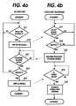
- Figs. 4a and 4b are flow diagrams of the access unit and a newly installed cordless telephone, respectively, illustrating a registration process; and
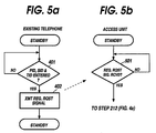
- Figs. 5a and 5b are flow diagrams of an existing cordless telephone and the access unit, respectively, illustrating a modified registration process.
- In Fig. 1, a plurality of portable cordless telephones 101₁ to 101n form a cordless telephone system with a
radio access unit 1 which is connected through a subscriber loop 2 to a line terminal of a switchedtelephone network 20. The cordless telephone system is assigned a unique system identification number to distinguish it from other cordless telephone systems. Each of thecordless telephones 101 has a product identification number which is unique to it and no other cordless telephones of the same product type have the same number and a telephone identification number which is unique to it only in the own cordless telephone system. As shown in Fig. 2,access unit 1 is a main telephone of the cordless telephone system and operates as an interface for manually completing incoming calls from thetelephone network 20 to one of thecordless telephones 101 with the aid of an attendant personnel in a manner similar to conventional key telephone systems and for automatically relaying dialled information of an outgoing call to the telephone network or establishing an intercom call between cordless telephones of the same system.Access unit 1 includes aline interface circuit 3 coupled to the telephone network 2 via the subscriber loop 2, a handset 4 coupled to theline interface circuit 3, aloop control circuit 5, a transmit/receiveunit 6 which selectively establishes a two-way radio channel with any of the cordlessportable telephones 101. Acontroller 7 is provided for controlling theline interface circuit 3,loop control circuit 5 and transmit/receiveunit 6 in response to a ringing signal from thenetwork 20 or in response to an off-hook signal received from thecordless telephones 101 and further in response to a signal from a talk key 8 and anumeric key pad 11 when originating an outgoing call from the access unit or forwarding an incoming call from the network to the cordless telephones. The system identification number is stored in a read-only memory 10, which is addressed by thecontroller 7 whenever an off-hook signal is received from a cordless telephone to check the stored system identification number against one sent from the cordless telephone to verify that it belongs to the own cordless telephone system. - Each
portable telephone 101 comprises a transmit/receiveunit 102, aloop control circuit 103, ahandset 104, acontroller 105, atalk key 106, atone ringer 107 and an electrically erasable programmable read-only memory 108 which stores the system identification number assigned at the shipment of the system from the factory, the product identification number assigned to each portable telephone at the stage of product and a telephone identification number assigned at the site of installation. The stored information is retained in a nonvolatile manner to be used for establishing calls. Anumeric keypad 109 is also connected to thecontroller 105 for generating a dialling signal. - When originating an outgoing call, the user depresses the
talk key 106. As specifically shown in Figs. 3a and 3b, thecontroller 105 of a call-originatingtelephone 101 checks to see if thetalk key 106 is depressed (step 301) and, if it is,controller 105 retrieves the system identification number from thememory 108 and sends it to theaccess unit 1 as an off-hook signal through the transmit/receive unit 102 (step 302). On receiving the off-hook signal from the cordless telephone (step 201), thecontroller 7 ofaccess unit 1 compares it with the system identification number stored inmemory 10. If they match (step 202),controller 7 returns the system identification number as a proceed-to-send signal (step 203) and activates the loop control circuit 5 (step 204) to form a DC loop across the subscriber line terminal. Dial tone from the telephone network can therefore be heard by the originating telephone. - On receiving the proceed-to-send signal (step 303), the
controller 105 of the originating telephone reads the system identification number out of thememory 108 for comparison with the received system identification number. If they match (step 304),controller 105 activates the loop control circuit 103 (step 305) to connect thehandset 104 to the transmit/receiveunit 102 to receive the dial tone from theaccess unit 1 and connects thekeypad 109 to the transmit/receive unit to allow the caller to operate thekeypad 109 to send a dialling signal to the access unit 1 (steps 306 and 307). The dialled information is received to the access unit and relayed to the telephone network (steps 205 and 206). - Although not shown in detail, incoming calls are handled in a manner inverse to that shown above. Namely, when completing an incoming call from the
access unit 1, a ringing signal is detected by thecontroller 105 and thetone ringer 107 is activated to urge the user to operate thetalk key 106 for signalling answer of the call.Controller 105 responds to it by activating theloop control circuit 103 to couple thehandset 104 to the transmit/receiveunit 102 to establish a connection. - When installing a new cordless telephone, a servicing personnel first visits the site where it is installed and then visits the site of the access unit. The personnel enters the product identification number of the new telephone into a random access memory of the
controller 7 of the access unit and assigns a unique telephone identification number and enters it into the RAM as shown instep 211 in Fig. 4a.Controller 7 then sends the product identification number to the new cordless telephone as a setup signal (step 212). On receiving the setup signal (step 311),controller 105 of the new cordless telephone checks whether the received product identification number coincides with one stored in the memory 108 (step 312). If they match, thecontroller 105 returns the product identification number stored in thememory 105 to the access unit as a proceed-to-send signal (step 313). On receiving this signal (step 213), thecontroller 7 checks whether the received product identification number coincides with the previously entered number to verify that the new cordless telephone has correctly received the setup signal (step 214). If coincidence occurs,controller 7 reads the system identification number from the read-only memory 10 and the telephone identification number from the random access memory of thecontroller 7 and sends them as an ID registration signal to the new cordless telephone (step 215). On receiving the ID registration signal (step 314),controller 105 of the new cordless telephone stores the received system identification number and the telephone identification number into the electrically erasable PROM 108 (step 315). - Instead of visiting the site of the access unit, the servicing personnel may visit the site of an existing cordless telephone to send a registration request signal to the
access unit 1. As shown in Figs. 5a and 5b, the servicing personnel first enters the product identification number of the new cordless telephone into a random access memory of thecontroller 105 of the existing telephone using itsnumeric keypad 109 and then enters the system identification number and a newly assigned telephone identification number (step 401).Controller 105 of the existing telephone now sends the entered numbers as a registration request signal to the access unit (step 402). On receiving the registration request signal (step 501),controller 7 of the access unit stores the received signal into the random access memory of the controller and proceeds tostep 212 of Fig. 4a to transmit the product identification number to the new telephone as a setup signal. - The foregoing description shows only preferred embodiments of the present invention. Various modifications are apparent to those skilled in the art without departing from the scope of the present invention which is only limited by the appended claims. Therefore, the embodiments shown and described are only illustrative, not restrictive.
Claims (6)
said access unit comprising means for transmitting said system identification number and the product and telephone identification numbers of one of said cordless telephones when same is to be registered to said system as a new telephone; and
said one cordless telephone comprising a memory of the type which allows data to be electrically written therein and means for verifying whether said product identification number transmitted from said access unit is identical to the product identification number of said one cordless telephone and writing said system and telephone identification numbers transmitted from said access unit into said memory if said product identification number is verified.
Applications Claiming Priority (4)
| Application Number | Priority Date | Filing Date | Title |
|---|---|---|---|
| JP62190117A JP2564839B2 (en) | 1987-07-31 | 1987-07-31 | Wireless telephone equipment |
| JP190117/87 | 1987-07-31 | ||
| JP287228/87 | 1987-11-16 | ||
| JP62287228A JPH0654925B2 (en) | 1987-11-16 | 1987-11-16 | Wireless telephone |
Publications (3)
| Publication Number | Publication Date |
|---|---|
| EP0301573A2 true EP0301573A2 (en) | 1989-02-01 |
| EP0301573A3 EP0301573A3 (en) | 1989-07-26 |
| EP0301573B1 EP0301573B1 (en) | 1993-04-07 |
Family
ID=26505884
Family Applications (1)
| Application Number | Title | Priority Date | Filing Date |
|---|---|---|---|
| EP88112328A Expired - Lifetime EP0301573B1 (en) | 1987-07-31 | 1988-07-29 | Registration of a new cordless telephone to an existing system |
Country Status (6)
| Country | Link |
|---|---|
| US (1) | US4864599A (en) |
| EP (1) | EP0301573B1 (en) |
| KR (1) | KR920001065B1 (en) |
| AU (1) | AU594624B2 (en) |
| DE (1) | DE3880038T2 (en) |
| HK (1) | HK143194A (en) |
Cited By (19)
| Publication number | Priority date | Publication date | Assignee | Title |
|---|---|---|---|---|
| EP0373611A2 (en) * | 1988-12-12 | 1990-06-20 | Sharp Kabushiki Kaisha | Cordless telephone |
| WO1991007856A1 (en) * | 1989-11-11 | 1991-05-30 | Gpt Limited | Cordless telephone registration method |
| EP0478231A2 (en) * | 1990-09-28 | 1992-04-01 | AT&T Corp. | Method and apparatus for remotely programming a wireless telephone set |
| EP0565528A1 (en) * | 1990-12-31 | 1993-10-20 | Motorola Inc. | Secure over-the-air registration of cordless telephones |
| US5297192A (en) * | 1990-09-28 | 1994-03-22 | At&T Bell Laboratories | Method and apparatus for remotely programming a mobile data telephone set |
| US5297191A (en) * | 1990-09-28 | 1994-03-22 | At&T Bell Laboratories | Method and apparatus for remotely programming a wireless telephone set |
| WO1994010785A1 (en) * | 1992-10-30 | 1994-05-11 | Siemens Aktiengesellschaft | Process for combining transmitter-receiver pairs of a cordless communications system to form a communicating unit |
| WO1994010784A1 (en) * | 1992-10-30 | 1994-05-11 | Siemens Aktiengesellschaft | Process for managing a multitude of mobile stations that are registered in a base station in a cordless communications system |
| US5485505A (en) * | 1993-11-23 | 1996-01-16 | Bellsouth Corporation | Apparatus and method for remotely initiating operation of a cellular telephone |
| EP0746955A1 (en) * | 1994-02-24 | 1996-12-11 | Gte Mobile Communications Service Corporation | Cellular radiotelephone system with remotely programmed mobile stations |
| WO1997044966A1 (en) * | 1996-05-20 | 1997-11-27 | Siemens Aktiengesellschaft | Method for coupling of telecommunication terminals to a radio network termination |
| EP0844776A1 (en) * | 1996-11-22 | 1998-05-27 | Koninklijke Philips Electronics N.V. | Validation procedure of a cordless telephone to the base station |
| WO1999031859A1 (en) * | 1997-12-12 | 1999-06-24 | Thomson Consumer Electronics, Inc. | Initialization of handsets in a multi-line wireless phone system for secure communications |
| US6192231B1 (en) | 1996-07-11 | 2001-02-20 | British Telecommunications Public Limited Company | Telephone apparatus |
| US6819916B1 (en) | 1993-11-23 | 2004-11-16 | Bellsouth Intellectual Property Corporation | Memory device for a cellular telephone |
| US6826401B1 (en) | 2000-01-14 | 2004-11-30 | Canon Europa, N.V. | Methods of automatic subscription between a mobile station and a base station in a telecommunications network, and systems implementing them |
| US6832082B1 (en) | 1997-12-12 | 2004-12-14 | Thomson Licensing S.A. | Initialization of handsets in a multi-line wireless phone system for secure communications |
| EP1699251A1 (en) * | 1994-02-24 | 2006-09-06 | GTE Wireless Service Corporation | Cellular radiotelephone system with remotely programmed mobile stations |
| EP1821564A2 (en) * | 1993-11-10 | 2007-08-22 | Fujitsu Ltd. | Method of mobile unit registration and method of IC card registration for mobile communications system, and mobile unit, IC card and IC card insertion type mobile unit implementing such methods |
Families Citing this family (45)
| Publication number | Priority date | Publication date | Assignee | Title |
|---|---|---|---|---|
| JP2806591B2 (en) * | 1990-02-08 | 1998-09-30 | 日本電気株式会社 | Receiving method of wireless telephone system |
| CA2047871C (en) * | 1990-07-25 | 1996-05-14 | Ikio Yoshida | Portable transceiver and esn transfer system therefor |
| US5722084A (en) * | 1990-09-28 | 1998-02-24 | At&T Corp. | Cellular/PCS handset NAM download capability using a wide-area paging system |
| JPH04345332A (en) * | 1991-05-23 | 1992-12-01 | Sony Corp | Portable telephone set |
| CA2082244C (en) * | 1992-01-08 | 1996-09-03 | Samuel Rocco Paniccia Jr. | Two-handset cordless telephone system |
| JPH0697931A (en) * | 1992-09-14 | 1994-04-08 | Fujitsu Ltd | Personal communication terminal registration control system |
| JPH06120890A (en) * | 1992-10-01 | 1994-04-28 | Uniden Corp | Cordless system telephone system |
| JPH06188831A (en) * | 1992-12-16 | 1994-07-08 | Fujitsu Ltd | Personal communication system |
| US5465288A (en) * | 1993-06-01 | 1995-11-07 | The Cellular Hotline, Inc. | Point-of-sale system for programming a cellular telephone with its assigned telephone number |
| KR960701562A (en) * | 1993-07-20 | 1996-02-24 | 조나단 피. 마이어 | Method for operating a communication system having multiple base stations |
| US5499295A (en) * | 1993-08-31 | 1996-03-12 | Ericsson Inc. | Method and apparatus for feature authorization and software copy protection in RF communications devices |
| WO1995008894A1 (en) * | 1993-09-20 | 1995-03-30 | Motorola, Inc. | Method and apparatus for trunked telephone access to a cable network |
| JPH07235981A (en) * | 1993-12-28 | 1995-09-05 | Casio Comput Co Ltd | Cordless telephone system and slave machine extension method in cordless telephone system |
| JP3204829B2 (en) * | 1994-01-10 | 2001-09-04 | 富士通株式会社 | Mobile communication method, mobile telephone exchange, customer management system, and mobile device for implementing the method |
| CA2386746C (en) * | 1994-02-24 | 2006-06-06 | Gte Mobile Communications Service Corporation | Method of operating a radiocommunications system |
| US5481610A (en) * | 1994-02-28 | 1996-01-02 | Ericsson Inc. | Digital radio transceiver with encrypted key storage |
| GB2292046B (en) * | 1994-07-26 | 1999-03-03 | Nokia Mobile Phones Ltd | Automatic NAM programmer |
| US5675628A (en) * | 1994-08-01 | 1997-10-07 | Nokia Telecommunications Oy | Method and apparatus for enabling roaming of subscriber among plural mobile radio systems, using mobile equipment accepting removable subscriber identity module |
| US5828956A (en) * | 1994-12-30 | 1998-10-27 | Sony Electronics, Inc. | Programmable cellular telephone and system |
| US5603084C1 (en) * | 1995-03-02 | 2001-06-05 | Ericsson Inc | Method and apparatus for remotely programming a cellular radiotelephone |
| US6748209B2 (en) * | 1995-10-30 | 2004-06-08 | At&T Wireless Services, Inc. | Method and apparatus for storing activation data in a cellular telephone |
| US5974311A (en) | 1995-10-30 | 1999-10-26 | At&T Wireless Services Inc. | Method and apparatus for storing activation data in a cellular telephone |
| CA2190045C (en) | 1995-12-06 | 2006-12-12 | David William James Holmes | Customer activation system for cellular network |
| US5887249A (en) * | 1996-01-31 | 1999-03-23 | Telefonaktiebolaget L M Ericsson | Method and apparatus for remotely establishing a cellular service account for a cellular radiotelephone |
| JP3098442B2 (en) * | 1997-01-28 | 2000-10-16 | 日本電気移動通信株式会社 | Telephone system |
| DE19758352A1 (en) * | 1997-12-22 | 1999-06-24 | Deutsche Telekom Mobil | Mobile location identification unit for automatic telephone call transfer |
| US6865216B1 (en) | 1998-08-20 | 2005-03-08 | Skyworks Solutions Inc. | Frequency hopping spread spectrum modulation and direct sequence spread spectrum modulation cordless telephone |
| US6519448B1 (en) * | 1998-09-30 | 2003-02-11 | William A. Dress | Personal, self-programming, short-range transceiver system |
| US6473613B2 (en) * | 1998-12-18 | 2002-10-29 | Conexant Systems, Inc. | Method and system for generating a secure wireless link between a handset and base station |
| US6507734B1 (en) | 1998-12-18 | 2003-01-14 | Skyworks Solutions, Inc. | Method and system which uses sound wave based communication to generate a secure wireless link between a handset and base station |
| JP3673135B2 (en) * | 2000-02-14 | 2005-07-20 | シャープ株式会社 | Parent-child relationship setting device for electrical equipment |
| US20020065929A1 (en) * | 2000-11-28 | 2002-05-30 | Navic Systems Inc. | Protocol extensions to increase reliability of bulk data transmissions |
| US6593213B2 (en) * | 2001-09-20 | 2003-07-15 | Heliovolt Corporation | Synthesis of layers, coatings or films using electrostatic fields |
| KR100565068B1 (en) * | 2004-05-04 | 2006-03-30 | 삼성전자주식회사 | Self-diagnosing method and apparatus using universal serial bus |
| US7293117B2 (en) * | 2004-06-10 | 2007-11-06 | Microsoft Corporation | Self-installing peripheral device with memory wherein in response to user request for additional storage peripheral device being configured to remove installation software stored on memory |
| WO2006104887A2 (en) * | 2005-03-25 | 2006-10-05 | Schulein Robert B | Audio and data communications system |
| US20070160763A1 (en) * | 2006-01-12 | 2007-07-12 | Stanbery Billy J | Methods of making controlled segregated phase domain structures |
| US8084685B2 (en) * | 2006-01-12 | 2011-12-27 | Heliovolt Corporation | Apparatus for making controlled segregated phase domain structures |
| CA2740363A1 (en) * | 2009-02-04 | 2010-08-12 | Heliovolt Corporation | Method of forming an indium-containing transparent conductive oxide film, metal targets used in the method and photovoltaic devices utilizing said films |
| KR20130122693A (en) * | 2009-06-05 | 2013-11-07 | 헬리오볼트 코오퍼레이션 | Process for synthesizing a thin film or composition layer via non-contact pressure containment |
| US8256621B2 (en) * | 2009-09-11 | 2012-09-04 | Pro-Pak Industries, Inc. | Load tray and method for unitizing a palletized load |
| US8021641B2 (en) * | 2010-02-04 | 2011-09-20 | Alliance For Sustainable Energy, Llc | Methods of making copper selenium precursor compositions with a targeted copper selenide content and precursor compositions and thin films resulting therefrom |
| WO2011146115A1 (en) | 2010-05-21 | 2011-11-24 | Heliovolt Corporation | Liquid precursor for deposition of copper selenide and method of preparing the same |
| US9142408B2 (en) | 2010-08-16 | 2015-09-22 | Alliance For Sustainable Energy, Llc | Liquid precursor for deposition of indium selenide and method of preparing the same |
| US9105797B2 (en) | 2012-05-31 | 2015-08-11 | Alliance For Sustainable Energy, Llc | Liquid precursor inks for deposition of In—Se, Ga—Se and In—Ga—Se |
Family Cites Families (5)
| Publication number | Priority date | Publication date | Assignee | Title |
|---|---|---|---|---|
| DE3036380A1 (en) * | 1980-09-26 | 1982-05-13 | Siemens AG, 1000 Berlin und 8000 München | COMMUNICATION SYSTEM, ESPECIALLY TELEPHONE SYSTEM |
| GB8419003D0 (en) * | 1984-07-25 | 1984-08-30 | Racal Res Ltd | Portable telephones |
| GB2166622A (en) * | 1984-09-14 | 1986-05-08 | British Telecomm | Cordless telephone system |
| JPS61105138A (en) * | 1984-10-29 | 1986-05-23 | Nec Corp | Radiotelephone equipment |
| US4775999A (en) * | 1986-10-31 | 1988-10-04 | Motorola, Inc. | Registration of radiotelephones in networked cellular radiotelephone systems |
-
1988
- 1988-07-29 EP EP88112328A patent/EP0301573B1/en not_active Expired - Lifetime
- 1988-07-29 US US07/227,024 patent/US4864599A/en not_active Expired - Fee Related
- 1988-07-29 DE DE8888112328T patent/DE3880038T2/en not_active Expired - Fee Related
- 1988-07-30 KR KR1019880009689A patent/KR920001065B1/en not_active IP Right Cessation
- 1988-08-01 AU AU20267/88A patent/AU594624B2/en not_active Ceased
-
1994
- 1994-12-15 HK HK143194A patent/HK143194A/en not_active IP Right Cessation
Non-Patent Citations (1)
| Title |
|---|
| None |
Cited By (34)
| Publication number | Priority date | Publication date | Assignee | Title |
|---|---|---|---|---|
| EP0373611A3 (en) * | 1988-12-12 | 1991-10-23 | Sharp Kabushiki Kaisha | Cordless telephone |
| EP0373611A2 (en) * | 1988-12-12 | 1990-06-20 | Sharp Kabushiki Kaisha | Cordless telephone |
| WO1991007856A1 (en) * | 1989-11-11 | 1991-05-30 | Gpt Limited | Cordless telephone registration method |
| AU635357B2 (en) * | 1989-11-11 | 1993-03-18 | Gpt Limited | Cordless telephone registration method |
| EP0478231A2 (en) * | 1990-09-28 | 1992-04-01 | AT&T Corp. | Method and apparatus for remotely programming a wireless telephone set |
| EP0478231A3 (en) * | 1990-09-28 | 1992-12-23 | American Telephone And Telegraph Company | Method and apparatus for remotely programming a wireless telephone set |
| US5297192A (en) * | 1990-09-28 | 1994-03-22 | At&T Bell Laboratories | Method and apparatus for remotely programming a mobile data telephone set |
| US5297191A (en) * | 1990-09-28 | 1994-03-22 | At&T Bell Laboratories | Method and apparatus for remotely programming a wireless telephone set |
| EP0565528A4 (en) * | 1990-12-31 | 1994-06-29 | Motorola Inc | Secure over-the-air registration of cordless telephones |
| EP0565528A1 (en) * | 1990-12-31 | 1993-10-20 | Motorola Inc. | Secure over-the-air registration of cordless telephones |
| AU677608B2 (en) * | 1992-10-30 | 1997-05-01 | Siemens Aktiengesellschaft | Process for managing a multitude of mobile stations that areregistered in a base station in a cordless communicationssystem |
| WO1994010784A1 (en) * | 1992-10-30 | 1994-05-11 | Siemens Aktiengesellschaft | Process for managing a multitude of mobile stations that are registered in a base station in a cordless communications system |
| AU673202B2 (en) * | 1992-10-30 | 1996-10-31 | Siemens Aktiengesellschaft | Process for combining transmitter-receiver pairs of a cordless communications system to form a communicationg unit |
| US5625888A (en) * | 1992-10-30 | 1997-04-29 | Siemens Aktiengesellschaft | Process for combining transmitting/receiving devices of a cordless communication system to form a communicating unit |
| WO1994010785A1 (en) * | 1992-10-30 | 1994-05-11 | Siemens Aktiengesellschaft | Process for combining transmitter-receiver pairs of a cordless communications system to form a communicating unit |
| EP1821564A2 (en) * | 1993-11-10 | 2007-08-22 | Fujitsu Ltd. | Method of mobile unit registration and method of IC card registration for mobile communications system, and mobile unit, IC card and IC card insertion type mobile unit implementing such methods |
| EP1821564A3 (en) * | 1993-11-10 | 2007-09-05 | Fujitsu Ltd. | Method of mobile unit registration and method of IC card registration for mobile communications system, and mobile unit, IC card and IC card insertion type mobile unit implementing such methods |
| US5485505A (en) * | 1993-11-23 | 1996-01-16 | Bellsouth Corporation | Apparatus and method for remotely initiating operation of a cellular telephone |
| US6819916B1 (en) | 1993-11-23 | 2004-11-16 | Bellsouth Intellectual Property Corporation | Memory device for a cellular telephone |
| US7796974B2 (en) | 1993-11-23 | 2010-09-14 | At&T Intellectual Property I, L.P. | Memory device for a cellular telephone |
| US7460854B2 (en) | 1993-11-23 | 2008-12-02 | At&T Intellectual Property, I,L.P. | Memory device for a cellular telephone |
| EP0746955A1 (en) * | 1994-02-24 | 1996-12-11 | Gte Mobile Communications Service Corporation | Cellular radiotelephone system with remotely programmed mobile stations |
| US8107997B2 (en) | 1994-02-24 | 2012-01-31 | Gte Wireless Incorporated | System and method of telephonic dialing simulation |
| EP1699251A1 (en) * | 1994-02-24 | 2006-09-06 | GTE Wireless Service Corporation | Cellular radiotelephone system with remotely programmed mobile stations |
| US7146156B2 (en) | 1994-02-24 | 2006-12-05 | Gte Wireless Incorporated | Cellular radiotelephone system with remotely programmed mobile stations |
| US6188895B1 (en) | 1996-05-20 | 2001-02-13 | Siemens Aktiengesellschaft | Method for coupling of telecommunication terminals to a radio network termination |
| WO1997044966A1 (en) * | 1996-05-20 | 1997-11-27 | Siemens Aktiengesellschaft | Method for coupling of telecommunication terminals to a radio network termination |
| US6192231B1 (en) | 1996-07-11 | 2001-02-20 | British Telecommunications Public Limited Company | Telephone apparatus |
| KR100498519B1 (en) * | 1996-11-22 | 2005-09-15 | 코닌클리케 필립스 일렉트로닉스 엔.브이. | A method of connecting a remote communication device and a mobile unit, including a base station and at least one mobile unit, to a base station. |
| US6006086A (en) * | 1996-11-22 | 1999-12-21 | U.S. Philips Corporation | Telecommunication device comprising a base station and at least one mobile unit and method of connecting a mobile unit to a base station |
| EP0844776A1 (en) * | 1996-11-22 | 1998-05-27 | Koninklijke Philips Electronics N.V. | Validation procedure of a cordless telephone to the base station |
| US6832082B1 (en) | 1997-12-12 | 2004-12-14 | Thomson Licensing S.A. | Initialization of handsets in a multi-line wireless phone system for secure communications |
| WO1999031859A1 (en) * | 1997-12-12 | 1999-06-24 | Thomson Consumer Electronics, Inc. | Initialization of handsets in a multi-line wireless phone system for secure communications |
| US6826401B1 (en) | 2000-01-14 | 2004-11-30 | Canon Europa, N.V. | Methods of automatic subscription between a mobile station and a base station in a telecommunications network, and systems implementing them |
Also Published As
| Publication number | Publication date |
|---|---|
| EP0301573B1 (en) | 1993-04-07 |
| KR920001065B1 (en) | 1992-02-01 |
| US4864599A (en) | 1989-09-05 |
| KR890003173A (en) | 1989-04-13 |
| HK143194A (en) | 1994-12-23 |
| AU594624B2 (en) | 1990-03-08 |
| DE3880038T2 (en) | 1993-07-15 |
| AU2026788A (en) | 1989-02-09 |
| EP0301573A3 (en) | 1989-07-26 |
| DE3880038D1 (en) | 1993-05-13 |
Similar Documents
| Publication | Publication Date | Title |
|---|---|---|
| US4864599A (en) | Registration of a new cordless telephone to an existing system | |
| JP3229953B2 (en) | Method and apparatus for RF connection to a private branch exchange connecting private subscribers | |
| EP0291068B1 (en) | Telephone registration and cancellation control in a wide area cordless telephone system | |
| AU603313B2 (en) | Wide area cordless telephone system having means for avoiding double registrations | |
| US4575582A (en) | Mobile radio communications system | |
| CA1299706C (en) | Concentrator system capable of completing emergency calls under congested traffic | |
| US4796291A (en) | Mobile radio communications system | |
| US6480714B1 (en) | Cellular docking station | |
| AU592692B2 (en) | Method of controlling the connection of cordless telephone equipment | |
| JPH0522445A (en) | Radio wave calling system | |
| EP0696153B1 (en) | Communication method commonly using mobile communication terminal and communication system controller used therefor | |
| CA1291834C (en) | Registration of a new cordless telephone to an existing system | |
| JP3352747B2 (en) | Wireless network | |
| EP0592963A2 (en) | Connection control method for personal communications | |
| US7177411B1 (en) | System for implementing telephone services, control unit for an automatic switch and telephone and computer integration server | |
| KR920009152B1 (en) | Local area radio telephone system | |
| US6952588B1 (en) | Radio telephone system | |
| JPH0815352B2 (en) | Cordless telephone system | |
| KR100606110B1 (en) | How to connect emergency call in private switching system | |
| JP2970746B2 (en) | Subscriber wireless telephone system | |
| JPS6386930A (en) | Individual radio calling system | |
| KR100454614B1 (en) | A wired telephone communication system by means of wireless communication modules and the method for the same | |
| KR910000355B1 (en) | Emergency calling system | |
| JP2912296B2 (en) | Multi-way multiplex communication system and its intra-terminal connection system | |
| KR100222658B1 (en) | Method for transceiving phone number using forward control channel |
Legal Events
| Date | Code | Title | Description |
|---|---|---|---|
| PUAI | Public reference made under article 153(3) epc to a published international application that has entered the european phase |
Free format text: ORIGINAL CODE: 0009012 |
|
| 17P | Request for examination filed |
Effective date: 19880729 |
|
| AK | Designated contracting states |
Kind code of ref document: A2 Designated state(s): DE GB IT NL SE |
|
| PUAL | Search report despatched |
Free format text: ORIGINAL CODE: 0009013 |
|
| AK | Designated contracting states |
Kind code of ref document: A3 Designated state(s): DE GB IT NL SE |
|
| 17Q | First examination report despatched |
Effective date: 19910722 |
|
| GRAA | (expected) grant |
Free format text: ORIGINAL CODE: 0009210 |
|
| AK | Designated contracting states |
Kind code of ref document: B1 Designated state(s): DE GB IT NL SE |
|
| REF | Corresponds to: |
Ref document number: 3880038 Country of ref document: DE Date of ref document: 19930513 |
|
| ITF | It: translation for a ep patent filed |
Owner name: MODIANO & ASSOCIATI S.R.L. |
|
| PLBE | No opposition filed within time limit |
Free format text: ORIGINAL CODE: 0009261 |
|
| STAA | Information on the status of an ep patent application or granted ep patent |
Free format text: STATUS: NO OPPOSITION FILED WITHIN TIME LIMIT |
|
| 26N | No opposition filed | ||
| EAL | Se: european patent in force in sweden |
Ref document number: 88112328.5 |
|
| PGFP | Annual fee paid to national office [announced via postgrant information from national office to epo] |
Ref country code: SE Payment date: 19990712 Year of fee payment: 12 |
|
| PGFP | Annual fee paid to national office [announced via postgrant information from national office to epo] |
Ref country code: GB Payment date: 19990729 Year of fee payment: 12 |
|
| PGFP | Annual fee paid to national office [announced via postgrant information from national office to epo] |
Ref country code: NL Payment date: 19990730 Year of fee payment: 12 |
|
| PGFP | Annual fee paid to national office [announced via postgrant information from national office to epo] |
Ref country code: DE Payment date: 19990802 Year of fee payment: 12 |
|
| PG25 | Lapsed in a contracting state [announced via postgrant information from national office to epo] |
Ref country code: GB Free format text: LAPSE BECAUSE OF NON-PAYMENT OF DUE FEES Effective date: 20000729 |
|
| PG25 | Lapsed in a contracting state [announced via postgrant information from national office to epo] |
Ref country code: SE Free format text: LAPSE BECAUSE OF NON-PAYMENT OF DUE FEES Effective date: 20000730 |
|
| PG25 | Lapsed in a contracting state [announced via postgrant information from national office to epo] |
Ref country code: NL Free format text: LAPSE BECAUSE OF NON-PAYMENT OF DUE FEES Effective date: 20010201 |
|
| EUG | Se: european patent has lapsed |
Ref document number: 88112328.5 |
|
| GBPC | Gb: european patent ceased through non-payment of renewal fee |
Effective date: 20000729 |
|
| NLV4 | Nl: lapsed or anulled due to non-payment of the annual fee |
Effective date: 20010201 |
|
| PG25 | Lapsed in a contracting state [announced via postgrant information from national office to epo] |
Ref country code: DE Free format text: LAPSE BECAUSE OF NON-PAYMENT OF DUE FEES Effective date: 20010501 |
|
| PG25 | Lapsed in a contracting state [announced via postgrant information from national office to epo] |
Ref country code: IT Free format text: LAPSE BECAUSE OF NON-PAYMENT OF DUE FEES Effective date: 20050729 |