EP0302740A2 - Lens caps - Google Patents
Lens caps Download PDFInfo
- Publication number
- EP0302740A2 EP0302740A2 EP88307249A EP88307249A EP0302740A2 EP 0302740 A2 EP0302740 A2 EP 0302740A2 EP 88307249 A EP88307249 A EP 88307249A EP 88307249 A EP88307249 A EP 88307249A EP 0302740 A2 EP0302740 A2 EP 0302740A2
- Authority
- EP
- European Patent Office
- Prior art keywords
- title
- lens
- lens cap
- cap
- video camera
- Prior art date
- Legal status (The legal status is an assumption and is not a legal conclusion. Google has not performed a legal analysis and makes no representation as to the accuracy of the status listed.)
- Granted
Links
Images


Classifications
-
- G—PHYSICS
- G03—PHOTOGRAPHY; CINEMATOGRAPHY; ANALOGOUS TECHNIQUES USING WAVES OTHER THAN OPTICAL WAVES; ELECTROGRAPHY; HOLOGRAPHY
- G03B—APPARATUS OR ARRANGEMENTS FOR TAKING PHOTOGRAPHS OR FOR PROJECTING OR VIEWING THEM; APPARATUS OR ARRANGEMENTS EMPLOYING ANALOGOUS TECHNIQUES USING WAVES OTHER THAN OPTICAL WAVES; ACCESSORIES THEREFOR
- G03B11/00—Filters or other obturators specially adapted for photographic purposes
- G03B11/04—Hoods or caps for eliminating unwanted light from lenses, viewfinders or focusing aids
- G03B11/06—Lens caps for exposure making
-
- G—PHYSICS
- G03—PHOTOGRAPHY; CINEMATOGRAPHY; ANALOGOUS TECHNIQUES USING WAVES OTHER THAN OPTICAL WAVES; ELECTROGRAPHY; HOLOGRAPHY
- G03B—APPARATUS OR ARRANGEMENTS FOR TAKING PHOTOGRAPHS OR FOR PROJECTING OR VIEWING THEM; APPARATUS OR ARRANGEMENTS EMPLOYING ANALOGOUS TECHNIQUES USING WAVES OTHER THAN OPTICAL WAVES; ACCESSORIES THEREFOR
- G03B17/00—Details of cameras or camera bodies; Accessories therefor
- G03B17/56—Accessories
-
- G—PHYSICS
- G03—PHOTOGRAPHY; CINEMATOGRAPHY; ANALOGOUS TECHNIQUES USING WAVES OTHER THAN OPTICAL WAVES; ELECTROGRAPHY; HOLOGRAPHY
- G03B—APPARATUS OR ARRANGEMENTS FOR TAKING PHOTOGRAPHS OR FOR PROJECTING OR VIEWING THEM; APPARATUS OR ARRANGEMENTS EMPLOYING ANALOGOUS TECHNIQUES USING WAVES OTHER THAN OPTICAL WAVES; ACCESSORIES THEREFOR
- G03B11/00—Filters or other obturators specially adapted for photographic purposes
- G03B11/04—Hoods or caps for eliminating unwanted light from lenses, viewfinders or focusing aids
- G03B11/041—Lens caps as separate accessory
Definitions
- This invention relates to lens caps. More particularly, but not exclusively, the invention relates to lens caps for video cameras.
- the video camera in which a so-called title superimpose function is provided has been developed.
- the video camera is provided with a memory for storing at least one still image photographed using a photographic lens, and means for outputting the still image stored in the memory to an image recording portion.
- a still title picture comprising a title element written on paper, etc.
- the title element can then be superimposed and recorded on the image of an object photographed during video photography.
- a paper on which the title element is written may be hung on a wall or hung and supported on a person, and the title element then photographed.
- a title is photographed in this way, there are limits on the location that can be used for photographing the title.
- discreet and careful photography is required to prevent camera fluctuations of photographed object fluctuations adversely effecting the image.
- auxiliary instruments for use exclusively for photographing title elements are provided on some video cameras.
- One such special auxiliary instrument includes an arm having a base end from which a screw extends and a tip or free end from which an integrated supporting piece extends vertically, and a screen frame on which a paper on which the title element is to be written (hereinafter referred to as a title recording paper) can be removably mounted.
- the title recording paper becomes located in front of a photographic lens of the camera when the mounting screw is threaded into a tapped hole (intended for mounting a tripod) provided on the lower surface of a housing or frame of the camera and when the title recording paper is mounted in the screen frame.
- Photographic lenses available on the market include so-called macro lenses or zoom lenses capable of photographing an object at a close distance.
- Many video cameras are provided with a zoom lens as a standard feature, or have the capability of using a special lens, capable of photographing an object at a close distance, which is provided as one of a plurality of exchangeable lenses.
- Such a macro lens or zoom lens can, in general, be focussed even if the photographic distance, i.e. the distance from the camera to the object being photographed, is several centimetres or less.
- a device for titling a photograph which device can removably be attached to a tip or free end portion of a photographic lens capable of photographing an object at a close distance, and on which device a region is provided in which an arbitrary title element can removably be fitted or installed.
- a lens cap comprising a lens cap body capable of removably covering a tip or end portion of a photographic lens which is capable of photographing an object at a close distance, and a title element, the lens cap body having a region on which the title element is removably installed.
- a device for a title applicable to a video camera comprising cap means for removably covering a tip or end portion of a photographic lens of the video camera, which lens is capable of photographing an object in a macro mode, a title member on which the title is written, and holding means for supporting the title member on the cap means so as to be photographed by the video camera through the photographic lens.
- Preferred embodiments of the invention described below provide a lens cap which is or can be removably attached to a lens of a video camera (or other camera) and provides the facility for conveniently photographing a title according to need.
- the lens cap removably covers the lens, which may be a zoom lens or an exchangeable macro lens which is capable of photographing an object at a close distance, e.g. is capable of macrophotography (photographing an object in a macro mode) and capable of photographing a title or titled objects (objects on which a title is written) extremely easily without fluctuations of the camera body and/or photographed objects appearing on the image when displayed on a screen.
- Figures 1 to 4(B) show a lens cap according to a first preferred embodiment of the invention, which lens cap is applicable to a video camera.
- a video camera 1 includes a frame or casing 2.
- a rear part of a left side surface 3 (not shown in Figure 2) of the camera frame 2 is formed with a cassette hole or opening 4 for removing a cassette from or inserting a cassette into the frame 2.
- a lid 5 is mounted for pivotal movement to open or close the cassette hole 4.
- a cassette holder (not shown), in which a tape cassette 6 is removably mounted, is provided in the inner surface of the lid 5. With the tape cassette 6 inserted in the cassette holder, the lid 5 is moved to the position in which the cassette hole 4 is closed, so that the tape cassette 6 is mounted in a recording and playback portion in the frame 2.
- a photographic lens 7 projects forwardly from a front surface 8 of the frame 2.
- the lens 7 includes a lens mirror envelope 7a in which a plurality of fixed and movable lenses are installed.
- a zooming ring 9 and a focussing ring 10 are rotatably fitted to the outside of the lens mirror envelope 7a for moving a predetermined one of the movable lenses in a predetermined range, in the direction of an optical axis, when rotated.
- An operation knob 11 and a lock release button 12 are provided on the zooming ring 9.
- the zooming ring 9 When the zooming ring 9 is rotated, a variator lens is moved so that a picture angle for an object being photographed by the photographic lens 7 is changed. A focussing lens is moved and focussed together with rotation of the focussing ring 10.
- the zooming ring 9 can be rotated further within a given range in the anticlockwise direction as viewed from the front surface of the video camera 1.
- the photographic lens 7 functions as a macrolens capable of photographing a close object, i.e. an object at a short distance away from the lens. Photographing of an object at a distance of up to about 6 millimetres can be carried out.
- a lens hood 13 is removably threaded on a front end portion of the focussing ring 10.
- the camera 1 further comprises a microphone 14, an electronic view finder (EVF) 15 supported on a rear part of an upper surface 16 of the frame 2, a connector 15a for connecting the EVF 15 to a circuit installed in the frame 2, a battery mounting portion 17 projecting from a right side surface 18 of the frame 2, and a grip belt 19.
- EVF electronic view finder
- a mode selection button 20, for selecting different functional modes of the camera 1, is installed on the upper surface 16 of the frame 2.
- the button 20 has a total of three positions, i.e. a first position in which the camera is put into a photography or camera mode, a second position in which the camera is put into a playback mode, and a third position which selects an off mode in which neither the camera mode nor the playback mode function is carried out
- the camera has operating buttons 21 operable in the playback mode of the camera, e.g. a playback button, a tape forward button, a tape rewind button, a stop button, and a pause button; and operating buttons 22 operable during the photography of camera mode, e.g. an auto/manual switching button for white balance adjustment, an auto/manual switching button for focussing, a focussing button, and an inverse light correction button.
- buttons 21 operable in the playback mode of the camera, e.g. a playback button, a tape forward button, a tape rewind button, a stop button, and a pause button
- operating buttons 22 operable during the photography of camera mode, e.g. an auto/manual switching button for white balance adjustment, an auto/manual switching button for focussing, a focussing button, and an inverse light correction button.
- the camera 1 has operating buttons 23, 24 and 25 for photographing and storing a title, namely a read button 23 for reading a title, a colour selection button 24 for selecting a colour for the title, and an on/off button 25 for storing a read title or for outputting a title stored in memory to an image recording circuit.
- a photography button 26 is disposed on a rear end portion of the battery mounting portion 17.
- the video camera 1 starts to perform photography when the photography button 26 is pressed.
- a standby button 27 is movable between a non-standby position and a standby position.
- the non-standby position is immediately above the photography button 26 and the standby position is more remotely above the photography button 26.
- the video camera 1 can carry out photography or can read a title.
- the camera 1 further comprises an electric-powered zoom button 28 and a cassette removal button 29.
- the video camera 1 is put in the photography (camera) mode, in which an image of an object captured by the lens 7 is displayed on a screen of the EVF 15.
- an image captured by the lens 7 and audio (e.g. a voice) captured by the microphone 14 are recorded by a record/playback portion (not shown) on a magnetic tape of the tape cassette 6.
- Zooming during photography is carried out in response to operation of the electric-powered zooming button 28 or in response to manual rotation of the zooming ring 9. Focussing is carried out automatically or manually.
- Photographing a close object is carried out with the lock release button 12 depressed to enable the zooming lens 9 to rotate within the macrofocus range.
- the lens hood 13 may be removed.
- the standby button 27 moved to the standby position and the photographic lens 7 directed at a title recording paper, the photograph lens 7 is focussed, the operator viewing the image displayed on the EVF 15.
- the read button 23 is then depressed so that the image of the title element is converted into an electrical signal and temporarily stored in a memory in a record/playback circuit of the video camera 1.
- a lens cap 30 removably covers the photographic lens 7 of the video camera 1 via the lens hood 13, chiefly for protecting the lens 7.
- the lens cap 30 includes a main part 31 which is disc-shaped and has a diameter slightly larger than that of a leading or free end 13a of the lens hood 13, and a fitting portion 32 which has circular ring shape and projects away from an outer peripheral edge of the main part 31 towards the video camera 1, as shown in Figure 2, the parts 31 and 32 being formed integrally or a synthetic resin.
- a substantially rectangular space 33 is formed within the main part 31 at a substantially central portion of the main part 31 as viewed in the direction of the thickness of the main part 31.
- windows (apertures) 34 and 35 are formed between an inner surface 31a (the surface nearer the video camera 1) of the main part 31 and the space 33, and between an outer surface 31b of the main part 31 and the space 33, respectively, the windows 34 and 35 each having a rectangular shape about one half smaller than the space 33.
- the lens cap 30 further comprises light transmissive screens 36 and 37 formed of transparent or semitransparent synthetic resins, such as those of a milky white nature.
- the screens 36 and 37 each have a thickness substantially equal to one-third of the width or thickness of the space 33, i.e. the dimension thereof in the direction of the thickness of the main part 31.
- Projections 37a, 37a are formed at side edge portions of and extend along the longitudinal direction of the side of the screen 37 facing the screen 36.
- the screens 36 and 37 are spaced from and confront one another in the direction of their thickness and are housed and supported within the space 33 with a gap between them being maintained by means of the projections 37a, 37a.
- a narrow rectangular space 38 (hereinafter referred to as the title inserting portion), which is substantially twice as large as the windows 34 and 35, is formed between the two sheet-like screens 36 and 37.
- An introduction (entry) slit 39 is formed in the longitudinal direction between one end of the title inserting portion 38 and the outer peripheral surface of the main part 31.
- the light transmissive screen 36 is transparent and the light transmissive screen 37 is transparent or semitransparent.
- the lens cap 30 can serve to assist photographing of a title, in addition serving to protect the photographic lens 7. That is to say, the lens cap 30, as shown in Figure 1, has its fitting portion 32 fitted to the outside of the leading end portion 13a of the lens hood 13 of the video camera 1 so as to enclose the photographic lens 7 via the lens hood 13. Thus, the lens 7 can be protected.
- a title recording paper can be attached to the lens hood 13, the paper being inserted in the title inserting portion 38. If this is done, the photographing of a title can be carried out extremely easily.
- the title recording paper 40 is made of a transparent or semitransparent paper or film of a synthetic resin.
- the recording paper 40 has substantially the same width as that of the title inserting portion 38 and is substantially rectangular, having a length substantially equal to 1.5 times the length of the title inserting portion 38.
- a frame 40a having a size substantially the same as that of each window 34 and 35 is provided at a part of the paper 40 offset towards one end in the longitudinal direction.
- An arbitrary title element is marked (described) in the frame 40a.
- the arbitrary title element is marked by means of ink, relatively thick in colour, within the frame 40a of the paper 40.
- the paper 40 is inserted into the title inserting portion 38 of the lens cap 30, through the introduction slit 39, as shown in Figure 3.
- the photographic lens 7 traps the title element marked on the title recording paper 40 and its image is displayed on the screen of the EVF 15.
- Focussing of the lens on the object, i.e. the title recording paper 40, is carried out by turning the zooming ring 9 within the adjustment range for macrophotography, i.e. the macrofocus range.
- the title element marked (described) on the title recording paper 40 is temporarily stored in the memory. Therefore, when, as described above, upon completion of the colour selection operation effected by using the colour selection button 24, the on/off switch 25 is depressed, the title element is put into memory.
- Figures 5 to 7 show a lens cap 41 according to a second preferred embodiment of the invention.
- the lens cap 41 includes a cap main body 42 formed of a semitransparent synthetic resin and a paper press 43 which is made of a transparent synthetic resin and is pivotally supported on the cap main body 42.
- the cap main body 42 includes a main part 44 which is disc-shaped and has a diameter slightly larger than the diameter of the leading or free end 13a of the lens hood 13, and an integral fitting portion 45 which has a circular ring shape and which projects integrally from the outer peripheral edge portion of the main body 42 in the direction towards the video camera 1.
- Four positioning projections 46a, 46b, 46c, and 46d, two supporting projections 47 and 47, and a supporting projection 48 extend from an inner surface 44a of the main part 44.
- Two (46a and 46b) of the four positioning projections 46a, 46b, 46c and 46d are mounted at positions near opposite ends of a centre portion of the main body part 44.
- the other two positioning projections (46c and 46d) are spaced apart from each other, towards the left and right, respectively, at a position near the bottom of the main body part 44.
- the two supporting projections 47 and 47 are spaced apart from each other, towards the left and right, respectively, below the positioning projections 46c and 46d, and the engagement projection 48 is disposed at an upper central position on the main body part 44.
- the leading or free end of the engagement projection 48 is formed with an engagement portion 48a that projects towards the supporting projections 47 and 47.
- the paper press 43 includes a press plate 49 of a substantially square shape slightly smaller than a square inscribing the inner peripheral surface of the fitting portion 45 of the cap main body 42, and a projecting piece 50 that projects downwardly from a central portion of the lower edge of the press plate 49, the plate 49 and projecting piece 50 being formed integrally.
- a thin hinge portion 51 is formed at a position adjacent the press plate 49 and the projecting piece 50.
- Mounting holes 52, 52 (only one of which is shown in Figure 7) are formed towards the left and right ends, respectively, of a lower edge of the projecting piece 50.
- the supporting projections 47 and 47 extending from the cap main body 42 are inserted through the mounting holes 52 and 52 of the paper press 43 and parts of the projections are fixed to the inner surface 44a of the main part 44 of the cap main body 42 by means of a hot staking or cold staking operation.
- the paper press 43 is supported on the cap main body 42 in a state in which the press plate 49 can be moved to make contact with or be separated from the inner surface 44a of the main part 44 of the main body 42, with the hinge portion 51 of the paper press 43 acting as a pivoting fulcrum to enable the movement of the press plate.
- the positioning projections 46a to 46d are inserted into positioning holes 53 so that the press plate 49 can be located.
- the positioning holes 53 are formed at positions facing towards respective ones of the positioning projections 46a, 46b, 46c, and 46d and have larger diameters than the projections 46a, 46b, 46c and 46d.
- the lens cap 41 uses a title recording paper 54 made of the same material as the title recording paper 40 used in the first preferred embodiment.
- the title recording paper 54 is formed in a rectangular shape which is substantially smaller than the press plate 49 of the paper press 43.
- the press plate 49 of the paper press 43 is pivoted so that the press plate 49 is separated from the main part 44 of the cap main body 42 to some degree.
- the title recording paper 54 is placed within a region 55 enclosed within the positioning projections 46a to 46d and the engagement projection 48.
- the paper press 49 is then moved to the paper press position.
- the title recording paper 54 is held sandwiched between the main part 44 of the cap main body 42 and the press plate 49 of the paper press 43.
- the tip or free end portion of the engagement projection 48 mounted on the main part 44 is forced to flex in the upward direction, the edge of the pivoting end of the press plate 49 may be grasped by a fingertip and pulled towards the operator.
- an aqueous pen, etc. can be used to mark or describe a title element directly on the region 55 of the main part 44, or at a position on the press plate 49 corresponding to the region 55, without using the title recording paper 54.
- Figures 8 to 10 show a lens cap 56 according to a third preferred embodiment of the invention.
- the lens cap 56 includes a cap main body 57, formed of a transparent or semitransparent synthetic resin, and a paper press 58 removably attached to the cap main body 57.
- the paper press 58 is disc-shaped and is dimensioned so as to be capable of fitting tightly into the fitting portion 45 of the cap main body 57.
- the engagement projections 59 are engaged with the outer peripheral edge of the paper press 58 whereby the paper press is grasped on the cap main body 57.
- a hole 60 is formed through an upper end of the main part 44.
- the paper press 58 When the paper press 58 is attached to the cap main body 57 with the title recording paper 54 placed on a region 61 enclosed within the positioning projections 46a, 46b, 46c, and 46d of the main part 44 of the cap main body 57, the paper 54 is held on the lens cap 56 with the paper 54 being supported between the cap main body 57 and paper press 58.
- a fingertip of the operator is inserted from the front surface side into the hole 60 formed in the upper end of the main part 44 of the cap main body 57 to depress the upper end of the paper press 58.
- the paper press 58 is thereby disengaged from the engagement projections 59 at its peripheral edge. Therefore, the paper press 58 can be removed from the cap main body 57 and, subsequently, the title recording paper 54 can be removed from the cap main body 57.
- an aqueous pen can be used to describe or mark a title element directly on the region 61 of the main part 44 of the cap main body 57, or on a position corresponding to the region 61 of the paper press 58.
- the above-described lens caps are each removably attachable to a tip or free end portion of a photographic lens capable of photographing an object at a close distance and are provided with a region to which a title element can removably be attached. Therefore, the photographing of an arbitrary title can be carried out extremely easily.
- title photographing can be carried out without hanging the title recording paper on a wall or without holding the title recording paper on a large-sized holding instrument.
- title photographing is carried out with a fixed positional relationship between the title element and the photographic lens, the title photographing operation is not adversely affected by the occurrence of camera vibrations.
- the lens cap embodying the invention enable the photographing of a title without using a special auxiliary instrument as described above, without selection of a special location for the photographing operation, and without being adversely affected by such vibrations as described above.
- the title arrangement region is provided by a structure in which the title recording paper is held between two plate-like light-transmissive members.
- the title arrangement region is not limited to those described in the respective preferred embodiments. That is to say, the title arrangement region of the lens cap can, in general, have an arbitrary structure in which an arbitrary title element can be removably installed.
- the title region can be arranged such that a plurality of engagement portions enable engageable and disengageable insertion of a side edge portion and a side corner portion of the title recording paper in the region, these engagement portions suspending the title recording paper.
- At least part of the cap which faces the lens is transparent or semitransparent and is formed of a material to which a predetermined ink can be applied and can easily be wiped off (erased).
- a pen employing the predetermined ink can be used to mark or describe the title element directly on the related region.
- the invention is applicable to lens caps attachable to a photographic lens via a lens hood. However, the invention is also applicable to a lens cap removably attachable to a tip or end portion of photographic lens without the interposition of a lens hood. The invention is also applicable to lens caps for various types of camera photographic lenses.
Abstract
Description
- This invention relates to lens caps. More particularly, but not exclusively, the invention relates to lens caps for video cameras.
- There is often a need to edit a video tape such that a part of a series of images photographed by means of a video camera is deleted, or such that an image recorded on another magnetic tape is inserted between intermediate portions of the series of images. When such an editing operation as described above is carried out, there may be a requirement to insert an image - constituted by title characters making up a title, characters for a cut-in, or picture(s) (hereinafter referred to as a title element) - into the series of images (hereinafter referred to as a title picture).
- Recently, a video camera in which a so-called title superimpose function is provided has been developed. The video camera is provided with a memory for storing at least one still image photographed using a photographic lens, and means for outputting the still image stored in the memory to an image recording portion. Prior to video photography, a still title picture, comprising a title element written on paper, etc., is photographed and stored in the memory. The title element can then be superimposed and recorded on the image of an object photographed during video photography.
- There are several methods of photographing such a title.
- For example, a paper on which the title element is written may be hung on a wall or hung and supported on a person, and the title element then photographed. When a title is photographed in this way, there are limits on the location that can be used for photographing the title. Also, discreet and careful photography is required to prevent camera fluctuations of photographed object fluctuations adversely effecting the image.
- In addition, special auxiliary instruments for use exclusively for photographing title elements are provided on some video cameras. One such special auxiliary instrument includes an arm having a base end from which a screw extends and a tip or free end from which an integrated supporting piece extends vertically, and a screen frame on which a paper on which the title element is to be written (hereinafter referred to as a title recording paper) can be removably mounted. The title recording paper becomes located in front of a photographic lens of the camera when the mounting screw is threaded into a tapped hole (intended for mounting a tripod) provided on the lower surface of a housing or frame of the camera and when the title recording paper is mounted in the screen frame.
- When a title is photographed using the special auxiliary instrument, the positional relationship between the title recording paper to be photographed and the video camera is fixed. Therefore, fluctuations of the video camera and consequent fluctuations of the photographed object on the image do not occur. However, the cost of photographing the title becomes increased due to the installation of the special auxiliary instrument. Further, it is inconvenient to have to mount the special auxiliary instrument on the camera. In addition, when the title is to be photographed at an exterior location, the special auxiliary instrument has to be carried and mounted on the video camera. Therefore, the handling of the auxiliary instrument is inconvenient.
- Photographic lenses available on the market include so-called macro lenses or zoom lenses capable of photographing an object at a close distance. Many video cameras are provided with a zoom lens as a standard feature, or have the capability of using a special lens, capable of photographing an object at a close distance, which is provided as one of a plurality of exchangeable lenses. Such a macro lens or zoom lens can, in general, be focussed even if the photographic distance, i.e. the distance from the camera to the object being photographed, is several centimetres or less.
- According to one aspect of the invention there is provided a device for titling a photograph, which device can removably be attached to a tip or free end portion of a photographic lens capable of photographing an object at a close distance, and on which device a region is provided in which an arbitrary title element can removably be fitted or installed.
- According to another aspect of the invention there is provided a lens cap comprising a lens cap body capable of removably covering a tip or end portion of a photographic lens which is capable of photographing an object at a close distance, and a title element, the lens cap body having a region on which the title element is removably installed.
- According to a further aspect of the invention there is provided a device for a title applicable to a video camera, the device comprising cap means for removably covering a tip or end portion of a photographic lens of the video camera, which lens is capable of photographing an object in a macro mode, a title member on which the title is written, and holding means for supporting the title member on the cap means so as to be photographed by the video camera through the photographic lens.
- Preferred embodiments of the invention described below provide a lens cap which is or can be removably attached to a lens of a video camera (or other camera) and provides the facility for conveniently photographing a title according to need. The lens cap removably covers the lens, which may be a zoom lens or an exchangeable macro lens which is capable of photographing an object at a close distance, e.g. is capable of macrophotography (photographing an object in a macro mode) and capable of photographing a title or titled objects (objects on which a title is written) extremely easily without fluctuations of the camera body and/or photographed objects appearing on the image when displayed on a screen.
- The invention will now be further described, by way of illustrative and non-limiting example, with reference to the accompanying drawings, in which:
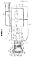
- Figure 1 is a partially cut way side view of a video camera to which a lens cap according to a first preferred embodiment of the invention is fitted;
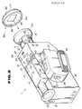
- Figure 2 is an enlarged perspective view of the video camera and lens cap shown in Figure 1;
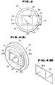
- Figure 3 is an enlarged front view of the lens cap, showing the lens cap mounting a title recording paper;
- Figure 4(A) and 4(B) are enlarged perspective views of the lens cap and the title recording paper, respectively;
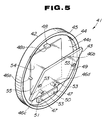
- Figure 5 is a perspective view of a lens cap according to a second preferred embodiment of the invention;
- Figure 6 is a rear view of the lens cap shown in Figure 5;
- Figure 7 is a cross-sectional view of the lens cap of Figures 5 and 6 taken along a line VII-VII in Figure 6;
- Figure 8 is an exploded perspective view of a lens cap according to a third preferred embodiment of the invention;
- Figure 9 is a rear view of the lens cap shown in Figure 8; and
- Figure 10 is a cross-sectional view of the lens cap of Figures 8 and 9 taken along a line X-X in Figure 9.
- The above-mentioned preferred embodiments of the invention will now be described.
- Figures 1 to 4(B) show a lens cap according to a first preferred embodiment of the invention, which lens cap is applicable to a video camera.
- As shown in Figures 1 and 2, a video camera 1 includes a frame or
casing 2. A rear part of a left side surface 3 (not shown in Figure 2) of thecamera frame 2 is formed with a cassette hole or opening 4 for removing a cassette from or inserting a cassette into theframe 2. Alid 5 is mounted for pivotal movement to open or close thecassette hole 4. A cassette holder (not shown), in which a tape cassette 6 is removably mounted, is provided in the inner surface of thelid 5. With the tape cassette 6 inserted in the cassette holder, thelid 5 is moved to the position in which thecassette hole 4 is closed, so that the tape cassette 6 is mounted in a recording and playback portion in theframe 2. - A
photographic lens 7 projects forwardly from afront surface 8 of theframe 2. Thelens 7 includes a lens mirror envelope 7a in which a plurality of fixed and movable lenses are installed. Azooming ring 9 and a focussingring 10 are rotatably fitted to the outside of the lens mirror envelope 7a for moving a predetermined one of the movable lenses in a predetermined range, in the direction of an optical axis, when rotated. An operation knob 11 and alock release button 12 are provided on thezooming ring 9. - When the
zooming ring 9 is rotated, a variator lens is moved so that a picture angle for an object being photographed by thephotographic lens 7 is changed. A focussing lens is moved and focussed together with rotation of the focussingring 10. When thelock release button 12 is pressed, thezooming ring 9 can be rotated further within a given range in the anticlockwise direction as viewed from the front surface of the video camera 1. When thezooming ring 9 is rotated within the above-described range (hereinafter also referred to as the macrofocus range), thephotographic lens 7 functions as a macrolens capable of photographing a close object, i.e. an object at a short distance away from the lens. Photographing of an object at a distance of up to about 6 millimetres can be carried out. - A
lens hood 13 is removably threaded on a front end portion of the focussingring 10. - The camera 1 further comprises a
microphone 14, an electronic view finder (EVF) 15 supported on a rear part of anupper surface 16 of theframe 2, aconnector 15a for connecting the EVF 15 to a circuit installed in theframe 2, a battery mounting portion 17 projecting from aright side surface 18 of theframe 2, and agrip belt 19. - A
mode selection button 20, for selecting different functional modes of the camera 1, is installed on theupper surface 16 of theframe 2. Thebutton 20 has a total of three positions, i.e. a first position in which the camera is put into a photography or camera mode, a second position in which the camera is put into a playback mode, and a third position which selects an off mode in which neither the camera mode nor the playback mode function is carried out - The camera has
operating buttons 21 operable in the playback mode of the camera, e.g. a playback button, a tape forward button, a tape rewind button, a stop button, and a pause button; andoperating buttons 22 operable during the photography of camera mode, e.g. an auto/manual switching button for white balance adjustment, an auto/manual switching button for focussing, a focussing button, and an inverse light correction button. - Further, the camera 1 has
operating buttons read button 23 for reading a title, acolour selection button 24 for selecting a colour for the title, and an on/off button 25 for storing a read title or for outputting a title stored in memory to an image recording circuit. - A
photography button 26 is disposed on a rear end portion of the battery mounting portion 17. The video camera 1 starts to perform photography when thephotography button 26 is pressed. - A
standby button 27 is movable between a non-standby position and a standby position. The non-standby position is immediately above thephotography button 26 and the standby position is more remotely above thephotography button 26. In the standby position, the video camera 1 can carry out photography or can read a title. - The camera 1 further comprises an electric-powered
zoom button 28 and acassette removal button 29. - When the
mode selection button 20 is moved to the photography (camera) mode selection position and thestandby button 27 is moved to the standby position, the video camera 1 is put in the photography (camera) mode, in which an image of an object captured by thelens 7 is displayed on a screen of theEVF 15. - When the
photography button 26 is depressed, an image captured by thelens 7 and audio (e.g. a voice) captured by themicrophone 14 are recorded by a record/playback portion (not shown) on a magnetic tape of the tape cassette 6. - Zooming during photography is carried out in response to operation of the electric-powered
zooming button 28 or in response to manual rotation of thezooming ring 9. Focussing is carried out automatically or manually. - Photographing a close object (an object at a short distance) is carried out with the
lock release button 12 depressed to enable the zoominglens 9 to rotate within the macrofocus range. - If the
lens hood 13 interferes with or disturbs the photographing of a close object (an object at a short distance), thelens hood 13 may be removed. - A title is stored as follows.
- With the
standby button 27 moved to the standby position and thephotographic lens 7 directed at a title recording paper, thephotograph lens 7 is focussed, the operator viewing the image displayed on theEVF 15. Theread button 23 is then depressed so that the image of the title element is converted into an electrical signal and temporarily stored in a memory in a record/playback circuit of the video camera 1. - Next, when the
colour selection button 24 is depressed, special abbreviated letters respectively representing a plurality of predetermined colours are displayed on the screen of theEVF 15. Whenever thebutton 24 is depressed, the display of the abbreviated letters is switched. When a representation of a desired colour is displayed, the on/offbutton 25 is depressed to select this colour. At this time, the signal indicative of the selected colour and the signal indicative of the title temporarily stored in the memory are stored in a memory and the image displayed on the screen of theEVF 15 disappears. The title thereby stored when the on/offbutton 25 is depressed is superposed on the image of the object to be photographed and recorded on the magnetic tape when thephotography button 26 is depressed to start photography. - A
lens cap 30 removably covers thephotographic lens 7 of the video camera 1 via thelens hood 13, chiefly for protecting thelens 7. - The
lens cap 30 includes amain part 31 which is disc-shaped and has a diameter slightly larger than that of a leading orfree end 13a of thelens hood 13, and afitting portion 32 which has circular ring shape and projects away from an outer peripheral edge of themain part 31 towards the video camera 1, as shown in Figure 2, theparts - A substantially
rectangular space 33 is formed within themain part 31 at a substantially central portion of themain part 31 as viewed in the direction of the thickness of themain part 31. In addition, windows (apertures) 34 and 35 are formed between aninner surface 31a (the surface nearer the video camera 1) of themain part 31 and thespace 33, and between anouter surface 31b of themain part 31 and thespace 33, respectively, thewindows space 33. - The
lens cap 30 further comprises light transmissive screens 36 and 37 formed of transparent or semitransparent synthetic resins, such as those of a milky white nature. Thescreens space 33, i.e. the dimension thereof in the direction of the thickness of themain part 31.Projections screen 37 facing thescreen 36. Thescreens space 33 with a gap between them being maintained by means of theprojections windows like screens - An introduction (entry) slit 39 is formed in the longitudinal direction between one end of the
title inserting portion 38 and the outer peripheral surface of themain part 31. Thelight transmissive screen 36 is transparent and thelight transmissive screen 37 is transparent or semitransparent. - The
lens cap 30 can serve to assist photographing of a title, in addition serving to protect thephotographic lens 7. That is to say, thelens cap 30, as shown in Figure 1, has itsfitting portion 32 fitted to the outside of theleading end portion 13a of thelens hood 13 of the video camera 1 so as to enclose thephotographic lens 7 via thelens hood 13. Thus, thelens 7 can be protected. In addition, a title recording paper can be attached to thelens hood 13, the paper being inserted in thetitle inserting portion 38. If this is done, the photographing of a title can be carried out extremely easily. - Referring to Figure 4(B), the
title recording paper 40 is made of a transparent or semitransparent paper or film of a synthetic resin. Therecording paper 40 has substantially the same width as that of thetitle inserting portion 38 and is substantially rectangular, having a length substantially equal to 1.5 times the length of thetitle inserting portion 38. As shown in Figure 4(B), aframe 40a having a size substantially the same as that of eachwindow paper 40 offset towards one end in the longitudinal direction. An arbitrary title element is marked (described) in theframe 40a. The arbitrary title element is marked by means of ink, relatively thick in colour, within theframe 40a of thepaper 40. Thepaper 40 is inserted into thetitle inserting portion 38 of thelens cap 30, through the introduction slit 39, as shown in Figure 3. At this time, with thelens cap 30 attached to thelens hood 13 and thestandby button 27 placed in the standby position, thephotographic lens 7 traps the title element marked on thetitle recording paper 40 and its image is displayed on the screen of theEVF 15. - Focussing of the lens on the object, i.e. the
title recording paper 40, is carried out by turning thezooming ring 9 within the adjustment range for macrophotography, i.e. the macrofocus range. - If the
read button 23 is then depressed, the title element marked (described) on thetitle recording paper 40 is temporarily stored in the memory. Therefore, when, as described above, upon completion of the colour selection operation effected by using thecolour selection button 24, the on/offswitch 25 is depressed, the title element is put into memory. - It should be noted that it is possible to mark the title element directly, by means of an aqueous pen, on the inner
light transmissive screen 36, without using thetitle recording paper 40. - Figures 5 to 7 show a
lens cap 41 according to a second preferred embodiment of the invention. - The
lens cap 41 includes a capmain body 42 formed of a semitransparent synthetic resin and apaper press 43 which is made of a transparent synthetic resin and is pivotally supported on the capmain body 42. - The cap
main body 42 includes amain part 44 which is disc-shaped and has a diameter slightly larger than the diameter of the leading orfree end 13a of thelens hood 13, and an integralfitting portion 45 which has a circular ring shape and which projects integrally from the outer peripheral edge portion of themain body 42 in the direction towards the video camera 1. - Four
positioning projections projections projection 48 extend from an inner surface 44a of themain part 44. Two (46a and 46b) of the fourpositioning projections main body part 44. The other two positioning projections (46c and 46d) are spaced apart from each other, towards the left and right, respectively, at a position near the bottom of themain body part 44. The two supportingprojections positioning projections engagement projection 48 is disposed at an upper central position on themain body part 44. The leading or free end of theengagement projection 48 is formed with anengagement portion 48a that projects towards the supportingprojections - The
paper press 43 includes apress plate 49 of a substantially square shape slightly smaller than a square inscribing the inner peripheral surface of thefitting portion 45 of the capmain body 42, and a projectingpiece 50 that projects downwardly from a central portion of the lower edge of thepress plate 49, theplate 49 and projectingpiece 50 being formed integrally. Athin hinge portion 51 is formed at a position adjacent thepress plate 49 and the projectingpiece 50. Mountingholes 52, 52 (only one of which is shown in Figure 7) are formed towards the left and right ends, respectively, of a lower edge of the projectingpiece 50. - The supporting
projections main body 42 are inserted through the mountingholes paper press 43 and parts of the projections are fixed to the inner surface 44a of themain part 44 of the capmain body 42 by means of a hot staking or cold staking operation. - Hence, the
paper press 43 is supported on the capmain body 42 in a state in which thepress plate 49 can be moved to make contact with or be separated from the inner surface 44a of themain part 44 of themain body 42, with thehinge portion 51 of thepaper press 43 acting as a pivoting fulcrum to enable the movement of the press plate. - It is to be noted that in the position of the
press plate 49 of thepaper press 43 in which thepress plate 49 overlaps with themain part 44 of the cap main body 42 (hereinafter referred to as the paper press position), thepositioning projections 46a to 46d are inserted intopositioning holes 53 so that thepress plate 49 can be located. The positioning holes 53 are formed at positions facing towards respective ones of thepositioning projections projections - When the
press plate 49 is disposed in the paper press position, its pivoting end edge is engaged with theengagement portion 48a of theengagement projection 48 of themain body 42. - The
lens cap 41 uses atitle recording paper 54 made of the same material as thetitle recording paper 40 used in the first preferred embodiment. Thetitle recording paper 54 is formed in a rectangular shape which is substantially smaller than thepress plate 49 of thepaper press 43. - To mount the
title recording paper 54 on thelens cap 41, thepress plate 49 of thepaper press 43 is pivoted so that thepress plate 49 is separated from themain part 44 of the capmain body 42 to some degree. Thetitle recording paper 54 is placed within aregion 55 enclosed within thepositioning projections 46a to 46d and theengagement projection 48. Thepaper press 49 is then moved to the paper press position. Thus, thetitle recording paper 54 is held sandwiched between themain part 44 of the capmain body 42 and thepress plate 49 of thepaper press 43. - If, with the
press plate 49 disposed in the paper press position and spaced apart from themain part 44, the tip or free end portion of theengagement projection 48 mounted on themain part 44 is forced to flex in the upward direction, the edge of the pivoting end of thepress plate 49 may be grasped by a fingertip and pulled towards the operator. - In the second preferred embodiment, an aqueous pen, etc., can be used to mark or describe a title element directly on the
region 55 of themain part 44, or at a position on thepress plate 49 corresponding to theregion 55, without using thetitle recording paper 54. - Figures 8 to 10 show a
lens cap 56 according to a third preferred embodiment of the invention. - The
lens cap 56 includes a capmain body 57, formed of a transparent or semitransparent synthetic resin, and apaper press 58 removably attached to the capmain body 57. - Parts of the cap
main body 57 andpaper press 58 having the same structure or the same function as parts of the capmain body 42 orpaper press 43 of thelens cap 41 of the second preferred embodiment are designated by the same references as those used in the second preferred embodiment and their descriptions will not be repeated. - Four
engagement projections 59 each of substantially hemispherical shape are formed symmetrically on the inner surface of thefitting portion 45 of the capmain body 57 with respect to the centre of themain part 44 of the capmain body 57. - The
paper press 58 is disc-shaped and is dimensioned so as to be capable of fitting tightly into thefitting portion 45 of the capmain body 57. When thepaper press 58 is fitted to the capmain body 57 so as to overlie the inner surface 44a of themain part 44 of the capmain body 57, theengagement projections 59 are engaged with the outer peripheral edge of thepaper press 58 whereby the paper press is grasped on the capmain body 57. - A
hole 60 is formed through an upper end of themain part 44. - When the
paper press 58 is attached to the capmain body 57 with thetitle recording paper 54 placed on aregion 61 enclosed within thepositioning projections main part 44 of the capmain body 57, thepaper 54 is held on thelens cap 56 with thepaper 54 being supported between the capmain body 57 andpaper press 58. - To remove the
title recording paper 54 from thelens cap 56, a fingertip of the operator is inserted from the front surface side into thehole 60 formed in the upper end of themain part 44 of the capmain body 57 to depress the upper end of thepaper press 58. Thepaper press 58 is thereby disengaged from theengagement projections 59 at its peripheral edge. Therefore, thepaper press 58 can be removed from the capmain body 57 and, subsequently, thetitle recording paper 54 can be removed from the capmain body 57. - It is to be noted that, in the third preferred embodiment, an aqueous pen can be used to describe or mark a title element directly on the
region 61 of themain part 44 of the capmain body 57, or on a position corresponding to theregion 61 of thepaper press 58. - The above-described lens caps are each removably attachable to a tip or free end portion of a photographic lens capable of photographing an object at a close distance and are provided with a region to which a title element can removably be attached. Therefore, the photographing of an arbitrary title can be carried out extremely easily.
- In addition, since the lens cap in which an arbitrary title element is provided on the above-mentioned region is attached to the photographic lens, title photographing can be carried out without hanging the title recording paper on a wall or without holding the title recording paper on a large-sized holding instrument. In addition, since the title photographing is carried out with a fixed positional relationship between the title element and the photographic lens, the title photographing operation is not adversely affected by the occurrence of camera vibrations.
- The lens cap embodying the invention enable the photographing of a title without using a special auxiliary instrument as described above, without selection of a special location for the photographing operation, and without being adversely affected by such vibrations as described above.
- In each preferred embodiment, the title arrangement region is provided by a structure in which the title recording paper is held between two plate-like light-transmissive members. However, the title arrangement region is not limited to those described in the respective preferred embodiments. That is to say, the title arrangement region of the lens cap can, in general, have an arbitrary structure in which an arbitrary title element can be removably installed. For example, the title region can be arranged such that a plurality of engagement portions enable engageable and disengageable insertion of a side edge portion and a side corner portion of the title recording paper in the region, these engagement portions suspending the title recording paper. Alternatively, at least part of the cap which faces the lens is transparent or semitransparent and is formed of a material to which a predetermined ink can be applied and can easily be wiped off (erased). In this case, a pen employing the predetermined ink can be used to mark or describe the title element directly on the related region.
- The invention is applicable to lens caps attachable to a photographic lens via a lens hood. However, the invention is also applicable to a lens cap removably attachable to a tip or end portion of photographic lens without the interposition of a lens hood. The invention is also applicable to lens caps for various types of camera photographic lenses.
Claims (16)
cap means (30; 41; 56) for removably covering a tip or end portion (13a) of a photographic lens (7) of the video camera (1), which lens is capable of photographing an object in a macro mode; and
holding means for supporting an object (40; 54; 49; 58), on which a title is or can be marked, on the cap means (30; 41; 56) so that the title can be photographed by the video camera (1) through the photographic lens (7).
providing a title marking within a light-transmissive lens cap (30; 41; 56);
fitting the lens cap (30; 41; 56) to the lens (7); and
operating the camera to photograph the title marking provided within the lens cap.
Applications Claiming Priority (2)
| Application Number | Priority Date | Filing Date | Title |
|---|---|---|---|
| JP62197210A JPS6440825A (en) | 1987-08-06 | 1987-08-06 | Lens cap |
| JP197210/87 | 1987-08-06 |
Publications (3)
| Publication Number | Publication Date |
|---|---|
| EP0302740A2 true EP0302740A2 (en) | 1989-02-08 |
| EP0302740A3 EP0302740A3 (en) | 1990-06-13 |
| EP0302740B1 EP0302740B1 (en) | 1995-05-10 |
Family
ID=16370656
Family Applications (1)
| Application Number | Title | Priority Date | Filing Date |
|---|---|---|---|
| EP88307249A Expired - Lifetime EP0302740B1 (en) | 1987-08-06 | 1988-08-05 | Lens caps |
Country Status (6)
| Country | Link |
|---|---|
| US (1) | US5162942A (en) |
| EP (1) | EP0302740B1 (en) |
| JP (1) | JPS6440825A (en) |
| KR (2) | KR890004200A (en) |
| AU (1) | AU622621B2 (en) |
| DE (1) | DE3853749T2 (en) |
Families Citing this family (13)
| Publication number | Priority date | Publication date | Assignee | Title |
|---|---|---|---|---|
| CN1122633A (en) * | 1993-05-10 | 1996-05-15 | Psc股份有限公司 | Bar code scanner with field replaceable window |
| US6204881B1 (en) | 1993-10-10 | 2001-03-20 | Canon Kabushiki Kaisha | Image data processing apparatus which can combine a plurality of images at different exposures into an image with a wider dynamic range |
| US5887009A (en) * | 1997-05-22 | 1999-03-23 | Optical Biopsy Technologies, Inc. | Confocal optical scanning system employing a fiber laser |
| US20070035699A1 (en) * | 2005-08-10 | 2007-02-15 | Mckee Joel V | Apparatus, system, and method for associating contemporaneous notes with photographed images using a camera slate |
| US20090002823A1 (en) * | 2007-06-30 | 2009-01-01 | David Law | Permanently-Affixed Lens Cap |
| US7717630B1 (en) | 2007-09-07 | 2010-05-18 | Kevin Wan | Lens cap with integral reference surface |
| US7843504B2 (en) * | 2007-09-27 | 2010-11-30 | Chung-Ho Jim Lee | Camera cap with a white balance insert |
| AT507236B1 (en) * | 2008-09-12 | 2010-06-15 | Swarovski Optik Kg | PROTECTIVE CAP |
| US8681267B2 (en) * | 2011-08-21 | 2014-03-25 | James Edward Sale | Lens cap with storage device |
| KR101256351B1 (en) * | 2011-11-22 | 2013-04-19 | 김석진 | Camera hood |
| US10900748B2 (en) | 2014-03-04 | 2021-01-26 | Sheltered Wings, Inc. | System and method for producing a DOPE chart |
| US10240897B2 (en) | 2014-03-04 | 2019-03-26 | Sheltered Wings, Inc. | Optic cover with releasably retained display |
| US9683812B2 (en) * | 2014-03-04 | 2017-06-20 | Sheltered Wings, Inc. | Optic cover with releasably retained display |
Citations (2)
| Publication number | Priority date | Publication date | Assignee | Title |
|---|---|---|---|---|
| US3682055A (en) * | 1969-01-31 | 1972-08-08 | Konan Camera Lab Co Ltd | Lens cap for camera |
| DE2208526A1 (en) * | 1972-02-23 | 1973-08-30 | Fritz Kamps | METHOD AND ADAPTER FOR MARKING FILMS |
Family Cites Families (14)
| Publication number | Priority date | Publication date | Assignee | Title |
|---|---|---|---|---|
| US2168594A (en) * | 1930-04-21 | 1939-08-08 | Anchor Cap & Closure Corp | Closure cap |
| US2583228A (en) * | 1946-07-08 | 1952-01-22 | Numbers William | Combined lens cover and lens brush |
| DE939192C (en) * | 1953-09-18 | 1956-02-16 | Zeiss Jena Veb Carl | Protective cover made of transparent material for lenses or eyepieces of optical devices, especially for camera lenses |
| US2961108A (en) * | 1957-12-19 | 1960-11-22 | Frances S Johnson | Magnifying cap for medicine bottle |
| US3133140A (en) * | 1960-09-23 | 1964-05-12 | Winchell Paul | Lens cover |
| DE7029487U (en) * | 1970-08-05 | 1971-02-11 | Licentia Gmbh | ARRANGEMENT TO PREVENT OBSERVATION DEVICES. |
| US3768688A (en) * | 1971-09-08 | 1973-10-30 | Gillette Co | Cap |
| US3796477A (en) * | 1972-09-25 | 1974-03-12 | Xomox Corp | Lens housing and lens cover for objective lens ring of an operating microscope |
| EP0083430A1 (en) * | 1981-12-14 | 1983-07-13 | Kenko Co., Ltd. | Filter holder for a photographic apparatus |
| FR2524152A1 (en) * | 1982-03-29 | 1983-09-30 | Alfille Jules | MODULAR ASSEMBLY FOR ALLOWING MISCELLANEOUS ACCESSORIES ON AN OPTICAL DEVICE LENS |
| JPS6096967A (en) * | 1983-11-01 | 1985-05-30 | Asahi Optical Co Ltd | Image pickup device of title for vtr camera |
| US4687312A (en) * | 1984-06-27 | 1987-08-18 | Panavision, Inc. | Matte box assembly |
| US4603785A (en) * | 1984-11-19 | 1986-08-05 | Sunbeam Plastics Corp. | Tamper indicating closure |
| JPS61257083A (en) * | 1985-05-10 | 1986-11-14 | Matsushita Electric Ind Co Ltd | Video camera device |
-
1987
- 1987-08-06 JP JP62197210A patent/JPS6440825A/en active Pending
-
1988
- 1988-07-22 US US07/223,418 patent/US5162942A/en not_active Expired - Fee Related
- 1988-07-26 AU AU20025/88A patent/AU622621B2/en not_active Ceased
- 1988-08-05 KR KR1019880009975A patent/KR890004200A/en not_active Application Discontinuation
- 1988-08-05 DE DE3853749T patent/DE3853749T2/en not_active Expired - Fee Related
- 1988-08-05 EP EP88307249A patent/EP0302740B1/en not_active Expired - Lifetime
-
1997
- 1997-07-31 KR KR2019970020591U patent/KR200159074Y1/en not_active IP Right Cessation
Patent Citations (2)
| Publication number | Priority date | Publication date | Assignee | Title |
|---|---|---|---|---|
| US3682055A (en) * | 1969-01-31 | 1972-08-08 | Konan Camera Lab Co Ltd | Lens cap for camera |
| DE2208526A1 (en) * | 1972-02-23 | 1973-08-30 | Fritz Kamps | METHOD AND ADAPTER FOR MARKING FILMS |
Non-Patent Citations (2)
| Title |
|---|
| PATENT ABSTRACTS OF JAPAN, vol. 11, no. 110 (E-496)[2557], 7th April 1987; & JP-A-61 257 083 (MATSUSHITA ELECTRIC IND. CO., LTD) 14-11-1986 * |
| PATENT ABSTRACTS OF JAPAN, vol. 9, no. 248 (E-347)[1971], 4th October 1985; & JP-A-60 096 967 (ASAHI KOUGAKU KOGYO K.K.) 30-05-1985 * |
Also Published As
| Publication number | Publication date |
|---|---|
| EP0302740A3 (en) | 1990-06-13 |
| US5162942A (en) | 1992-11-10 |
| KR890004200A (en) | 1989-04-20 |
| AU2002588A (en) | 1989-02-09 |
| AU622621B2 (en) | 1992-04-16 |
| KR200159074Y1 (en) | 1999-10-15 |
| DE3853749T2 (en) | 1995-10-12 |
| KR19990007077U (en) | 1999-02-25 |
| DE3853749D1 (en) | 1995-06-14 |
| EP0302740B1 (en) | 1995-05-10 |
| JPS6440825A (en) | 1989-02-13 |
Similar Documents
| Publication | Publication Date | Title |
|---|---|---|
| US7537399B2 (en) | Digital camera having camera body | |
| US6683653B1 (en) | Electronic camera and dial control device of electronic equipment | |
| EP0302740B1 (en) | Lens caps | |
| US5255120A (en) | Lens cap applicable to a video camera | |
| US6546207B2 (en) | Camera capable of inputting data and selectively displaying image | |
| US6515705B1 (en) | Electronic camera with an automatic lens cover | |
| JP4397058B2 (en) | Portable electronic devices | |
| JPH1065943A (en) | Video camera integrated recording and reproducing device | |
| JP3948003B2 (en) | Portable electronic devices | |
| KR960039860A (en) | Still camera integrated video camera | |
| JP4041930B2 (en) | Electronic camera | |
| US5784657A (en) | Camera having a display panel | |
| JP3807529B2 (en) | Electronic camera | |
| JP4449654B2 (en) | Electronic device dialing device | |
| JPH073735Y2 (en) | Camera with playback device | |
| JP2660065B2 (en) | camera | |
| JP3825880B2 (en) | Video camera | |
| JP2007006241A (en) | Digital camera | |
| JP3980467B2 (en) | binoculars | |
| JP3541970B2 (en) | Adapter for electronic camera | |
| JP2001042415A (en) | Photographic camera | |
| JPH07146507A (en) | Camera apparatus | |
| JPH08307748A (en) | Information recording and reproducing device | |
| JP2005157130A (en) | Lens cap | |
| JPS63261334A (en) | Video camera equipped with still camera |
Legal Events
| Date | Code | Title | Description |
|---|---|---|---|
| PUAI | Public reference made under article 153(3) epc to a published international application that has entered the european phase |
Free format text: ORIGINAL CODE: 0009012 |
|
| AK | Designated contracting states |
Kind code of ref document: A2 Designated state(s): DE FR GB NL |
|
| PUAL | Search report despatched |
Free format text: ORIGINAL CODE: 0009013 |
|
| AK | Designated contracting states |
Kind code of ref document: A3 Designated state(s): DE FR GB NL |
|
| 17P | Request for examination filed |
Effective date: 19901101 |
|
| 17Q | First examination report despatched |
Effective date: 19921113 |
|
| GRAA | (expected) grant |
Free format text: ORIGINAL CODE: 0009210 |
|
| AK | Designated contracting states |
Kind code of ref document: B1 Designated state(s): DE FR GB NL |
|
| REF | Corresponds to: |
Ref document number: 3853749 Country of ref document: DE Date of ref document: 19950614 |
|
| ET | Fr: translation filed | ||
| PLBE | No opposition filed within time limit |
Free format text: ORIGINAL CODE: 0009261 |
|
| STAA | Information on the status of an ep patent application or granted ep patent |
Free format text: STATUS: NO OPPOSITION FILED WITHIN TIME LIMIT |
|
| 26N | No opposition filed | ||
| PGFP | Annual fee paid to national office [announced via postgrant information from national office to epo] |
Ref country code: DE Payment date: 20010730 Year of fee payment: 14 |
|
| PGFP | Annual fee paid to national office [announced via postgrant information from national office to epo] |
Ref country code: GB Payment date: 20010801 Year of fee payment: 14 |
|
| PGFP | Annual fee paid to national office [announced via postgrant information from national office to epo] |
Ref country code: FR Payment date: 20010810 Year of fee payment: 14 |
|
| PGFP | Annual fee paid to national office [announced via postgrant information from national office to epo] |
Ref country code: NL Payment date: 20010830 Year of fee payment: 14 |
|
| REG | Reference to a national code |
Ref country code: GB Ref legal event code: IF02 |
|
| PG25 | Lapsed in a contracting state [announced via postgrant information from national office to epo] |
Ref country code: GB Free format text: LAPSE BECAUSE OF NON-PAYMENT OF DUE FEES Effective date: 20020805 |
|
| PG25 | Lapsed in a contracting state [announced via postgrant information from national office to epo] |
Ref country code: NL Free format text: LAPSE BECAUSE OF NON-PAYMENT OF DUE FEES Effective date: 20030301 Ref country code: DE Free format text: LAPSE BECAUSE OF NON-PAYMENT OF DUE FEES Effective date: 20030301 |
|
| GBPC | Gb: european patent ceased through non-payment of renewal fee |
Effective date: 20020805 |
|
| PG25 | Lapsed in a contracting state [announced via postgrant information from national office to epo] |
Ref country code: FR Free format text: LAPSE BECAUSE OF NON-PAYMENT OF DUE FEES Effective date: 20030430 |
|
| NLV4 | Nl: lapsed or anulled due to non-payment of the annual fee |
Effective date: 20030301 |
|
| REG | Reference to a national code |
Ref country code: FR Ref legal event code: ST |