EP0302850A2 - Artificial hip joint - Google Patents
Artificial hip joint Download PDFInfo
- Publication number
- EP0302850A2 EP0302850A2 EP88890181A EP88890181A EP0302850A2 EP 0302850 A2 EP0302850 A2 EP 0302850A2 EP 88890181 A EP88890181 A EP 88890181A EP 88890181 A EP88890181 A EP 88890181A EP 0302850 A2 EP0302850 A2 EP 0302850A2
- Authority
- EP
- European Patent Office
- Prior art keywords
- joint
- head
- meridian section
- axis
- socket
- Prior art date
- Legal status (The legal status is an assumption and is not a legal conclusion. Google has not performed a legal analysis and makes no representation as to the accuracy of the status listed.)
- Granted
Links
Images
Classifications
-
- A—HUMAN NECESSITIES
- A61—MEDICAL OR VETERINARY SCIENCE; HYGIENE
- A61F—FILTERS IMPLANTABLE INTO BLOOD VESSELS; PROSTHESES; DEVICES PROVIDING PATENCY TO, OR PREVENTING COLLAPSING OF, TUBULAR STRUCTURES OF THE BODY, e.g. STENTS; ORTHOPAEDIC, NURSING OR CONTRACEPTIVE DEVICES; FOMENTATION; TREATMENT OR PROTECTION OF EYES OR EARS; BANDAGES, DRESSINGS OR ABSORBENT PADS; FIRST-AID KITS
- A61F2/00—Filters implantable into blood vessels; Prostheses, i.e. artificial substitutes or replacements for parts of the body; Appliances for connecting them with the body; Devices providing patency to, or preventing collapsing of, tubular structures of the body, e.g. stents
- A61F2/02—Prostheses implantable into the body
- A61F2/30—Joints
- A61F2/32—Joints for the hip
- A61F2/36—Femoral heads ; Femoral endoprostheses
- A61F2/3609—Femoral heads or necks; Connections of endoprosthetic heads or necks to endoprosthetic femoral shafts
-
- A—HUMAN NECESSITIES
- A61—MEDICAL OR VETERINARY SCIENCE; HYGIENE
- A61F—FILTERS IMPLANTABLE INTO BLOOD VESSELS; PROSTHESES; DEVICES PROVIDING PATENCY TO, OR PREVENTING COLLAPSING OF, TUBULAR STRUCTURES OF THE BODY, e.g. STENTS; ORTHOPAEDIC, NURSING OR CONTRACEPTIVE DEVICES; FOMENTATION; TREATMENT OR PROTECTION OF EYES OR EARS; BANDAGES, DRESSINGS OR ABSORBENT PADS; FIRST-AID KITS
- A61F2/00—Filters implantable into blood vessels; Prostheses, i.e. artificial substitutes or replacements for parts of the body; Appliances for connecting them with the body; Devices providing patency to, or preventing collapsing of, tubular structures of the body, e.g. stents
- A61F2/02—Prostheses implantable into the body
- A61F2/30—Joints
- A61F2002/30001—Additional features of subject-matter classified in A61F2/28, A61F2/30 and subgroups thereof
- A61F2002/30621—Features concerning the anatomical functioning or articulation of the prosthetic joint
- A61F2002/30649—Ball-and-socket joints
- A61F2002/30654—Details of the concave socket
- A61F2002/30655—Non-spherical concave inner surface
- A61F2002/30657—Non-spherical concave inner surface made of different partially-spherical concave portions
- A61F2002/30658—Non-spherical concave inner surface made of different partially-spherical concave portions having a central conforming area surrounded by a peripheral annular non-conforming area
-
- A—HUMAN NECESSITIES
- A61—MEDICAL OR VETERINARY SCIENCE; HYGIENE
- A61F—FILTERS IMPLANTABLE INTO BLOOD VESSELS; PROSTHESES; DEVICES PROVIDING PATENCY TO, OR PREVENTING COLLAPSING OF, TUBULAR STRUCTURES OF THE BODY, e.g. STENTS; ORTHOPAEDIC, NURSING OR CONTRACEPTIVE DEVICES; FOMENTATION; TREATMENT OR PROTECTION OF EYES OR EARS; BANDAGES, DRESSINGS OR ABSORBENT PADS; FIRST-AID KITS
- A61F2/00—Filters implantable into blood vessels; Prostheses, i.e. artificial substitutes or replacements for parts of the body; Appliances for connecting them with the body; Devices providing patency to, or preventing collapsing of, tubular structures of the body, e.g. stents
- A61F2/02—Prostheses implantable into the body
- A61F2/30—Joints
- A61F2/30767—Special external or bone-contacting surface, e.g. coating for improving bone ingrowth
- A61F2/30771—Special external or bone-contacting surface, e.g. coating for improving bone ingrowth applied in original prostheses, e.g. holes or grooves
- A61F2002/3082—Grooves
-
- A—HUMAN NECESSITIES
- A61—MEDICAL OR VETERINARY SCIENCE; HYGIENE
- A61F—FILTERS IMPLANTABLE INTO BLOOD VESSELS; PROSTHESES; DEVICES PROVIDING PATENCY TO, OR PREVENTING COLLAPSING OF, TUBULAR STRUCTURES OF THE BODY, e.g. STENTS; ORTHOPAEDIC, NURSING OR CONTRACEPTIVE DEVICES; FOMENTATION; TREATMENT OR PROTECTION OF EYES OR EARS; BANDAGES, DRESSINGS OR ABSORBENT PADS; FIRST-AID KITS
- A61F2/00—Filters implantable into blood vessels; Prostheses, i.e. artificial substitutes or replacements for parts of the body; Appliances for connecting them with the body; Devices providing patency to, or preventing collapsing of, tubular structures of the body, e.g. stents
- A61F2/02—Prostheses implantable into the body
- A61F2/30—Joints
- A61F2/30767—Special external or bone-contacting surface, e.g. coating for improving bone ingrowth
- A61F2002/30934—Special articulating surfaces
-
- A—HUMAN NECESSITIES
- A61—MEDICAL OR VETERINARY SCIENCE; HYGIENE
- A61F—FILTERS IMPLANTABLE INTO BLOOD VESSELS; PROSTHESES; DEVICES PROVIDING PATENCY TO, OR PREVENTING COLLAPSING OF, TUBULAR STRUCTURES OF THE BODY, e.g. STENTS; ORTHOPAEDIC, NURSING OR CONTRACEPTIVE DEVICES; FOMENTATION; TREATMENT OR PROTECTION OF EYES OR EARS; BANDAGES, DRESSINGS OR ABSORBENT PADS; FIRST-AID KITS
- A61F2/00—Filters implantable into blood vessels; Prostheses, i.e. artificial substitutes or replacements for parts of the body; Appliances for connecting them with the body; Devices providing patency to, or preventing collapsing of, tubular structures of the body, e.g. stents
- A61F2/02—Prostheses implantable into the body
- A61F2/30—Joints
- A61F2/32—Joints for the hip
- A61F2002/3225—Joints for the hip the diameter of the inner concave femoral head-receiving cavity of the inner acetabular shell being essentially greater than the diameter of the convex femoral head
-
- A—HUMAN NECESSITIES
- A61—MEDICAL OR VETERINARY SCIENCE; HYGIENE
- A61F—FILTERS IMPLANTABLE INTO BLOOD VESSELS; PROSTHESES; DEVICES PROVIDING PATENCY TO, OR PREVENTING COLLAPSING OF, TUBULAR STRUCTURES OF THE BODY, e.g. STENTS; ORTHOPAEDIC, NURSING OR CONTRACEPTIVE DEVICES; FOMENTATION; TREATMENT OR PROTECTION OF EYES OR EARS; BANDAGES, DRESSINGS OR ABSORBENT PADS; FIRST-AID KITS
- A61F2/00—Filters implantable into blood vessels; Prostheses, i.e. artificial substitutes or replacements for parts of the body; Appliances for connecting them with the body; Devices providing patency to, or preventing collapsing of, tubular structures of the body, e.g. stents
- A61F2/02—Prostheses implantable into the body
- A61F2/30—Joints
- A61F2/32—Joints for the hip
- A61F2002/3233—Joints for the hip having anti-luxation means for preventing complete dislocation of the femoral head from the acetabular cup
-
- A—HUMAN NECESSITIES
- A61—MEDICAL OR VETERINARY SCIENCE; HYGIENE
- A61F—FILTERS IMPLANTABLE INTO BLOOD VESSELS; PROSTHESES; DEVICES PROVIDING PATENCY TO, OR PREVENTING COLLAPSING OF, TUBULAR STRUCTURES OF THE BODY, e.g. STENTS; ORTHOPAEDIC, NURSING OR CONTRACEPTIVE DEVICES; FOMENTATION; TREATMENT OR PROTECTION OF EYES OR EARS; BANDAGES, DRESSINGS OR ABSORBENT PADS; FIRST-AID KITS
- A61F2/00—Filters implantable into blood vessels; Prostheses, i.e. artificial substitutes or replacements for parts of the body; Appliances for connecting them with the body; Devices providing patency to, or preventing collapsing of, tubular structures of the body, e.g. stents
- A61F2/02—Prostheses implantable into the body
- A61F2/30—Joints
- A61F2/32—Joints for the hip
- A61F2/34—Acetabular cups
- A61F2002/344—Acetabular cups the inner shell having an inner hip femoral head-receiving cavity offset from its centre line
-
- A—HUMAN NECESSITIES
- A61—MEDICAL OR VETERINARY SCIENCE; HYGIENE
- A61F—FILTERS IMPLANTABLE INTO BLOOD VESSELS; PROSTHESES; DEVICES PROVIDING PATENCY TO, OR PREVENTING COLLAPSING OF, TUBULAR STRUCTURES OF THE BODY, e.g. STENTS; ORTHOPAEDIC, NURSING OR CONTRACEPTIVE DEVICES; FOMENTATION; TREATMENT OR PROTECTION OF EYES OR EARS; BANDAGES, DRESSINGS OR ABSORBENT PADS; FIRST-AID KITS
- A61F2/00—Filters implantable into blood vessels; Prostheses, i.e. artificial substitutes or replacements for parts of the body; Appliances for connecting them with the body; Devices providing patency to, or preventing collapsing of, tubular structures of the body, e.g. stents
- A61F2/02—Prostheses implantable into the body
- A61F2/30—Joints
- A61F2/32—Joints for the hip
- A61F2/34—Acetabular cups
- A61F2002/3453—Acetabular cups having a non-hemispherical convex outer surface, e.g. quadric-shaped
-
- A—HUMAN NECESSITIES
- A61—MEDICAL OR VETERINARY SCIENCE; HYGIENE
- A61F—FILTERS IMPLANTABLE INTO BLOOD VESSELS; PROSTHESES; DEVICES PROVIDING PATENCY TO, OR PREVENTING COLLAPSING OF, TUBULAR STRUCTURES OF THE BODY, e.g. STENTS; ORTHOPAEDIC, NURSING OR CONTRACEPTIVE DEVICES; FOMENTATION; TREATMENT OR PROTECTION OF EYES OR EARS; BANDAGES, DRESSINGS OR ABSORBENT PADS; FIRST-AID KITS
- A61F2/00—Filters implantable into blood vessels; Prostheses, i.e. artificial substitutes or replacements for parts of the body; Appliances for connecting them with the body; Devices providing patency to, or preventing collapsing of, tubular structures of the body, e.g. stents
- A61F2/02—Prostheses implantable into the body
- A61F2/30—Joints
- A61F2/32—Joints for the hip
- A61F2/34—Acetabular cups
- A61F2002/348—Additional features
- A61F2002/3493—Spherical shell significantly greater than a hemisphere, e.g. extending over more than 200 degrees
-
- A—HUMAN NECESSITIES
- A61—MEDICAL OR VETERINARY SCIENCE; HYGIENE
- A61F—FILTERS IMPLANTABLE INTO BLOOD VESSELS; PROSTHESES; DEVICES PROVIDING PATENCY TO, OR PREVENTING COLLAPSING OF, TUBULAR STRUCTURES OF THE BODY, e.g. STENTS; ORTHOPAEDIC, NURSING OR CONTRACEPTIVE DEVICES; FOMENTATION; TREATMENT OR PROTECTION OF EYES OR EARS; BANDAGES, DRESSINGS OR ABSORBENT PADS; FIRST-AID KITS
- A61F2/00—Filters implantable into blood vessels; Prostheses, i.e. artificial substitutes or replacements for parts of the body; Appliances for connecting them with the body; Devices providing patency to, or preventing collapsing of, tubular structures of the body, e.g. stents
- A61F2/02—Prostheses implantable into the body
- A61F2/30—Joints
- A61F2/32—Joints for the hip
- A61F2/36—Femoral heads ; Femoral endoprostheses
- A61F2/3609—Femoral heads or necks; Connections of endoprosthetic heads or necks to endoprosthetic femoral shafts
- A61F2002/3611—Heads or epiphyseal parts of femur
- A61F2002/3623—Non-spherical heads
Landscapes
- Health & Medical Sciences (AREA)
- Orthopedic Medicine & Surgery (AREA)
- Cardiology (AREA)
- Oral & Maxillofacial Surgery (AREA)
- Transplantation (AREA)
- Engineering & Computer Science (AREA)
- Biomedical Technology (AREA)
- Heart & Thoracic Surgery (AREA)
- Vascular Medicine (AREA)
- Life Sciences & Earth Sciences (AREA)
- Animal Behavior & Ethology (AREA)
- General Health & Medical Sciences (AREA)
- Public Health (AREA)
- Veterinary Medicine (AREA)
- Prostheses (AREA)
Abstract
Description
Die Erfindung betrifft ein künstliches Hüftgelenk zum Ersatz des natürlichen Gelenkskopfes und/oder der natürlichen Gelenkspfanne, wobei die künstlichen Gelenksflächen als Rotationsflächen ausgebildet sind.The invention relates to an artificial hip joint to replace the natural joint head and / or the natural joint socket, the artificial joint surfaces being designed as surfaces of revolution.
Es ist bekannt, künstliche Hüftgelenke mit im wesentlichen als Kugelflächen ausgebildeten Gelenksflächen sowohl in der Gelenkspfanne als auch im Gelenkskopf herzustellen. Obwohl derartige Hüftgelenke einen guten Ersatz für krankhaft veränderte bzw. von Geburt auf schlechte Hüftgelenke geboten haben,kam es immer wieder nach Implantationen künstlicher Hüftgelenke zu Gehschwierigkeiten und Behinderungen der Patienten.It is known to produce artificial hip joints with joint surfaces essentially designed as spherical surfaces both in the joint socket and in the joint head. Although such hip joints have been a good substitute for pathologically changed hip joints or those that were bad from birth, there were always walking difficulties and handicaps after the implantation of artificial hip joints.
Der Erfindung liegt die Aufgabe zugrunde, hier Abhilfe oder zumindest eine Besserung des herrschenden Zustandes auf dem Gebiet der künstlichen Hüftgelenke zu schaffen. Erreicht wird dies, wenn gemäß der Erfindung die Gelenksfläche der Gelenkspfanne bzw. die Gelenksfläche des Gelenkskopfes im Meridianschnitt als Pascal'sche Kurve (Schnecke) ausgebildet ist. Durch diese Ausgestaltung wird erreicht, daß bei jeder Abweichung zwischen den Drehachsen von Gelenkspfanne und Gelenkskopf ein Rückstellmoment auftritt, so daß jede indifferente Gleichgewichtslage, wenn man von einer einzigen Stellung absieht, in der die Achsen von Gelenkspfanne und Gelenkskopf fluchten, vermieden ist. Der mit einem künstlichen Hüftgelenk versorgte Patient kann sohin das Gelenk der neuen Ausgestaltung besser bewegen als wenn - wie bisher - jede Lage praktisch eine indifferente Gleichgewichtslage ist.The object of the invention is to remedy or at least improve the prevailing condition in the field of artificial hip joints. This is achieved if, according to the invention, the joint surface of the joint socket or the joint surface of the joint head is designed as a Pascal curve (worm) in the meridian section. This configuration ensures that a restoring torque occurs with every deviation between the axes of rotation of the joint socket and the joint head, so that any indifferent equilibrium position, if one does not count from a single position in which the axes of the joint socket and the joint head are aligned, is avoided. The patient, who is provided with an artificial hip joint, can move the joint of the new design better than if - as before - each position is practically an indifferent equilibrium position.
Bevorzugt ist es, den Meridianschnitt der Gelenksfläche der Gelenkspfanne als gestreckte Pascal'sche Kurve auszubilden. Der Meridianschnitt der Gelenksfläche des Kopfes ist dann bevorzugt eine Pascal'sche Kurve mit Schlinge.It is preferred to design the meridian section of the joint surface of the joint socket as an elongated Pascal curve. The meridian section of the articular surface of the head is then preferably a Pascal curve with a loop.
Eine weitere Ausgestaltung des erfindungsgemäßen Hüftgelenkes zeichnet sich dadurch aus, daß der Meridianschnitt der Gelenksfläche der Gelenkspfanne und der Meridianschnitt der Gelenksfläche des Gelenkskopfes Pascalkurven mit gegeneinander vertauschten Parametern sind, d.h. folgt der Meridianschnitt des Hüftkopfes der Beziehung r = a + b cos φ , so folgt der Meridianschnitt der Hüftpfanne der Beziehung r′ = b + a cos φ , wobei r bzw. r′ und φ die Polarkoordinaten eines Punktes des Meridianschnittes des Hüftkopfes bzw. der Hüftpfanne sind und φ den Winkel zwischen der Symmetrieachse der Pascal'schen Kurve und den Radiusvektor in einem Punkt der Kurve bedeutet und a und b die vorgegebenen Parameter sind.Another embodiment of the invention Hip joint is characterized in that the meridian section of the joint surface of the joint socket and the meridian section of the joint surface of the joint head are Pascal curves with interchanged parameters, i.e. if the meridian section of the femoral head follows the relationship r = a + b cos φ, the meridian section of the hip socket follows Relationship r ′ = b + a cos φ, where r or r ′ and φ are the polar coordinates of a point of the meridian section of the femoral head or acetabulum and φ is the angle between the symmetry axis of Pascal's curve and the radius vector at a point of Curve means and a and b are the given parameters.
Das Verhältnis der beiden Parameter ![]()
![]()
Eine weitere Erfindung sieht vor, daß zwischen der Achse des Schenkelhalses und der Drehachse des Gelenkskopfes (gesehen in Draufsicht) eine winkelmäßige Abweichung vorhanden ist, die bevorzugt 10,7° +/- 3° beträgt. Durch dieses Ausgestaltung wird erreicht, daß Totlagen zwischen Becken und Oberschenkel vermieden sind und auf den Oberschenkel immer ein Rückstellmoment wirkt. Durch die erfindungsgemäße Ausgestaltung des künstlichen Hüftgelenkes wird erreicht, daß die Drehachse des Gelenkskopfes durch die Oberschenkelknochenschaftachse verläuft, die Schenkelhalsachse jedoch bauchseitig (ventral) an der Oberschenkelschaftachse vorbeiläuft. Wiewohl diese erfindungsgemäße Gestaltung besonders zweckmäßig bei künstlichen Hüftgelenken angewendet wird, bei denen die Gelenksfläche der Gelenkspfanne bzw. die Gelenksfläche des Gelenkskopfes im Meridianschnitt als Pascal'sche Kurve (Schnecke), insbes.solchen mit den vorerwähnten Merkmalen ausgebildet ist, kann sie auch mit dem Vorteil der Vermeidung von Totlagen zwischen Becken und Oberschenkel bei künstlichen Hüftgelenken angewendet werden, bei welchen Gelenkskopf und/oder Gelenkspfanne in herkömmlicher Weise (kugelförmig) gestaltet sind.Another invention provides that there is an angular deviation between the axis of the femoral neck and the axis of rotation of the joint head (seen in plan view), which is preferably 10.7 ° +/- 3 °. This configuration ensures that dead positions between the pelvis and thigh are avoided and a restoring moment always acts on the thigh. The inventive design of the artificial hip joint ensures that the axis of rotation of the joint head runs through the axis of the femur shaft, but the axis of the femoral neck runs past the axis of the thigh shaft (ventrally). Although this design according to the invention is particularly expediently used in artificial hip joints in which the joint surface of the joint socket or the joint surface of the joint head in the meridian section is designed as a Pascal curve (snail), in particular with the aforementioned characteristics, it can also be designed with the The advantage of avoiding dead positions between the pelvis and thigh can be used in artificial hip joints in which the joint head and / or joint socket are designed in a conventional manner (spherical).
Die Erfindung wird nachstehend anhand der Zeichnung beispielsweise näher erläutert. Es zeigen,
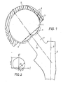
- Fig. 1 einen Achsschnitt durch ein aus Gelenkskopf und Gelenkspfanne bestehendes, erfindungsgemäß ausgebildetes Hüftgelenk,
- Fig. 2 ein Schaubild zur Erläuterung des mathematischen Zusammenhanges, und
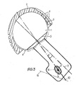
- Fig. 3 eine Draufsicht korrespondierend zu Fig. 1 mit geschnittener Gelenkspfanne.
- 1 shows an axial section through an inventive hip joint consisting of a joint head and an acetabular cup,
- Fig. 2 is a graph for explaining the mathematical relationship, and
- Fig. 3 is a plan view corresponding to Fig. 1 with a cut joint socket.
In der Zeichnung ist mit 1 der Gelenkskopf und mit 2 die Pfanne bezeichnet. Gelenkskopf 1 und Gelenkspfanne 2 sind als Drehkörper bzw. Drehflächen ausgebildet, wobei sowohl die Gelenksfläche 3 der Gelenkspfanne 2 als auch die Gelenksfläche 4 des Gelenkskopfes 1 einen von einer Pascalkurve (Pascalschnecke) gebildeten Meridianschnitt besitzen. Der Meridianschnitt der Gelenksfläche 4 des Gelenkskopfes 1 ist dabei als Pascal'sche Kurve mit Schlinge ausgebildet, wie aus Fig. 1 zu ersehen ist. Selbstverständlich wird dabei nur jener Teil der Pascal'schen Kurve verwendet, der oberhalb des Kehlkreises 5 angeordnet ist, d.i. ein Kreis, der senkrecht zur Drehachse liegt und durch den Doppelpunkt der Pascal'schen Kurve verläuft. Der Meridianschnitt der Gelenksfläche 3 der Gelenkspfanne 2 ist eine gestreckte Pascal'sche Kurve, d.h. eine Kurve, die eine auf der Symmetrieachse liegende Eindellung besitzt. Der Meridianschnitt der Gelenksfläche 3 der Gelenkspfanne 2 und der Meridianschnitt der Gelenksfläche 4 des Gelenkskopfes 1 sind Pascalkurven mit gegeneinander vertauschten Parametern.In the drawing, 1 denotes the joint head and 2 the socket. The joint head 1 and the
In Fig. 2 ist zur näheren Veranschaulichung eine Pascalschnecke mit Schlinge dargestellt. In Polarkoordinaten folgen die Punkte dieser Pascal'schen Kurve der Gleichung r = a + b cos φ .A Pascal snail with a loop is shown in FIG. 2 for a more detailed illustration. The points of this Pascal curve follow the equation r = a + b cos φ in polar coordinates.
Legt man durch die Pascal'sche Kurve ein ζ/η Koordinatensystem derart, daß die η -Achse mit der Symmetrieachse der Pascal'schen Kurve zusammenfällt und der Ursprung des Koordinatensystems mit dem Doppelpunkt der Pascal'schen Kurve zusammenfällt, so sind die Parameter a bzw. a + b als Achsenabschnitte der Pascal'schen Kurve festgelegt, wobei der Winkel φ als Winkel des jeweiligen Radiusvektors r gegen die Symmetrieachse (η-Achse) gemessen ist.If you put a ζ / η coordinate system through the Pascal curve such that the η axis coincides with the symmetry axis of the Pascal curve and the origin of the coordinate system with the colon of the Pascal's curve coincides, the parameters a and a + b are defined as intercepts of the Pascal's curve, the angle φ being measured as the angle of the respective radius vector r against the axis of symmetry (η axis).
Folgt nun der Meridianschnitt der Hüftpfanne 2 der Beziehung r′ = b + a cos.φ , so folgt der Meridianschnitt des Hüftkopfes der Beziehung r = a + b cos.φ. Es ergibt sich dabei, daß sowohl der Meridianschnitt der HÜftpfanne 2 als auch der Meridianschnitt des Hüftkopfes 1 auf der Symmetrieachse die gleiche Abschnittgröße, nämlich a + b, besitzen. Auf der dazu senkrechten Achse besitzt der Meridianschnitt des Hüftkopfes 1 den Achsenabschnitt a, der Meridianschnitt der Hüftpfanne 2 jedoch den Achsenabschnitt b. Die Wahl ist so getroffen, daß b> a. Bevorzugte Werte sind hiebei für a 18,75 mm und für b 21,5 mm.If the meridian section of the
Im dargestellten Ausführungsbeispiel besteht die Gelenkspfanne 2 aus Kunststoff. Am Außenmantel sind dabei in Umfangsrichtung senkrecht zur Drehachse mehrere Nuten 6 zwecks Verankerung der Gelenkspfanne im Becken mittels eines entsprechenden Zementes (Kunststoffkleber) angeordnet. Der Gelenkskopf 1 ist im dargestellten Ausführungsbeispiel als ein Stück mit Hals 7 und dem Schaft 8, der in den Oberschenkelknochen (Femur) implantiert wird, dargestellt. Es ist jedoch auch möglich, den Gelenkskopf 1 auf einen Zapfen, dessen Achse mit der Drehachse des Gelenkskopfes 1 zusammenfällt und aus einem Stück mit dem Schaft 7 besteht, aufzustecken. In einem solchen Fall kann dann der Gelenkskopf 1 auch aus Kunststoff bestehen.In the illustrated embodiment, the
Wie aus Fig. 3 ersichtlich, ist zwischen der Achse 11 des Schwenkhalses und der Drehachse 10 des Gelenkskopfes 1, die mit der Achse 9 des Schaftes 8 des Oberschenkels bzw. der Prothese in einer Ebene liegt, eine winkelmäßige Abweichung vorhanden. Diese Abweichung beträgt bevorzugt 10,7° +/- 3°. Der Markraum 12 des Oberschenkelknochens, in welchen der Schaft 8 eingesetzt wird, ist strichpunktiert in Fig. 3 dargestellt. Die Drehachse 10 des Gelenkskopfes schließt mit der Achse 9 des Schaftes 8 einen Winkel von etwa 126° ein. In Draufsicht (Fig. 3) schließt die Drehachse 10 des Gelenkskopfes 1 mit der hinteren Femurcondylenachse 14 einen Winkel von etwa 34° ein. Die aus den Zeichnungen ersichtlichen Winkellagen der Achsen 10 und 11 (Fig. 3) bzw. 9 und 10 (Fig. 1)können auch bei künstlichen Hüftgelenken angewendet werden, deren Gelenkskopf bzw. Gelenkspfanne in herkömmlicher Weise (z.B. kugelförmig) ausgebildet sind.3, there is an angular deviation between the axis 11 of the swivel neck and the axis of
Claims (6)
Applications Claiming Priority (2)
| Application Number | Priority Date | Filing Date | Title |
|---|---|---|---|
| AT1738/87 | 1987-07-09 | ||
| AT0173887A AT386948B (en) | 1987-07-09 | 1987-07-09 | ARTIFICIAL HIP JOINT |
Publications (3)
| Publication Number | Publication Date |
|---|---|
| EP0302850A2 true EP0302850A2 (en) | 1989-02-08 |
| EP0302850A3 EP0302850A3 (en) | 1989-11-08 |
| EP0302850B1 EP0302850B1 (en) | 1993-01-13 |
Family
ID=3519935
Family Applications (1)
| Application Number | Title | Priority Date | Filing Date |
|---|---|---|---|
| EP88890181A Expired - Lifetime EP0302850B1 (en) | 1987-07-09 | 1988-07-07 | Artificial hip joint |
Country Status (6)
| Country | Link |
|---|---|
| US (1) | US4911723A (en) |
| EP (1) | EP0302850B1 (en) |
| JP (1) | JPS6470040A (en) |
| AT (2) | AT386948B (en) |
| CA (1) | CA1296837C (en) |
| DE (1) | DE3877457D1 (en) |
Cited By (12)
| Publication number | Priority date | Publication date | Assignee | Title |
|---|---|---|---|---|
| WO1995023566A1 (en) * | 1994-03-03 | 1995-09-08 | University Of Leeds | Acetabular cup |
| WO1996004867A1 (en) * | 1994-08-10 | 1996-02-22 | Theusner, Joachim | Artificial joint, in particular artificial human hip joint |
| EP0716838A3 (en) * | 1994-11-28 | 1996-06-26 | Biomedical Eng Trust Inc | |
| WO1997016137A1 (en) * | 1995-10-31 | 1997-05-09 | Sarkisian James S | Prosthetic joint and method of manufacture |
| WO1997016138A1 (en) * | 1995-11-02 | 1997-05-09 | Wright Medical Technology, Inc. | Low-wear ball and cup joint prosthesis |
| WO2002043626A1 (en) * | 2000-12-01 | 2002-06-06 | Depuy International Limited | An orthopaedic joint prosthesis |
| US6610097B2 (en) | 2000-03-15 | 2003-08-26 | Depuy Orthopaedics, Inc. | Prosthetic cup assembly which includes components possessing self-locking taper and associated method |
| US7879106B2 (en) | 2002-03-26 | 2011-02-01 | Smith & Nephew, Inc. | Hip joint prosthesis |
| US8123815B2 (en) | 2008-11-24 | 2012-02-28 | Biomet Manufacturing Corp. | Multiple bearing acetabular prosthesis |
| US8308810B2 (en) | 2009-07-14 | 2012-11-13 | Biomet Manufacturing Corp. | Multiple bearing acetabular prosthesis |
| US8652213B2 (en) | 2007-12-28 | 2014-02-18 | DePuy Synthes Products, LLC | Aspheric hip bearing couple |
| US8715364B2 (en) | 2007-02-05 | 2014-05-06 | DePuy Synthes Products, LLC | Aspheric hip bearing couple |
Families Citing this family (21)
| Publication number | Priority date | Publication date | Assignee | Title |
|---|---|---|---|---|
| DE4232313C1 (en) * | 1992-09-26 | 1994-04-28 | Kubein Meesenburg Dietmar | Artificial joint as an endoprosthesis for the human shoulder joint |
| US5928285A (en) * | 1997-05-30 | 1999-07-27 | Bristol-Myers Squibb Co. | Orthopaedic implant having an articulating surface with a conforming and translational surface |
| AU755807B2 (en) * | 1998-11-05 | 2002-12-19 | Louis U. Bigliani | Orthopaedic implant having an articulating surface with a conforming and translational surface |
| US7497874B1 (en) | 2001-02-23 | 2009-03-03 | Biomet Manufacturing Corp. | Knee joint prosthesis |
| US20020120340A1 (en) | 2001-02-23 | 2002-08-29 | Metzger Robert G. | Knee joint prosthesis |
| US7326253B2 (en) | 2001-11-16 | 2008-02-05 | Depuy Products, Inc. | Prosthetic cup assembly having increased assembly congruency |
| US20050261776A1 (en) * | 2004-05-19 | 2005-11-24 | Howmedica Osteonics Corp. | Prosthetic joint with annular contact bearing surface |
| GB0519490D0 (en) * | 2005-09-23 | 2005-11-02 | Benoist Girard Sas | Prosthetic joints |
| WO2007108848A1 (en) | 2006-03-20 | 2007-09-27 | Smith & Nephew, Inc. | Acetabular cup assembly for multiple bearing materials |
| JP5448842B2 (en) | 2007-01-10 | 2014-03-19 | バイオメト マニファクチャリング コーポレイション | Knee joint prosthesis system and implantation method |
| US8187280B2 (en) | 2007-10-10 | 2012-05-29 | Biomet Manufacturing Corp. | Knee joint prosthesis system and method for implantation |
| US8163028B2 (en) | 2007-01-10 | 2012-04-24 | Biomet Manufacturing Corp. | Knee joint prosthesis system and method for implantation |
| US8562616B2 (en) | 2007-10-10 | 2013-10-22 | Biomet Manufacturing, Llc | Knee joint prosthesis system and method for implantation |
| US8328873B2 (en) | 2007-01-10 | 2012-12-11 | Biomet Manufacturing Corp. | Knee joint prosthesis system and method for implantation |
| GB0907036D0 (en) | 2009-04-24 | 2009-06-03 | Depuy Int Ltd | Surgical prostheses |
| CA2760788A1 (en) * | 2009-05-07 | 2010-11-11 | Smith & Nephew, Inc. | Modular trial heads for a prosthetic |
| US9023112B2 (en) | 2011-02-24 | 2015-05-05 | Depuy (Ireland) | Maintaining proper mechanics THA |
| US9668745B2 (en) | 2011-12-19 | 2017-06-06 | Depuy Ireland Unlimited Company | Anatomical concentric spheres THA |
| US20130304225A1 (en) * | 2012-05-08 | 2013-11-14 | Richard D. Komistek | Optimal contact mechanics for a tha |
| US8858645B2 (en) | 2012-06-21 | 2014-10-14 | DePuy Synthes Products, LLC | Constrained mobile bearing hip assembly |
| JP2015532134A (en) * | 2012-09-27 | 2015-11-09 | ザ ジェネラル ホスピタル コーポレーション ドゥーイング ビジネス アズ マサチューセッツ ジェネラルホスピタル | Method for using a femoral head, movable insert, acetabular component, and module joint for an orthopedic implant and a femoral head, movable insert, acetabular component, and module joint for an orthopedic implant |
Citations (7)
| Publication number | Priority date | Publication date | Assignee | Title |
|---|---|---|---|---|
| CH507704A (en) * | 1969-03-05 | 1971-05-31 | Osteo Ag Arzt Und Krankenhausb | Femoral head prosthesis |
| DE2527865B2 (en) * | 1975-06-18 | 1978-08-03 | Gebrueder Sulzer Ag, Winterthur (Schweiz) | Artificial socket for a hip joint |
| DE3247726A1 (en) * | 1982-12-23 | 1984-06-28 | Orthoplant Vertriebs-GmbH, 2800 Bremen | Total endoprosthesis for a hip joint |
| EP0128036A1 (en) * | 1983-06-06 | 1984-12-12 | Pfizer Hospital Products Group, Inc. | Femoral hip prosthesis |
| US4546501A (en) * | 1982-09-28 | 1985-10-15 | Gustilo Ramon B | Hip prosthesis |
| EP0222236A1 (en) * | 1985-11-14 | 1987-05-20 | GebràDer Sulzer Aktiengesellschaft | Rod for a femural-head prosthesis |
| EP0226762A1 (en) * | 1985-11-18 | 1987-07-01 | GebràDer Sulzer Aktiengesellschaft | Artificial acetabular cup |
Family Cites Families (2)
| Publication number | Priority date | Publication date | Assignee | Title |
|---|---|---|---|---|
| US32488A (en) * | 1861-06-04 | Van buren ryerson | ||
| DE2753568C2 (en) * | 1977-12-01 | 1985-12-12 | M.A.N. Maschinenfabrik Augsburg-Nürnberg AG, 8000 München | Process for the production of fiber-reinforced plastic bodies |
-
1987
- 1987-07-09 AT AT0173887A patent/AT386948B/en not_active IP Right Cessation
-
1988
- 1988-07-07 CA CA000571359A patent/CA1296837C/en not_active Expired - Lifetime
- 1988-07-07 DE DE8888890181T patent/DE3877457D1/en not_active Expired - Fee Related
- 1988-07-07 US US07/216,342 patent/US4911723A/en not_active Expired - Fee Related
- 1988-07-07 EP EP88890181A patent/EP0302850B1/en not_active Expired - Lifetime
- 1988-07-07 AT AT88890181T patent/ATE84408T1/en not_active IP Right Cessation
- 1988-07-08 JP JP63170728A patent/JPS6470040A/en active Pending
Patent Citations (7)
| Publication number | Priority date | Publication date | Assignee | Title |
|---|---|---|---|---|
| CH507704A (en) * | 1969-03-05 | 1971-05-31 | Osteo Ag Arzt Und Krankenhausb | Femoral head prosthesis |
| DE2527865B2 (en) * | 1975-06-18 | 1978-08-03 | Gebrueder Sulzer Ag, Winterthur (Schweiz) | Artificial socket for a hip joint |
| US4546501A (en) * | 1982-09-28 | 1985-10-15 | Gustilo Ramon B | Hip prosthesis |
| DE3247726A1 (en) * | 1982-12-23 | 1984-06-28 | Orthoplant Vertriebs-GmbH, 2800 Bremen | Total endoprosthesis for a hip joint |
| EP0128036A1 (en) * | 1983-06-06 | 1984-12-12 | Pfizer Hospital Products Group, Inc. | Femoral hip prosthesis |
| EP0222236A1 (en) * | 1985-11-14 | 1987-05-20 | GebràDer Sulzer Aktiengesellschaft | Rod for a femural-head prosthesis |
| EP0226762A1 (en) * | 1985-11-18 | 1987-07-01 | GebràDer Sulzer Aktiengesellschaft | Artificial acetabular cup |
Cited By (21)
| Publication number | Priority date | Publication date | Assignee | Title |
|---|---|---|---|---|
| WO1995023566A1 (en) * | 1994-03-03 | 1995-09-08 | University Of Leeds | Acetabular cup |
| WO1996004867A1 (en) * | 1994-08-10 | 1996-02-22 | Theusner, Joachim | Artificial joint, in particular artificial human hip joint |
| EP0716838A3 (en) * | 1994-11-28 | 1996-06-26 | Biomedical Eng Trust Inc | |
| US5824101A (en) * | 1994-11-28 | 1998-10-20 | Biomedical Engineering Trust I | Prosthesis with articulating surface stress reducing contact edge |
| WO1997016137A1 (en) * | 1995-10-31 | 1997-05-09 | Sarkisian James S | Prosthetic joint and method of manufacture |
| WO1997016138A1 (en) * | 1995-11-02 | 1997-05-09 | Wright Medical Technology, Inc. | Low-wear ball and cup joint prosthesis |
| US6059830A (en) * | 1995-11-02 | 2000-05-09 | Wright Medical Technology, Inc. | Low wear ball and cup joint prosthesis |
| US6610097B2 (en) | 2000-03-15 | 2003-08-26 | Depuy Orthopaedics, Inc. | Prosthetic cup assembly which includes components possessing self-locking taper and associated method |
| WO2002043626A1 (en) * | 2000-12-01 | 2002-06-06 | Depuy International Limited | An orthopaedic joint prosthesis |
| US7815685B2 (en) | 2000-12-01 | 2010-10-19 | Depuy International Ltd. | Orthopaedic joint prosthesis |
| US7879106B2 (en) | 2002-03-26 | 2011-02-01 | Smith & Nephew, Inc. | Hip joint prosthesis |
| US8177852B2 (en) | 2002-03-26 | 2012-05-15 | Smith & Nephew, Inc. | Hip joint prosthesis |
| US8808391B2 (en) | 2002-03-26 | 2014-08-19 | T.J. Smith & Nephew, Limited | Hip joint prosthesis |
| US8715364B2 (en) | 2007-02-05 | 2014-05-06 | DePuy Synthes Products, LLC | Aspheric hip bearing couple |
| US8652213B2 (en) | 2007-12-28 | 2014-02-18 | DePuy Synthes Products, LLC | Aspheric hip bearing couple |
| US9668864B2 (en) | 2007-12-28 | 2017-06-06 | DePuy Synthes Products, Inc. | Aspheric hip bearing couple |
| US10245150B2 (en) | 2007-12-28 | 2019-04-02 | DePuy Synthes Products, Inc. | Method of implanting aspheric hip bearing couple |
| US8123815B2 (en) | 2008-11-24 | 2012-02-28 | Biomet Manufacturing Corp. | Multiple bearing acetabular prosthesis |
| US9445903B2 (en) | 2008-11-24 | 2016-09-20 | Biomet Manufacturing, Llc | Multi-bearing acetabular prosthesis |
| US8308810B2 (en) | 2009-07-14 | 2012-11-13 | Biomet Manufacturing Corp. | Multiple bearing acetabular prosthesis |
| US9445904B2 (en) | 2009-07-14 | 2016-09-20 | Biomet Manufacturing, Llc | Multiple bearing acetabular prosthesis |
Also Published As
| Publication number | Publication date |
|---|---|
| JPS6470040A (en) | 1989-03-15 |
| ATA173887A (en) | 1988-04-15 |
| CA1296837C (en) | 1992-03-10 |
| ATE84408T1 (en) | 1993-01-15 |
| DE3877457D1 (en) | 1993-02-25 |
| EP0302850B1 (en) | 1993-01-13 |
| US4911723A (en) | 1990-03-27 |
| AT386948B (en) | 1988-11-10 |
| EP0302850A3 (en) | 1989-11-08 |
Similar Documents
| Publication | Publication Date | Title |
|---|---|---|
| EP0302850B1 (en) | Artificial hip joint | |
| DE69233509T2 (en) | Cutter for oblong acetabulum | |
| DE2527864C3 (en) | Joint endoprosthesis for a wrist | |
| EP1062923B2 (en) | Hip joint endoprostheses system | |
| DE2653237A1 (en) | BONE JOINT PROSTHESIS | |
| EP0331622A1 (en) | Hemispherical artificial hip cotyl | |
| DE2300810A1 (en) | AS A SUBSTITUTE FOR THE HUMAN KNEE PROSTHESIS DEVICE | |
| DE2220304B2 (en) | Femoral head prosthesis | |
| DE2323456A1 (en) | ARTIFICIAL HIP JOINT | |
| DE2535649B2 (en) | Ceramic spherical hip joint cap prosthesis for cementless implantation | |
| DE2424537A1 (en) | WRIST ENDOPROSTHESIS | |
| DE2905592A1 (en) | TWO-ARTICLE PROSTHESIS | |
| EP0069252B1 (en) | Joint endoprosthesis | |
| EP1632200A1 (en) | Carpometacarpal thumb joint prosthesis | |
| DE19935289C1 (en) | Thigh part of a hip endoprosthesis | |
| DE3917285A1 (en) | Shoulder prosthesis - has condyle and acetabulum made of specified material | |
| CH637536A5 (en) | FEMURAL COMPONENT OF A HIP ENDOPROTHESIS. | |
| DE2400650A1 (en) | ENDOPROSTHETIC SHOULDER-JOINT CUP ATTACHED TO THE SHOULDER BLADE | |
| DE10237016A1 (en) | Modular wrist implant, comprising convex elliptical part joined with cylindrical shaft to concave elliptical socket | |
| DE2422617A1 (en) | BONE JOINT ENDOPROSTHESIS | |
| DE2114287C3 (en) | Joint prosthesis for the replacement of bone tissue in the area of the knee joint of a person | |
| DE2839092C3 (en) | One-piece thigh part of a hip joint endoprosthesis | |
| WO2010046470A1 (en) | Manipulation system for selection | |
| EP0358600B1 (en) | Artificial acetabular cup | |
| CH679273A5 (en) |
Legal Events
| Date | Code | Title | Description |
|---|---|---|---|
| PUAI | Public reference made under article 153(3) epc to a published international application that has entered the european phase |
Free format text: ORIGINAL CODE: 0009012 |
|
| AK | Designated contracting states |
Kind code of ref document: A2 Designated state(s): AT CH DE FR GB LI SE |
|
| PUAL | Search report despatched |
Free format text: ORIGINAL CODE: 0009013 |
|
| AK | Designated contracting states |
Kind code of ref document: A3 Designated state(s): AT CH DE FR GB LI SE |
|
| 17P | Request for examination filed |
Effective date: 19900418 |
|
| 17Q | First examination report despatched |
Effective date: 19910612 |
|
| GRAA | (expected) grant |
Free format text: ORIGINAL CODE: 0009210 |
|
| AK | Designated contracting states |
Kind code of ref document: B1 Designated state(s): AT CH DE FR GB LI SE |
|
| PG25 | Lapsed in a contracting state [announced via postgrant information from national office to epo] |
Ref country code: SE Effective date: 19930113 Ref country code: GB Effective date: 19930113 Ref country code: FR Effective date: 19930113 |
|
| REF | Corresponds to: |
Ref document number: 84408 Country of ref document: AT Date of ref document: 19930115 Kind code of ref document: T |
|
| REF | Corresponds to: |
Ref document number: 3877457 Country of ref document: DE Date of ref document: 19930225 |
|
| EN | Fr: translation not filed | ||
| PG25 | Lapsed in a contracting state [announced via postgrant information from national office to epo] |
Ref country code: AT Effective date: 19930707 |
|
| GBV | Gb: ep patent (uk) treated as always having been void in accordance with gb section 77(7)/1977 [no translation filed] |
Effective date: 19930113 |
|
| PLBE | No opposition filed within time limit |
Free format text: ORIGINAL CODE: 0009261 |
|
| STAA | Information on the status of an ep patent application or granted ep patent |
Free format text: STATUS: NO OPPOSITION FILED WITHIN TIME LIMIT |
|
| 26N | No opposition filed | ||
| PGFP | Annual fee paid to national office [announced via postgrant information from national office to epo] |
Ref country code: CH Payment date: 19940712 Year of fee payment: 7 |
|
| PGFP | Annual fee paid to national office [announced via postgrant information from national office to epo] |
Ref country code: DE Payment date: 19940729 Year of fee payment: 7 |
|
| PG25 | Lapsed in a contracting state [announced via postgrant information from national office to epo] |
Ref country code: LI Effective date: 19950731 Ref country code: CH Effective date: 19950731 |
|
| REG | Reference to a national code |
Ref country code: CH Ref legal event code: PL |
|
| PG25 | Lapsed in a contracting state [announced via postgrant information from national office to epo] |
Ref country code: DE Effective date: 19960402 |