EP0303423A2 - Co-ordinate reading apparatus - Google Patents
Co-ordinate reading apparatus Download PDFInfo
- Publication number
- EP0303423A2 EP0303423A2 EP88307297A EP88307297A EP0303423A2 EP 0303423 A2 EP0303423 A2 EP 0303423A2 EP 88307297 A EP88307297 A EP 88307297A EP 88307297 A EP88307297 A EP 88307297A EP 0303423 A2 EP0303423 A2 EP 0303423A2
- Authority
- EP
- European Patent Office
- Prior art keywords
- ordinate
- mode
- value
- calculating
- signal
- Prior art date
- Legal status (The legal status is an assumption and is not a legal conclusion. Google has not performed a legal analysis and makes no representation as to the accuracy of the status listed.)
- Granted
Links
Images


Classifications
-
- G—PHYSICS
- G06—COMPUTING; CALCULATING OR COUNTING
- G06F—ELECTRIC DIGITAL DATA PROCESSING
- G06F3/00—Input arrangements for transferring data to be processed into a form capable of being handled by the computer; Output arrangements for transferring data from processing unit to output unit, e.g. interface arrangements
- G06F3/01—Input arrangements or combined input and output arrangements for interaction between user and computer
- G06F3/03—Arrangements for converting the position or the displacement of a member into a coded form
- G06F3/041—Digitisers, e.g. for touch screens or touch pads, characterised by the transducing means
- G06F3/046—Digitisers, e.g. for touch screens or touch pads, characterised by the transducing means by electromagnetic means
Abstract
Description
- This invention relates to co-ordinate reading apparatus used for inputting position data or coordinate values to a computer.
- Co-ordinate reading apparatus of the "electromagnetic induction" type and of the "electro-static induction" type are widely known.
- The fundamental construction and operation of coordinate reading apparatus of the electro-magnetic induction type is disclosed in Japanese Patent Publication No. 16317/1984 relating to co-ordinate reading method and apparatus and in Japanese Patent Publication No. 35069/1984 relating to an interpolation system for a co-ordinate reader.
- Co-ordinate reading apparatus of this type is capable of reading data even when a co-ordinate designator is separated from a tablet by a distance or "reading height" of up to a predetermined value.
- An "absolute co-ordinate mode" refers to the mode in which a position, where the co-ordinate designator is placed, is expressed as a co-ordinate value in the coordinate system defined by the tablet. The co-ordinate that is read out is referred to as an "absolute coordinate".
- A "relative co-ordinate mode" refers to the mode in which, when the co-ordinate designator is separated by more than the reading height from the tablet and is then brought within the reading height, the position initially detected within the reading height is regarded to be an origin, and the co-ordinate value detected thereafter is expressed as an increment from the origin. The co-ordinate that is read out is referred to as a "relative co-ordinate".
- The relative co-ordinate mode is generally used for co-ordinate reading apparatus to control a cursor of a display unit. Figure 4 is a diagram explaining how to use a relative co-ordinate mode. When it is desired to move a
cursor 53 from a point D1 to a point D2 on adisplay 52, the operation is carried out as follows: - (1) A
co-ordinate designator 50 is moved from T1 to T11 within a reading height H. As a result of this operation, thecursor 53 is moved from D1 to D11. - (2) The
co-ordinate designator 50 is lifted from thetablet 51 by a distance greater than the reading height H, and is moved from T11 to T12 which is close to TI. In this case, no co-ordinate value is produced, and the cursor does not move. - (3) The
co-ordinate designator 50 is moved from T12 to T13 within the reading height H. Through this operation, thecursor 53 is moved from D11 to D2. - What is characteristic of this operation is that the
co-ordinate designator 50 is lifted up by a distance greater than the reading heigh H and is then returned back to the initial position. - The absolute co-ordinate mode, on the other hand, is often used for operations where a medium, such as a drawing, to be read is placed on the tablet, and dots thereon are read out. The medium to be read has a given thickness and the co-ordinate reading apparatus is usually so designed that the reading height is as great as possible.
- One existing co-ordinate reading apparatus has been designed to be capable of selecting the relative co-ordinate mode and the absolute co-ordinate mode. The reading height in such co-ordinate reading apparatus, however, has generally been set to a slightly larger constant value by taking into consideration the case where the apparatus will be used in the absolute coordinate mode.
- When the conventional co-ordinate reading apparatus is used in the relative co-ordinate mode, the co-ordinate designator must be lifted up by a relatively large distance to return it to the initial position, since the reading height has been set to a large value, and this is disadvantageous when the apparatus is used.
- The reading height may be set to a relatively small value if it is simply to improve operability, but this causes the basic performance of the co-ordinate reading apparatus to be less than satisfactory.
- The present invention seeks to provide a coordinate reading apparatus having not only high performance in the absolute co-ordinate mode but also high operability in the relative co-ordinate mode, and to provide a co-ordinate reading apparatus employing different reading height between the absolute coordinate mode and the relative co-ordinate mode.
- According to one aspect of the present invention, there is provided a co-ordinate reading apparatus for inputting co-ordinate values to a computer by utilising induction signals induced in either a co-ordinate designator or a tablet to calculate designated coordinate values, said apparatus being characterised by comprising: mode setting means for generating a mode signal corresponding to a selected one of a plurality of co-ordinate modes; selecting means for outputting a first signal representing a predetermined value and for outputting a second signal representing a value greater than that of said first signal in accordance with the selected mode signal; comparing means responsive to said selecting means for comparing the maximum value of said induction signals with said signal outputted by said selecting means; and calculating means responsive to said comparing means for calculating co-ordinate values from said induction signals.
- According to another non-restrictive aspect of the present invention there is provided a form of reading apparatus for inputting co-ordinate values to a computer by utilising induction signals induced in either a coordinate designator or a tablet to calculate designated co-ordinate values, said apparatus characterised by comprising: mode setting means for selectively generating a mode signal corresponding to an absolute mode or a mode signal corresponding to a relative mode; selecting means responsive to said setting means for outputting a first signal representing a predetermined value when the mode signal corresponds to the absolute mode and outputting a second signal representing a value greater than that of said first signal when the mode signal corresponds to the relative mode; comparing means responsive to said selecting means for comparing a maximum value with said induction signals with said signal outputted by the selecting means; and calculating means responsive to said comparing means for calculating co-ordinate values from said induction signals.
- Said calculating means may include first means for calculating absolute co-ordinate value and second means for calculating relative co-ordinate value.
- Said calculating means may include means for selecting said second means when said mode signal corresponds to the relative mode and means for selecting the first means when said mode signal corresponds to the absolute mode.
- In such constituted co-ordinate reading apparatus, when either the relative mode or the absolute mode is set, a comparison value of an induction signal is selected accordingly, and the comparison value is compared with the maximum value of the induction signals to determine whether the output is to be produced or not. In one embodiment, the selecting means is so constituted that the reading height is relatively small when the relative mode is selected. Therefore, there is no need to lift the co-ordinate designator from the tablet to any great degree in the relative mode. This contributes strikingly to improved operability. When the absolute mode is selected, furthermore, the reading height is set to a relatively large value, and the basic performance is not penalised when reading the coordinates.
- The invention is illustrated, merely by way of example, in the accompanying drawings, in which:-
- Figure 1 is a block diagram of a co-ordinate reading apparatus according to the present invention;
- Figure 2 is a block diagram of a co-ordinate calculation unit of the apparatus of Figure 1;
- Figure 3 is a flow chart of the co-ordinate value outputting unit of Figure 2; and
- Figure 4 is a diagram explaining how to use a relative co-ordinate mode of a co-ordinate reading apparatus.
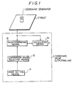
- Figure 1 is a block diagram of a co-ordinate reading apparatus according to the present invention. A co-ordinate designator 1 has a coil (not shown) for generating an alternating magnetic field. A
tablet 2 contains a plurality of conductors (not shown) called sense lines. A mode setting means 31 produces signals depending upon a mode that is selected. A comparison value selecting means 32 receives a signal from the mode setting means and produces a comparison value depending upon the mode set. The induction signal produced from thetablet 2 is compared with a comparison value produced from the comparison value selecting means 32 to determine whether the co-ordinate values are to be calculated or not. A calculatingmeans 34 which, when a signal produced from a height comparing means 33 indicates calculation of co-ordinates, receives the induction signal from thetablet 2 to calculate coordinate values. Output of the calculation means 34 is connected to an external unit (not shown) such as a computer that works as a general purpose inter-face, and the calculated co-ordinate value is produced. Themeans - The operation of the co-ordinate reading apparatus of Figure 1 will now be described. In the
tablet 2, the sense lines are selected successively. The operation of the selection of a predetermined number of sense lines is called "scanning". When the co-ordinate designator 1 is placed on atablet 2, the scanning is effected and induction signals are successively generated on the sense lines due to alternating current signals generated by the co-ordinate designator. The greatest induction signals are generated on the sense lines near the coordinate designator. A maximum value of the induction signals is called a "peak value". The peak value has height data relating to the height of the co-ordinate designator above thetablet 2. The peak value increases as the co-ordinate designator is brought close to the surface of the tablet and decreases as the co-ordinate designator is moved away from the surface of the tablet. In the mode setting means 31 is set either a relative co-ordinate mode or an absolute co-ordinate mode. A control signal from the mode setting means 31 is input to the comparison value selecting means 32 which selects a comparison value prepared for each of the modes for comparing the peak values. - The height comparing means 33 compares a peak value input from the
tablet 2 with a pre-set peak comparison value to determine whether the co-ordinate value is to be calculated or not. The peak comparison value is set to be high in the relative co-ordinate mode and is set to be low in the absolute co-ordinate mode. In the relative co-ordinate mode, therefore, the coordinate is not calculated unless the peak values are greater than those of the absolute co-ordinate mode, i.e. unless the co-ordinate designator is brought close to the tablet. The induction signal whose reading height is thus determined and produced, is then found as a co-ordinate value by the calculation means 34 and is sent to the external unit. In this case, the calculation means 34 finds a value of either the relative co-ordinate or of the absolute co-ordinate relying upon the data from the mode setting means 31. - The aforementioned co-ordinate
value outputting unit 3, in practice, is realised by a micro-processor and a program thereof. - Figure 2 is a block diagram of the co-ordinate
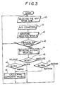
value outputting unit 3 of Figure 1. The induction signal detected by thetablet 2 is amplified to anamplifier 301, converted into a digital signal by an A/D converter 302, and is input to a micro-processor 303. The mode setting means 31 may be an electric switch whose output is read by the micro-processor 303. - The height of the co-ordinate designator from the induction signal or tablet is found, whether the coordinate value is to be determined or not. The processing for calculating the co-ordinate value has all been programmed into the micro-processor 303. Figure 3 is a flow chart of the program of the co-ordinate
value outputting unit 3. Sense lines are scanned insteps step 43, a peak value is detected instep 44 out of the induction signals that are input. The peak value is denoted by Vp. The mode setting means is tested in thestep 45 to determine whether it is the relative co-ordinate mode or the absolute co-ordinate mode. When the mode is the absolute co-ordinate mode,step 46 is executed and the peak value Vp is compared with a comparison value Vrel. When Vp ≧ Vrel in this step, a co-ordinate value is calculated from the induction signal instep 48 and is sent to the external unit. When Vp < Vrel, the co-ordinate value is not calculated, and the processing returns again to scanning i.e. steps 40, 41, 42, 43. When the absolute coordinate mode is detected instep 45,step 47 is executed. A comparison value Vabs instep 47 is different from that ofstep 46, i.e. Vrel > Vabs. - At which level the reading height is set, i.e. which values Vrel and Vabs are set, is determined in practice by evaluation experiment. According to the illustrated embodiment, the comparison value is so set that the reading height is about 10 mm in the absolute co-ordinate mode and is about 3 mm in the relative coordinate mode.
- As described above, the present invention provides a co-ordinate reading apparatus which selects either the relative co-ordinate mode or the absolute co-ordinate mode to calculate a co-ordinate value, the reading height being set relatively low in a relative coordinate mode and being set to relatively high in the absolute co-ordinate mode. In the relative co-ordinate mode, therefore, the co-ordinate designator does not need to be lifted up greatly during movement of the coordinate designator, contributing to improved operability. In the absolute co-ordinate mode, the reading height can be maintained as in the conventional co-ordinate reading apparatus.
- While the present invention has been described in relation to a co-ordinate reading apparatus of the electro-magnetic type it is also applicable to other types, e.g. the electro-static induction type, in which the co-ordinate designator and the tablet need not be brought into contact with each other to obtain the coordinate data.
Claims (5)
Applications Claiming Priority (2)
| Application Number | Priority Date | Filing Date | Title |
|---|---|---|---|
| JP20148787A JPS6444526A (en) | 1987-08-12 | 1987-08-12 | Coordinate reader |
| JP201487/87 | 1987-08-12 |
Publications (3)
| Publication Number | Publication Date |
|---|---|
| EP0303423A2 true EP0303423A2 (en) | 1989-02-15 |
| EP0303423A3 EP0303423A3 (en) | 1990-03-21 |
| EP0303423B1 EP0303423B1 (en) | 1993-10-20 |
Family
ID=16441874
Family Applications (1)
| Application Number | Title | Priority Date | Filing Date |
|---|---|---|---|
| EP88307297A Expired - Lifetime EP0303423B1 (en) | 1987-08-12 | 1988-08-08 | Co-ordinate reading apparatus |
Country Status (4)
| Country | Link |
|---|---|
| US (1) | US5025410A (en) |
| EP (1) | EP0303423B1 (en) |
| JP (1) | JPS6444526A (en) |
| DE (1) | DE3885033T2 (en) |
Cited By (1)
| Publication number | Priority date | Publication date | Assignee | Title |
|---|---|---|---|---|
| GB2247938A (en) * | 1990-08-18 | 1992-03-18 | David Roger Sherriff | Capacitative puck |
Families Citing this family (6)
| Publication number | Priority date | Publication date | Assignee | Title |
|---|---|---|---|---|
| JP3145385B2 (en) * | 1990-06-12 | 2001-03-12 | セイコーインスツルメンツ株式会社 | Wireless coordinate reader, coordinate indicator thereof, and switch state detecting method of the coordinate indicator |
| JPH08307954A (en) * | 1995-05-12 | 1996-11-22 | Sony Corp | Device and method for coordinate input and information processor |
| US6029214A (en) * | 1995-11-03 | 2000-02-22 | Apple Computer, Inc. | Input tablet system with user programmable absolute coordinate mode and relative coordinate mode segments |
| JPH10326146A (en) * | 1997-05-23 | 1998-12-08 | Wacom Co Ltd | Tool for coordinate input |
| JP5001928B2 (en) | 2008-10-20 | 2012-08-15 | サンデン株式会社 | Waste heat recovery system for internal combustion engines |
| US9727236B2 (en) * | 2014-08-28 | 2017-08-08 | Peigen Jiang | Computer input device |
Citations (5)
| Publication number | Priority date | Publication date | Assignee | Title |
|---|---|---|---|---|
| US3732557A (en) * | 1971-05-03 | 1973-05-08 | Evans & Sutherland Computer Co | Incremental position-indicating system |
| JPS57141785A (en) * | 1981-02-26 | 1982-09-02 | Fujitsu Ltd | Coordinate reader |
| JPS5955586A (en) * | 1982-09-24 | 1984-03-30 | Hitachi Seiko Ltd | Coordinate detector |
| EP0156593A2 (en) * | 1984-03-22 | 1985-10-02 | AMP INCORPORATED (a New Jersey corporation) | Method and apparatus for mode changes and/or touch mouse control |
| EP0242598A2 (en) * | 1986-04-25 | 1987-10-28 | International Business Machines Corporation | Minimun parallax stylus detection subsystem for a display device |
Family Cites Families (6)
| Publication number | Priority date | Publication date | Assignee | Title |
|---|---|---|---|---|
| DE3566932D1 (en) * | 1984-02-22 | 1989-01-26 | Wacom Co Ltd | Position detecting apparatus |
| DE3685839T2 (en) * | 1985-04-01 | 1993-05-13 | Hewlett Packard Co | DEVICE FOR DETECTING THE LOCATION OF AN OBJECT ON A TABLET. |
| EP0253993A3 (en) * | 1986-05-28 | 1990-02-14 | Hitachi, Ltd. | Position coordinate determining apparatus |
| JPS6326720A (en) * | 1986-07-18 | 1988-02-04 | Nippon Denki Shijiyou Kaihatsu Kk | Detecting device for frequency connecting position |
| DE3789922T2 (en) * | 1986-07-23 | 1995-01-05 | Wacom Co Ltd | Coordinate input system. |
| JPH0614310B2 (en) * | 1987-06-25 | 1994-02-23 | キヤノン株式会社 | Coordinate input device |
-
1987
- 1987-08-12 JP JP20148787A patent/JPS6444526A/en active Pending
-
1988
- 1988-08-08 EP EP88307297A patent/EP0303423B1/en not_active Expired - Lifetime
- 1988-08-08 DE DE88307297T patent/DE3885033T2/en not_active Expired - Fee Related
- 1988-08-11 US US07/233,263 patent/US5025410A/en not_active Expired - Lifetime
Patent Citations (5)
| Publication number | Priority date | Publication date | Assignee | Title |
|---|---|---|---|---|
| US3732557A (en) * | 1971-05-03 | 1973-05-08 | Evans & Sutherland Computer Co | Incremental position-indicating system |
| JPS57141785A (en) * | 1981-02-26 | 1982-09-02 | Fujitsu Ltd | Coordinate reader |
| JPS5955586A (en) * | 1982-09-24 | 1984-03-30 | Hitachi Seiko Ltd | Coordinate detector |
| EP0156593A2 (en) * | 1984-03-22 | 1985-10-02 | AMP INCORPORATED (a New Jersey corporation) | Method and apparatus for mode changes and/or touch mouse control |
| EP0242598A2 (en) * | 1986-04-25 | 1987-10-28 | International Business Machines Corporation | Minimun parallax stylus detection subsystem for a display device |
Non-Patent Citations (2)
| Title |
|---|
| PATENT ABSTRACTS OF JAPAN, vol. 6, no. 245 (P-159)[1123], 3rd December 1982; & JP-A-57 141 785 (FUJITSU K.K.) 02-09-1982 * |
| PATENT ABSTRACTS OF JAPAN, vol. 8, no. 159 (P-289), 24th July 1984; & JP-A-59 055 586 (HITACHI SEIKO) * |
Cited By (1)
| Publication number | Priority date | Publication date | Assignee | Title |
|---|---|---|---|---|
| GB2247938A (en) * | 1990-08-18 | 1992-03-18 | David Roger Sherriff | Capacitative puck |
Also Published As
| Publication number | Publication date |
|---|---|
| US5025410A (en) | 1991-06-18 |
| EP0303423A3 (en) | 1990-03-21 |
| EP0303423B1 (en) | 1993-10-20 |
| JPS6444526A (en) | 1989-02-16 |
| DE3885033T2 (en) | 1994-02-10 |
| DE3885033D1 (en) | 1993-11-25 |
Similar Documents
| Publication | Publication Date | Title |
|---|---|---|
| US5220324A (en) | Wireless coordinate reader and switch state detection system for coordinate indicator | |
| US5691513A (en) | Scanning method for sensor coils in coordinate data input device | |
| US5691512A (en) | Position transducer, and method for eliminating noise therefrom | |
| US6255604B1 (en) | Coordinate detecting device for outputting coordinate data when two points are simultaneously depressed, method therefor and computer control device | |
| US4794208A (en) | Frequency shifting digitizer for reducing AC fields interference | |
| US7423654B2 (en) | Image processing apparatus, display apparatus with touch panel, image processing method and computer program | |
| CA1154145A (en) | Magnification/demagnification apparatus and method | |
| US6239789B1 (en) | Position detecting method and apparatus for detecting a plurality of position indicators | |
| EP0646886B1 (en) | An apparatus for automatic fingerprint classification | |
| US6937226B2 (en) | Input device and pointer control method | |
| EP0694863B1 (en) | Position detecting method and device | |
| EP0303423B1 (en) | Co-ordinate reading apparatus | |
| EP0469274B1 (en) | Ultrasonic inspection and imaging instrument | |
| EP0565852A1 (en) | Optimal scan sequence for RF magnetic digitizers | |
| JPH0361208B2 (en) | ||
| US4939318A (en) | Digitizer pen tilt correction employing wires near the data point | |
| US5781181A (en) | Apparatus and method for changing an operation mode of a coordinate input apparatus | |
| US4473717A (en) | Digitizing system | |
| EP0427251A2 (en) | Method and device for graphics processing | |
| JPH1185380A (en) | Coordinate reader, its interface device, and coordinate reading system | |
| US5109225A (en) | Coordinate reader with pointer inclination compensation | |
| EP0511406A1 (en) | Device for reading out coordinate | |
| JPH09134246A (en) | Coordinate indicator or device used with coordinate reader | |
| JP2771788B2 (en) | Coordinate detecting device and angle information detecting method | |
| EP0051089B1 (en) | Method for the analysis of scanned data |
Legal Events
| Date | Code | Title | Description |
|---|---|---|---|
| PUAI | Public reference made under article 153(3) epc to a published international application that has entered the european phase |
Free format text: ORIGINAL CODE: 0009012 |
|
| AK | Designated contracting states |
Kind code of ref document: A2 Designated state(s): DE FR GB |
|
| PUAL | Search report despatched |
Free format text: ORIGINAL CODE: 0009013 |
|
| AK | Designated contracting states |
Kind code of ref document: A3 Designated state(s): DE FR GB |
|
| 17P | Request for examination filed |
Effective date: 19900604 |
|
| 17Q | First examination report despatched |
Effective date: 19920114 |
|
| GRAA | (expected) grant |
Free format text: ORIGINAL CODE: 0009210 |
|
| AK | Designated contracting states |
Kind code of ref document: B1 Designated state(s): DE FR GB |
|
| REF | Corresponds to: |
Ref document number: 3885033 Country of ref document: DE Date of ref document: 19931125 |
|
| ET | Fr: translation filed | ||
| REG | Reference to a national code |
Ref country code: GB Ref legal event code: 746 Effective date: 19940607 |
|
| PLBE | No opposition filed within time limit |
Free format text: ORIGINAL CODE: 0009261 |
|
| STAA | Information on the status of an ep patent application or granted ep patent |
Free format text: STATUS: NO OPPOSITION FILED WITHIN TIME LIMIT |
|
| 26N | No opposition filed | ||
| REG | Reference to a national code |
Ref country code: FR Ref legal event code: DL |
|
| REG | Reference to a national code |
Ref country code: GB Ref legal event code: IF02 |
|
| PGFP | Annual fee paid to national office [announced via postgrant information from national office to epo] |
Ref country code: GB Payment date: 20020807 Year of fee payment: 15 |
|
| PGFP | Annual fee paid to national office [announced via postgrant information from national office to epo] |
Ref country code: FR Payment date: 20020808 Year of fee payment: 15 |
|
| PGFP | Annual fee paid to national office [announced via postgrant information from national office to epo] |
Ref country code: DE Payment date: 20020816 Year of fee payment: 15 |
|
| PG25 | Lapsed in a contracting state [announced via postgrant information from national office to epo] |
Ref country code: GB Free format text: LAPSE BECAUSE OF NON-PAYMENT OF DUE FEES Effective date: 20030808 |
|
| PG25 | Lapsed in a contracting state [announced via postgrant information from national office to epo] |
Ref country code: DE Free format text: LAPSE BECAUSE OF NON-PAYMENT OF DUE FEES Effective date: 20040302 |
|
| GBPC | Gb: european patent ceased through non-payment of renewal fee |
Effective date: 20030808 |
|
| PG25 | Lapsed in a contracting state [announced via postgrant information from national office to epo] |
Ref country code: FR Free format text: LAPSE BECAUSE OF NON-PAYMENT OF DUE FEES Effective date: 20040430 |
|
| REG | Reference to a national code |
Ref country code: FR Ref legal event code: ST |